EP2645389B1 - Interlock switch circuit with single fault detection - Google Patents
Interlock switch circuit with single fault detection Download PDFInfo
- Publication number
- EP2645389B1 EP2645389B1 EP13161717.7A EP13161717A EP2645389B1 EP 2645389 B1 EP2645389 B1 EP 2645389B1 EP 13161717 A EP13161717 A EP 13161717A EP 2645389 B1 EP2645389 B1 EP 2645389B1
- Authority
- EP
- European Patent Office
- Prior art keywords
- switch
- safety
- diagnostic
- switches
- testing system
- Prior art date
- Legal status (The legal status is an assumption and is not a legal conclusion. Google has not performed a legal analysis and makes no representation as to the accuracy of the status listed.)
- Active
Links
Images
Classifications
-
- G—PHYSICS
- G01—MEASURING; TESTING
- G01R—MEASURING ELECTRIC VARIABLES; MEASURING MAGNETIC VARIABLES
- G01R31/00—Arrangements for testing electric properties; Arrangements for locating electric faults; Arrangements for electrical testing characterised by what is being tested not provided for elsewhere
- G01R31/327—Testing of circuit interrupters, switches or circuit-breakers
-
- H—ELECTRICITY
- H01—ELECTRIC ELEMENTS
- H01H—ELECTRIC SWITCHES; RELAYS; SELECTORS; EMERGENCY PROTECTIVE DEVICES
- H01H9/00—Details of switching devices, not covered by groups H01H1/00 - H01H7/00
- H01H9/20—Interlocking, locking, or latching mechanisms
- H01H9/22—Interlocking, locking, or latching mechanisms for interlocking between casing, cover, or protective shutter and mechanism for operating contacts
-
- H—ELECTRICITY
- H01—ELECTRIC ELEMENTS
- H01H—ELECTRIC SWITCHES; RELAYS; SELECTORS; EMERGENCY PROTECTIVE DEVICES
- H01H2300/00—Orthogonal indexing scheme relating to electric switches, relays, selectors or emergency protective devices covered by H01H
- H01H2300/052—Controlling, signalling or testing correct functioning of a switch
Definitions
- the present invention relates to a testing system to test safety interlock switches to ensure they are operating normally and in particular a system which enables easy testing of a plurality of such switches.
- An interlock switch is used to monitor the position of the guard. Power to the machinery is controlled through the interlock switch such that when the guard is opened the condition of the switch is altered and power is cut in order to enable safe access to the machine. When the guard is closed, the power supply is resumed.
- the problem is that if the switch fails, or is tampered with (overridden) by personnel desiring easier access to the machine, it is possible to open the guard without the machine powering down which gives rise to a safety hazard.
- Document US2002/0080006 discloses a device according to the preamble of claim 1 and a method according to the preamble of claim 10.
- test loop must be intact for the switches safety outputs to be closed.
- the safety loop is broken when an individual switch is activated to open its safety output.
- the diagnostic may include opening and closing the switch when the power is disabled.
- the diagnostic means may be adapted to ensure that the safety loop cannot be re-established if a fault is detected.
- the detected fault may be that at least one of the switches safety outputs remains closed.
- a diagnostic means is provided on each switch to perform a self check of that switch.
- the safety loop circuit may be broken when a fault is detected.
- the testing system may include indicating means to indicate the condition of the switch.
- the indicator means may include at least one of the conditions switch open ,switch closed, switch test diagnostic completed and switch operating normally and switch diagnostic completed and switch faulty.
- An indicator means may be provided on each switch to provide an indication of the condition of that switch.
- a plurality of safety switches 2 are provided.
- the switch 2 is a non-contact sensor style interlock in which the actuator 4 thereof is mounted to a guard (not shown) and the main switch body 6 to the frame of the guard.
- the switch body 6 When the guard is opened, the change of position of the actuator 4 is detected by the switch body 6 and the switch 2 changes its operating condition.
- This type of switch 2 is designed to be on when the guard is closed to prevent access to machinery; the on condition of the switch 2 enabling a power supply to the machine.
- the switch 2 is designed to switch off when the guard is opened, thereby disabling the power and by such the guarded machine powers down.
- Each switch 2 is connected to a power rail 8 and are also connected directly or indirectly to a monitoring controller 10 via an electronic safety output 12. When the operating condition of an individual switch 2 is altered, a signal is sent to the monitoring controller 10 through the safety output 12 which acts to enable or disable power to the machine, when the switch 2 is respectively closed and opened.
- Each switch 2 also has a safety input 14 which connects the switch 2 either directly or indirectly to the power rail 8.
- the switches 2 are connected in series by an internal test loop 16. Each switch 2 is also provided with an individual diagnostic capability in the form of a microprocessor 18.
- the test loop interconnects the devices and enables a signal to transmit around the devices to conduct a self test and prevent machine restart if a fault is detected.
- the internal test loop 16 is not connected to the power line 8 or to the monitoring controller 10.
- the test loop 16 is a continuous loop which needs to stay connected through all switches 2 it connects for the safety output 12 from each switch 2 to operate.
- test loop 16 if broken, a signal is sent which causes the safety output 12 to open on all switches 2, thereby stopping the machine. This creates an instant open/ closed check of all switches 2 whilst the machine is stopped. This is achieved by triggering each switch's microprocessor to perform a self diagnostic check.
- the safety output 12 from that switch 2 will open and also cause the loop 16 to break.
- the switch's on board microprocessor 18 monitors the switch condition and in turn sends a signal through the loop 16 which causes all other switch outputs 12 to open; the respective switch's output 12 being controlled by its own microprocessor 18.
- the open switch 2 is once again closed, its safety output 12 is closed and a signal is sent through the loop 16 to close the safety outputs of the other switches. Thereby power is once again enabled.
- Each switch 2 is provided with an indicator 20, 22 to show the operational status of each switch 2, in this example in the form of two coloured LED's.
- the green LED 20 indicates that the switch 2 is on and operating normally.
- the second LED 22 can change colour, when yellow is shown, it indicates that the individual switch is open and operating within normal parameters.
- the yellow also indicates that the self diagnostic has been performed and that the switch is operating normally.
- Yellow is also used in conjunction with green to indicate that an unopened switch has been checked and that it is working normally. In this instance, both LEDs are lit.
- the LED 22 can show two conditions and when it flashes red, whether or not it is opened, this indicates that this particular switch has developed a fault.
- the onboard microprocessor controls the indicator based on the detected condition of the switch when it performs its diagnostic.
- the microprocessor 18 acts to prevent the safety output 12 of the effected switch 2 from being re-established. Therefore the internal test loop 16 cannot be closed and the machine cannot be restarted.
- Fig 2 An example of this operation is given in Fig 2 .
- Fig. 2a all the switches 2 are closed, the machine is running.
- the green LED 20 on each switch is lit, the yellow LED 22 is switched off.
- Fig. 2b one of the switches 2c has been opened.
- the green LED 20 is not lit, the yellow LED 22 is lit to indicate that the switch has been checked and is in working order.
- the remaining unopened switches 2 have both LED lit, the green LED 20 to show that it is closed and the yellow LED 22 shown that the diagnostic has been performed and that it is in working order.
- the safety outputs 12 can be switched on, the test loop 16 can be once again completed and the machine restarted when the open switch 2c is closed.
- a fault has been found on an unopened switch 2b.
- the remaining switches have the condition and LED status as described with respect to condition described in Fig. 2b .
- the switch LED 22 shows a flashing red light to indicate that a fault has been found.
- the switches on-board microprocessor 18 will not allow that switch's safety output 12 to switch on, therefore the test loop 16 cannot be completed and the machine cannot be restarted.
- Each safety switch acts as a standalone device after the safety demand has taken place.
- the advantage of this is that an individual switch with a fault can be quickly replaced and the machine restarted. This eliminates the need for extensive rewiring, or even replacement of the complete safety circuit.
Landscapes
- Physics & Mathematics (AREA)
- General Physics & Mathematics (AREA)
- Testing Electric Properties And Detecting Electric Faults (AREA)
- Keying Circuit Devices (AREA)
- Emergency Protection Circuit Devices (AREA)
Description
- The present invention relates to a testing system to test safety interlock switches to ensure they are operating normally and in particular a system which enables easy testing of a plurality of such switches.
- Access to hazardous machinery is blocked by guards. An interlock switch is used to monitor the position of the guard. Power to the machinery is controlled through the interlock switch such that when the guard is opened the condition of the switch is altered and power is cut in order to enable safe access to the machine. When the guard is closed, the power supply is resumed. The problem is that if the switch fails, or is tampered with (overridden) by personnel desiring easier access to the machine, it is possible to open the guard without the machine powering down which gives rise to a safety hazard.
- To this end it is necessary to periodically test individual switches to ensure that when its respective guard is opened, power to the machinery is cut. It is possible to do this manually by opening the guard and observing that the machine powers down. However, many such guards and associated interlocks may be provided some of which may be in hard to reach positions. Individual testing of the switches is therefore time consuming, not only for the individual conducting the test whilst each door must be individually opened and closed; but this also results in considerable down time for the machinery guarded. In this respect, this type of testing may be infrequently conducted and certain guards, which are little used or are in hard to reach locations, may be missed during the test. This leads to a potential safety issue in that a failure may not be timely detected. Also the frequent stop/stan of the machine during testing may lead to damage thereof.
- Complex automated test systems have been developed to test the switches on mass. They are adapted such that if a single fault is detected, the machine is stopped. In a known system each switch is connected in series, such that each switch output provides the input to the next switch. Irrespective of whether a particular switch has been opened by a machine guard opening, a test signal is circulated through the switches in order to check that the input to output of every switch is operating. This is achieved by briefly opening and closing each switch. This has the disadvantage of causing a disruption to the power supply. The test signal is usually of a 30 second duration.
- Whilst this test may be more frequently conducted, this does not alleviate the problem of stopping and starting the machine in order to conduct the test. Also, the complex equipment may require several dedicated components for example a communication bus, microprocessor and hardwiring to power supply and controller. If a problem occurs, it may prove necessary to replace the entire testing system. Also, the system only tests interlock switches and not other associated safety devices for faults, such as emergency stop switches, closing of the interlock prior to test signal being applied. Therefore, a guard with a defective interlock may be opened prior to the test signal being applied and a corresponding safety issue arise.
- Document
US2002/0080006 discloses a device according to the preamble of claim 1 and a method according to the preamble ofclaim 10. - It is an object of the present invention to provide a safety circuit for a plurality of interlock switches which overcomes or alleviates the foregoing drawbacks.
- In accordance with the present invention there is provided a testing system according to claim 1.
- In a preferred embodiment the test loop must be intact for the switches safety outputs to be closed.
- The safety loop is broken when an individual switch is activated to open its safety output.
- The diagnostic may include opening and closing the switch when the power is disabled.
- The diagnostic means may be adapted to ensure that the safety loop cannot be re-established if a fault is detected.
- The detected fault may be that at least one of the switches safety outputs remains closed.
- A diagnostic means is provided on each switch to perform a self check of that switch.
- The safety loop circuit may be broken when a fault is detected.
- The testing system may include indicating means to indicate the condition of the switch. The indicator means may include at least one of the conditions switch open ,switch closed, switch test diagnostic completed and switch operating normally and switch diagnostic completed and switch faulty. An indicator means may be provided on each switch to provide an indication of the condition of that switch.
- By way of example only specific embodiments of the invention will now be described with reference to the accompanying drawings, in which:-
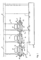
- Fig. 1
- is a schematic view of a testing circuit of the present invention used to provide a diagnostic capability to a plurality of series connected safety switches; and
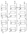
- Fig. 2a-2c
- are illustrations of fault detection sequences using the test circuit of
Fig. 1 . - In the example of
Fig. 1 , a plurality ofsafety switches 2 are provided. In this illustration, theswitch 2 is a non-contact sensor style interlock in which theactuator 4 thereof is mounted to a guard (not shown) and themain switch body 6 to the frame of the guard. When the guard is opened, the change of position of theactuator 4 is detected by theswitch body 6 and theswitch 2 changes its operating condition. This type ofswitch 2 is designed to be on when the guard is closed to prevent access to machinery; the on condition of theswitch 2 enabling a power supply to the machine. Theswitch 2 is designed to switch off when the guard is opened, thereby disabling the power and by such the guarded machine powers down. - Each
switch 2 is connected to apower rail 8 and are also connected directly or indirectly to amonitoring controller 10 via anelectronic safety output 12. When the operating condition of anindividual switch 2 is altered, a signal is sent to themonitoring controller 10 through thesafety output 12 which acts to enable or disable power to the machine, when theswitch 2 is respectively closed and opened. Eachswitch 2 also has asafety input 14 which connects theswitch 2 either directly or indirectly to thepower rail 8. - The
switches 2 are connected in series by aninternal test loop 16. Eachswitch 2 is also provided with an individual diagnostic capability in the form of amicroprocessor 18. The test loop interconnects the devices and enables a signal to transmit around the devices to conduct a self test and prevent machine restart if a fault is detected. - The
internal test loop 16 is not connected to thepower line 8 or to themonitoring controller 10. Thetest loop 16 is a continuous loop which needs to stay connected through allswitches 2 it connects for thesafety output 12 from eachswitch 2 to operate. - The
test loop 16 if broken, a signal is sent which causes thesafety output 12 to open on allswitches 2, thereby stopping the machine. This creates an instant open/ closed check of allswitches 2 whilst the machine is stopped. This is achieved by triggering each switch's microprocessor to perform a self diagnostic check. - If an
individual switch 2 is opened, then thesafety output 12 from thatswitch 2 will open and also cause theloop 16 to break. The switch's onboard microprocessor 18 monitors the switch condition and in turn sends a signal through theloop 16 which causes allother switch outputs 12 to open; the respective switch'soutput 12 being controlled by itsown microprocessor 18. When theopen switch 2 is once again closed, itssafety output 12 is closed and a signal is sent through theloop 16 to close the safety outputs of the other switches. Thereby power is once again enabled. - Each
switch 2 is provided with anindicator switch 2, in this example in the form of two coloured LED's. Thegreen LED 20 indicates that theswitch 2 is on and operating normally. Thesecond LED 22 can change colour, when yellow is shown, it indicates that the individual switch is open and operating within normal parameters. - The yellow also indicates that the self diagnostic has been performed and that the switch is operating normally.
- Yellow is also used in conjunction with green to indicate that an unopened switch has been checked and that it is working normally. In this instance, both LEDs are lit.
- As mentioned above, the
LED 22 can show two conditions and when it flashes red, whether or not it is opened, this indicates that this particular switch has developed a fault. - The onboard microprocessor controls the indicator based on the detected condition of the switch when it performs its diagnostic.
- Also, if a fault condition is detected during the diagnostic, the
microprocessor 18 acts to prevent thesafety output 12 of the effectedswitch 2 from being re-established. Therefore theinternal test loop 16 cannot be closed and the machine cannot be restarted. - An example of this operation is given in
Fig 2 . InFig. 2a , all theswitches 2 are closed, the machine is running. Thegreen LED 20 on each switch is lit, theyellow LED 22 is switched off. - In
Fig. 2b , one of the switches 2c has been opened. On the opened switch 2c, thegreen LED 20 is not lit, theyellow LED 22 is lit to indicate that the switch has been checked and is in working order. The remainingunopened switches 2 have both LED lit, thegreen LED 20 to show that it is closed and theyellow LED 22 shown that the diagnostic has been performed and that it is in working order. In this condition, there are no faults, thesafety outputs 12 can be switched on, thetest loop 16 can be once again completed and the machine restarted when the open switch 2c is closed. - In
Fig. 2c , a fault has been found on anunopened switch 2b. The remaining switches have the condition and LED status as described with respect to condition described inFig. 2b . However, on theswitch 2b on which a fault has been detected during its self diagnostic, theswitch LED 22 shows a flashing red light to indicate that a fault has been found. The switches on-board microprocessor 18 will not allow that switch'ssafety output 12 to switch on, therefore thetest loop 16 cannot be completed and the machine cannot be restarted. - This multiple turn off of every switch in series reduces the chance of a dangerous failure. In addition to the switch which has been opened, all switch
outputs 12 turn off. Theinternal test loop 16 is broken, not only by a normal opening of aswitch 2, but any breaks in theloop 16 at any safety demand. - This enables true safety demand testing which is achieved with no timed pulse-check. Each
safety switch 2 is checked when access to the machine is required. This reduces significantly the risk of, for example, an undetected short circuit due to the test time frequency of previous systems. - The true safety demand testing is achieved because of breakage of the
internal test loop 16 causing: - a) an immediate opening of the
safety output 12 on every switch in series irrespective of the number of switches; and - b) an immediate open/ close check of each switch output whilst the machine is stopped. This eliminates any need to periodically manually check the switches for correct operation. Also, the test is less inconvenient because the test is conducted when the machine is in any case in a powered down condition, rather than when in a powered condition. Thereby eliminating disruption to the machines normal working in order for safety checks to be conducted.
- Each safety switch acts as a standalone device after the safety demand has taken place. The advantage of this is that an individual switch with a fault can be quickly replaced and the machine restarted. This eliminates the need for extensive rewiring, or even replacement of the complete safety circuit.
- Whilst LED indicators have been described, other types of indicators could be provided.
- It is to be understood that although a simple switch incorporating sensor technology is used in this specific example, other types of interlock switches are intended to be covered such as non-contact sensor switch with coded sensor technology tongue operated interlock switched, interlocks with or without guard locks, together with other safety devices used to disable the power to the machine when access thereto is required, for example emergency stop buttons, pressure mats etc. Furthermore, a mixture of switches of different technologies may be connected by the test loop. The switch in question to be suitable for inclusion merely requiring a change of operating conditions when used to start and restart the machinery, which is detectable by a self diagnostic in order that a fault therein can be detected. This enables a plurality of safety devices to be tested individually when the machine is stopped by means of a self diagnostic.
Claims (13)
- A testing system to test a plurality of series connected safety switches (2) to ensure they are operating normally, each safety switch having a safety output (12) which when closed enables a power supply, characterized in that the testing system comprises an individual diagnostic means (18) on each switch (2) to perform a self check of that switch and which controls that switch's safety output (12), and a test loop circuit (16) which connects the diagnostic means (18) in series and which is adapted to send a signal to each diagnostic means (18) to open its switch's safety output (12) if any one safety switch (2) is activated to open its respective safety output (12), and wherein each diagnostic means (18) is also adapted to check its switch (2) to ensure that it is operating normally and which is activated when the test loop circuit (16) sends said signal.
- A testing system according to claim 1, wherein the test loop circuit (16) must be intact for the switches safety outputs (12) to be closed.
- A testing system according to claim 1 or 2, wherein the diagnostic includes opening and closing the switches (2) when the power supply is disabled.
- A testing system according to any one of the preceding claims, wherein the diagnostic means (18) is adapted to ensure that the power supply cannot be re-established if a fault is detected in at least one switch (2).
- A testing system according to claim 4, wherein the detected fault is that at least one of the switches safety outputs (12) remain closed.
- A testing system according to any one of the preceding claims, wherein the test loop circuit (16) cannot be re-established if a fault is detected by a diagnostic means (18).
- A testing system according to any one of the preceding claims, wherein the testing system includes indicating means (20, 22) to indicate the condition of the switch (2).
- A testing system according to claim 7, wherein the indicator means (20, 22) indicates at least one of the conditions switch open, switch closed, switch test diagnostic completed and switch operating normally, and switch diagnostic completed and switch faulty.
- A testing system according to anyone of the preceding claims, wherein an indicator means (20, 22) is provided on each switch (20) to provide an indication of the condition of that switch (2).
- A method of testing a plurality of series connected safety switches (2) to ensure they are operating normally, each safety switch (2) having a safety output (12) which when closed enables a power supply, characterized in that each safety switch (2) has an individual diagnostic means (18) which controls its safety output (12), and in a test loop circuit (16) which connects the individual diagnostic means (18) in a continuous loop, the method comprising the steps of changing the condition of an individual safety switch (2) by attempting to open its safety output (12), activating that individual switch's diagnostic means (18) by said change in condition, said individual switch's diagnostic means (18) then sending a signal round the test loop (16) to the other switches' individual diagnostic means (18) to instruct them to perform a self-check and each individual diagnostic means (18) then conducting a self check of its switch to ensure it is operating normally.
- A method according to claim 10, wherein if a fault in a safety switch is detected that switches diagnostic means (18) sends a signal round the test loop (16) to prevent power being enabled.
- A method according to claim 11, wherein the detected fault is that the switches safety output (12) remains closed.
- A method according to claim 10, 11 or 12, wherein each safety switch (2) has indicating means to show the condition of the switch (2) to indicate at least one of the conditions switch open, switch closed, switch test diagnostic completed and switch operating normally, and switch diagnostic completed and switch faulty.
Applications Claiming Priority (1)
| Application Number | Priority Date | Filing Date | Title |
|---|---|---|---|
| GBGB1205746.9A GB201205746D0 (en) | 2012-03-30 | 2012-03-30 | Interlock switch circuit with single fault detection |
Publications (3)
| Publication Number | Publication Date |
|---|---|
| EP2645389A2 EP2645389A2 (en) | 2013-10-02 |
| EP2645389A3 EP2645389A3 (en) | 2013-12-18 |
| EP2645389B1 true EP2645389B1 (en) | 2015-03-04 |
Family
ID=46160084
Family Applications (1)
| Application Number | Title | Priority Date | Filing Date |
|---|---|---|---|
| EP13161717.7A Active EP2645389B1 (en) | 2012-03-30 | 2013-03-28 | Interlock switch circuit with single fault detection |
Country Status (4)
| Country | Link |
|---|---|
| US (1) | US9188646B2 (en) |
| EP (1) | EP2645389B1 (en) |
| ES (1) | ES2538352T3 (en) |
| GB (1) | GB201205746D0 (en) |
Families Citing this family (3)
| Publication number | Priority date | Publication date | Assignee | Title |
|---|---|---|---|---|
| DE102015113110B4 (en) * | 2015-08-10 | 2019-03-14 | MAQUET GmbH | Drive device at least one drive device of a surgical table and method for driving |
| JP7336707B2 (en) * | 2020-01-24 | 2023-09-01 | パナソニックIpマネジメント株式会社 | Safety switches and switch systems |
| CN113608145B (en) * | 2021-07-14 | 2023-04-11 | 厦门科华数能科技有限公司 | Multi-path photovoltaic module ground fault detection device and detection method |
Citations (2)
| Publication number | Priority date | Publication date | Assignee | Title |
|---|---|---|---|---|
| US20020080006A1 (en) * | 2000-10-04 | 2002-06-27 | Honeywell International, Inc. | Thermal switch containing preflight test feature and fault location detection |
| US20090189612A1 (en) * | 2008-01-25 | 2009-07-30 | Mills Patrick W | Method of actuating a test function of an electrical switching apparatus at a panel and electrical switching apparatus employing the same |
Family Cites Families (7)
| Publication number | Priority date | Publication date | Assignee | Title |
|---|---|---|---|---|
| DE10001735B4 (en) * | 2000-01-17 | 2006-07-06 | Pilz Gmbh & Co. Kg | Protection against unwanted commissioning of a machine plant |
| DE10011211B4 (en) * | 2000-03-08 | 2004-08-05 | Pilz Gmbh & Co. | Safety relay and safety relay system |
| DE10020074C5 (en) * | 2000-04-22 | 2010-04-29 | Pilz Gmbh & Co. Kg | Modular safety relay system |
| DE102004020997A1 (en) * | 2004-04-19 | 2005-11-03 | Pilz Gmbh & Co. Kg | Safety switching device for a safety circuit |
| EP1703530B1 (en) * | 2005-03-16 | 2012-11-14 | Rockwell Automation Germany GmbH & Co. KG | Circuit arrangement and method for indicating the status of one of plurality of switches connected in series to a safety relay |
| EP2383623B1 (en) * | 2010-04-30 | 2012-12-05 | Rockwell Automation Germany GmbH & Co. KG | Modular safety switching device system with optical link |
| US8693159B2 (en) * | 2011-03-23 | 2014-04-08 | Rockwell Automation Technologies, Inc. | Method and apparatus for diagnostic coverage of safety components |
-
2012
- 2012-03-30 GB GBGB1205746.9A patent/GB201205746D0/en not_active Ceased
-
2013
- 2013-03-28 EP EP13161717.7A patent/EP2645389B1/en active Active
- 2013-03-28 US US13/853,003 patent/US9188646B2/en active Active
- 2013-03-28 ES ES13161717.7T patent/ES2538352T3/en active Active
Patent Citations (2)
| Publication number | Priority date | Publication date | Assignee | Title |
|---|---|---|---|---|
| US20020080006A1 (en) * | 2000-10-04 | 2002-06-27 | Honeywell International, Inc. | Thermal switch containing preflight test feature and fault location detection |
| US20090189612A1 (en) * | 2008-01-25 | 2009-07-30 | Mills Patrick W | Method of actuating a test function of an electrical switching apparatus at a panel and electrical switching apparatus employing the same |
Also Published As
| Publication number | Publication date |
|---|---|
| EP2645389A3 (en) | 2013-12-18 |
| US9188646B2 (en) | 2015-11-17 |
| ES2538352T3 (en) | 2015-06-19 |
| GB201205746D0 (en) | 2012-05-16 |
| EP2645389A2 (en) | 2013-10-02 |
| US20130285666A1 (en) | 2013-10-31 |
Similar Documents
| Publication | Publication Date | Title |
|---|---|---|
| US10366845B2 (en) | Monitored adaptable emergency off-switch | |
| JP5122465B2 (en) | Extraction supply system and method for supplying extraction to an aircraft | |
| AU2010310881B2 (en) | Remote isolation system, method and apparatus | |
| CN107976627A (en) | Method for diagnosing faults, system and the vehicle of motor driven systems | |
| EA010984B1 (en) | Emergency isolation valve controller with integral fault indicator | |
| CN107399303B (en) | Trade power station and protection system thereof | |
| WO2017056688A1 (en) | Monitoring system and vehicle control device | |
| CN106525417A (en) | Knob type shifter high and low-temperature durability test device with gear information monitoring function | |
| US9188646B2 (en) | Interlock switch circuit with single fault detection | |
| CN102720595A (en) | Engine overspeed protection and control method | |
| WO2012142674A2 (en) | Remote isolation system, method and apparatus | |
| CA2898671A1 (en) | Safety circuit-monitoring using alternating voltage | |
| CN103440850B (en) | A kind of redundancy display system | |
| JP2007516838A (en) | Apparatus and method for interrupting inductive loads in a fail-safe manner | |
| AU2014100216A4 (en) | Remote isolation system, method and apparatus | |
| US8693159B2 (en) | Method and apparatus for diagnostic coverage of safety components | |
| CN112141166B (en) | Motor train unit safety loop bypass system | |
| US6928855B2 (en) | Zero speed indicating devices and processes for testing same | |
| CN111378460A (en) | Coke oven coal tower gate control method | |
| CN100403614C (en) | Equipment limit intelligent control safety protecting system | |
| CN107304015B (en) | The power control of Emergency Elevator | |
| KR200358415Y1 (en) | An intelligent traffic control system | |
| CN206863059U (en) | High-potting intelligent and safe monitor device | |
| KR200298557Y1 (en) | System for Screening Oil Filter | |
| KR100275075B1 (en) | How to display sensor error in automated equipment |
Legal Events
| Date | Code | Title | Description |
|---|---|---|---|
| PUAI | Public reference made under article 153(3) epc to a published international application that has entered the european phase |
Free format text: ORIGINAL CODE: 0009012 |
|
| AK | Designated contracting states |
Kind code of ref document: A2 Designated state(s): AL AT BE BG CH CY CZ DE DK EE ES FI FR GB GR HR HU IE IS IT LI LT LU LV MC MK MT NL NO PL PT RO RS SE SI SK SM TR |
|
| AX | Request for extension of the european patent |
Extension state: BA ME |
|
| PUAL | Search report despatched |
Free format text: ORIGINAL CODE: 0009013 |
|
| AK | Designated contracting states |
Kind code of ref document: A3 Designated state(s): AL AT BE BG CH CY CZ DE DK EE ES FI FR GB GR HR HU IE IS IT LI LT LU LV MC MK MT NL NO PL PT RO RS SE SI SK SM TR |
|
| AX | Request for extension of the european patent |
Extension state: BA ME |
|
| RIC1 | Information provided on ipc code assigned before grant |
Ipc: H01H 9/22 20060101AFI20131114BHEP |
|
| 17P | Request for examination filed |
Effective date: 20140618 |
|
| RBV | Designated contracting states (corrected) |
Designated state(s): AL AT BE BG CH CY CZ DE DK EE ES FI FR GB GR HR HU IE IS IT LI LT LU LV MC MK MT NL NO PL PT RO RS SE SI SK SM TR |
|
| GRAP | Despatch of communication of intention to grant a patent |
Free format text: ORIGINAL CODE: EPIDOSNIGR1 |
|
| INTG | Intention to grant announced |
Effective date: 20140905 |
|
| GRAS | Grant fee paid |
Free format text: ORIGINAL CODE: EPIDOSNIGR3 |
|
| GRAA | (expected) grant |
Free format text: ORIGINAL CODE: 0009210 |
|
| AK | Designated contracting states |
Kind code of ref document: B1 Designated state(s): AL AT BE BG CH CY CZ DE DK EE ES FI FR GB GR HR HU IE IS IT LI LT LU LV MC MK MT NL NO PL PT RO RS SE SI SK SM TR |
|
| REG | Reference to a national code |
Ref country code: GB Ref legal event code: FG4D |
|
| REG | Reference to a national code |
Ref country code: CH Ref legal event code: EP |
|
| REG | Reference to a national code |
Ref country code: IE Ref legal event code: FG4D |
|
| REG | Reference to a national code |
Ref country code: AT Ref legal event code: REF Ref document number: 714485 Country of ref document: AT Kind code of ref document: T Effective date: 20150415 |
|
| REG | Reference to a national code |
Ref country code: DE Ref legal event code: R096 Ref document number: 602013001037 Country of ref document: DE Effective date: 20150416 |
|
| REG | Reference to a national code |
Ref country code: ES Ref legal event code: FG2A Ref document number: 2538352 Country of ref document: ES Kind code of ref document: T3 Effective date: 20150619 |
|
| REG | Reference to a national code |
Ref country code: AT Ref legal event code: MK05 Ref document number: 714485 Country of ref document: AT Kind code of ref document: T Effective date: 20150304 Ref country code: NL Ref legal event code: VDEP Effective date: 20150304 |
|
| PG25 | Lapsed in a contracting state [announced via postgrant information from national office to epo] |
Ref country code: SE Free format text: LAPSE BECAUSE OF FAILURE TO SUBMIT A TRANSLATION OF THE DESCRIPTION OR TO PAY THE FEE WITHIN THE PRESCRIBED TIME-LIMIT Effective date: 20150304 Ref country code: NO Free format text: LAPSE BECAUSE OF FAILURE TO SUBMIT A TRANSLATION OF THE DESCRIPTION OR TO PAY THE FEE WITHIN THE PRESCRIBED TIME-LIMIT Effective date: 20150604 Ref country code: HR Free format text: LAPSE BECAUSE OF FAILURE TO SUBMIT A TRANSLATION OF THE DESCRIPTION OR TO PAY THE FEE WITHIN THE PRESCRIBED TIME-LIMIT Effective date: 20150304 Ref country code: LT Free format text: LAPSE BECAUSE OF FAILURE TO SUBMIT A TRANSLATION OF THE DESCRIPTION OR TO PAY THE FEE WITHIN THE PRESCRIBED TIME-LIMIT Effective date: 20150304 Ref country code: FI Free format text: LAPSE BECAUSE OF FAILURE TO SUBMIT A TRANSLATION OF THE DESCRIPTION OR TO PAY THE FEE WITHIN THE PRESCRIBED TIME-LIMIT Effective date: 20150304 |
|
| REG | Reference to a national code |
Ref country code: LT Ref legal event code: MG4D |
|
| PG25 | Lapsed in a contracting state [announced via postgrant information from national office to epo] |
Ref country code: RS Free format text: LAPSE BECAUSE OF FAILURE TO SUBMIT A TRANSLATION OF THE DESCRIPTION OR TO PAY THE FEE WITHIN THE PRESCRIBED TIME-LIMIT Effective date: 20150304 Ref country code: LV Free format text: LAPSE BECAUSE OF FAILURE TO SUBMIT A TRANSLATION OF THE DESCRIPTION OR TO PAY THE FEE WITHIN THE PRESCRIBED TIME-LIMIT Effective date: 20150304 Ref country code: AT Free format text: LAPSE BECAUSE OF FAILURE TO SUBMIT A TRANSLATION OF THE DESCRIPTION OR TO PAY THE FEE WITHIN THE PRESCRIBED TIME-LIMIT Effective date: 20150304 Ref country code: GR Free format text: LAPSE BECAUSE OF FAILURE TO SUBMIT A TRANSLATION OF THE DESCRIPTION OR TO PAY THE FEE WITHIN THE PRESCRIBED TIME-LIMIT Effective date: 20150605 |
|
| PG25 | Lapsed in a contracting state [announced via postgrant information from national office to epo] |
Ref country code: NL Free format text: LAPSE BECAUSE OF FAILURE TO SUBMIT A TRANSLATION OF THE DESCRIPTION OR TO PAY THE FEE WITHIN THE PRESCRIBED TIME-LIMIT Effective date: 20150304 |
|
| PG25 | Lapsed in a contracting state [announced via postgrant information from national office to epo] |
Ref country code: SK Free format text: LAPSE BECAUSE OF FAILURE TO SUBMIT A TRANSLATION OF THE DESCRIPTION OR TO PAY THE FEE WITHIN THE PRESCRIBED TIME-LIMIT Effective date: 20150304 Ref country code: PT Free format text: LAPSE BECAUSE OF FAILURE TO SUBMIT A TRANSLATION OF THE DESCRIPTION OR TO PAY THE FEE WITHIN THE PRESCRIBED TIME-LIMIT Effective date: 20150706 Ref country code: CZ Free format text: LAPSE BECAUSE OF FAILURE TO SUBMIT A TRANSLATION OF THE DESCRIPTION OR TO PAY THE FEE WITHIN THE PRESCRIBED TIME-LIMIT Effective date: 20150304 Ref country code: EE Free format text: LAPSE BECAUSE OF FAILURE TO SUBMIT A TRANSLATION OF THE DESCRIPTION OR TO PAY THE FEE WITHIN THE PRESCRIBED TIME-LIMIT Effective date: 20150304 Ref country code: RO Free format text: LAPSE BECAUSE OF FAILURE TO SUBMIT A TRANSLATION OF THE DESCRIPTION OR TO PAY THE FEE WITHIN THE PRESCRIBED TIME-LIMIT Effective date: 20150304 |
|
| PG25 | Lapsed in a contracting state [announced via postgrant information from national office to epo] |
Ref country code: PL Free format text: LAPSE BECAUSE OF FAILURE TO SUBMIT A TRANSLATION OF THE DESCRIPTION OR TO PAY THE FEE WITHIN THE PRESCRIBED TIME-LIMIT Effective date: 20150304 Ref country code: IS Free format text: LAPSE BECAUSE OF FAILURE TO SUBMIT A TRANSLATION OF THE DESCRIPTION OR TO PAY THE FEE WITHIN THE PRESCRIBED TIME-LIMIT Effective date: 20150704 |
|
| REG | Reference to a national code |
Ref country code: DE Ref legal event code: R097 Ref document number: 602013001037 Country of ref document: DE |
|
| PLBE | No opposition filed within time limit |
Free format text: ORIGINAL CODE: 0009261 |
|
| STAA | Information on the status of an ep patent application or granted ep patent |
Free format text: STATUS: NO OPPOSITION FILED WITHIN TIME LIMIT |
|
| REG | Reference to a national code |
Ref country code: IE Ref legal event code: MM4A |
|
| PG25 | Lapsed in a contracting state [announced via postgrant information from national office to epo] |
Ref country code: IE Free format text: LAPSE BECAUSE OF NON-PAYMENT OF DUE FEES Effective date: 20150328 Ref country code: MC Free format text: LAPSE BECAUSE OF FAILURE TO SUBMIT A TRANSLATION OF THE DESCRIPTION OR TO PAY THE FEE WITHIN THE PRESCRIBED TIME-LIMIT Effective date: 20150304 Ref country code: DK Free format text: LAPSE BECAUSE OF FAILURE TO SUBMIT A TRANSLATION OF THE DESCRIPTION OR TO PAY THE FEE WITHIN THE PRESCRIBED TIME-LIMIT Effective date: 20150304 |
|
| 26N | No opposition filed |
Effective date: 20151207 |
|
| PG25 | Lapsed in a contracting state [announced via postgrant information from national office to epo] |
Ref country code: SI Free format text: LAPSE BECAUSE OF FAILURE TO SUBMIT A TRANSLATION OF THE DESCRIPTION OR TO PAY THE FEE WITHIN THE PRESCRIBED TIME-LIMIT Effective date: 20150304 |
|
| REG | Reference to a national code |
Ref country code: FR Ref legal event code: PLFP Year of fee payment: 4 |
|
| PG25 | Lapsed in a contracting state [announced via postgrant information from national office to epo] |
Ref country code: BE Free format text: LAPSE BECAUSE OF FAILURE TO SUBMIT A TRANSLATION OF THE DESCRIPTION OR TO PAY THE FEE WITHIN THE PRESCRIBED TIME-LIMIT Effective date: 20150304 |
|
| REG | Reference to a national code |
Ref country code: CH Ref legal event code: PL |
|
| PG25 | Lapsed in a contracting state [announced via postgrant information from national office to epo] |
Ref country code: MT Free format text: LAPSE BECAUSE OF FAILURE TO SUBMIT A TRANSLATION OF THE DESCRIPTION OR TO PAY THE FEE WITHIN THE PRESCRIBED TIME-LIMIT Effective date: 20150304 |
|
| PG25 | Lapsed in a contracting state [announced via postgrant information from national office to epo] |
Ref country code: CH Free format text: LAPSE BECAUSE OF NON-PAYMENT OF DUE FEES Effective date: 20160331 Ref country code: LI Free format text: LAPSE BECAUSE OF NON-PAYMENT OF DUE FEES Effective date: 20160331 |
|
| REG | Reference to a national code |
Ref country code: FR Ref legal event code: PLFP Year of fee payment: 5 |
|
| PG25 | Lapsed in a contracting state [announced via postgrant information from national office to epo] |
Ref country code: BG Free format text: LAPSE BECAUSE OF FAILURE TO SUBMIT A TRANSLATION OF THE DESCRIPTION OR TO PAY THE FEE WITHIN THE PRESCRIBED TIME-LIMIT Effective date: 20150304 Ref country code: HU Free format text: LAPSE BECAUSE OF FAILURE TO SUBMIT A TRANSLATION OF THE DESCRIPTION OR TO PAY THE FEE WITHIN THE PRESCRIBED TIME-LIMIT; INVALID AB INITIO Effective date: 20130328 |
|
| PG25 | Lapsed in a contracting state [announced via postgrant information from national office to epo] |
Ref country code: CY Free format text: LAPSE BECAUSE OF FAILURE TO SUBMIT A TRANSLATION OF THE DESCRIPTION OR TO PAY THE FEE WITHIN THE PRESCRIBED TIME-LIMIT Effective date: 20150304 |
|
| PG25 | Lapsed in a contracting state [announced via postgrant information from national office to epo] |
Ref country code: TR Free format text: LAPSE BECAUSE OF FAILURE TO SUBMIT A TRANSLATION OF THE DESCRIPTION OR TO PAY THE FEE WITHIN THE PRESCRIBED TIME-LIMIT Effective date: 20150304 |
|
| PG25 | Lapsed in a contracting state [announced via postgrant information from national office to epo] |
Ref country code: LU Free format text: LAPSE BECAUSE OF NON-PAYMENT OF DUE FEES Effective date: 20150328 |
|
| REG | Reference to a national code |
Ref country code: FR Ref legal event code: PLFP Year of fee payment: 6 |
|
| REG | Reference to a national code |
Ref country code: DE Ref legal event code: R082 Ref document number: 602013001037 Country of ref document: DE Representative=s name: WUNDERLICH & HEIM PATENTANWAELTE PARTNERSCHAFT, DE |
|
| PG25 | Lapsed in a contracting state [announced via postgrant information from national office to epo] |
Ref country code: SM Free format text: LAPSE BECAUSE OF FAILURE TO SUBMIT A TRANSLATION OF THE DESCRIPTION OR TO PAY THE FEE WITHIN THE PRESCRIBED TIME-LIMIT Effective date: 20150304 |
|
| PG25 | Lapsed in a contracting state [announced via postgrant information from national office to epo] |
Ref country code: MK Free format text: LAPSE BECAUSE OF FAILURE TO SUBMIT A TRANSLATION OF THE DESCRIPTION OR TO PAY THE FEE WITHIN THE PRESCRIBED TIME-LIMIT Effective date: 20150304 |
|
| PG25 | Lapsed in a contracting state [announced via postgrant information from national office to epo] |
Ref country code: AL Free format text: LAPSE BECAUSE OF FAILURE TO SUBMIT A TRANSLATION OF THE DESCRIPTION OR TO PAY THE FEE WITHIN THE PRESCRIBED TIME-LIMIT Effective date: 20150304 |
|
| P01 | Opt-out of the competence of the unified patent court (upc) registered |
Effective date: 20230524 |
|
| PGFP | Annual fee paid to national office [announced via postgrant information from national office to epo] |
Ref country code: ES Payment date: 20250430 Year of fee payment: 13 |
|
| PGFP | Annual fee paid to national office [announced via postgrant information from national office to epo] |
Ref country code: GB Payment date: 20260316 Year of fee payment: 14 |
|
| PGFP | Annual fee paid to national office [announced via postgrant information from national office to epo] |
Ref country code: DE Payment date: 20260327 Year of fee payment: 14 |
|
| PGFP | Annual fee paid to national office [announced via postgrant information from national office to epo] |
Ref country code: IT Payment date: 20260317 Year of fee payment: 14 |
|
| PGFP | Annual fee paid to national office [announced via postgrant information from national office to epo] |
Ref country code: FR Payment date: 20260316 Year of fee payment: 14 |