EP2644925A1 - Clutch disengagement control mechanism for mechanical automatic transmission - Google Patents
Clutch disengagement control mechanism for mechanical automatic transmission Download PDFInfo
- Publication number
- EP2644925A1 EP2644925A1 EP11843079.2A EP11843079A EP2644925A1 EP 2644925 A1 EP2644925 A1 EP 2644925A1 EP 11843079 A EP11843079 A EP 11843079A EP 2644925 A1 EP2644925 A1 EP 2644925A1
- Authority
- EP
- European Patent Office
- Prior art keywords
- speed
- brake
- clutch
- threshold
- measurement device
- Prior art date
- Legal status (The legal status is an assumption and is not a legal conclusion. Google has not performed a legal analysis and makes no representation as to the accuracy of the status listed.)
- Granted
Links
- 230000005540 biological transmission Effects 0.000 title claims abstract description 16
- 238000005259 measurement Methods 0.000 claims abstract description 47
- 238000001514 detection method Methods 0.000 claims description 4
- 238000000034 method Methods 0.000 description 11
- 230000000694 effects Effects 0.000 description 4
- 238000010586 diagram Methods 0.000 description 3
- 230000035939 shock Effects 0.000 description 3
- 238000012544 monitoring process Methods 0.000 description 2
- 230000003111 delayed effect Effects 0.000 description 1
- 230000004069 differentiation Effects 0.000 description 1
- 230000007935 neutral effect Effects 0.000 description 1
Images


Classifications
-
- B—PERFORMING OPERATIONS; TRANSPORTING
- B60—VEHICLES IN GENERAL
- B60W—CONJOINT CONTROL OF VEHICLE SUB-UNITS OF DIFFERENT TYPE OR DIFFERENT FUNCTION; CONTROL SYSTEMS SPECIALLY ADAPTED FOR HYBRID VEHICLES; ROAD VEHICLE DRIVE CONTROL SYSTEMS FOR PURPOSES NOT RELATED TO THE CONTROL OF A PARTICULAR SUB-UNIT
- B60W10/00—Conjoint control of vehicle sub-units of different type or different function
- B60W10/02—Conjoint control of vehicle sub-units of different type or different function including control of driveline clutches
-
- F—MECHANICAL ENGINEERING; LIGHTING; HEATING; WEAPONS; BLASTING
- F16—ENGINEERING ELEMENTS AND UNITS; GENERAL MEASURES FOR PRODUCING AND MAINTAINING EFFECTIVE FUNCTIONING OF MACHINES OR INSTALLATIONS; THERMAL INSULATION IN GENERAL
- F16D—COUPLINGS FOR TRANSMITTING ROTATION; CLUTCHES; BRAKES
- F16D48/00—External control of clutches
- F16D48/06—Control by electric or electronic means, e.g. of fluid pressure
-
- B—PERFORMING OPERATIONS; TRANSPORTING
- B60—VEHICLES IN GENERAL
- B60T—VEHICLE BRAKE CONTROL SYSTEMS OR PARTS THEREOF; BRAKE CONTROL SYSTEMS OR PARTS THEREOF, IN GENERAL; ARRANGEMENT OF BRAKING ELEMENTS ON VEHICLES IN GENERAL; PORTABLE DEVICES FOR PREVENTING UNWANTED MOVEMENT OF VEHICLES; VEHICLE MODIFICATIONS TO FACILITATE COOLING OF BRAKES
- B60T8/00—Arrangements for adjusting wheel-braking force to meet varying vehicular or ground-surface conditions, e.g. limiting or varying distribution of braking force
- B60T8/32—Arrangements for adjusting wheel-braking force to meet varying vehicular or ground-surface conditions, e.g. limiting or varying distribution of braking force responsive to a speed condition, e.g. acceleration or deceleration
- B60T8/321—Arrangements for adjusting wheel-braking force to meet varying vehicular or ground-surface conditions, e.g. limiting or varying distribution of braking force responsive to a speed condition, e.g. acceleration or deceleration deceleration
- B60T8/3215—Systems characterised by having means acting on components of the drive line, e.g. retarder, clutch or differential gear
-
- B—PERFORMING OPERATIONS; TRANSPORTING
- B60—VEHICLES IN GENERAL
- B60W—CONJOINT CONTROL OF VEHICLE SUB-UNITS OF DIFFERENT TYPE OR DIFFERENT FUNCTION; CONTROL SYSTEMS SPECIALLY ADAPTED FOR HYBRID VEHICLES; ROAD VEHICLE DRIVE CONTROL SYSTEMS FOR PURPOSES NOT RELATED TO THE CONTROL OF A PARTICULAR SUB-UNIT
- B60W10/00—Conjoint control of vehicle sub-units of different type or different function
- B60W10/18—Conjoint control of vehicle sub-units of different type or different function including control of braking systems
- B60W10/184—Conjoint control of vehicle sub-units of different type or different function including control of braking systems with wheel brakes
-
- B—PERFORMING OPERATIONS; TRANSPORTING
- B60—VEHICLES IN GENERAL
- B60T—VEHICLE BRAKE CONTROL SYSTEMS OR PARTS THEREOF; BRAKE CONTROL SYSTEMS OR PARTS THEREOF, IN GENERAL; ARRANGEMENT OF BRAKING ELEMENTS ON VEHICLES IN GENERAL; PORTABLE DEVICES FOR PREVENTING UNWANTED MOVEMENT OF VEHICLES; VEHICLE MODIFICATIONS TO FACILITATE COOLING OF BRAKES
- B60T2201/00—Particular use of vehicle brake systems; Special systems using also the brakes; Special software modules within the brake system controller
- B60T2201/03—Brake assistants
-
- B—PERFORMING OPERATIONS; TRANSPORTING
- B60—VEHICLES IN GENERAL
- B60T—VEHICLE BRAKE CONTROL SYSTEMS OR PARTS THEREOF; BRAKE CONTROL SYSTEMS OR PARTS THEREOF, IN GENERAL; ARRANGEMENT OF BRAKING ELEMENTS ON VEHICLES IN GENERAL; PORTABLE DEVICES FOR PREVENTING UNWANTED MOVEMENT OF VEHICLES; VEHICLE MODIFICATIONS TO FACILITATE COOLING OF BRAKES
- B60T2260/00—Interaction of vehicle brake system with other systems
- B60T2260/04—Automatic transmission
-
- F—MECHANICAL ENGINEERING; LIGHTING; HEATING; WEAPONS; BLASTING
- F16—ENGINEERING ELEMENTS AND UNITS; GENERAL MEASURES FOR PRODUCING AND MAINTAINING EFFECTIVE FUNCTIONING OF MACHINES OR INSTALLATIONS; THERMAL INSULATION IN GENERAL
- F16D—COUPLINGS FOR TRANSMITTING ROTATION; CLUTCHES; BRAKES
- F16D2500/00—External control of clutches by electric or electronic means
- F16D2500/30—Signal inputs
- F16D2500/31—Signal inputs from the vehicle
- F16D2500/3108—Vehicle speed
-
- F—MECHANICAL ENGINEERING; LIGHTING; HEATING; WEAPONS; BLASTING
- F16—ENGINEERING ELEMENTS AND UNITS; GENERAL MEASURES FOR PRODUCING AND MAINTAINING EFFECTIVE FUNCTIONING OF MACHINES OR INSTALLATIONS; THERMAL INSULATION IN GENERAL
- F16D—COUPLINGS FOR TRANSMITTING ROTATION; CLUTCHES; BRAKES
- F16D2500/00—External control of clutches by electric or electronic means
- F16D2500/30—Signal inputs
- F16D2500/314—Signal inputs from the user
- F16D2500/31406—Signal inputs from the user input from pedals
- F16D2500/31426—Brake pedal position
-
- F—MECHANICAL ENGINEERING; LIGHTING; HEATING; WEAPONS; BLASTING
- F16—ENGINEERING ELEMENTS AND UNITS; GENERAL MEASURES FOR PRODUCING AND MAINTAINING EFFECTIVE FUNCTIONING OF MACHINES OR INSTALLATIONS; THERMAL INSULATION IN GENERAL
- F16D—COUPLINGS FOR TRANSMITTING ROTATION; CLUTCHES; BRAKES
- F16D2500/00—External control of clutches by electric or electronic means
- F16D2500/50—Problem to be solved by the control system
- F16D2500/508—Relating driving conditions
- F16D2500/50816—Control during a braking operation, e.g. during ABS control
-
- F—MECHANICAL ENGINEERING; LIGHTING; HEATING; WEAPONS; BLASTING
- F16—ENGINEERING ELEMENTS AND UNITS; GENERAL MEASURES FOR PRODUCING AND MAINTAINING EFFECTIVE FUNCTIONING OF MACHINES OR INSTALLATIONS; THERMAL INSULATION IN GENERAL
- F16D—COUPLINGS FOR TRANSMITTING ROTATION; CLUTCHES; BRAKES
- F16D2500/00—External control of clutches by electric or electronic means
- F16D2500/70—Details about the implementation of the control system
- F16D2500/704—Output parameters from the control unit; Target parameters to be controlled
- F16D2500/70422—Clutch parameters
- F16D2500/70424—Outputting a clutch engaged-disengaged signal
Definitions
- the present invention relates to mechanical automatic transmissions, more particularly, to control of disengaging clutch used in a mechanical automatic transmission, that is, clutch disengagement control technique.
- Patent Literature 1 As another prior art, a clutch control device that automatically "disengages" a clutch in response to brake operation is disclosed (refer to Patent Literature 1).
- Patent Literature 1 is configured such that, in a case where the vehicle speed is less than or equal to a predetermined vehicle speed and the engine speed is less than or equal to a predetermined engine speed while a vehicle is running, when it is recognized that a brake is operated, a clutch actuator is operated to disengage the clutch and, when the vehicle is stopped, a transmission gear is shifted to neutral position and the "disengagement" operation of the clutch actuator is stopped to engage the clutch, and does not solve the above-described problem.
- Patent Literature 1 Japanese Patent Application Non-examined Publication Gazette No. H9-42443 ( JPA H9-42443 )
- the present invention has been proposed in view of the above-described problem of the prior arts, and an object thereof is to provide a clutch disengagement control mechanism for a mechanical automatic transmission, said clutch disengagement control mechanism being performed clutch disengagement control operation with an optimal timing during both ordinary driving and low-speed driving just before a vehicle is stopped.
- a clutch disengagement mechanism for a mechanical automatic transmission of the present invention is characterized in that the clutch disengagement mechanism includes: a vehicle speed measurement device (an engine rotation sensor 3 and a gear position sensor 6 or a vehicle speed sensor 4) that measures a vehicle speed (X); a brake-operation-speed measurement device that measures a brake operation speed; a clutch operation device (9) that performs a clutch disengagement operation; and a control device (10), the control device (10) has the function of, when the vehicle speed (X) is more than or equal to a first threshold (A), issuing, to the clutch operation device (9), a control signal that disengages a clutch when the brake operation speed is more than or equal to a second threshold (B: for example, the rate of deceleration 30%/sec) and has the function of, when the vehicle speed (X) is less than the first threshold (A), issuing, to the clutch operation device (9), a control signal that disengages the clutch when the brake operation speed is more than or equal to a third threshold (C: for example, the rate of de
- the vehicle speed measurement device includes an engine-speed measurement device (3) that detects an engine speed of the vehicle, a gear position measurement device (6) that detects a gear position in a transmission, and the control device (10) and the control device (10) has the function of determining the vehicle speed based on the gear position in the transmission, the gear position detected by the gear position measurement device (6), and the engine speed of the vehicle, the engine speed detected by the engine-speed measurement device (3).
- the brake-operation-speed measurement device includes a brake signal measurement device (7) that detects the presence or absence of a brake signal, the control device (10), and a timer device (a timer 12) provided therein and the control device (10) has the function of determining the brake operation speed (that is, the rate of decrease in vehicle speed) based on the vehicle speed determined by the control device (10) and the length of time (measured by the timer 12) that has elapsed since the detection of the brake signal by the brake signal measurement device.
- the vehicle speed measurement device is formed of a vehicle speed sensor (4)
- the brake-operation-speed measurement device includes a brake signal measurement device (7) that detects the presence or absence of a brake signal, the control device (10), and a timer device (a timer 12) provided therein, and the control device (10) has the function of determining the brake operation speed (that is, the rate of decrease in vehicle speed) based on the vehicle speed measured by the vehicle speed sensor (4) and the length of time (measured by the timer 12) that has elapsed since the detection of the brake signal by the brake signal measurement device (7).
- the values of the first to third thresholds (A, B, and C) can be set at any values.
- the threshold based on which a control signal that disengages a clutch is issued to the clutch operation device (9) two types of thresholds: the threshold (the second threshold B) in high-speed driving and the threshold (the third threshold C) in low-speed driving are set, and these thresholds (the second threshold B and the third threshold C) are configured so as to be switched based on the vehicle speed.
- the third threshold (C: for example, the rate of deceleration 10%/sec) set at a slow value is used.
- the clutch is disengaged reliably, which prevents a so-called “feeling that the vehicle is pushed out” from being produced and prevents a shock caused when the vehicle is stopped in a state in which the clutch is engaged.
- the second threshold (B: for example, the rate of deceleration 30%/sec), for example, is used, and, by setting the second threshold (B) relatively high, the clutch is prevented from being brought into a "disengagement" state as a result of a determination that the brake operation speed is too high being made. As a result, the vehicle is reliably prevented from running at idle.
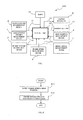
- Fig. 1 illustrates the configuration of a control system of a clutch disengagement mechanism for a mechanical automatic transmission (hereinafter referred to as a "clutch disengagement mechanism") whose whole portion is identified with reference character 100.
- the clutch disengagement mechanism 100 includes a control unit 10, an accelerator opening measurement device (hereinafter referred to as an “accelerator opening sensor”) 1, an engine-torque measurement device (hereinafter referred to as an “engine-torque sensor”) 2, an engine-speed measurement device (hereinafter referred to as an “engine rotation sensor”) 3, a clutch stroke measurement device (hereinafter referred to as a “clutch stroke sensor”) 5, a gear position measurement device (hereinafter referred to as a "gear position sensor”) 6, a brake signal measurement device (hereinafter referred to as a “brake sensor”) 7, a clutch actuator 9, a display section 11, and a timer 12.
- a control unit 10 an accelerator opening measurement device (hereinafter referred to as an “accelerator opening sensor”) 1
- an engine-torque measurement device hereinafter referred to as an “engine-torque sensor”
- engine rotation sensor an engine-speed measurement device
- a clutch stroke measurement device hereinafter referred to as a "clut
- the control unit 10 is connected to the accelerator opening sensor 1, the engine-torque sensor 2, the engine rotation sensor 3, the clutch stroke sensor 5, the gear position sensor 6, the brake sensor 7, and the timer 12 by input signal lines Li. Moreover, the control unit 10 is connected to the clutch actuator 9 and the display section 11 by control signal lines Lo.
- the control unit 10 has the function of, when a vehicle speed (X) is more than or equal to a first threshold (A), issuing, to the clutch actuator 9, a control signal that disengages a clutch when a brake operation speed is more than or equal to a second threshold (B: for example, the rate of deceleration 30%/sec). Moreover, the control unit 10 has the function of, when the vehicle speed (X) is less than the first threshold (A), issuing, to the clutch actuator 9, a control signal that disengages the clutch when the brake operation speed is more than or equal to a third threshold (C: for example, the rate of deceleration 10%/sec).
- the second threshold (B) of the brake operation speed is a value more than the third threshold (C) (the rate of deceleration 30%/sec > the rate of deceleration 10%/sec).
- step S1 of Fig. 2 the control unit 10 obtains the vehicle speed by performing a computation.
- the computation for obtaining the vehicle speed is performed by a flowchart of Fig. 3 , which will be described later.
- step S2 the control unit 10 determines whether or not the vehicle speed X is more than or equal to the predetermined value A by comparing the vehicle speed X obtained by performing a computation with the predetermined value (the predetermined vehicle speed: the first threshold) A stored in an unillustrated database in the control unit 10. If the vehicle speed X is more than or equal to the predetermined value A (step S1 is YES), the procedure proceeds to step S3; if the vehicle speed X is less than the predetermined value A (step S1 is NO), the procedure proceeds to step S5.
- step S3 the control unit 10 determines whether or not the brake operation speed is more than or equal to the predetermined value B. If the brake operation speed is more than or equal to the predetermined value (the second threshold) B (step S3 is YES), the control unit 10 disengages the clutch by issuing a control signal to the clutch actuator 9 (clutch disengagement: step S4). On the other hand, if the brake operation speed is less than the predetermined value (the second threshold) B (step S3 is NO), the control unit 10 ends the control.
- step S5 the control unit 10 determines whether or not the brake operation speed is more than or equal to the predetermined value (the third threshold) C.
- the third threshold (C) of the brake operation speed is a value less than the second threshold (B) (the rate of deceleration 30%/sec > the rate of deceleration 10%/sec). If the brake operation speed is more than or equal to the predetermined value (the third threshold) C (step S5 is YES), the control unit 10 disengages the clutch by issuing a control signal to the clutch actuator 9 (clutch disengagement: step S6). On the other hand, if the brake operation speed is less than the predetermined value (the third threshold) C (step S3 is NO), the control unit 10 ends the control.
- the brake operation speed in step S3 and step S5 is obtained by performing a computation by a flowchart of Fig. 4 , which will be described later.
- step S11 of Fig. 3 the control unit 10 detects the engine speed and the gear position based on the information from the engine rotation sensor 3 and the gear position sensor 6. Then, the control unit 10 obtains the vehicle speed by performing a computation based on the engine speed and the gear position (step S12).
- step S21 of Fig. 4 the control unit 10 obtains the vehicle speed by performing a computation by the method described by referring to the control flowchart of Fig. 3 .
- step S22 the control unit 10 waits until a brake signal is detected while monitoring a signal from the brake sensor 7 (a loop created when step S22 is NO), and, when the brake signal is detected (step S22 is YES), the control unit 10 immediately operates the timer (step S23).
- step S24 though not illustrated in Fig.
- the control unit 10 obtains the amount of change of the vehicle speed by performing a computation based on the vehicle speed obtained when a predetermined time has elapsed from the time when the timer was operated and the vehicle speed obtained in step S21.
- the control unit 10 obtains the deceleration of the vehicle, that is, the brake operation speed by performing a computation by dividing the amount of change of the vehicle speed obtained in step S24 by the elapsed time (by differentiation).
- the threshold of the brake operation speed based on which a control signal for clutch disengagement is issued to the clutch actuator 9 two types of thresholds: the threshold (the second threshold B) in high-speed driving and the threshold (the third threshold C) in low-speed driving are set. Moreover, these thresholds (the second threshold B and the third threshold C) are configured so as to be switched based on the vehicle speed. In addition, during low-speed driving such as driving in a traffic congestion, as the threshold of the brake operation speed based on which a control signal that disengages a clutch is issued to a clutch operation device, the third threshold (C: for example, the rate of deceleration 10%/sec) set at a slow value is used.
- the clutch is disengaged reliably, which prevents a so-called “feeling that the vehicle is pushed out” from being produced and prevents a shock caused when the vehicle is stopped in a state in which the clutch is engaged.
- the second threshold (B: for example, the rate of deceleration 30%/sec), for example, is used, and, by setting the second threshold (B) relatively high, the clutch is prevented from being brought into a "disengagement" state as a result of a determination that the brake operation speed is too high being made. As a result, the vehicle is reliably prevented from running at idle.
- the second embodiment of Fig. 5 (the whole of a clutch disengagement mechanism is identified with reference character 100A) is an embodiment obtained by adding a vehicle speed measurement device (hereinafter referred to as a "vehicle speed sensor") 4 to the first embodiment having the configuration of Fig. 1 .
- vehicle speed sensor vehicle speed measurement device
- the second embodiment of Fig. 5 can directly obtain the vehicle speed by the vehicle speed sensor 4. Therefore, in the second embodiment of Fig. 5 , control for a computation of the vehicle speed as illustrated in Fig. 3 is not needed.
- the second embodiment of Fig. 5 is substantially the same as the first embodiment and the operations and effects of the second embodiment are also the same as those of the first embodiment.
- the third embodiment of Figs. 6 and 7 (the whole of a clutch disengagement mechanism is identified with reference character 100B) is obtained by adding a brake stroke measurement device (hereinafter referred to as a "brake stroke sensor") 8 to the first embodiment of Figs. 1 to 4 .
- a brake stroke measurement device hereinafter referred to as a "brake stroke sensor”
- a method for obtaining the brake speed by performing a computation in the third embodiment differs from the method for obtaining the brake speed by performing a computation in the first embodiment.
- step S31 of Fig. 7 the control unit 10 waits until a brake signal is detected while monitoring a signal from the brake sensor 7 (a loop created when step S31 is NO), and, when the brake signal is detected (step S31 is YES), the control unit 10 immediately operates the timer 12 (step S32).
- step S33 the control unit 10 measures the brake stroke by the brake stroke sensor 8, proceeds to step S34, and obtains the brake operation speed by performing a computation by dividing the brake stroke obtained in step S33 by the elapsed time required for the pedal to be fully stepped on (the time that elapses before the step-on amount reaches the maximum amount after the pedal begins to be stepped on: this time can be known by a known technique).
- a brake-operation-speed measurement device is formed of the brake stroke sensor 8, the timer 12, and the control unit 10. Except for the above difference in the configuration, the third embodiment of Figs. 6 and 7 is substantially the same as the first embodiment and the operations and effects of the third embodiment are also the same as those of the first embodiment. Moreover, it is also possible to combine the second embodiment and the third embodiment. The operations and effects in that case is also the same as those of the first embodiment.
Landscapes
- Engineering & Computer Science (AREA)
- Mechanical Engineering (AREA)
- Transportation (AREA)
- General Engineering & Computer Science (AREA)
- Chemical & Material Sciences (AREA)
- Combustion & Propulsion (AREA)
- Physics & Mathematics (AREA)
- Fluid Mechanics (AREA)
- Hydraulic Clutches, Magnetic Clutches, Fluid Clutches, And Fluid Joints (AREA)
Abstract
Description
- The present invention relates to mechanical automatic transmissions, more particularly, to control of disengaging clutch used in a mechanical automatic transmission, that is, clutch disengagement control technique.
- It is well known control mechanism that disengages a clutch by determining that "panic braking" is performed if the operation speed of a brake pedal exceeds a predetermined value when a vehicle is running. A problem of such control is that, when the predetermined value is set low, the clutch is disengaged frequently while the vehicle is running and the vehicle runs at idle for a moment.
To overcome such a problem, the predetermined value may be set high. However, setting the predetermined value high tends to slow the speed at which the brake is stepped on when the vehicle speed is slow as in a traffic congestion, which creates a situation in which the clutch cannot be disengaged even when the brake is stepped on to disengage the clutch.
Specifically, even when the brake pedal is stepped on when the vehicle is running at low speed just before the vehicle is stopped, clutch disengagement timing is delayed, and a feeling that the vehicle is pushed out, a shock to the human body, and the like make a driver uneasy. - As another prior art, a clutch control device that automatically "disengages" a clutch in response to brake operation is disclosed (refer to Patent Literature 1).
However,Patent Literature 1 is configured such that, in a case where the vehicle speed is less than or equal to a predetermined vehicle speed and the engine speed is less than or equal to a predetermined engine speed while a vehicle is running, when it is recognized that a brake is operated, a clutch actuator is operated to disengage the clutch and, when the vehicle is stopped, a transmission gear is shifted to neutral position and the "disengagement" operation of the clutch actuator is stopped to engage the clutch, and does not solve the above-described problem. - Patent Literature 1: Japanese Patent Application Non-examined Publication Gazette No.
H9-42443 JPA H9-42443 - The present invention has been proposed in view of the above-described problem of the prior arts, and an object thereof is to provide a clutch disengagement control mechanism for a mechanical automatic transmission, said clutch disengagement control mechanism being performed clutch disengagement control operation with an optimal timing during both ordinary driving and low-speed driving just before a vehicle is stopped.
- A clutch disengagement mechanism for a mechanical automatic transmission of the present invention is characterized in that the clutch disengagement mechanism includes: a vehicle speed measurement device (an
engine rotation sensor 3 and agear position sensor 6 or a vehicle speed sensor 4) that measures a vehicle speed (X); a brake-operation-speed measurement device that measures a brake operation speed; a clutch operation device (9) that performs a clutch disengagement operation; and a control device (10), the control device (10) has the function of, when the vehicle speed (X) is more than or equal to a first threshold (A), issuing, to the clutch operation device (9), a control signal that disengages a clutch when the brake operation speed is more than or equal to a second threshold (B: for example, the rate of deceleration 30%/sec) and has the function of, when the vehicle speed (X) is less than the first threshold (A), issuing, to the clutch operation device (9), a control signal that disengages the clutch when the brake operation speed is more than or equal to a third threshold (C: for example, the rate ofdeceleration 10%/sec), and the second threshold (B) of the brake operation speed is a value more than the third threshold (C) (the rate of deceleration 30%/sec > the rate ofdeceleration 10%/sec). - In the present invention, it is preferable that the vehicle speed measurement device includes an engine-speed measurement device (3) that detects an engine speed of the vehicle, a gear position measurement device (6) that detects a gear position in a transmission, and the control device (10) and the control device (10) has the function of determining the vehicle speed based on the gear position in the transmission, the gear position detected by the gear position measurement device (6), and the engine speed of the vehicle, the engine speed detected by the engine-speed measurement device (3).
- In that case, it is preferable that the brake-operation-speed measurement device includes a brake signal measurement device (7) that detects the presence or absence of a brake signal, the control device (10), and a timer device (a timer 12) provided therein and the control device (10) has the function of determining the brake operation speed (that is, the rate of decrease in vehicle speed) based on the vehicle speed determined by the control device (10) and the length of time (measured by the timer 12) that has elapsed since the detection of the brake signal by the brake signal measurement device.
- Alternatively, it is preferable that the vehicle speed measurement device is formed of a vehicle speed sensor (4), the brake-operation-speed measurement device includes a brake signal measurement device (7) that detects the presence or absence of a brake signal, the control device (10), and a timer device (a timer 12) provided therein, and the control device (10) has the function of determining the brake operation speed (that is, the rate of decrease in vehicle speed) based on the vehicle speed measured by the vehicle speed sensor (4) and the length of time (measured by the timer 12) that has elapsed since the detection of the brake signal by the brake signal measurement device (7).
- Incidentally, in the present invention, it is preferable that the values of the first to third thresholds (A, B, and C) can be set at any values.
- According to the present invention provided with the above-described configuration, as the threshold based on which a control signal that disengages a clutch is issued to the clutch operation device (9), two types of thresholds: the threshold (the second threshold B) in high-speed driving and the threshold (the third threshold C) in low-speed driving are set, and these thresholds (the second threshold B and the third threshold C) are configured so as to be switched based on the vehicle speed.
In addition, during low-speed driving such as driving in a traffic congestion, as the threshold of the brake operation speed based on which a control signal that disengages a clutch is issued to the clutch operation device, the third threshold (C: for example, the rate ofdeceleration 10%/sec) set at a slow value is used.
Therefore, when the brake operation speed becomes slow in a traffic congestion, for example, a determination that the brake operation speed is less than the threshold is prevented from being made when the brake is operated to stop the vehicle. Thus, the clutch is disengaged reliably, which prevents a so-called "feeling that the vehicle is pushed out" from being produced and prevents a shock caused when the vehicle is stopped in a state in which the clutch is engaged. - On the other hand, during ordinary driving, the second threshold (B: for example, the rate of deceleration 30%/sec), for example, is used, and, by setting the second threshold (B) relatively high, the clutch is prevented from being brought into a "disengagement" state as a result of a determination that the brake operation speed is too high being made.
As a result, the vehicle is reliably prevented from running at idle. -
- [
Fig. 1] Fig. 1 is a block diagram illustrating the configuration of a control system according to a first embodiment of the present invention. - [
Fig. 2] Fig. 2 is a flowchart describing main control of the first embodiment. - [
Fig. 3] Fig. 3 is a flowchart describing sub control which is performed simultaneously with the main control of the first embodiment. - [
Fig. 4] Fig. 4 is a flowchart describing sub control which is different from the control ofFig. 3 , the sub control which is performed simultaneously with the main control of the first embodiment. - [
Fig. 5] Fig. 5 is a block diagram illustrating the configuration of a control system of a second embodiment. - [
Fig. 6] Fig. 6 is a block diagram illustrating the configuration of a control system of a third embodiment. - [
Fig. 7] Fig. 7 is a flowchart describing sub control used in the third embodiment. - Hereinafter, embodiments of the present invention will be described with reference to the attached drawings.
First, a first embodiment will be described based onFigs. 1 to 4 .
Fig. 1 illustrates the configuration of a control system of a clutch disengagement mechanism for a mechanical automatic transmission (hereinafter referred to as a "clutch disengagement mechanism") whose whole portion is identified withreference character 100. - In
Fig. 1 , theclutch disengagement mechanism 100 includes acontrol unit 10, an accelerator opening measurement device (hereinafter referred to as an "accelerator opening sensor") 1, an engine-torque measurement device (hereinafter referred to as an "engine-torque sensor") 2, an engine-speed measurement device (hereinafter referred to as an "engine rotation sensor") 3, a clutch stroke measurement device (hereinafter referred to as a "clutch stroke sensor") 5, a gear position measurement device (hereinafter referred to as a "gear position sensor") 6, a brake signal measurement device (hereinafter referred to as a "brake sensor") 7, a clutch actuator 9, adisplay section 11, and atimer 12.
Thecontrol unit 10 is connected to theaccelerator opening sensor 1, the engine-torque sensor 2, theengine rotation sensor 3, theclutch stroke sensor 5, thegear position sensor 6, thebrake sensor 7, and thetimer 12 by input signal lines Li.
Moreover, thecontrol unit 10 is connected to the clutch actuator 9 and thedisplay section 11 by control signal lines Lo. - The
control unit 10 has the function of, when a vehicle speed (X) is more than or equal to a first threshold (A), issuing, to the clutch actuator 9, a control signal that disengages a clutch when a brake operation speed is more than or equal to a second threshold (B: for example, the rate of deceleration 30%/sec).
Moreover, thecontrol unit 10 has the function of, when the vehicle speed (X) is less than the first threshold (A), issuing, to the clutch actuator 9, a control signal that disengages the clutch when the brake operation speed is more than or equal to a third threshold (C: for example, the rate ofdeceleration 10%/sec).
Here, the second threshold (B) of the brake operation speed is a value more than the third threshold (C) (the rate of deceleration 30%/sec > the rate ofdeceleration 10%/sec). - Next, based on a flowchart of
Fig. 2 , with reference also toFig. 1 , a method for controlling clutch disengagement will be described.
In step S1 ofFig. 2 , thecontrol unit 10 obtains the vehicle speed by performing a computation.
The computation for obtaining the vehicle speed is performed by a flowchart ofFig. 3 , which will be described later.
In step S2, thecontrol unit 10 determines whether or not the vehicle speed X is more than or equal to the predetermined value A by comparing the vehicle speed X obtained by performing a computation with the predetermined value (the predetermined vehicle speed: the first threshold) A stored in an unillustrated database in thecontrol unit 10.
If the vehicle speed X is more than or equal to the predetermined value A (step S1 is YES), the procedure proceeds to step S3; if the vehicle speed X is less than the predetermined value A (step S1 is NO), the procedure proceeds to step S5. - In step S3, the
control unit 10 determines whether or not the brake operation speed is more than or equal to the predetermined value B.
If the brake operation speed is more than or equal to the predetermined value (the second threshold) B (step S3 is YES), thecontrol unit 10 disengages the clutch by issuing a control signal to the clutch actuator 9 (clutch disengagement: step S4).
On the other hand, if the brake operation speed is less than the predetermined value (the second threshold) B (step S3 is NO), thecontrol unit 10 ends the control. - In step S5, the
control unit 10 determines whether or not the brake operation speed is more than or equal to the predetermined value (the third threshold) C.
As described earlier, the third threshold (C) of the brake operation speed is a value less than the second threshold (B) (the rate of deceleration 30%/sec > the rate ofdeceleration 10%/sec).
If the brake operation speed is more than or equal to the predetermined value (the third threshold) C (step S5 is YES), thecontrol unit 10 disengages the clutch by issuing a control signal to the clutch actuator 9 (clutch disengagement: step S6).
On the other hand, if the brake operation speed is less than the predetermined value (the third threshold) C (step S3 is NO), thecontrol unit 10 ends the control.
Here, the brake operation speed in step S3 and step S5 is obtained by performing a computation by a flowchart ofFig. 4 , which will be described later. - Next, a method for obtaining the vehicle speed by performing a computation will be described based on the flowchart of
Fig. 3 with reference also toFig. 1 .
In step S11 ofFig. 3 , thecontrol unit 10 detects the engine speed and the gear position based on the information from theengine rotation sensor 3 and thegear position sensor 6. Then, thecontrol unit 10 obtains the vehicle speed by performing a computation based on the engine speed and the gear position (step S12). - Next, a method for obtaining the brake operation speed will be described based on the flowchart of
Fig. 4 with reference also toFig. 1 .
In step S21 ofFig. 4 , thecontrol unit 10 obtains the vehicle speed by performing a computation by the method described by referring to the control flowchart ofFig. 3 . In step S22, thecontrol unit 10 waits until a brake signal is detected while monitoring a signal from the brake sensor 7 (a loop created when step S22 is NO), and, when the brake signal is detected (step S22 is YES), thecontrol unit 10 immediately operates the timer (step S23).
In step S24, though not illustrated inFig. 4 , thecontrol unit 10 obtains the amount of change of the vehicle speed by performing a computation based on the vehicle speed obtained when a predetermined time has elapsed from the time when the timer was operated and the vehicle speed obtained in step S21.
In step S25, thecontrol unit 10 obtains the deceleration of the vehicle, that is, the brake operation speed by performing a computation by dividing the amount of change of the vehicle speed obtained in step S24 by the elapsed time (by differentiation).
Incidentally, it is also possible to equip the vehicle with a G sensor that can detect the deceleration of the vehicle in the front-back direction thereof and directly obtain the deceleration of the vehicle (the brake operation speed) by using the G sensor. - According to the first embodiment illustrated in the drawings, as the threshold of the brake operation speed based on which a control signal for clutch disengagement is issued to the clutch actuator 9, two types of thresholds: the threshold (the second threshold B) in high-speed driving and the threshold (the third threshold C) in low-speed driving are set.
Moreover, these thresholds (the second threshold B and the third threshold C) are configured so as to be switched based on the vehicle speed.
In addition, during low-speed driving such as driving in a traffic congestion, as the threshold of the brake operation speed based on which a control signal that disengages a clutch is issued to a clutch operation device, the third threshold (C: for example, the rate ofdeceleration 10%/sec) set at a slow value is used.
Therefore, when the brake operation speed becomes slow in a traffic congestion, for example, a determination that the brake operation speed is less than the threshold is prevented from being made when the brake is operated to stop the vehicle. Thus, the clutch is disengaged reliably, which prevents a so-called "feeling that the vehicle is pushed out" from being produced and prevents a shock caused when the vehicle is stopped in a state in which the clutch is engaged. - On the other hand, during ordinary driving, the second threshold (B: for example, the rate of deceleration 30%/sec), for example, is used, and, by setting the second threshold (B) relatively high, the clutch is prevented from being brought into a "disengagement" state as a result of a determination that the brake operation speed is too high being made.
As a result, the vehicle is reliably prevented from running at idle. - Next, a second embodiment will be described with reference to
Fig. 5 .
The second embodiment ofFig. 5 (the whole of a clutch disengagement mechanism is identified withreference character 100A) is an embodiment obtained by adding a vehicle speed measurement device (hereinafter referred to as a "vehicle speed sensor") 4 to the first embodiment having the configuration ofFig. 1 .
The second embodiment ofFig. 5 can directly obtain the vehicle speed by thevehicle speed sensor 4. Therefore, in the second embodiment ofFig. 5 , control for a computation of the vehicle speed as illustrated inFig. 3 is not needed.
Except for the above difference in the configuration, the second embodiment ofFig. 5 is substantially the same as the first embodiment and the operations and effects of the second embodiment are also the same as those of the first embodiment. - Next, a third embodiment will be described with reference to
Figs. 6 and 7 .
The third embodiment ofFigs. 6 and 7 (the whole of a clutch disengagement mechanism is identified withreference character 100B) is obtained by adding a brake stroke measurement device (hereinafter referred to as a "brake stroke sensor") 8 to the first embodiment ofFigs. 1 to 4 .
As a result of thebrake stroke sensor 8 being added, a method for obtaining the brake speed by performing a computation in the third embodiment differs from the method for obtaining the brake speed by performing a computation in the first embodiment. - The method of the third embodiment for obtaining the brake speed by performing a computation will be described based on a flowchart of
Fig. 7 .
In step S31 ofFig. 7 , thecontrol unit 10 waits until a brake signal is detected while monitoring a signal from the brake sensor 7 (a loop created when step S31 is NO), and, when the brake signal is detected (step S31 is YES), thecontrol unit 10 immediately operates the timer 12 (step S32).
In step S33, thecontrol unit 10 measures the brake stroke by thebrake stroke sensor 8, proceeds to step S34, and obtains the brake operation speed by performing a computation by dividing the brake stroke obtained in step S33 by the elapsed time required for the pedal to be fully stepped on (the time that elapses before the step-on amount reaches the maximum amount after the pedal begins to be stepped on: this time can be known by a known technique). - In other words, in the third embodiment of
Figs. 6 and 7 , a brake-operation-speed measurement device is formed of thebrake stroke sensor 8, thetimer 12, and thecontrol unit 10.
Except for the above difference in the configuration, the third embodiment ofFigs. 6 and 7 is substantially the same as the first embodiment and the operations and effects of the third embodiment are also the same as those of the first embodiment.
Moreover, it is also possible to combine the second embodiment and the third embodiment. The operations and effects in that case is also the same as those of the first embodiment. - The embodiments illustrated in the drawings are mere examples and do not limit the technical scope of the present invention.
-
- 1 Accelerator opening measurement device/accelerator opening sensor
- 3 Engine-speed measurement device/sensor engine rotation sensor
- 4 Vehicle speed measurement device/vehicle speed sensor
- 5 Clutch stroke measurement device/clutch stroke sensor
- 6 Gear position measurement device/gear position measurement sensor
- 7 Brake signal measurement device/brake sensor
- 8 Brake stroke measurement device/brake stroke sensor
- 10 Control device/control unit
Claims (4)
- A clutch disengagement control mechanism for a mechanical automatic transmission, comprising:a vehicle speed measurement device that measures a vehicle speed;a brake-operation-speed measurement device that measures a brake operation speed;a clutch operation device that performs a clutch disengagement operation; anda control device,the control device having a function of, when the vehicle speed is more than or equal to a first threshold, issuing, to the clutch operation device, a control signal that disengages a clutch when the brake operation speed is more than or equal to a second threshold and has a function of, when the vehicle speed is less than the first threshold, issuing, to the clutch operation device, a control signal that disengages the clutch when the brake operation speed is more than or equal to a third threshold, andthe second threshold of the brake operation speed is a value more than the third threshold.
- The clutch disengagement control mechanism for a mechanical automatic transmission according to claim 1,
said vehicle speed measurement device including an engine-speed measurement device that detects an engine speed of the vehicle, a gear position measurement device that detects a gear position in a transmission, and said control device, and
said control device having a function of determining the vehicle speed based on the gear position in the transmission, the gear position being detected by the gear position measurement device, and the engine speed of the vehicle, the engine speed being detected by the engine-speed measurement device. - The clutch disengagement control mechanism for a mechanical automatic transmission according to claim 2,
said brake-operation-speed measurement device including a brake signal measurement device that detects the presence or absence of a brake signal, said control device, and a timer device provided therein, and
said control device has a function of determining the brake operation speed based on said vehicle speed determined by the control device and the length of time that has elapsed since the detection of the brake signal by the brake signal measurement device. - The clutch disengagement control mechanism for a mechanical automatic transmission according to claim 1,
said vehicle speed measurement device being formed of a vehicle speed sensor,
said brake-operation-speed measurement device including a brake signal measurement device that detects the presence or absence of a brake signal, said control device, and a timer device provided therein, and
said control device having a function of determining the brake operation speed based on the vehicle speed measured by the vehicle speed sensor and the length of time that has elapsed since the detection of the brake signal by the brake signal measurement device.
Applications Claiming Priority (2)
| Application Number | Priority Date | Filing Date | Title |
|---|---|---|---|
| JP2010260971A JP5737740B2 (en) | 2010-11-24 | 2010-11-24 | Clutch disengagement control mechanism for mechanical automatic transmission |
| PCT/JP2011/076137 WO2012070413A1 (en) | 2010-11-24 | 2011-11-14 | Clutch disengagement control mechanism for mechanical automatic transmission |
Publications (3)
| Publication Number | Publication Date |
|---|---|
| EP2644925A1 true EP2644925A1 (en) | 2013-10-02 |
| EP2644925A4 EP2644925A4 (en) | 2016-10-26 |
| EP2644925B1 EP2644925B1 (en) | 2018-01-03 |
Family
ID=46145760
Family Applications (1)
| Application Number | Title | Priority Date | Filing Date |
|---|---|---|---|
| EP11843079.2A Not-in-force EP2644925B1 (en) | 2010-11-24 | 2011-11-14 | Clutch disengagement control mechanism for mechanical automatic transmission |
Country Status (5)
| Country | Link |
|---|---|
| US (1) | US9663093B2 (en) |
| EP (1) | EP2644925B1 (en) |
| JP (1) | JP5737740B2 (en) |
| CN (1) | CN103221709B (en) |
| WO (1) | WO2012070413A1 (en) |
Families Citing this family (7)
| Publication number | Priority date | Publication date | Assignee | Title |
|---|---|---|---|---|
| DE112014003543B4 (en) * | 2013-07-31 | 2023-02-09 | Subaru Corporation | circuit control |
| KR101836602B1 (en) * | 2016-03-07 | 2018-03-08 | 현대자동차주식회사 | Method for releasing baulking of transmission gear in hybrid vehicle |
| JP6493455B2 (en) * | 2017-06-08 | 2019-04-03 | マツダ株式会社 | Vehicle control device |
| US11680612B2 (en) * | 2019-03-28 | 2023-06-20 | Honda Motor Co., Ltd. | Clutch control device |
| US11794761B2 (en) * | 2019-05-03 | 2023-10-24 | Transmission Cvtcorp Inc. | User input signal management in a vehicle to selectively limit the prime mover rotational speed |
| CN113027942B (en) * | 2021-03-03 | 2022-08-09 | 中国北方车辆研究所 | AT clutch control method under braking condition |
| EP4242495B1 (en) * | 2022-03-10 | 2025-03-26 | Kubota Corporation | Driving assistance system and method |
Family Cites Families (28)
| Publication number | Priority date | Publication date | Assignee | Title |
|---|---|---|---|---|
| JPS59117950A (en) * | 1982-12-25 | 1984-07-07 | Aisin Seiki Co Ltd | Lockup controller |
| JPS608553A (en) * | 1983-06-27 | 1985-01-17 | Isuzu Motors Ltd | Control method of automatic clutch |
| JPS61285143A (en) * | 1985-06-10 | 1986-12-15 | Isuzu Motors Ltd | Method of controlling automatic clutch installed on vehicle |
| US4732248A (en) * | 1985-06-10 | 1988-03-22 | Isuzu Motors Limited | Method of and apparatus for controlling automatic clutch |
| JPS61285144A (en) * | 1985-06-11 | 1986-12-15 | Isuzu Motors Ltd | Method of controlling automatic clutch installed on vehicle |
| JPH01105062A (en) * | 1987-10-14 | 1989-04-21 | Honda Motor Co Ltd | Control device for continuously variable transmission for vehicles |
| JPH0336554A (en) | 1989-07-04 | 1991-02-18 | Mitsubishi Kasei Corp | magenta toner for electrophotography |
| JPH0336554U (en) * | 1989-08-21 | 1991-04-09 | ||
| JPH03200431A (en) * | 1989-12-28 | 1991-09-02 | Isuzu Motors Ltd | Crawling travel motion control device of automobile |
| JP2565441B2 (en) * | 1991-11-06 | 1996-12-18 | 本田技研工業株式会社 | Control method of automatic clutch for vehicle |
| JP3325632B2 (en) * | 1993-02-22 | 2002-09-17 | マツダ株式会社 | Vehicle drive system |
| JPH07197951A (en) * | 1994-01-06 | 1995-08-01 | Takeya Yoshitomi | Clutch control device |
| JP3501881B2 (en) | 1995-08-03 | 2004-03-02 | 株式会社ボッシュオートモーティブシステム | Clutch control method |
| JP3198886B2 (en) | 1995-09-14 | 2001-08-13 | 三菱自動車工業株式会社 | Transmission |
| JPH09324826A (en) * | 1996-06-04 | 1997-12-16 | Mitsubishi Motors Corp | Vehicle clutch device |
| JP2885184B2 (en) * | 1996-06-04 | 1999-04-19 | 三菱自動車工業株式会社 | Vehicle clutch device |
| FR2757112B1 (en) * | 1996-12-13 | 1999-01-15 | Renault | METHOD FOR CONTROLLING A CLUTCH OF A ROAD VEHICLE |
| JPH11241737A (en) * | 1998-02-25 | 1999-09-07 | Isuzu Motors Ltd | Automatic clutch control vehicle |
| JP3284959B2 (en) * | 1998-02-27 | 2002-05-27 | 日産自動車株式会社 | Lockup control device for automatic transmission |
| JP4220207B2 (en) * | 2002-09-24 | 2009-02-04 | ジヤトコ株式会社 | Rapid deceleration detection device for vehicles |
| CN1742168A (en) * | 2003-01-22 | 2006-03-01 | 雅马哈发动机株式会社 | Power-assisted clutch system, method for controlling power-assisted clutch system, and program for controlling power-assisted clutch system |
| JP2005009474A (en) * | 2003-05-26 | 2005-01-13 | Toyota Motor Corp | Power output apparatus and control method thereof |
| ES2404309T3 (en) * | 2005-09-08 | 2013-05-27 | Volvo Lastvagnar Ab | Clutch control procedure and control to perform it |
| JP4846359B2 (en) * | 2005-12-22 | 2011-12-28 | 株式会社小松製作所 | Control device for work vehicle |
| US8364362B2 (en) * | 2006-01-05 | 2013-01-29 | Volvo Lastvagnar Ab | Method for clutch disengagement by comparing brake pedal positions |
| JP4367519B2 (en) * | 2007-04-26 | 2009-11-18 | トヨタ自動車株式会社 | Control device for automatic transmission |
| JP5015670B2 (en) * | 2007-06-20 | 2012-08-29 | トヨタ自動車株式会社 | Control device for vehicle power transmission device |
| US8321085B2 (en) * | 2007-07-18 | 2012-11-27 | Komatsu Ltd. | Working vehicle, vehicle speed control method of working vehicle, and vehicle speed controller of working vehicle |
-
2010
- 2010-11-24 JP JP2010260971A patent/JP5737740B2/en not_active Expired - Fee Related
-
2011
- 2011-11-14 US US13/885,477 patent/US9663093B2/en not_active Expired - Fee Related
- 2011-11-14 EP EP11843079.2A patent/EP2644925B1/en not_active Not-in-force
- 2011-11-14 CN CN201180056785.9A patent/CN103221709B/en not_active Expired - Fee Related
- 2011-11-14 WO PCT/JP2011/076137 patent/WO2012070413A1/en not_active Ceased
Non-Patent Citations (1)
| Title |
|---|
| See references of WO2012070413A1 * |
Also Published As
| Publication number | Publication date |
|---|---|
| CN103221709A (en) | 2013-07-24 |
| EP2644925B1 (en) | 2018-01-03 |
| EP2644925A4 (en) | 2016-10-26 |
| WO2012070413A1 (en) | 2012-05-31 |
| JP5737740B2 (en) | 2015-06-17 |
| CN103221709B (en) | 2016-01-20 |
| JP2012112428A (en) | 2012-06-14 |
| US20130237373A1 (en) | 2013-09-12 |
| US9663093B2 (en) | 2017-05-30 |
Similar Documents
| Publication | Publication Date | Title |
|---|---|---|
| EP2644925B1 (en) | Clutch disengagement control mechanism for mechanical automatic transmission | |
| US8370037B2 (en) | Method for the protection of an automatically actuated clutch of a vehicle from overload | |
| US7407463B2 (en) | Method and system for controlling a braking system equipped with an electric parking brake | |
| US8123659B2 (en) | Method for preventing uncontrolled rollback | |
| US8321102B2 (en) | Method for controlling a drive train of a motor vehicle | |
| CN103438205B (en) | A kind of clutch control method of vehicular automatic transmission and device | |
| US11225254B2 (en) | Driving support device | |
| EP3174768B1 (en) | Method of controlling electronic parking brake of vehicle having dual clutch transmission | |
| KR20110109022A (en) | Impact Control System and Method for Dual Clutch Transmission Vehicles | |
| US10647323B2 (en) | Method for operating a motor vehicle by creep mode of the clutch | |
| US9169922B1 (en) | System and method for improving fuel economy of a vehicle powertrain | |
| US8512205B2 (en) | Method for controlling an automatic transmission of a motor vehicle | |
| GB2270549A (en) | Clutch control preventing engine racing on downshift | |
| WO2018168459A1 (en) | Gearbox control device for vehicle | |
| CN106594265B (en) | A manual transmission clutch control device and control method | |
| US9540009B2 (en) | Transmission system for vehicle | |
| BR112016007333B1 (en) | method and arrangement for adapting the starting gear of a vehicle, and vehicle comprising such arrangement | |
| JP5335021B2 (en) | Method for controlling a drive train of an automobile having an automatic clutch | |
| JP2006518433A (en) | Method for starting and stopping an internal combustion engine of a vehicle | |
| US10994738B2 (en) | Method and control unit for operating an engine of a vehicle | |
| JP6238818B2 (en) | Slow running control method and automatic clutch control device in automatic clutch control device | |
| CN105526281B (en) | Method for adjusting the power assembly system of motor vehicle | |
| GB2302927A (en) | Electronic clutch management system prevents engine overspeed | |
| JP5998913B2 (en) | Preceding vehicle tracking control device | |
| JP2017114246A (en) | Control device and control method |
Legal Events
| Date | Code | Title | Description |
|---|---|---|---|
| PUAI | Public reference made under article 153(3) epc to a published international application that has entered the european phase |
Free format text: ORIGINAL CODE: 0009012 |
|
| 17P | Request for examination filed |
Effective date: 20130605 |
|
| AK | Designated contracting states |
Kind code of ref document: A1 Designated state(s): AL AT BE BG CH CY CZ DE DK EE ES FI FR GB GR HR HU IE IS IT LI LT LU LV MC MK MT NL NO PL PT RO RS SE SI SK SM TR |
|
| DAX | Request for extension of the european patent (deleted) | ||
| RA4 | Supplementary search report drawn up and despatched (corrected) |
Effective date: 20160926 |
|
| RIC1 | Information provided on ipc code assigned before grant |
Ipc: F16D 48/06 20060101ALI20160920BHEP Ipc: F16D 48/02 20060101AFI20160920BHEP Ipc: F16H 61/18 20060101ALI20160920BHEP Ipc: B60T 8/32 20060101ALI20160920BHEP |
|
| RIC1 | Information provided on ipc code assigned before grant |
Ipc: F16D 48/06 20060101ALI20170428BHEP Ipc: B60W 10/184 20120101ALI20170428BHEP Ipc: B60T 8/32 20060101ALI20170428BHEP Ipc: B60W 10/02 20060101ALI20170428BHEP Ipc: F16D 48/02 20060101AFI20170428BHEP Ipc: F16H 61/18 20060101ALI20170428BHEP |
|
| GRAP | Despatch of communication of intention to grant a patent |
Free format text: ORIGINAL CODE: EPIDOSNIGR1 |
|
| STAA | Information on the status of an ep patent application or granted ep patent |
Free format text: STATUS: GRANT OF PATENT IS INTENDED |
|
| INTG | Intention to grant announced |
Effective date: 20170704 |
|
| GRAS | Grant fee paid |
Free format text: ORIGINAL CODE: EPIDOSNIGR3 |
|
| GRAA | (expected) grant |
Free format text: ORIGINAL CODE: 0009210 |
|
| STAA | Information on the status of an ep patent application or granted ep patent |
Free format text: STATUS: THE PATENT HAS BEEN GRANTED |
|
| AK | Designated contracting states |
Kind code of ref document: B1 Designated state(s): AL AT BE BG CH CY CZ DE DK EE ES FI FR GB GR HR HU IE IS IT LI LT LU LV MC MK MT NL NO PL PT RO RS SE SI SK SM TR |
|
| REG | Reference to a national code |
Ref country code: GB Ref legal event code: FG4D |
|
| REG | Reference to a national code |
Ref country code: CH Ref legal event code: EP Ref country code: AT Ref legal event code: REF Ref document number: 960573 Country of ref document: AT Kind code of ref document: T Effective date: 20180115 |
|
| REG | Reference to a national code |
Ref country code: IE Ref legal event code: FG4D |
|
| REG | Reference to a national code |
Ref country code: DE Ref legal event code: R096 Ref document number: 602011044813 Country of ref document: DE |
|
| REG | Reference to a national code |
Ref country code: NL Ref legal event code: MP Effective date: 20180103 |
|
| REG | Reference to a national code |
Ref country code: LT Ref legal event code: MG4D |
|
| REG | Reference to a national code |
Ref country code: AT Ref legal event code: MK05 Ref document number: 960573 Country of ref document: AT Kind code of ref document: T Effective date: 20180103 |
|
| PG25 | Lapsed in a contracting state [announced via postgrant information from national office to epo] |
Ref country code: NL Free format text: LAPSE BECAUSE OF FAILURE TO SUBMIT A TRANSLATION OF THE DESCRIPTION OR TO PAY THE FEE WITHIN THE PRESCRIBED TIME-LIMIT Effective date: 20180103 |
|
| PG25 | Lapsed in a contracting state [announced via postgrant information from national office to epo] |
Ref country code: LT Free format text: LAPSE BECAUSE OF FAILURE TO SUBMIT A TRANSLATION OF THE DESCRIPTION OR TO PAY THE FEE WITHIN THE PRESCRIBED TIME-LIMIT Effective date: 20180103 Ref country code: CY Free format text: LAPSE BECAUSE OF FAILURE TO SUBMIT A TRANSLATION OF THE DESCRIPTION OR TO PAY THE FEE WITHIN THE PRESCRIBED TIME-LIMIT Effective date: 20180103 Ref country code: ES Free format text: LAPSE BECAUSE OF FAILURE TO SUBMIT A TRANSLATION OF THE DESCRIPTION OR TO PAY THE FEE WITHIN THE PRESCRIBED TIME-LIMIT Effective date: 20180103 Ref country code: HR Free format text: LAPSE BECAUSE OF FAILURE TO SUBMIT A TRANSLATION OF THE DESCRIPTION OR TO PAY THE FEE WITHIN THE PRESCRIBED TIME-LIMIT Effective date: 20180103 Ref country code: FI Free format text: LAPSE BECAUSE OF FAILURE TO SUBMIT A TRANSLATION OF THE DESCRIPTION OR TO PAY THE FEE WITHIN THE PRESCRIBED TIME-LIMIT Effective date: 20180103 Ref country code: NO Free format text: LAPSE BECAUSE OF FAILURE TO SUBMIT A TRANSLATION OF THE DESCRIPTION OR TO PAY THE FEE WITHIN THE PRESCRIBED TIME-LIMIT Effective date: 20180403 |
|
| PG25 | Lapsed in a contracting state [announced via postgrant information from national office to epo] |
Ref country code: BG Free format text: LAPSE BECAUSE OF FAILURE TO SUBMIT A TRANSLATION OF THE DESCRIPTION OR TO PAY THE FEE WITHIN THE PRESCRIBED TIME-LIMIT Effective date: 20180403 Ref country code: GR Free format text: LAPSE BECAUSE OF FAILURE TO SUBMIT A TRANSLATION OF THE DESCRIPTION OR TO PAY THE FEE WITHIN THE PRESCRIBED TIME-LIMIT Effective date: 20180404 Ref country code: AT Free format text: LAPSE BECAUSE OF FAILURE TO SUBMIT A TRANSLATION OF THE DESCRIPTION OR TO PAY THE FEE WITHIN THE PRESCRIBED TIME-LIMIT Effective date: 20180103 Ref country code: PL Free format text: LAPSE BECAUSE OF FAILURE TO SUBMIT A TRANSLATION OF THE DESCRIPTION OR TO PAY THE FEE WITHIN THE PRESCRIBED TIME-LIMIT Effective date: 20180103 Ref country code: RS Free format text: LAPSE BECAUSE OF FAILURE TO SUBMIT A TRANSLATION OF THE DESCRIPTION OR TO PAY THE FEE WITHIN THE PRESCRIBED TIME-LIMIT Effective date: 20180103 Ref country code: IS Free format text: LAPSE BECAUSE OF FAILURE TO SUBMIT A TRANSLATION OF THE DESCRIPTION OR TO PAY THE FEE WITHIN THE PRESCRIBED TIME-LIMIT Effective date: 20180503 Ref country code: SE Free format text: LAPSE BECAUSE OF FAILURE TO SUBMIT A TRANSLATION OF THE DESCRIPTION OR TO PAY THE FEE WITHIN THE PRESCRIBED TIME-LIMIT Effective date: 20180103 Ref country code: LV Free format text: LAPSE BECAUSE OF FAILURE TO SUBMIT A TRANSLATION OF THE DESCRIPTION OR TO PAY THE FEE WITHIN THE PRESCRIBED TIME-LIMIT Effective date: 20180103 |
|
| REG | Reference to a national code |
Ref country code: DE Ref legal event code: R097 Ref document number: 602011044813 Country of ref document: DE |
|
| PG25 | Lapsed in a contracting state [announced via postgrant information from national office to epo] |
Ref country code: EE Free format text: LAPSE BECAUSE OF FAILURE TO SUBMIT A TRANSLATION OF THE DESCRIPTION OR TO PAY THE FEE WITHIN THE PRESCRIBED TIME-LIMIT Effective date: 20180103 Ref country code: RO Free format text: LAPSE BECAUSE OF FAILURE TO SUBMIT A TRANSLATION OF THE DESCRIPTION OR TO PAY THE FEE WITHIN THE PRESCRIBED TIME-LIMIT Effective date: 20180103 Ref country code: AL Free format text: LAPSE BECAUSE OF FAILURE TO SUBMIT A TRANSLATION OF THE DESCRIPTION OR TO PAY THE FEE WITHIN THE PRESCRIBED TIME-LIMIT Effective date: 20180103 Ref country code: IT Free format text: LAPSE BECAUSE OF FAILURE TO SUBMIT A TRANSLATION OF THE DESCRIPTION OR TO PAY THE FEE WITHIN THE PRESCRIBED TIME-LIMIT Effective date: 20180103 |
|
| PLBE | No opposition filed within time limit |
Free format text: ORIGINAL CODE: 0009261 |
|
| STAA | Information on the status of an ep patent application or granted ep patent |
Free format text: STATUS: NO OPPOSITION FILED WITHIN TIME LIMIT |
|
| PG25 | Lapsed in a contracting state [announced via postgrant information from national office to epo] |
Ref country code: CZ Free format text: LAPSE BECAUSE OF FAILURE TO SUBMIT A TRANSLATION OF THE DESCRIPTION OR TO PAY THE FEE WITHIN THE PRESCRIBED TIME-LIMIT Effective date: 20180103 Ref country code: DK Free format text: LAPSE BECAUSE OF FAILURE TO SUBMIT A TRANSLATION OF THE DESCRIPTION OR TO PAY THE FEE WITHIN THE PRESCRIBED TIME-LIMIT Effective date: 20180103 Ref country code: SM Free format text: LAPSE BECAUSE OF FAILURE TO SUBMIT A TRANSLATION OF THE DESCRIPTION OR TO PAY THE FEE WITHIN THE PRESCRIBED TIME-LIMIT Effective date: 20180103 Ref country code: SK Free format text: LAPSE BECAUSE OF FAILURE TO SUBMIT A TRANSLATION OF THE DESCRIPTION OR TO PAY THE FEE WITHIN THE PRESCRIBED TIME-LIMIT Effective date: 20180103 |
|
| 26N | No opposition filed |
Effective date: 20181005 |
|
| PG25 | Lapsed in a contracting state [announced via postgrant information from national office to epo] |
Ref country code: SI Free format text: LAPSE BECAUSE OF FAILURE TO SUBMIT A TRANSLATION OF THE DESCRIPTION OR TO PAY THE FEE WITHIN THE PRESCRIBED TIME-LIMIT Effective date: 20180103 |
|
| REG | Reference to a national code |
Ref country code: DE Ref legal event code: R119 Ref document number: 602011044813 Country of ref document: DE |
|
| REG | Reference to a national code |
Ref country code: CH Ref legal event code: PL |
|
| GBPC | Gb: european patent ceased through non-payment of renewal fee |
Effective date: 20181114 |
|
| PG25 | Lapsed in a contracting state [announced via postgrant information from national office to epo] |
Ref country code: MC Free format text: LAPSE BECAUSE OF FAILURE TO SUBMIT A TRANSLATION OF THE DESCRIPTION OR TO PAY THE FEE WITHIN THE PRESCRIBED TIME-LIMIT Effective date: 20180103 Ref country code: LU Free format text: LAPSE BECAUSE OF NON-PAYMENT OF DUE FEES Effective date: 20181114 |
|
| REG | Reference to a national code |
Ref country code: BE Ref legal event code: MM Effective date: 20181130 |
|
| REG | Reference to a national code |
Ref country code: IE Ref legal event code: MM4A |
|
| PG25 | Lapsed in a contracting state [announced via postgrant information from national office to epo] |
Ref country code: LI Free format text: LAPSE BECAUSE OF NON-PAYMENT OF DUE FEES Effective date: 20181130 Ref country code: CH Free format text: LAPSE BECAUSE OF NON-PAYMENT OF DUE FEES Effective date: 20181130 |
|
| PG25 | Lapsed in a contracting state [announced via postgrant information from national office to epo] |
Ref country code: DE Free format text: LAPSE BECAUSE OF NON-PAYMENT OF DUE FEES Effective date: 20190601 Ref country code: FR Free format text: LAPSE BECAUSE OF NON-PAYMENT OF DUE FEES Effective date: 20181130 Ref country code: IE Free format text: LAPSE BECAUSE OF NON-PAYMENT OF DUE FEES Effective date: 20181114 |
|
| PG25 | Lapsed in a contracting state [announced via postgrant information from national office to epo] |
Ref country code: BE Free format text: LAPSE BECAUSE OF NON-PAYMENT OF DUE FEES Effective date: 20181130 |
|
| PG25 | Lapsed in a contracting state [announced via postgrant information from national office to epo] |
Ref country code: GB Free format text: LAPSE BECAUSE OF NON-PAYMENT OF DUE FEES Effective date: 20181114 |
|
| PG25 | Lapsed in a contracting state [announced via postgrant information from national office to epo] |
Ref country code: MT Free format text: LAPSE BECAUSE OF NON-PAYMENT OF DUE FEES Effective date: 20181114 |
|
| PG25 | Lapsed in a contracting state [announced via postgrant information from national office to epo] |
Ref country code: TR Free format text: LAPSE BECAUSE OF FAILURE TO SUBMIT A TRANSLATION OF THE DESCRIPTION OR TO PAY THE FEE WITHIN THE PRESCRIBED TIME-LIMIT Effective date: 20180103 |
|
| PG25 | Lapsed in a contracting state [announced via postgrant information from national office to epo] |
Ref country code: PT Free format text: LAPSE BECAUSE OF FAILURE TO SUBMIT A TRANSLATION OF THE DESCRIPTION OR TO PAY THE FEE WITHIN THE PRESCRIBED TIME-LIMIT Effective date: 20180103 |
|
| PG25 | Lapsed in a contracting state [announced via postgrant information from national office to epo] |
Ref country code: HU Free format text: LAPSE BECAUSE OF FAILURE TO SUBMIT A TRANSLATION OF THE DESCRIPTION OR TO PAY THE FEE WITHIN THE PRESCRIBED TIME-LIMIT; INVALID AB INITIO Effective date: 20111114 Ref country code: MK Free format text: LAPSE BECAUSE OF NON-PAYMENT OF DUE FEES Effective date: 20180103 |