EP2644881A2 - Engine start control system - Google Patents
Engine start control system Download PDFInfo
- Publication number
- EP2644881A2 EP2644881A2 EP13158631.5A EP13158631A EP2644881A2 EP 2644881 A2 EP2644881 A2 EP 2644881A2 EP 13158631 A EP13158631 A EP 13158631A EP 2644881 A2 EP2644881 A2 EP 2644881A2
- Authority
- EP
- European Patent Office
- Prior art keywords
- pressure
- engine
- idling
- intake pipe
- atmospheric pressure
- Prior art date
- Legal status (The legal status is an assumption and is not a legal conclusion. Google has not performed a legal analysis and makes no representation as to the accuracy of the status listed.)
- Granted
Links
Images



Classifications
-
- F—MECHANICAL ENGINEERING; LIGHTING; HEATING; WEAPONS; BLASTING
- F02—COMBUSTION ENGINES; HOT-GAS OR COMBUSTION-PRODUCT ENGINE PLANTS
- F02N—STARTING OF COMBUSTION ENGINES; STARTING AIDS FOR SUCH ENGINES, NOT OTHERWISE PROVIDED FOR
- F02N19/00—Starting aids for combustion engines, not otherwise provided for
-
- F—MECHANICAL ENGINEERING; LIGHTING; HEATING; WEAPONS; BLASTING
- F02—COMBUSTION ENGINES; HOT-GAS OR COMBUSTION-PRODUCT ENGINE PLANTS
- F02N—STARTING OF COMBUSTION ENGINES; STARTING AIDS FOR SUCH ENGINES, NOT OTHERWISE PROVIDED FOR
- F02N11/00—Starting of engines by means of electric motors
- F02N11/08—Circuits specially adapted for starting of engines
- F02N11/0848—Circuits specially adapted for starting of engines with means for detecting successful engine start, e.g. to stop starter actuation
-
- F—MECHANICAL ENGINEERING; LIGHTING; HEATING; WEAPONS; BLASTING
- F02—COMBUSTION ENGINES; HOT-GAS OR COMBUSTION-PRODUCT ENGINE PLANTS
- F02N—STARTING OF COMBUSTION ENGINES; STARTING AIDS FOR SUCH ENGINES, NOT OTHERWISE PROVIDED FOR
- F02N3/00—Other muscle-operated starting apparatus
-
- F—MECHANICAL ENGINEERING; LIGHTING; HEATING; WEAPONS; BLASTING
- F02—COMBUSTION ENGINES; HOT-GAS OR COMBUSTION-PRODUCT ENGINE PLANTS
- F02D—CONTROLLING COMBUSTION ENGINES
- F02D2200/00—Input parameters for engine control
- F02D2200/70—Input parameters for engine control said parameters being related to the vehicle exterior
- F02D2200/703—Atmospheric pressure
- F02D2200/704—Estimation of atmospheric pressure
-
- F—MECHANICAL ENGINEERING; LIGHTING; HEATING; WEAPONS; BLASTING
- F02—COMBUSTION ENGINES; HOT-GAS OR COMBUSTION-PRODUCT ENGINE PLANTS
- F02N—STARTING OF COMBUSTION ENGINES; STARTING AIDS FOR SUCH ENGINES, NOT OTHERWISE PROVIDED FOR
- F02N11/00—Starting of engines by means of electric motors
- F02N11/04—Starting of engines by means of electric motors the motors being associated with current generators
-
- F—MECHANICAL ENGINEERING; LIGHTING; HEATING; WEAPONS; BLASTING
- F02—COMBUSTION ENGINES; HOT-GAS OR COMBUSTION-PRODUCT ENGINE PLANTS
- F02N—STARTING OF COMBUSTION ENGINES; STARTING AIDS FOR SUCH ENGINES, NOT OTHERWISE PROVIDED FOR
- F02N2200/00—Parameters used for control of starting apparatus
- F02N2200/02—Parameters used for control of starting apparatus said parameters being related to the engine
Definitions
- the present invention relates to an engine start control system which is convenient when used for manually starting an engine with the aid of a recoil starter or the like.
- Some types of engines used for outboard motor employ an ECM (Engine Control Module) for controlling fuel injection by an injector.
- the ECM in this case is configured to use the atmospheric pressure as one parameter for regulating the fuel injection.
- Patent Document 1 discloses a configuration aimed at detecting the atmospheric pressure without using the atmospheric pressure sensor, wherein the atmospheric pressure is detected by a pressure sensor for detecting air pressure in an intake pipe, based on a pressure detection signal of the pressure sensor detected when the control unit (ECM) is powered ON, while a crankshaft stays still.
- ECM control unit
- Patent Document 1 The configuration described in Patent Document 1 is, however, premised on installing a battery.
- the ECM will be activated as powered from a generator which operates in association with rotation of a crankshaft of the engine.
- the ECM will not be activated unless the crankshaft rotates, so that it is unable to detect the atmospheric pressure based on the pressure detection signal of the pressure sensor, when the crankshaft stays still, as described in Patent Document 1.
- the intake pipe has a bypass port connected to the downstream side of the throttle valve.
- the bypass port has an adjust screw attached thereto, adjustment of which changes the aperture of the bypass port, and allows regulation of volume of air fed to the intake pipe.
- the present invention was conceived and an object of which is to obtain the atmospheric pressure in a more exact manner, when the pressure detected in the intake pipe during the manually cranking is assumed as the atmospheric pressure.
- an engine start control system which includes a manual starter which allows manual rotation of a crankshaft of an engine; a generator which operates in association with rotation of the crankshaft; an electronic fuel injector which feeds a fuel to the engine; an engine control device which operates using electric power generated by the generator, and controls the electronic fuel injector; a pressure detection section which detects pressure in an intake pipe on the downstream side of a throttle valve of the engine; and an air regulator which feeds air to the intake pipe on the downstream side of the throttle valve.
- the engine control device includes a maximum value detection section which detects, in the process of starting by the manual starter, a maximum value of pressure in the intake pipe detected by the pressure detection section, within a predetermined range of crank angle after activation of the engine control device; an idling control section which controls the air regulator to thereby keep the idling engine speed at a specified value; and a correction section which corrects the maximum value of pressure in the intake pipe detected by the maximum value detection section to the atmospheric pressure, based on a control volume of the air regulator made by the idling control section.
- the engine start control system wherein the control volume of the air regulator by the idling control section is preliminarily correlated with the amount of correction made on the maximum value of pressure in the intake pipe, and the correction section performs the correction using the amount of correction.
- the engine start control system which further includes a throttle aperture detection section which detects aperture of the throttle valve.
- the correction section does not perform the correction, if the aperture of the throttle valve detected by the throttle aperture detection section is not smaller than the specified value, within a predetermined range of crank angle after activation of the engine control device.
- FIG. 1 is a drawing illustrating a schematic configuration of an engine start control system of one embodiment.
- FIG. 2 is a drawing illustrating an intake structure of an engine 1. Note that FIG. 1 only illustrates constituents around the engine 1 and an ECM 9 necessary for applying the present invention, leaving the other constituents not illustrated.
- Reference numeral 1 denotes an engine as an internal combustion engine.
- Reference numeral 2 denotes a recoil starter which functions as a manual starter, configured to induce rotation of a crankshaft 1a (see FIG. 2 ) of the engine 1, by pulling by hand a rope 2a wound around a pulley.
- Reference numeral 3 denotes a generator which is driven by rotation of the crankshaft 1a of the engine 1.
- Reference numeral 4 denotes an injector which functions as an electronic fuel injector, and is attached to an intake pipe 1b (see FIG. 2 ) of the engine 1.
- the injector 4 feeds a fuel, fed from an unillustrated fuel pump, by injecting it into the intake pipe 1b, according to a driving signal received from the ECM 9.
- Reference numeral 5 denotes an engine speed sensor which detects engine speed based on time necessary to reach a predetermined crank angle.
- Reference numeral 6 is a pressure sensor which functions as a pressure detection section, and detects pressure in the intake pipe 1b on the downstream side of a throttle valve 10 (see FIG. 2 ).
- Reference numeral 7 denotes a throttle aperture sensor which functions as a throttle aperture detection section, and detects aperture of the throttle valve 10.
- Reference numeral 8 denotes an idle speed control valve (referred to as "ISC valve”, hereinafter) which functions as an air regulator, and feeds air into the intake pipe 1b on the downstream side of the throttle valve 10.
- ISC valve idle speed control valve
- Reference numeral 9 denotes an ECM which functions as a engine control device, and is configured by a CPU, a RAM, a ROM and so forth which function as a maximum value detection unit 9a, an idling control unit 9b, a correction unit 9c and a storage unit 9d.
- the ECM 9 operates as powered by the generator 3.
- a maximum value of pressure in the intake pipe 1b detected by the pressure sensor 6 (referred to as “basic atmospheric pressure”, hereinafter) is detected, within a predetermined range of crank angle after the activation of the ECM 9, in the process of starting using the recoil starter 2.
- the idling control unit 9b takes part in feedback control of the ISC valve 8, based on the engine speed detected by the engine speed sensor 5, to thereby keep the idling engine speed at a specified value.
- the correction unit 9c corrects the basic atmospheric pressure based on control volume of the ISC valve 8 by the idling control unit 9b, which is a duty ratio of the ISC valve 8 in idling in this embodiment, to thereby adjust it to the atmospheric pressure.
- the storage unit 9d stores a map in which the duty ratio of the ISC valve 8 in idling is correlated with the amount of correction to be made on the basic atmospheric pressure.
- the intake pipe 1b of the engine 1 is provided with the throttle valve 10.
- the aperture of the throttle valve 10 in the closed state corresponds to leakage from the fully-closed throttle valve 10.
- the ISC valve 8 which feeds air into the intake pipe 1b on the downstream side of the throttle valve 10.
- the idling control unit 9b of the ECM 9 determines a ratio of valve opening of the ISC valve 8 based on duty control of a solenoid (electromagnetic valve) 8a. For an exemplary case where an ON/OFF signal having a cycle time of 100 msec is repeated, and the ON duration accounts for 50 msec out of 100 msec, then the duty ratio will be 50%.
- the idling control unit 9b of the ECM 9 keeps the idling engine speed at a specified value, by increasing the duty ratio of the ISC valve 8 (by increasing the aperture of the ISC valve 8) so as to increase the idling engine speed when the idling engine speed slows down, and conversely, by decreasing the duty ratio of the ISC valve 8 (by decreasing the aperture of the ISC valve 8) so as to decrease the idling engine speed when the idling engine speed increases.
- bypass port 11 connected on the downstream side of the throttle valve 10.
- the bypass port 11 has an adjust screw 11a attached thereto, adjustment of which may change the aperture of the bypass port 11, and may change the volume of air flowing through the intake pipe 1b.
- the idling engine speed is not adjustable by the adjust screw 11a, since the amount of change in air volume made by the adjust screw 11a is cancelled by the ISC valve 8, and so that the idling engine speed will not deviate from the specified value.
- What is controlled by the adjust screw 11a is the aperture of the ISC valve 8, that is, the duty ratio of the ISC valve 8.
- the throttle valve 10 As described in the above, air is fed through the throttle valve 10, the ISC valve 8 and the bypass port 11, into a combustion chamber of the engine 1. Also the idling engine speed is determined by the aperture of the throttle valve 10 (leakage under full closure), the aperture of the ISC valve 8, and the aperture of the bypass port 11. The aperture (duty ratio) of the ISC valve 8 is controlled, so as to keep the idling engine speed constant.
- the engine speed appears as a result of manually cranking in the process of starting using the recoil starter 2.
- the generator 3 operates to elevate the voltage generation as indicated by a characteristic curve 21.
- the ECM 9 activates as indicated by a characteristic curve 24.
- combustion occurs thereafter as a result of ignition in a specified timing beyond the compression dead top center (first explosion), the engine 1 starts to thereby elevate the engine speed.
- the pressure in the intake pipe 1b becomes negative relative to the atmospheric pressure in the intake process, as indicated by a characteristic curve 22, and peaks at the time of switching from the exhaust process to the intake process, showing the maximum value close to the atmospheric pressure.
- the pressure in the intake pipe 1b once the engine 1 began to rotate under its own power, becomes negative relative to the atmospheric pressure, also the maximum value thereof does not reach the atmospheric pressure, rather than coming into agreement with the atmospheric pressure.
- the difference in the state of opening of the intake pipe 1b in the manually cranking is typically ascribable to that there is some variation in the leakage under full closure of the throttle valve 10 among the engines 1, that the leakage under full closure may vary with time even in the same engine 1, and that the aperture of the bypass port 11 varies as a result of adjustment of the adjust screw 11a.
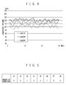
- FIG. 4 is a characteristic drawing illustrating relations between the number of times of starting at various duty ratios of the ISC valve in idling, and maximum value of pressure in the intake pipe 1b.
- the adjust screw 11a of the bypass port 11 was turned to adjust the duty ratio of the ISC valve 8 in idling to 30%, 20% and 12%.
- duty ratio of the ISC valve 8 necessary for keeping the idling engine speed at a specified value, with the bypass port 11 fully closed, is 34%.
- the engine was started 30 times using the recoil starter 2 respectively for the individual apertures of the bypass ports 11, that is, while setting the duty ratio of the ISC valve 8 in idling to 30%, 20% or 12.
- average value of the basic atmospheric pressure was found to be higher in the case with a duty ratio of 20% than the case with a duty ratio of 30%, and was also found to be higher in the case with a duty ratio of 12% than the case with a duty ratio of 20%, yielding values more closer to the atmospheric pressure. It was also found that the smaller the duty ratio in idling, the smaller the variation in the basic atmospheric pressure.
- the aperture of the throttle valve 10 and the aperture of the bypass port 11 in the process of starting using the recoil starter 2 is estimated from the duty ratio of the ISC valve 8 in idling, and based on which the basic atmospheric pressure is corrected to give the atmospheric pressure.
- the idling engine speed is determined by the aperture of the throttle valve 10 (leakage under full closure), the aperture of the ISC valve 8, and the aperture of the bypass port 11, and the aperture (duty ratio) of the ISC valve 8 is controlled so as to keep the idling engine speed at a specified value.
- the larger the aperture (duty ratio) of the ISC valve 8 in idling the relatively smaller the total of the aperture of the throttle valve 10 and the aperture of the bypass port 11 in idling.
- the smaller the aperture (duty ratio) of the ISC valve 8 in idling the relatively larger the total of the aperture of the throttle valve 10 and the aperture of the bypass port 11 in idling.
- the total of the aperture of the throttle valve 10 and the aperture of the bypass port 11 in idling is equal to that observed in the manually cranking with the throttle kept closed.
- the amounts of correction a, b, ⁇ are determined so that values of the basic atmospheric pressure obtained for the individual duty ratios coincide with the atmospheric pressure.
- the amounts of correction a, b, ⁇ may be coefficients for multiplication, or may be additional values for compensating shortage below the atmospheric pressure.
- the larger the duty ratio of the ISC valve 8 in idling the relatively smaller the total of the aperture of the throttle valve 10 and the aperture of the bypass port 11 in idling.
- the state of opening of the intake pipe 1b is close to the fully closed state, and the basic atmospheric pressure tends to be lower than the atmospheric pressure. Accordingly, the amount of correction for more largely correcting the basic atmospheric pressure will be determined, under larger duty ratio of the ISC valve 8 in idling.
- FIG. 6 is a flow chart illustrating processing action executed by the ECM 9 of this embodiment. Note that the flow chart in FIG. 6 illustrates only a part of the processing action (processing action after activation), so that processing action under normal operation (for example, control of fuel injection by the injector 4) is not illustrated.
- This embodiment will explain an exemplary case where an unillustrated additional battery and a starter motor are installed so as to enable both of starting with the aid of the starter motor and starting with the aid of the recoil starter 2.
- step S102 uses data of the pressure in the intake pipe 1b detected by the pressure sensor 6 in a memory, for later use as the atmospheric pressure (step S102), and uses it for controlling fuel injection by the injector 4.
- the maximum value detection unit 9b of the ECM 9 detects the basic atmospheric pressure, that is, a maximum value (which may be a maximum value per se, or may be an average value over a peak area) of the pressure in the intake pipe 1b detected by the pressure sensor 6, within a predetermined range of crank angle after activation (step S104).
- a maximum value which may be a maximum value per se, or may be an average value over a peak area
- the pressure sensor 6 detects the basic atmospheric pressure, that is, a maximum value (which may be a maximum value per se, or may be an average value over a peak area) of the pressure in the intake pipe 1b detected by the pressure sensor 6, within a predetermined range of crank angle after activation (step S104).
- a maximum value which may be a maximum value per se, or may be an average value over a peak area
- a moving average value of the pressure in the intake pipe 1b may be determined for every detection cycle, and the EEPROM may be rewritten only when a moving average value of the pressure in the intake pipe 1b in the latest detection cycle is higher than the moving average value already stored in the EEPROM. In this way, the EEPROM will have stored therein a maximum value of the pressure in the intake pipe 1b (basic atmospheric pressure), within a predetermined range of crank angle after the activation.
- the ECM 9 also detects the aperture of the throttle valve 10 detected by the throttle aperture sensor 7, within a predetermined range of crank angle after the activation (step S104).
- the ECM 9 determines whether the engine 1 is in the idling state or not (step S105).
- step S106 whether the aperture of the throttle valve 10 detected in step S104, that is, the aperture of the throttle valve 10 in the process of manually cranking, is not smaller than the specified value is determined (step S106). While the manually cranking is generally conducted while keeping the throttle almost closed, some user may start the engine using the recoil starter 2, while keeping the throttle opened. Note that the decision may alternatively be made on whether the average aperture of the throttle valve 10 within a predetermined range of crank angle after the activation of the ECM 9 reaches the specified value or above, or may be made whether the aperture of the throttle valve 10 reaches the specified value or above even only once within a predetermined range of crank angle after the activation of the ECM 9.
- the ECM 9 reads the amount of correction out from the map stored in the storage unit 9d, depending on the duty ratio of the ISC valve 8 determined by the idling control unit 9b (step S107).
- the basic atmospheric pressure detected in step S104 is then corrected using the amount of correction, and stored in a memory for later use as the atmospheric pressure (step S108), and used thereafter for controlling fuel injection by the injector 4.
- step S104 if the aperture of the throttle valve 10 detected in step S104 is not smaller than a specified value, the intake pipe 1b in the process of manually cranking is in the opened state, and the pressure in the intake pipe 1b coincides with the atmospheric pressure.
- the basic atmospheric pressure detected in step S104 is then stored into the memory for later use as the atmospheric pressure in an intact form without correction (step S109), and used thereafter for controlling fuel injection by the injector 4.
- the present invention yields a more accurate atmospheric pressure, since the invention was configured to estimate the state of opening of the intake pipe 1b during the manually cranking based on the duty ratio of the ISC valve 8 in idling, and to correspondingly correct the maximum value of pressure in the intake pipe 1b.
- the correction for determining the atmospheric pressure is not available until the idling state is reached after the starting by the recoil starter 2. Accordingly, a possible alternative method may be such that the duty ratio of the ISC valve 8 in idling in the previous operation is stored, and if the basic atmospheric pressure is detected in step S104, the correction is made using the amount of correction corresponded to the duty ratio in the previous operation.
- the adjust screw 11a is adjusted between the previous operation and the present operation, but it is a rare case.
- a more exact atmospheric pressure may be obtained by correcting the pressure in the intake pipe.
Landscapes
- Engineering & Computer Science (AREA)
- Chemical & Material Sciences (AREA)
- Combustion & Propulsion (AREA)
- Mechanical Engineering (AREA)
- General Engineering & Computer Science (AREA)
- Electrical Control Of Air Or Fuel Supplied To Internal-Combustion Engine (AREA)
- Combined Controls Of Internal Combustion Engines (AREA)
Abstract
Description
- This application is based upon and claims the benefit of priority of the prior Japanese Patent Application No.
2012-070001, filed on March 26, 2012 - The present invention relates to an engine start control system which is convenient when used for manually starting an engine with the aid of a recoil starter or the like.
- Some types of engines used for outboard motor employ an ECM (Engine Control Module) for controlling fuel injection by an injector. The ECM in this case is configured to use the atmospheric pressure as one parameter for regulating the fuel injection.
- Patent Document 1 discloses a configuration aimed at detecting the atmospheric pressure without using the atmospheric pressure sensor, wherein the atmospheric pressure is detected by a pressure sensor for detecting air pressure in an intake pipe, based on a pressure detection signal of the pressure sensor detected when the control unit (ECM) is powered ON, while a crankshaft stays still.
- In particular, marine vessels hardly encounter a situation such that the atmospheric pressure sharply changes (for example, travel towards highlands) in a single operation, so that information of the atmospheric pressure only at the start of operation will suffice. Accordingly, there will be no need of equipping a dedicated atmospheric pressure sensor, if the atmospheric pressure may be known from the pressure in the intake pipe as described in Patent Document 1, and this will give a large cost merit.
- [Patent Document 1] Japanese Laid-Open Patent Publication No.
H11-247706 - The configuration described in Patent Document 1 is, however, premised on installing a battery. In a configuration without the battery, the ECM will be activated as powered from a generator which operates in association with rotation of a crankshaft of the engine. In other words, the ECM will not be activated unless the crankshaft rotates, so that it is unable to detect the atmospheric pressure based on the pressure detection signal of the pressure sensor, when the crankshaft stays still, as described in Patent Document 1.
- For the configuration without the battery, there is now one possible idea of determining the atmospheric pressure, by detecting the maximum value of pressure in the intake pipe, when the ECM is powered from the manually-cranked generator in the process of starting using the recoil starter. In the manually cranking, that is, in a period before the engine starts to rotate under its own power, the pressure in the intake pipe becomes negative relative to the atmospheric pressure in the intake process, and peaks at the time of switching from the exhaust process to the intake process, showing the maximum value close to the atmospheric pressure.
- By the way, while having described that the maximum value of pressure in the intake pipe during manually cranking is close to the atmospheric pressure, a shift from the atmospheric pressure actually occurs depending on the state of opening of the intake pipe involved therein. The larger the state of opening of the intake pipe during manually cranking, the larger the volume of air fed thereto, and the closer the maximum value of pressure in the intake pipe to the atmospheric pressure. Conversely, the closer the state of opening to the closed state, the smaller the volume of air fed thereto, and the more lower the maximum value of pressure in the intake pipe than the atmospheric pressure.
- Difference in the state of opening of the intake pipe during the manually cranking is typically ascribable to the following factors. The manually cranking is generally carried out while keeping the throttle almost closed, where there is some variation from engine to engine, in the leakage from fully-closed throttle valve. Even the same engine may vary in the leakage from fully-closed throttle valve with time. In some configuration, the intake pipe has a bypass port connected to the downstream side of the throttle valve. The bypass port has an adjust screw attached thereto, adjustment of which changes the aperture of the bypass port, and allows regulation of volume of air fed to the intake pipe.
- With the issues described in the above, the present invention was conceived and an object of which is to obtain the atmospheric pressure in a more exact manner, when the pressure detected in the intake pipe during the manually cranking is assumed as the atmospheric pressure.
- According to the present invention, there is provided an engine start control system which includes a manual starter which allows manual rotation of a crankshaft of an engine; a generator which operates in association with rotation of the crankshaft; an electronic fuel injector which feeds a fuel to the engine; an engine control device which operates using electric power generated by the generator, and controls the electronic fuel injector; a pressure detection section which detects pressure in an intake pipe on the downstream side of a throttle valve of the engine; and an air regulator which feeds air to the intake pipe on the downstream side of the throttle valve. The engine control device includes a maximum value detection section which detects, in the process of starting by the manual starter, a maximum value of pressure in the intake pipe detected by the pressure detection section, within a predetermined range of crank angle after activation of the engine control device; an idling control section which controls the air regulator to thereby keep the idling engine speed at a specified value; and a correction section which corrects the maximum value of pressure in the intake pipe detected by the maximum value detection section to the atmospheric pressure, based on a control volume of the air regulator made by the idling control section.
- According to another aspect of the present invention, there is provided the engine start control system, wherein the control volume of the air regulator by the idling control section is preliminarily correlated with the amount of correction made on the maximum value of pressure in the intake pipe, and the correction section performs the correction using the amount of correction.
- According to another aspect of the present invention, there is provided the engine start control system, which further includes a throttle aperture detection section which detects aperture of the throttle valve. The correction section does not perform the correction, if the aperture of the throttle valve detected by the throttle aperture detection section is not smaller than the specified value, within a predetermined range of crank angle after activation of the engine control device.
-
-
FIG. 1 is a drawing illustrating a schematic configuration of an engine start control system of one embodiment; -
FIG. 2 is a drawing illustrating an intake structure of an engine; -
FIG. 3 is a drawing illustrating characteristics regarding voltage generated by a generator, pressure in an intake pipe, engine speed, and characteristics of an ECM power source, in the process of starting using a recoil starter; -
FIG. 4 is a characteristic drawing illustrating relations between the number of times of starting under various values of duty ratio of an ISC valve in idling, and maximum value of pressure in the intake pipe; -
FIG. 5 is a drawing illustrating an exemplary map preliminarily correlating duty ratio of the ISC valve in idling with the amount of correction to be made on the basic atmospheric pressure; and -
FIG. 6 is a flow chart illustrating processing action executed by the ECM of the embodiment. - Preferred embodiments of the present invention will be explained, referring to the attached drawings.
-
FIG. 1 is a drawing illustrating a schematic configuration of an engine start control system of one embodiment.FIG. 2 is a drawing illustrating an intake structure of an engine 1. Note thatFIG. 1 only illustrates constituents around the engine 1 and an ECM 9 necessary for applying the present invention, leaving the other constituents not illustrated. - Reference numeral 1 denotes an engine as an internal combustion engine.
- Reference numeral 2 denotes a recoil starter which functions as a manual starter, configured to induce rotation of a
crankshaft 1a (seeFIG. 2 ) of the engine 1, by pulling by hand arope 2a wound around a pulley. Reference numeral 3 denotes a generator which is driven by rotation of thecrankshaft 1a of the engine 1. -
Reference numeral 4 denotes an injector which functions as an electronic fuel injector, and is attached to anintake pipe 1b (seeFIG. 2 ) of the engine 1. Theinjector 4 feeds a fuel, fed from an unillustrated fuel pump, by injecting it into theintake pipe 1b, according to a driving signal received from the ECM 9. - Reference numeral 5 denotes an engine speed sensor which detects engine speed based on time necessary to reach a predetermined crank angle.
-
Reference numeral 6 is a pressure sensor which functions as a pressure detection section, and detects pressure in theintake pipe 1b on the downstream side of a throttle valve 10 (seeFIG. 2 ). -
Reference numeral 7 denotes a throttle aperture sensor which functions as a throttle aperture detection section, and detects aperture of thethrottle valve 10. -
Reference numeral 8 denotes an idle speed control valve (referred to as "ISC valve", hereinafter) which functions as an air regulator, and feeds air into theintake pipe 1b on the downstream side of thethrottle valve 10. - Reference numeral 9 denotes an ECM which functions as a engine control device, and is configured by a CPU, a RAM, a ROM and so forth which function as a maximum
value detection unit 9a, anidling control unit 9b, acorrection unit 9c and astorage unit 9d. The ECM 9 operates as powered by the generator 3. - In the maximum
value detection unit 9a, a maximum value of pressure in theintake pipe 1b detected by the pressure sensor 6 (referred to as "basic atmospheric pressure", hereinafter) is detected, within a predetermined range of crank angle after the activation of the ECM 9, in the process of starting using the recoil starter 2. - The
idling control unit 9b takes part in feedback control of theISC valve 8, based on the engine speed detected by the engine speed sensor 5, to thereby keep the idling engine speed at a specified value. - The
correction unit 9c corrects the basic atmospheric pressure based on control volume of theISC valve 8 by theidling control unit 9b, which is a duty ratio of theISC valve 8 in idling in this embodiment, to thereby adjust it to the atmospheric pressure. - The
storage unit 9d stores a map in which the duty ratio of theISC valve 8 in idling is correlated with the amount of correction to be made on the basic atmospheric pressure. - As illustrated in
FIG. 2 , theintake pipe 1b of the engine 1 is provided with thethrottle valve 10. The aperture of thethrottle valve 10 in the closed state corresponds to leakage from the fully-closedthrottle valve 10. - There is also provided the
ISC valve 8 which feeds air into theintake pipe 1b on the downstream side of thethrottle valve 10. Theidling control unit 9b of the ECM 9 determines a ratio of valve opening of theISC valve 8 based on duty control of a solenoid (electromagnetic valve) 8a. For an exemplary case where an ON/OFF signal having a cycle time of 100 msec is repeated, and the ON duration accounts for 50 msec out of 100 msec, then the duty ratio will be 50%. Theidling control unit 9b of the ECM 9 keeps the idling engine speed at a specified value, by increasing the duty ratio of the ISC valve 8 (by increasing the aperture of the ISC valve 8) so as to increase the idling engine speed when the idling engine speed slows down, and conversely, by decreasing the duty ratio of the ISC valve 8 (by decreasing the aperture of the ISC valve 8) so as to decrease the idling engine speed when the idling engine speed increases. - There is also provided a bypass port 11 connected on the downstream side of the
throttle valve 10. The bypass port 11 has an adjustscrew 11a attached thereto, adjustment of which may change the aperture of the bypass port 11, and may change the volume of air flowing through theintake pipe 1b. Note that, in reality, the idling engine speed is not adjustable by the adjustscrew 11a, since the amount of change in air volume made by the adjustscrew 11a is cancelled by theISC valve 8, and so that the idling engine speed will not deviate from the specified value. What is controlled by the adjustscrew 11a is the aperture of theISC valve 8, that is, the duty ratio of theISC valve 8. - As described in the above, air is fed through the
throttle valve 10, theISC valve 8 and the bypass port 11, into a combustion chamber of the engine 1. Also the idling engine speed is determined by the aperture of the throttle valve 10 (leakage under full closure), the aperture of theISC valve 8, and the aperture of the bypass port 11. The aperture (duty ratio) of theISC valve 8 is controlled, so as to keep the idling engine speed constant. - Next, characteristics of voltage generated by the generator 3 in the process of starting using the recoil starter 2 (output voltage of the generator 3), pressure in the
intake pipe 1b (output of the pressure sensor 6), engine speed (rotation output of the engine speed sensor 5), and an ECM power source are shown inFIG. 3 . - As indicated by a
characteristic curve 23 inFIG. 3 , the engine speed appears as a result of manually cranking in the process of starting using the recoil starter 2. In association therewith, the generator 3 operates to elevate the voltage generation as indicated by acharacteristic curve 21. When the voltage generation of the generator 3 exceeds a predetermined level, the ECM 9 activates as indicated by acharacteristic curve 24. When combustion occurs thereafter as a result of ignition in a specified timing beyond the compression dead top center (first explosion), the engine 1 starts to thereby elevate the engine speed. - Now, in the manually cranking, that is, in a period before the engine starts to rotate under its own power, the pressure in the
intake pipe 1b becomes negative relative to the atmospheric pressure in the intake process, as indicated by acharacteristic curve 22, and peaks at the time of switching from the exhaust process to the intake process, showing the maximum value close to the atmospheric pressure. Note that the pressure in theintake pipe 1b, once the engine 1 began to rotate under its own power, becomes negative relative to the atmospheric pressure, also the maximum value thereof does not reach the atmospheric pressure, rather than coming into agreement with the atmospheric pressure. - As described in the above, in the manually cranking, while the maximum value of pressure in the
intake pipe 1b (basic atmospheric pressure) is close to the atmospheric pressure, a shift from the atmospheric pressure actually occurs depending on the state of opening of theintake pipe 1b involved therein. The larger the state of opening of theintake pipe 1b during the manually cranking, the larger the volume of air fed thereto, and the closer the basic atmospheric pressure to the atmospheric pressure. Conversely, the closer the state of opening to the closed state, the smaller the volume of air fed thereto, and the more lower the basic atmospheric pressure than the atmospheric pressure. The difference in the state of opening of theintake pipe 1b in the manually cranking is typically ascribable to that there is some variation in the leakage under full closure of thethrottle valve 10 among the engines 1, that the leakage under full closure may vary with time even in the same engine 1, and that the aperture of the bypass port 11 varies as a result of adjustment of the adjustscrew 11a. - As illustrated in
FIG. 4 , the present inventors confirmed the maximum value of the pressure in theintake pipe 1b, during the manually cranking (immediately after activation of the ECM 9).FIG. 4 is a characteristic drawing illustrating relations between the number of times of starting at various duty ratios of the ISC valve in idling, and maximum value of pressure in theintake pipe 1b. - In this experiment, the adjust
screw 11a of the bypass port 11 was turned to adjust the duty ratio of theISC valve 8 in idling to 30%, 20% and 12%. The smaller the aperture of the bypass port 11, the larger the duty ratio of theISC valve 8 in idling, whereas the larger the aperture of the bypass port 11, the smaller the duty ratio of theISC valve 8 in idling. Note that duty ratio of theISC valve 8 necessary for keeping the idling engine speed at a specified value, with the bypass port 11 fully closed, is 34%. - The engine was started 30 times using the recoil starter 2 respectively for the individual apertures of the bypass ports 11, that is, while setting the duty ratio of the
ISC valve 8 in idling to 30%, 20% or 12. The manually cranking was conducted while keeping the throttle almost closed, with theISC valve 8 fully opened (duty ratio=100%). As a consequence, as illustrated in the drawing, average value of the basic atmospheric pressure was found to be higher in the case with a duty ratio of 20% than the case with a duty ratio of 30%, and was also found to be higher in the case with a duty ratio of 12% than the case with a duty ratio of 20%, yielding values more closer to the atmospheric pressure. It was also found that the smaller the duty ratio in idling, the smaller the variation in the basic atmospheric pressure. Assuming now, for compensating shortage of number of samples, that the measured values normally distribute with a variation of 3σ, the variation was found to be 4.7% relative to the average value for a duty ratio of 30%, and was found to be 1.2% relative to the average value for a duty ratio of 12%. No difference was found in stability of idling, under different duty ratios of theISC valve 8. - In the engine start control system applied by the present invention, the aperture of the
throttle valve 10 and the aperture of the bypass port 11 in the process of starting using the recoil starter 2 is estimated from the duty ratio of theISC valve 8 in idling, and based on which the basic atmospheric pressure is corrected to give the atmospheric pressure. - As descried in the above, the idling engine speed is determined by the aperture of the throttle valve 10 (leakage under full closure), the aperture of the
ISC valve 8, and the aperture of the bypass port 11, and the aperture (duty ratio) of theISC valve 8 is controlled so as to keep the idling engine speed at a specified value. In other words, the larger the aperture (duty ratio) of theISC valve 8 in idling, the relatively smaller the total of the aperture of thethrottle valve 10 and the aperture of the bypass port 11 in idling. Conversely, the smaller the aperture (duty ratio) of theISC valve 8 in idling, the relatively larger the total of the aperture of thethrottle valve 10 and the aperture of the bypass port 11 in idling. The total of the aperture of thethrottle valve 10 and the aperture of the bypass port 11 in idling is equal to that observed in the manually cranking with the throttle kept closed. - Now, as illustrated in
FIG. 5 , based on experimental values obtained from an engine of the same type and of same specifications, duty ratios X1, X2, ··· of theISC valve 8 in idling and the amounts of correction a, b, ··· with respect to the basic atmospheric pressure are mapped, and stored in thestorage unit 9d. More specifically, as illustrated inFIG. 4 , the duty ratio of theISC valve 8 in idling is adjusted to X1, X2, ···, and the basic atmospheric pressure is confirmed for each state. The manually cranking is conducted while keeping the throttle almost closed, and with theISC valve 8 fully opened (duty ratio=100%). The amounts of correction a, b, ··· are determined so that values of the basic atmospheric pressure obtained for the individual duty ratios coincide with the atmospheric pressure. The amounts of correction a, b, ··· may be coefficients for multiplication, or may be additional values for compensating shortage below the atmospheric pressure. - As is understood from
FIG. 4 , the larger the duty ratio of theISC valve 8 in idling, the relatively smaller the total of the aperture of thethrottle valve 10 and the aperture of the bypass port 11 in idling. In other words, in the manually cranking conducted with the throttle kept closed, the state of opening of theintake pipe 1b is close to the fully closed state, and the basic atmospheric pressure tends to be lower than the atmospheric pressure. Accordingly, the amount of correction for more largely correcting the basic atmospheric pressure will be determined, under larger duty ratio of theISC valve 8 in idling. -
FIG. 6 is a flow chart illustrating processing action executed by the ECM 9 of this embodiment. Note that the flow chart inFIG. 6 illustrates only a part of the processing action (processing action after activation), so that processing action under normal operation (for example, control of fuel injection by the injector 4) is not illustrated. - This embodiment will explain an exemplary case where an unillustrated additional battery and a starter motor are installed so as to enable both of starting with the aid of the starter motor and starting with the aid of the recoil starter 2.
- The ECM 9, when activated upon being powered, determines by which of the starter motor or the recoil starter 2 it was activated (step S101). If the activation was made by the starter motor, the ECM 9 may be powered from a battery and may be activated, by pressing an unillustrated started switch. On the other hand, if the activation was made by the recoil starter 2, the ECM 9 may be powered from the generator 3 as a result of manually cranking, and may be activated. Accordingly, the ECM 9 may determine whether the activation was made by the starter motor or the recoil starter 2, by determining from which port the electric power was fed.
- In the activation with the aid of the starter motor, since the ECM 9 activates immediately upon being powered from the battery, so that the pressure in the
intake pipe 1b when thecrankshaft 1a stays still is detectable by thepressure sensor 6. The pressure in theintake pipe 1b when thecrankshaft 1a stays still is equal to the atmospheric pressure, so that the ECM 9 stores data of the pressure in theintake pipe 1b detected by thepressure sensor 6 in a memory, for later use as the atmospheric pressure (step S102), and uses it for controlling fuel injection by theinjector 4. - In the activation with the aid of the recoil starter 2, the ECM 9 fully opens the ISC valve 8 (duty ratio=100%) (step S103). This is for the purpose of making the pressure in the
intake pipe 1b closer as possible to the atmospheric pressure. - The maximum
value detection unit 9b of the ECM 9 then detects the basic atmospheric pressure, that is, a maximum value (which may be a maximum value per se, or may be an average value over a peak area) of the pressure in theintake pipe 1b detected by thepressure sensor 6, within a predetermined range of crank angle after activation (step S104). For example, an EEPROM in the ECM 9 is rewritten with data of pressure in theintake pipe 1b detected for the first time by thepressure sensor 6. Thereafter, until a predetermined level of crank angle is reached, the EEPEOM is rewritten with data of pressure in theintake pipe 1b sequentially detected by thepressure sensor 6, only when the newly detected pressure is higher than the already stored pressure. For example, a moving average value of the pressure in theintake pipe 1b may be determined for every detection cycle, and the EEPROM may be rewritten only when a moving average value of the pressure in theintake pipe 1b in the latest detection cycle is higher than the moving average value already stored in the EEPROM. In this way, the EEPROM will have stored therein a maximum value of the pressure in theintake pipe 1b (basic atmospheric pressure), within a predetermined range of crank angle after the activation. - The ECM 9 also detects the aperture of the
throttle valve 10 detected by thethrottle aperture sensor 7, within a predetermined range of crank angle after the activation (step S104). - After the engine 1 began to rotate under its own power, the ECM 9 determines whether the engine 1 is in the idling state or not (step S105).
- If the engine 1 was found to be in the idling state, whether the aperture of the
throttle valve 10 detected in step S104, that is, the aperture of thethrottle valve 10 in the process of manually cranking, is not smaller than the specified value is determined (step S106). While the manually cranking is generally conducted while keeping the throttle almost closed, some user may start the engine using the recoil starter 2, while keeping the throttle opened. Note that the decision may alternatively be made on whether the average aperture of thethrottle valve 10 within a predetermined range of crank angle after the activation of the ECM 9 reaches the specified value or above, or may be made whether the aperture of thethrottle valve 10 reaches the specified value or above even only once within a predetermined range of crank angle after the activation of the ECM 9. - If the aperture of the
throttle valve 10 detected in step S104 is smaller than a specified value, the ECM 9 reads the amount of correction out from the map stored in thestorage unit 9d, depending on the duty ratio of theISC valve 8 determined by the idlingcontrol unit 9b (step S107). The basic atmospheric pressure detected in step S104 is then corrected using the amount of correction, and stored in a memory for later use as the atmospheric pressure (step S108), and used thereafter for controlling fuel injection by theinjector 4. - On the contrary, if the aperture of the
throttle valve 10 detected in step S104 is not smaller than a specified value, theintake pipe 1b in the process of manually cranking is in the opened state, and the pressure in theintake pipe 1b coincides with the atmospheric pressure. The basic atmospheric pressure detected in step S104 is then stored into the memory for later use as the atmospheric pressure in an intact form without correction (step S109), and used thereafter for controlling fuel injection by theinjector 4. - Note that, for the case of starting with the aid of the recoil starter 2 in this embodiment, the
ISC valve 8 during the manually cranking was kept fully opened (duty ratio=100%) (step S103). This is for the purpose of making the pressure in theintake pipe 1b closer as possible to the atmospheric pressure. It is, however, not always necessary to keep theISC valve 8 fully opened (duty ratio=100%), and it suffices that theISC valve 8 is set to a constant duty ratio during the manually cranking. In the process of preliminarily obtaining the duty ratios X1, X2, ··· of theISC valve 8 in idling and the amounts of correction a, b, ··· with respect to the basic atmospheric pressure based on experimental values, the experiment is of course conducted while setting values of the duty ratio similar to those in step S103. - As described in the above, for the case where the pressure in the
intake pipe 1b is detected in the process of manually cranking and is used as the atmospheric pressure, the present invention yields a more accurate atmospheric pressure, since the invention was configured to estimate the state of opening of theintake pipe 1b during the manually cranking based on the duty ratio of theISC valve 8 in idling, and to correspondingly correct the maximum value of pressure in theintake pipe 1b. - Having described the present invention referring to various embodiments, the present invention is by no means limited to these embodiment, and may be modified within the scope of the present invention.
- For example, in the embodiment described in the above, the correction for determining the atmospheric pressure is not available until the idling state is reached after the starting by the recoil starter 2. Accordingly, a possible alternative method may be such that the duty ratio of the
ISC valve 8 in idling in the previous operation is stored, and if the basic atmospheric pressure is detected in step S104, the correction is made using the amount of correction corresponded to the duty ratio in the previous operation. Of course, there is no denying that the adjustscrew 11a is adjusted between the previous operation and the present operation, but it is a rare case. An advantage of making the correction possible without waiting for the idling state surpasses. - According to the present invention, for the case where the pressure in the intake pipe is detected in the process of manually cranking and is used as the atmospheric pressure, a more exact atmospheric pressure may be obtained by correcting the pressure in the intake pipe.
- It should be noted that the above embodiments merely illustrate concrete examples of implementing the present invention, and the technical scope of the present invention is not to be construed in a restrictive manner by these embodiments. That is, the present invention may be implemented in various forms without departing from the technical spirit or main features thereof.
Claims (3)
- An engine start control system comprising:a manual starter which allows manual rotation of a crankshaft of an engine;a generator which operates in association with rotation of the crankshaft;an electronic fuel injector which feeds a fuel to the engine;an engine control device which operates using electric power generated by the generator, and controls the electronic fuel injector;a pressure detection section which detects pressure in an intake pipe on the downstream side of a throttle valve of the engine; andan air regulator which feeds air to the intake pipe on the downstream side of the throttle valve,the engine control device comprising:a maximum value detection section which detects, in the process of starting by the manual starter, a maximum value of pressure in the intake pipe detected by the pressure detection section, within a predetermined range of crank angle after activation of the engine control device;an idling control section which controls the air regulator to thereby keep the idling engine speed at a specified value; anda correction section which corrects the maximum value of pressure in the intake pipe detected by the maximum value detection section to the atmospheric pressure, based on a control volume of the air regulator made by the idling control section.
- The engine start control system according to Claim 1,
wherein the control volume of the air regulator by the idling control section is preliminarily correlated with the amount of correction made on the maximum value of pressure in the intake pipe, and
the correction section performs the correction using the amount of correction. - The engine start control system according to Claim 1, further comprising:a throttle aperture detection section which detects aperture of the throttle valve: andthe correction section does not perform the correction, if the aperture of the throttle valve detected by the throttle aperture detection section is not smaller than the specified value, within a predetermined range of crank angle after activation of the engine control device.
Applications Claiming Priority (1)
| Application Number | Priority Date | Filing Date | Title |
|---|---|---|---|
| JP2012070001A JP5821737B2 (en) | 2012-03-26 | 2012-03-26 | Engine start control system |
Publications (3)
| Publication Number | Publication Date |
|---|---|
| EP2644881A2 true EP2644881A2 (en) | 2013-10-02 |
| EP2644881A3 EP2644881A3 (en) | 2014-12-10 |
| EP2644881B1 EP2644881B1 (en) | 2017-10-18 |
Family
ID=47900722
Family Applications (1)
| Application Number | Title | Priority Date | Filing Date |
|---|---|---|---|
| EP13158631.5A Active EP2644881B1 (en) | 2012-03-26 | 2013-03-11 | Engine start control system |
Country Status (3)
| Country | Link |
|---|---|
| US (1) | US9347417B2 (en) |
| EP (1) | EP2644881B1 (en) |
| JP (1) | JP5821737B2 (en) |
Families Citing this family (7)
| Publication number | Priority date | Publication date | Assignee | Title |
|---|---|---|---|---|
| JP5676708B1 (en) * | 2013-08-29 | 2015-02-25 | 三菱電機株式会社 | Outboard motor atmospheric pressure estimation device |
| JP6323112B2 (en) | 2014-03-27 | 2018-05-16 | スズキ株式会社 | Engine control system |
| US10436138B2 (en) * | 2017-07-24 | 2019-10-08 | Ford Global Technologies, Llc | Systems and methods for diagnosing a vehicle engine intake manifold and exhaust system |
| US10641214B2 (en) * | 2018-02-15 | 2020-05-05 | Ford Global Technologies, Llc | System and method for diagnosing an EGR system |
| US11319915B2 (en) | 2020-06-11 | 2022-05-03 | Kohler Co. | Engine system, and method of starting the engine |
| JP7703285B2 (en) * | 2022-02-07 | 2025-07-07 | マーレ インターナショナル ゲゼルシャフト ミット ベシュレンクテル ハフツング | Atmospheric pressure detection device for multi-cylinder engines |
| JP7718437B2 (en) * | 2023-02-06 | 2025-08-05 | トヨタ自動車株式会社 | Control device for internal combustion engine |
Citations (1)
| Publication number | Priority date | Publication date | Assignee | Title |
|---|---|---|---|---|
| JPH11247706A (en) | 1998-03-02 | 1999-09-14 | Suzuki Motor Corp | Pressure detector for internal combustion engine |
Family Cites Families (13)
| Publication number | Priority date | Publication date | Assignee | Title |
|---|---|---|---|---|
| DE3914654A1 (en) * | 1988-05-06 | 1989-11-16 | Mitsubishi Electric Corp | DEVICE FOR MONITORING AN INTERNAL COMBUSTION ENGINE |
| JPH07180596A (en) * | 1993-12-24 | 1995-07-18 | Nippondenso Co Ltd | Atmospheric pressure detector for engine control |
| JPH0874647A (en) * | 1994-09-06 | 1996-03-19 | Daihatsu Motor Co Ltd | Detecting method for atmospheric pressure |
| US6445996B1 (en) * | 1999-12-22 | 2002-09-03 | Cummins Engine Company, Inc. | Method and system for dynamically estimating atmospheric air pressure ambient to an internal combustion engine |
| JP2003176749A (en) * | 2001-10-04 | 2003-06-27 | Denso Corp | Atmospheric pressure detection device for internal combustion engine |
| US6752128B2 (en) * | 2002-06-12 | 2004-06-22 | Denso Corporation | Intake system failure detecting device and method for engines |
| JP2008163790A (en) * | 2006-12-27 | 2008-07-17 | Toyota Motor Corp | Control device for internal combustion engine |
| JP2009024540A (en) * | 2007-07-18 | 2009-02-05 | Kokusan Denki Co Ltd | Engine starting device |
| JP2009185717A (en) * | 2008-02-06 | 2009-08-20 | Yamaha Motor Co Ltd | Fuel injection control device and vehicle |
| CN102308075B (en) | 2009-02-06 | 2014-11-26 | 本田技研工业株式会社 | Atmospheric pressure estimation device |
| JP4884507B2 (en) * | 2009-09-25 | 2012-02-29 | 三菱電機株式会社 | Engine fuel injection control device |
| JP5307851B2 (en) * | 2011-05-19 | 2013-10-02 | 三菱電機株式会社 | Engine fuel pump control device |
| JP5825167B2 (en) * | 2012-03-26 | 2015-12-02 | スズキ株式会社 | Engine start control system |
-
2012
- 2012-03-26 JP JP2012070001A patent/JP5821737B2/en active Active
-
2013
- 2013-03-11 EP EP13158631.5A patent/EP2644881B1/en active Active
- 2013-03-18 US US13/846,022 patent/US9347417B2/en active Active
Patent Citations (1)
| Publication number | Priority date | Publication date | Assignee | Title |
|---|---|---|---|---|
| JPH11247706A (en) | 1998-03-02 | 1999-09-14 | Suzuki Motor Corp | Pressure detector for internal combustion engine |
Also Published As
| Publication number | Publication date |
|---|---|
| JP5821737B2 (en) | 2015-11-24 |
| US9347417B2 (en) | 2016-05-24 |
| EP2644881B1 (en) | 2017-10-18 |
| JP2013199915A (en) | 2013-10-03 |
| EP2644881A3 (en) | 2014-12-10 |
| US20130247878A1 (en) | 2013-09-26 |
Similar Documents
| Publication | Publication Date | Title |
|---|---|---|
| EP2644881B1 (en) | Engine start control system | |
| JP4442623B2 (en) | Engine control device | |
| CN102200067B (en) | For fuel supply control apparatus and the fuel supply control method thereof of internal-combustion engine | |
| EP2357340B1 (en) | Device and method for controlling timing at which ignition is stopped when internal combustion engine becomes stopped | |
| KR20130107223A (en) | Control unit for variable valve timing mechanism and control method for variable valve timing mechanism | |
| EP1382820A2 (en) | Engine air-fuel ratio control method with venturi type fuel supply device and fuel control appliance including the method | |
| US7000594B2 (en) | Electronic control unit for two-cycle internal combustion engine with exhaust control valve | |
| US6308698B1 (en) | Method and apparatus for controlling fuel injection in diesel engine | |
| US6843225B1 (en) | Controller for control at engine startup | |
| US9145861B2 (en) | Engine start control system | |
| US8573179B2 (en) | Engine ignition control apparatus | |
| JP2008095655A (en) | Engine control device | |
| US7252057B2 (en) | Apparatus and method for controlling internal combustion engine | |
| KR20200123667A (en) | Method to ensure negative pressure of brake booster | |
| JP2008095519A (en) | Engine stop control device | |
| JP4661747B2 (en) | Engine stop control device | |
| US11193429B2 (en) | Driving control device for fuel pump and fuel supply apparatus | |
| JPS61169642A (en) | Control device for number of idle revolutions of engine | |
| CN110462191B (en) | Control device for vehicle engine | |
| JPH06249117A (en) | Engine idle speed controller | |
| JP2003035169A (en) | Control device for in-cylinder injection internal combustion engine | |
| JPH11107824A (en) | Engine control device | |
| JPH11182301A (en) | Idle speed control device for internal combustion engine | |
| JP2002021609A (en) | Fuel injection amount control device for internal combustion engine | |
| JPH0942018A (en) | Fuel injection amount control device for internal combustion engine |
Legal Events
| Date | Code | Title | Description |
|---|---|---|---|
| PUAI | Public reference made under article 153(3) epc to a published international application that has entered the european phase |
Free format text: ORIGINAL CODE: 0009012 |
|
| AK | Designated contracting states |
Kind code of ref document: A2 Designated state(s): AL AT BE BG CH CY CZ DE DK EE ES FI FR GB GR HR HU IE IS IT LI LT LU LV MC MK MT NL NO PL PT RO RS SE SI SK SM TR |
|
| AX | Request for extension of the european patent |
Extension state: BA ME |
|
| PUAL | Search report despatched |
Free format text: ORIGINAL CODE: 0009013 |
|
| AK | Designated contracting states |
Kind code of ref document: A3 Designated state(s): AL AT BE BG CH CY CZ DE DK EE ES FI FR GB GR HR HU IE IS IT LI LT LU LV MC MK MT NL NO PL PT RO RS SE SI SK SM TR |
|
| AX | Request for extension of the european patent |
Extension state: BA ME |
|
| RIC1 | Information provided on ipc code assigned before grant |
Ipc: F02N 11/08 20060101ALI20141105BHEP Ipc: F02N 3/00 20060101AFI20141105BHEP |
|
| 17P | Request for examination filed |
Effective date: 20150122 |
|
| RBV | Designated contracting states (corrected) |
Designated state(s): AL AT BE BG CH CY CZ DE DK EE ES FI FR GB GR HR HU IE IS IT LI LT LU LV MC MK MT NL NO PL PT RO RS SE SI SK SM TR |
|
| REG | Reference to a national code |
Ref country code: DE Ref legal event code: R079 Ref document number: 602013028004 Country of ref document: DE Free format text: PREVIOUS MAIN CLASS: F02N0003000000 Ipc: F02N0011040000 |
|
| RIC1 | Information provided on ipc code assigned before grant |
Ipc: F02N 19/00 20100101ALI20170328BHEP Ipc: F02N 3/00 20060101ALI20170328BHEP Ipc: F02N 11/04 20060101AFI20170328BHEP Ipc: F02N 11/08 20060101ALI20170328BHEP |
|
| GRAP | Despatch of communication of intention to grant a patent |
Free format text: ORIGINAL CODE: EPIDOSNIGR1 |
|
| STAA | Information on the status of an ep patent application or granted ep patent |
Free format text: STATUS: GRANT OF PATENT IS INTENDED |
|
| INTG | Intention to grant announced |
Effective date: 20170516 |
|
| GRAS | Grant fee paid |
Free format text: ORIGINAL CODE: EPIDOSNIGR3 |
|
| GRAA | (expected) grant |
Free format text: ORIGINAL CODE: 0009210 |
|
| STAA | Information on the status of an ep patent application or granted ep patent |
Free format text: STATUS: THE PATENT HAS BEEN GRANTED |
|
| AK | Designated contracting states |
Kind code of ref document: B1 Designated state(s): AL AT BE BG CH CY CZ DE DK EE ES FI FR GB GR HR HU IE IS IT LI LT LU LV MC MK MT NL NO PL PT RO RS SE SI SK SM TR |
|
| REG | Reference to a national code |
Ref country code: GB Ref legal event code: FG4D |
|
| REG | Reference to a national code |
Ref country code: CH Ref legal event code: EP |
|
| REG | Reference to a national code |
Ref country code: AT Ref legal event code: REF Ref document number: 938178 Country of ref document: AT Kind code of ref document: T Effective date: 20171115 Ref country code: IE Ref legal event code: FG4D |
|
| REG | Reference to a national code |
Ref country code: DE Ref legal event code: R096 Ref document number: 602013028004 Country of ref document: DE |
|
| REG | Reference to a national code |
Ref country code: NL Ref legal event code: MP Effective date: 20171018 |
|
| REG | Reference to a national code |
Ref country code: LT Ref legal event code: MG4D |
|
| REG | Reference to a national code |
Ref country code: AT Ref legal event code: MK05 Ref document number: 938178 Country of ref document: AT Kind code of ref document: T Effective date: 20171018 |
|
| PG25 | Lapsed in a contracting state [announced via postgrant information from national office to epo] |
Ref country code: NL Free format text: LAPSE BECAUSE OF FAILURE TO SUBMIT A TRANSLATION OF THE DESCRIPTION OR TO PAY THE FEE WITHIN THE PRESCRIBED TIME-LIMIT Effective date: 20171018 |
|
| PG25 | Lapsed in a contracting state [announced via postgrant information from national office to epo] |
Ref country code: FI Free format text: LAPSE BECAUSE OF FAILURE TO SUBMIT A TRANSLATION OF THE DESCRIPTION OR TO PAY THE FEE WITHIN THE PRESCRIBED TIME-LIMIT Effective date: 20171018 Ref country code: SE Free format text: LAPSE BECAUSE OF FAILURE TO SUBMIT A TRANSLATION OF THE DESCRIPTION OR TO PAY THE FEE WITHIN THE PRESCRIBED TIME-LIMIT Effective date: 20171018 Ref country code: LT Free format text: LAPSE BECAUSE OF FAILURE TO SUBMIT A TRANSLATION OF THE DESCRIPTION OR TO PAY THE FEE WITHIN THE PRESCRIBED TIME-LIMIT Effective date: 20171018 Ref country code: NO Free format text: LAPSE BECAUSE OF FAILURE TO SUBMIT A TRANSLATION OF THE DESCRIPTION OR TO PAY THE FEE WITHIN THE PRESCRIBED TIME-LIMIT Effective date: 20180118 Ref country code: ES Free format text: LAPSE BECAUSE OF FAILURE TO SUBMIT A TRANSLATION OF THE DESCRIPTION OR TO PAY THE FEE WITHIN THE PRESCRIBED TIME-LIMIT Effective date: 20171018 |
|
| PG25 | Lapsed in a contracting state [announced via postgrant information from national office to epo] |
Ref country code: RS Free format text: LAPSE BECAUSE OF FAILURE TO SUBMIT A TRANSLATION OF THE DESCRIPTION OR TO PAY THE FEE WITHIN THE PRESCRIBED TIME-LIMIT Effective date: 20171018 Ref country code: HR Free format text: LAPSE BECAUSE OF FAILURE TO SUBMIT A TRANSLATION OF THE DESCRIPTION OR TO PAY THE FEE WITHIN THE PRESCRIBED TIME-LIMIT Effective date: 20171018 Ref country code: LV Free format text: LAPSE BECAUSE OF FAILURE TO SUBMIT A TRANSLATION OF THE DESCRIPTION OR TO PAY THE FEE WITHIN THE PRESCRIBED TIME-LIMIT Effective date: 20171018 Ref country code: AT Free format text: LAPSE BECAUSE OF FAILURE TO SUBMIT A TRANSLATION OF THE DESCRIPTION OR TO PAY THE FEE WITHIN THE PRESCRIBED TIME-LIMIT Effective date: 20171018 Ref country code: BG Free format text: LAPSE BECAUSE OF FAILURE TO SUBMIT A TRANSLATION OF THE DESCRIPTION OR TO PAY THE FEE WITHIN THE PRESCRIBED TIME-LIMIT Effective date: 20180118 Ref country code: GR Free format text: LAPSE BECAUSE OF FAILURE TO SUBMIT A TRANSLATION OF THE DESCRIPTION OR TO PAY THE FEE WITHIN THE PRESCRIBED TIME-LIMIT Effective date: 20180119 Ref country code: IS Free format text: LAPSE BECAUSE OF FAILURE TO SUBMIT A TRANSLATION OF THE DESCRIPTION OR TO PAY THE FEE WITHIN THE PRESCRIBED TIME-LIMIT Effective date: 20180218 |
|
| REG | Reference to a national code |
Ref country code: DE Ref legal event code: R097 Ref document number: 602013028004 Country of ref document: DE |
|
| PG25 | Lapsed in a contracting state [announced via postgrant information from national office to epo] |
Ref country code: CZ Free format text: LAPSE BECAUSE OF FAILURE TO SUBMIT A TRANSLATION OF THE DESCRIPTION OR TO PAY THE FEE WITHIN THE PRESCRIBED TIME-LIMIT Effective date: 20171018 Ref country code: SK Free format text: LAPSE BECAUSE OF FAILURE TO SUBMIT A TRANSLATION OF THE DESCRIPTION OR TO PAY THE FEE WITHIN THE PRESCRIBED TIME-LIMIT Effective date: 20171018 Ref country code: EE Free format text: LAPSE BECAUSE OF FAILURE TO SUBMIT A TRANSLATION OF THE DESCRIPTION OR TO PAY THE FEE WITHIN THE PRESCRIBED TIME-LIMIT Effective date: 20171018 Ref country code: DK Free format text: LAPSE BECAUSE OF FAILURE TO SUBMIT A TRANSLATION OF THE DESCRIPTION OR TO PAY THE FEE WITHIN THE PRESCRIBED TIME-LIMIT Effective date: 20171018 |
|
| PLBE | No opposition filed within time limit |
Free format text: ORIGINAL CODE: 0009261 |
|
| STAA | Information on the status of an ep patent application or granted ep patent |
Free format text: STATUS: NO OPPOSITION FILED WITHIN TIME LIMIT |
|
| PG25 | Lapsed in a contracting state [announced via postgrant information from national office to epo] |
Ref country code: RO Free format text: LAPSE BECAUSE OF FAILURE TO SUBMIT A TRANSLATION OF THE DESCRIPTION OR TO PAY THE FEE WITHIN THE PRESCRIBED TIME-LIMIT Effective date: 20171018 Ref country code: SM Free format text: LAPSE BECAUSE OF FAILURE TO SUBMIT A TRANSLATION OF THE DESCRIPTION OR TO PAY THE FEE WITHIN THE PRESCRIBED TIME-LIMIT Effective date: 20171018 Ref country code: PL Free format text: LAPSE BECAUSE OF FAILURE TO SUBMIT A TRANSLATION OF THE DESCRIPTION OR TO PAY THE FEE WITHIN THE PRESCRIBED TIME-LIMIT Effective date: 20171018 |
|
| 26N | No opposition filed |
Effective date: 20180719 |
|
| REG | Reference to a national code |
Ref country code: DE Ref legal event code: R119 Ref document number: 602013028004 Country of ref document: DE |
|
| REG | Reference to a national code |
Ref country code: CH Ref legal event code: PL |
|
| GBPC | Gb: european patent ceased through non-payment of renewal fee |
Effective date: 20180311 |
|
| PG25 | Lapsed in a contracting state [announced via postgrant information from national office to epo] |
Ref country code: SI Free format text: LAPSE BECAUSE OF FAILURE TO SUBMIT A TRANSLATION OF THE DESCRIPTION OR TO PAY THE FEE WITHIN THE PRESCRIBED TIME-LIMIT Effective date: 20171018 Ref country code: MC Free format text: LAPSE BECAUSE OF FAILURE TO SUBMIT A TRANSLATION OF THE DESCRIPTION OR TO PAY THE FEE WITHIN THE PRESCRIBED TIME-LIMIT Effective date: 20171018 |
|
| REG | Reference to a national code |
Ref country code: BE Ref legal event code: MM Effective date: 20180331 |
|
| REG | Reference to a national code |
Ref country code: IE Ref legal event code: MM4A |
|
| PG25 | Lapsed in a contracting state [announced via postgrant information from national office to epo] |
Ref country code: LU Free format text: LAPSE BECAUSE OF NON-PAYMENT OF DUE FEES Effective date: 20180311 |
|
| PG25 | Lapsed in a contracting state [announced via postgrant information from national office to epo] |
Ref country code: IE Free format text: LAPSE BECAUSE OF NON-PAYMENT OF DUE FEES Effective date: 20180311 Ref country code: DE Free format text: LAPSE BECAUSE OF NON-PAYMENT OF DUE FEES Effective date: 20181002 |
|
| PG25 | Lapsed in a contracting state [announced via postgrant information from national office to epo] |
Ref country code: CH Free format text: LAPSE BECAUSE OF NON-PAYMENT OF DUE FEES Effective date: 20180331 Ref country code: BE Free format text: LAPSE BECAUSE OF NON-PAYMENT OF DUE FEES Effective date: 20180331 Ref country code: GB Free format text: LAPSE BECAUSE OF NON-PAYMENT OF DUE FEES Effective date: 20180311 Ref country code: LI Free format text: LAPSE BECAUSE OF NON-PAYMENT OF DUE FEES Effective date: 20180331 |
|
| PG25 | Lapsed in a contracting state [announced via postgrant information from national office to epo] |
Ref country code: FR Free format text: LAPSE BECAUSE OF NON-PAYMENT OF DUE FEES Effective date: 20180331 |
|
| PG25 | Lapsed in a contracting state [announced via postgrant information from national office to epo] |
Ref country code: MT Free format text: LAPSE BECAUSE OF NON-PAYMENT OF DUE FEES Effective date: 20180311 |
|
| PG25 | Lapsed in a contracting state [announced via postgrant information from national office to epo] |
Ref country code: TR Free format text: LAPSE BECAUSE OF FAILURE TO SUBMIT A TRANSLATION OF THE DESCRIPTION OR TO PAY THE FEE WITHIN THE PRESCRIBED TIME-LIMIT Effective date: 20171018 |
|
| PG25 | Lapsed in a contracting state [announced via postgrant information from national office to epo] |
Ref country code: PT Free format text: LAPSE BECAUSE OF FAILURE TO SUBMIT A TRANSLATION OF THE DESCRIPTION OR TO PAY THE FEE WITHIN THE PRESCRIBED TIME-LIMIT Effective date: 20171018 Ref country code: HU Free format text: LAPSE BECAUSE OF FAILURE TO SUBMIT A TRANSLATION OF THE DESCRIPTION OR TO PAY THE FEE WITHIN THE PRESCRIBED TIME-LIMIT; INVALID AB INITIO Effective date: 20130311 |
|
| PG25 | Lapsed in a contracting state [announced via postgrant information from national office to epo] |
Ref country code: MK Free format text: LAPSE BECAUSE OF NON-PAYMENT OF DUE FEES Effective date: 20171018 Ref country code: CY Free format text: LAPSE BECAUSE OF FAILURE TO SUBMIT A TRANSLATION OF THE DESCRIPTION OR TO PAY THE FEE WITHIN THE PRESCRIBED TIME-LIMIT Effective date: 20171018 |
|
| PG25 | Lapsed in a contracting state [announced via postgrant information from national office to epo] |
Ref country code: AL Free format text: LAPSE BECAUSE OF FAILURE TO SUBMIT A TRANSLATION OF THE DESCRIPTION OR TO PAY THE FEE WITHIN THE PRESCRIBED TIME-LIMIT Effective date: 20171018 |
|
| PGFP | Annual fee paid to national office [announced via postgrant information from national office to epo] |
Ref country code: IT Payment date: 20260220 Year of fee payment: 14 |