EP2644864B1 - Passive equalization flow divider valve - Google Patents
Passive equalization flow divider valve Download PDFInfo
- Publication number
- EP2644864B1 EP2644864B1 EP13155199.6A EP13155199A EP2644864B1 EP 2644864 B1 EP2644864 B1 EP 2644864B1 EP 13155199 A EP13155199 A EP 13155199A EP 2644864 B1 EP2644864 B1 EP 2644864B1
- Authority
- EP
- European Patent Office
- Prior art keywords
- fuel
- flow
- piston
- nozzles
- primary
- Prior art date
- Legal status (The legal status is an assumption and is not a legal conclusion. Google has not performed a legal analysis and makes no representation as to the accuracy of the status listed.)
- Active
Links
- 239000000446 fuel Substances 0.000 claims description 298
- 238000000034 method Methods 0.000 claims description 12
- 238000004891 communication Methods 0.000 claims description 6
- 230000003068 static effect Effects 0.000 claims description 5
- 239000002828 fuel tank Substances 0.000 claims description 3
- 230000003247 decreasing effect Effects 0.000 claims description 2
- 239000012530 fluid Substances 0.000 claims 5
- 238000000889 atomisation Methods 0.000 description 5
- 238000002485 combustion reaction Methods 0.000 description 3
- 230000004888 barrier function Effects 0.000 description 2
- 238000002347 injection Methods 0.000 description 2
- 239000007924 injection Substances 0.000 description 2
- 238000011144 upstream manufacturing Methods 0.000 description 2
- 238000004939 coking Methods 0.000 description 1
- 230000007423 decrease Effects 0.000 description 1
- 239000000284 extract Substances 0.000 description 1
- 239000000463 material Substances 0.000 description 1
- 238000012986 modification Methods 0.000 description 1
- 230000004048 modification Effects 0.000 description 1
- 238000010926 purge Methods 0.000 description 1
- 230000007704 transition Effects 0.000 description 1
Images


Classifications
-
- F—MECHANICAL ENGINEERING; LIGHTING; HEATING; WEAPONS; BLASTING
- F02—COMBUSTION ENGINES; HOT-GAS OR COMBUSTION-PRODUCT ENGINE PLANTS
- F02C—GAS-TURBINE PLANTS; AIR INTAKES FOR JET-PROPULSION PLANTS; CONTROLLING FUEL SUPPLY IN AIR-BREATHING JET-PROPULSION PLANTS
- F02C7/00—Features, components parts, details or accessories, not provided for in, or of interest apart form groups F02C1/00 - F02C6/00; Air intakes for jet-propulsion plants
- F02C7/22—Fuel supply systems
- F02C7/232—Fuel valves; Draining valves or systems
-
- F—MECHANICAL ENGINEERING; LIGHTING; HEATING; WEAPONS; BLASTING
- F02—COMBUSTION ENGINES; HOT-GAS OR COMBUSTION-PRODUCT ENGINE PLANTS
- F02C—GAS-TURBINE PLANTS; AIR INTAKES FOR JET-PROPULSION PLANTS; CONTROLLING FUEL SUPPLY IN AIR-BREATHING JET-PROPULSION PLANTS
- F02C9/00—Controlling gas-turbine plants; Controlling fuel supply in air- breathing jet-propulsion plants
- F02C9/26—Control of fuel supply
- F02C9/263—Control of fuel supply by means of fuel metering valves
Definitions
- the present invention relates generally to fuel systems for gas turbine engines. More particularly, the present invention relates to systems for delivering fuel to nozzles within combustors of the gas turbine engines.
- Combustors within gas turbine engines are generally of the annular configuration wherein an inner diameter wall circumscribes the engine centerline and an outer diameter wall circumscribes the inner diameter wall to define a combustion chamber therebetween.
- a ring-like dome typically connects the walls at their upstream end.
- Fuel nozzles are provided in the dome to inject fuel into a flow of compressed air flowing through the dome. The fuel is injected through small orifices that atomize the fuel to increase combustion efficiency. The nozzles are distributed within the dome evenly around the circumference of the combustor. Recent advancements in combustor design have incorporated the use of primary and secondary fuel nozzles to better control fuel injection during low flow operating states, such as during ignition, ground idle and flight idle.
- a few primary nozzles that are used during the low-flow conditions are dispersed around the dome and have small injector orifices.
- a greater number of secondary nozzles having larger orifices are interspersed between the primary nozzles and are brought into use at higher flow conditions, such as during take-off and cruise.
- the pressure required to properly atomize the fuel in the primary and secondary nozzles can vary widely due to the difference in orifice size.
- the primary nozzles open first when fuel flow is initiated, then the secondary fuel nozzles open as fuel flow increases.
- the valve maintains a minimum backpressure to the primary nozzles to ensure atomization at low flow conditions.
- the high atomization pressure required by the primary nozzles therefore requires the valve to have a high opening pressure, thereby introducing a point of high pressure drop at the valve during all operating conditions of the engine when the valve is open. It is, however, undesirable to have such a high pressure drop located within the fuel flow. For example, a high pressure drop within the system increases the working pressure and power of the fuel pump, which introduces heat into the fuel system. The heat is an indication of fuel flow inefficiency and, in any event, must be dealt with or dissipated by the engine fuel management system.
- US 4 817 389 A describes a fuel injection system.
- US 5 809 77 A describes an aircraft engine fuel system.
- US 2010/037612 A1 describes a fuel diverter system for a gas turbine engine.
- EP 1 965 056 A1 describes a method of starting a gas turbine helicopter engine.
- the present invention is directed to a method for providing fuel to primary and secondary fuel nozzles in a gas turbine engine fuel system as claimed in claim 1.
- the method comprises generating a fuel flow and routing primary fuel from the fuel flow to a primary fuel nozzle. Backpressure on the fuel flow is maintained using a valve.
- the valve is opened at increased fuel flow to route secondary fuel from the fuel flow to a secondary fuel nozzle.
- the valve is progressively opened under increasing fuel flows to reduce a pressure drop across the valve produced by the secondary fuel.
- the present invention is directed to a fuel system for dividing fuel between primary and secondary nozzles in a gas turbine engine as claimed in claim 9.
- the fuel system comprises primary fuel nozzles, secondary fuel nozzles, a fuel pump and a flow divider valve.
- the primary and secondary fuel nozzles are coupled to a combustor in the gas turbine engine.
- the fuel pump generates a fuel flow.
- the flow divider valve receives the fuel flow and divides fuel to the primary and secondary fuel nozzles.
- the flow divider valve comprises a valve housing having an inlet for receiving the fuel flow, a piston disposed within the housing to maintain a backpressure on the fuel flow, means for providing primary fuel to the primary fuel nozzles, and means for providing secondary fuel to the secondary fuel nozzles while progressively decreasing the pressure drop across the means for providing the secondary fuel to the secondary fuel nozzles.
- FIG. 1 shows a simplified schematic of gas turbine engine 10 having fuel system 12 in which a flow dividing valve system of the present invention is used.
- Gas turbine engine 10 includes compressor 14, combustor 16, turbine 18 and shaft 20.
- Fuel system 12 includes fuel tank 22, fuel pump 24, Fuel Metering Unit (FMU) 26 and flow divider valve 28.
- Combustor 16 includes primary fuel nozzles 30 and secondary fuel nozzles 32.
- FMU 26 comprises an electronic valve module that regulates fuel flow from pump 24 based on sensed needs of engine 10 from, for example, communications with a Full Authority Digital Engine Controller (FADEC) (not shown).
- Fuel system 12 dispenses fuel from fuel tank 22 to engine 10. Fuel is drawn into pump 24 through fuel line 34 and provided to FMU 26 through fuel line 36. Fuel not needed by FMU 26 is routed back to pump 24 through return line 38. After operation of engine 10 ceases, any remaining fuel in fuel system 12 or combustor 16 is routed to a fuel ecology system 39 via fuel line 40A.
- Ecology system 39 purges unused fuel from combustor 16 and divider valve 28 to reduce coking and leakage of fuel after shutdown, as is known in the art.
- FMU 26 is fluidly coupled to divider valve 28 via fuel line 42.
- Primary nozzles 30 receive fuel directly from FMU 26 through fuel lines 42 and 44.
- Secondary nozzles 32 receive fuel from divider valve 28 through fuel line 46.
- Valve 28 can be provided with control pressure through fuel line 40B that connects into an upstream portion of the fuel system, such as fuel line 34.
- Compressor 14 intakes and compresses a gas, such as atmospheric air, and forces the compressed gas into combustor 16.
- Combustor 16 also receives fuel from fuel pump 24 at primary nozzles 30 and secondary nozzles 32.
- the compressed gas and fuel are mixed and ignited to force expanded gas into turbine 18.
- Turbine 18 extracts energy from the expanded gas to cause rotation of shaft 20 before the gas is expelled from engine 10 as exhaust.
- Shaft 20 powers compressor 14 and other subsidiary systems.
- power from shaft 20 is typically used to turn a tower shaft and gear system for providing input to fuel pump 24 and other accessory systems, such as a generator (not shown).
- Fuel pump 24 operates based on the speed of shaft 20 and thus provides an unregulated amount of fuel to FMU 26.
- FMU 26 receives various engine control signals from various sensors, such as pressure and temperature sensors, within engine 10 to determine various engine needs based on performance demands being placed on engine 10. For example, the amount of fuel needed by engine 10 depends on, among other things, a throttle position actuated by an operator. Engine 10 requires different amounts of fuel under different operating conditions. For example, under start-up conditions, only a low amount of fuel flow is needed by engine 10 as compared to take-off and cruise conditions where a higher amount of fuel flow is required.
- FMU 26 meters flow to combustor 14.
- Primary nozzles 16 are directly connected to the flow of metered fuel, as they are required to receive fuel under all operating conditions of the gas turbine engine. In particular, primary nozzles receive fuel under low-flow conditions, such as start-up.
- fuel line 44 extends directly between fuel line 42 and nozzles 30, as is discussed with reference to FIG. 3 . Fuel line 44 may, however, extend from valve 28 to connect to nozzles 30, as is discussed with reference to FIGS. 4 and 5 .
- Primary nozzles 30 receive a relatively small fraction of the fuel flow from line 42. The remainder of the flow passes thru flow divider valve 28 and to secondary nozzles 32.
- Flow divider valve 28 is configured to open at a particular backpressure within line 42 to maintain pressurization for atomizing fuel at primary nozzles 30 at low-flow conditions.
- Flow divider valve 28 provides an equalizing flow of fuel to secondary nozzles 32.
- Flow divider valve 28 of the present invention allows secondary nozzles 32 to be passively brought into flow communication with combustor 16 as gas turbine engine 10 transitions from low-flow operating conditions to high-flow operating conditions, such as during cruise or flight maneuvers.
- Valve 28 operates based on fuel pressure and flow rate and is not actively controlled. Furthermore, at high fuel flow rates, valve 28 of the present invention operates to reduce the high backpressure it produces at low fuel flow rates to improve efficiency of fuel system 12.
- Primary nozzles 30 are configured with small atomization orifices to provide optimal combustion conditions for start-up with a low amount of fuel. Primary nozzles 30 therefore require a large backpressure in fuel line 44 to properly operate. Secondary nozzles 32 are configured with larger atomization orifices to permit larger volumes of fuel flow such as at cruise conditions. As such, secondary nozzles do not require as large of backpressure within fuel line 46.
- Flow divider valve 28 maintains backpressure within fuel line 44 at low-flow conditions, but opens under high-flow conditions to increase the size of its flow restriction and reduce the pressure drop it produces. Adequate backpressures are maintained in fuel lines 44 and 46 at high flow conditions due to the inherent static fuel pressures at such elevated flow rates.
- FIG. 2 shows a graph depicting pressure drop in a flow divider valve versus fuel flow for prior art divider valves and passive equalization divider valves of the present invention.
- the x-axis indicates fuel flow in a gas turbine engine, indicating zero flow at the y-axis, start or ground/flight idle conditions within zone A, equalization in zone B, and takeoff and cruise within zone C.
- the y-axis indicates pressure drop, ⁇ P, across the divider valve, increasing from zero to pressures above what is required to operate a typical flow divider valve.
- Pressure drop for conventional, non-equalizing divider valves is shown by solid line P0.
- Pressure drop for the passive equalization divider valves of the present invention is shown by dashed line PE.
- Passive equalization divider valves 28 of the present invention operate in a two-stage manner to 1) provide adequate backpressure during low-flow conditions to prime primary nozzles 30, and 2) to reduce the pressure drop signature produced by the divider valve during high-flow conditions when fuel pressure is adequate to maintain pressurization of primary nozzles 30, while providing fuel to secondary nozzles 32.
- the passive equalization divider valves of the present invention permit backpressure in line 44 to build to a particular ⁇ P at point D, as do conventional divider valves.
- passive equalization divider valve 28 continue to open to permit increasing fuel flow into secondary nozzles 32.
- the passive equalization divider valves are configured to reduce the total pressure drop across the valve as the fuel flow rate increases. As shown in FIG. 2 , ⁇ P drops linearly with respect to fuel flow in zone B. In other embodiments, ⁇ P may be configured to drop at faster or slower rates at different points of the fuel flow rate (i.e. the fuel flow rate can be non-linear in zone B). At point E, ⁇ P across passive equalization divider valve 28 levels off to reduce the workload of pump 24 under high-flow conditions.
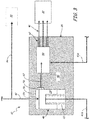
- FIG. 3 shows a schematic of a portion of fuel system 12 in which passive equalization divider valve 28 of the present invention comprises a series-flow, dual-valve system having primary pressurization valve 48 and flow divider valve 50.
- Valves 48 and 50 are integrated into housing 52, which includes inlet 54, piston cylinder 56, window 58, feed 60 and outlets 62.
- Primary pressurization valve 48 includes piston 64 and spring 66.
- Flow divider valve 50 comprises a divider valve of conventional design.
- Primary valve 48 is provided with control pressure through line 40B, which is connected to fuel line 34.
- Flow divider valve 50 is provided with a drain outlet at line 40A.
- fuel flows into inlet 54 of housing 52 from fuel line 42 ( FIG. 1 ).
- the fuel pressure is low so that valve 48 does not open.
- Fuel pressure from line 40B balances static fuel pressure from inlet 54.
- line 40B may be connected to another low pressure point within fuel system 12, such as fuel line 38.
- the spring force of spring 66 biases piston 64 against inlet 62 thereby preventing fuel flow to window 58.
- Fuel continues to flow from line 42 into line 44 and on to primary nozzles 30.
- backpressure builds within line 44 allowing fuel to be atomized at nozzles 30.
- primary valve 48 begins to open due to increased fuel flow rates, which overcomes the force applied by spring 66.
- Piston 64 retreats within piston cylinder 56 to uncover window 58, permitting fuel to leak into feed 60. This occurs within region A in FIG. 2 .
- Divider valve 50 operates in a conventional manner to split the fuel flow into multiple paths at outlets 62 for feeding each secondary nozzle 32 individually or for feeding zones of injectors, such as with a manifold or manifolds.
- the pressure required to open valve 50 is much lower than the pressure required to open valve 48, as provided by spring 66.
- FIG. 4 shows a schematic of a portion of fuel system 12 in which passive equalization divider valve 28 of the present invention comprises a double-action, linear piston valve having piston 68 disposed within housing 70.
- Housing 70 includes inlet 72, piston cylinder 74, window 76, cross-port 78, primary outlet 80, secondary outlets 82, drain line 84 and drain 86.
- Piston 68 includes actuation face 88, equalization port 90, spring pocket 92, drain port 94, balance port 96, spring 98 and orifice 99.
- fuel flows into inlet 72 of housing 70 from fuel line 42 ( FIG. 1 ). Fuel also flows into balance port 96 and into spring pocket 92 to allow static fuel pressure to maintain a force balance on piston 68. The force of the motive flow of fuel, however, acts against piston face 88 to counteract spring force from spring 98 to open valve 28.
- piston 68 moves to uncover window 76 and partially uncover window 90. Window 76 is contoured to maintain a minimum pressure drop and to produce a linear valve position versus fuel flow relationship.
- Fuel flows through window 76, into cross-port 78 and out to primary outlet 80. Thus, fuel is provided to primary nozzles 30 ( FIG. 1 ). Flow above that going to primary nozzles 30 passes thru equalization port 90 to outlets 82 to secondary nozzles 32. The pressure drop across window 90 maintains a backpressure within line 78 such that fuel provided to the primary nozzles through outlet 80 is sufficiently atomized.
- Equalization port 90 is shaped such that, as it continues to open, the pressure drop across it decreases to being negligible compared to the pressure drop produced by window 76. This is low enough to not produce undue burden on pump 24 and the thermal management system of engine 10.
- Housing 70 is also connected to fuel line 40A ( FIG. 1 ) to permit fuel to drain from valve 28 when engine 10 is shut down.
- drain lines 84 are fluidly coupled with secondary outlets 82 to permit fuel to drain back to ecology system 39 through fuel line 40A. Drain lines 84 are fluidly coupled to drain 86 via drain port 94 when piston 68 is fully closed, or all the way to the left with reference to FIG. 4 .
- FIG. 5 shows a schematic of a portion of fuel system 12 in which the passive equalization divider valve 28 of the present invention comprises a double-action, parallel-flow piston valve having piston 100 disposed within housing 102.
- Housing 102 includes inlet 104, barrier 106, screen 108, piston cylinder 110, primary outlet 112, secondary outlet 114, control passage 116, fixed orifice 117, drain valve 118, window 120, control outlet 122 and drain passages 124A, 124B and 124C.
- Piston 100 includes actuation face 126, actuation flange 128, orifice 130, drain window 132, drain window 134 and spring 136.
- Inlet fuel F I contacts barrier 106 and is pushed outward into screen 108 to remove particulates from the fuel flow.
- Inlet fuel F I then engages actuation face 126 and pushes piston 100 to the right (with reference to FIG. 5 ).
- the fuel flow is low so that piston 100 uncovers primary outlet 112, so that most of the fuel can flow out to primary nozzles 30 ( FIG. 1 ).
- a small portion of the fuel flows into line 115 as actuation fuel F A .
- window 137 opens to flow to secondary nozzles 32 via line 114.
- Actuation fuel F A within passage 116 travels to the inside of piston cylinder 110 behind piston 100 and within actuation flange 128. From piston cylinder 110, actuation fuel F A travels through orifice 130 and window 120 and into control outlet 122.
- Window 120 is contoured to provide a smaller restriction with a larger pressure drop at low flow rates (when piston 100 is toward the left in FIG. 5 ) and to provide a larger restriction with a smaller pressure drop at high flow rates (when piston 100 is toward the right in FIG. 5 ).
- Window 137 realizes the total pressure drop in valve 28, including that of orifice 117 plus window 120. This same total pressure drop is realized by primary nozzles 30. Thus, primary nozzles 30 see sufficient pressure at low flows for proper fuel atomization.
- Movement of piston 100 is dictated by the pressure across orifice 117. Initially, the summation of the pressure drops in orifice 117 and window 120 provides a backpressure so that low fuel flow will be forced into primary outlet 112. At low fuel flows, window 120 provides a large pressure drop that limits flow into passage 116. As increased fuel flow continues to stroke piston 100, window 120 opens to increase its restriction size and to reduce backpressure downstream of orifice 117. Thus, more actuation fuel F A is permitted to flow into control passage 116. As piston 100 continues to stroke open, secondary fuel F S increases thru secondary outlet 114, where it is joined by actuation fuel F A for distribution to secondary nozzles 32 ( FIG. 1 ).
- Actuation fuel F A ultimately joins with secondary outlet 114 for distribution to secondary nozzles 32.
- Housing 102 can be provided with a plurality of secondary outlets 114 for distributing fuel to a plurality of secondary nozzles or secondary manifolds. However, only one of the secondary outlets 114 need be provided with control passage 116, fixed orifice 117 and window 120 to control the position of piston 100.
- Housing 102 and piston 100 also include drain lines and windows to permit fuel to drain from valve 28 at shut-down of engine 10. Specifically, drain fuel F D is permitted into the interior of piston 100 through drain line 124A, which engages drain window 132 across the entire stroke length of piston 100. When piston 100 retreats under lack of fuel pressure drain window 132 engages drain line 124C to let fuel drain out to primary nozzles 30. Additionally, with piston 100 retracted, drain valve 118 can be configured to open to allow fuel to leave valve housing 102 at drain line 124B, which connects to fuel line 39 through fuel line 40A ( FIG. 1 ).
Landscapes
- Engineering & Computer Science (AREA)
- Chemical & Material Sciences (AREA)
- Combustion & Propulsion (AREA)
- Mechanical Engineering (AREA)
- General Engineering & Computer Science (AREA)
- Fuel-Injection Apparatus (AREA)
- Output Control And Ontrol Of Special Type Engine (AREA)
Description
- The present invention relates generally to fuel systems for gas turbine engines. More particularly, the present invention relates to systems for delivering fuel to nozzles within combustors of the gas turbine engines.
- Combustors within gas turbine engines are generally of the annular configuration wherein an inner diameter wall circumscribes the engine centerline and an outer diameter wall circumscribes the inner diameter wall to define a combustion chamber therebetween. A ring-like dome typically connects the walls at their upstream end. Fuel nozzles are provided in the dome to inject fuel into a flow of compressed air flowing through the dome. The fuel is injected through small orifices that atomize the fuel to increase combustion efficiency. The nozzles are distributed within the dome evenly around the circumference of the combustor. Recent advancements in combustor design have incorporated the use of primary and secondary fuel nozzles to better control fuel injection during low flow operating states, such as during ignition, ground idle and flight idle. A few primary nozzles that are used during the low-flow conditions are dispersed around the dome and have small injector orifices. A greater number of secondary nozzles having larger orifices are interspersed between the primary nozzles and are brought into use at higher flow conditions, such as during take-off and cruise. The pressure required to properly atomize the fuel in the primary and secondary nozzles can vary widely due to the difference in orifice size.
- The primary nozzles open first when fuel flow is initiated, then the secondary fuel nozzles open as fuel flow increases. The valve maintains a minimum backpressure to the primary nozzles to ensure atomization at low flow conditions. The high atomization pressure required by the primary nozzles therefore requires the valve to have a high opening pressure, thereby introducing a point of high pressure drop at the valve during all operating conditions of the engine when the valve is open. It is, however, undesirable to have such a high pressure drop located within the fuel flow. For example, a high pressure drop within the system increases the working pressure and power of the fuel pump, which introduces heat into the fuel system. The heat is an indication of fuel flow inefficiency and, in any event, must be dealt with or dissipated by the engine fuel management system. There is, therefore, a need for controlling flow to primary and secondary nozzles within gas turbine engine combustors without introducing unnecessary high pressure drops within the system.
US 4 817 389 A describes a fuel injection system.US 5 809 77 A describes an aircraft engine fuel system.US 2010/037612 A1 describes a fuel diverter system for a gas turbine engine.EP 1 965 056 A1 describes a method of starting a gas turbine helicopter engine. - The present invention is directed to a method for providing fuel to primary and secondary fuel nozzles in a gas turbine engine fuel system as claimed in claim 1. The method comprises generating a fuel flow and routing primary fuel from the fuel flow to a primary fuel nozzle. Backpressure on the fuel flow is maintained using a valve. The valve is opened at increased fuel flow to route secondary fuel from the fuel flow to a secondary fuel nozzle. The valve is progressively opened under increasing fuel flows to reduce a pressure drop across the valve produced by the secondary fuel.
- The present invention is directed to a fuel system for dividing fuel between primary and secondary nozzles in a gas turbine engine as claimed in claim 9. The fuel system comprises primary fuel nozzles, secondary fuel nozzles, a fuel pump and a flow divider valve. The primary and secondary fuel nozzles are coupled to a combustor in the gas turbine engine. The fuel pump generates a fuel flow. The flow divider valve receives the fuel flow and divides fuel to the primary and secondary fuel nozzles. The flow divider valve comprises a valve housing having an inlet for receiving the fuel flow, a piston disposed within the housing to maintain a backpressure on the fuel flow, means for providing primary fuel to the primary fuel nozzles, and means for providing secondary fuel to the secondary fuel nozzles while progressively decreasing the pressure drop across the means for providing the secondary fuel to the secondary fuel nozzles.
-
-
FIG. 1 shows a simplified schematic of a gas turbine engine fuel system that provides continuous flow to primary nozzles and equalizing flow to secondary nozzles using a flow divider valve. -
FIG. 2 shows a graph depicting pressure drop in a flow divider valve versus fuel flow for conventional divider valves and passive equalization divider valves of the present invention. -
FIG. 3 shows a schematic of a portion of the fuel system ofFIG. 1 in which the passive equalization divider valve of the present invention comprises a series-flow, dual-valve system. -
FIG. 4 shows a schematic of a portion of the fuel system ofFIG. 1 in which the passive equalization divider valve of the present invention comprises a double-action, linear piston valve. -
FIG. 5 shows a schematic of a portion of the fuel system ofFIG. 1 in which the passive equalization divider valve of the present invention comprises a double-action, parallel-flow piston valve. -
FIG. 1 shows a simplified schematic ofgas turbine engine 10 havingfuel system 12 in which a flow dividing valve system of the present invention is used.Gas turbine engine 10 includescompressor 14,combustor 16,turbine 18 andshaft 20.Fuel system 12 includesfuel tank 22,fuel pump 24, Fuel Metering Unit (FMU) 26 andflow divider valve 28. Combustor 16 includesprimary fuel nozzles 30 andsecondary fuel nozzles 32. - FMU 26 comprises an electronic valve module that regulates fuel flow from
pump 24 based on sensed needs ofengine 10 from, for example, communications with a Full Authority Digital Engine Controller (FADEC) (not shown).Fuel system 12 dispenses fuel fromfuel tank 22 toengine 10. Fuel is drawn intopump 24 throughfuel line 34 and provided to FMU 26 throughfuel line 36. Fuel not needed by FMU 26 is routed back to pump 24 throughreturn line 38. After operation ofengine 10 ceases, any remaining fuel infuel system 12 orcombustor 16 is routed to afuel ecology system 39 viafuel line 40A.Ecology system 39 purges unused fuel fromcombustor 16 anddivider valve 28 to reduce coking and leakage of fuel after shutdown, as is known in the art. FMU 26 is fluidly coupled todivider valve 28 viafuel line 42.Primary nozzles 30 receive fuel directly from FMU 26 throughfuel lines Secondary nozzles 32 receive fuel fromdivider valve 28 throughfuel line 46. Valve 28 can be provided with control pressure throughfuel line 40B that connects into an upstream portion of the fuel system, such asfuel line 34. -
Compressor 14 intakes and compresses a gas, such as atmospheric air, and forces the compressed gas intocombustor 16. Combustor 16 also receives fuel fromfuel pump 24 atprimary nozzles 30 andsecondary nozzles 32. Withincombustor 16, the compressed gas and fuel are mixed and ignited to force expanded gas intoturbine 18.Turbine 18 extracts energy from the expanded gas to cause rotation ofshaft 20 before the gas is expelled fromengine 10 as exhaust. Shaft 20, in turn, powerscompressor 14 and other subsidiary systems. For example, power fromshaft 20 is typically used to turn a tower shaft and gear system for providing input tofuel pump 24 and other accessory systems, such as a generator (not shown). -
Fuel pump 24 operates based on the speed ofshaft 20 and thus provides an unregulated amount of fuel to FMU 26. FMU 26 receives various engine control signals from various sensors, such as pressure and temperature sensors, withinengine 10 to determine various engine needs based on performance demands being placed onengine 10. For example, the amount of fuel needed byengine 10 depends on, among other things, a throttle position actuated by an operator.Engine 10 requires different amounts of fuel under different operating conditions. For example, under start-up conditions, only a low amount of fuel flow is needed byengine 10 as compared to take-off and cruise conditions where a higher amount of fuel flow is required. -
FMU 26 meters flow tocombustor 14.Primary nozzles 16 are directly connected to the flow of metered fuel, as they are required to receive fuel under all operating conditions of the gas turbine engine. In particular, primary nozzles receive fuel under low-flow conditions, such as start-up. In the embodiment shown,fuel line 44 extends directly betweenfuel line 42 andnozzles 30, as is discussed with reference toFIG. 3 .Fuel line 44 may, however, extend fromvalve 28 to connect tonozzles 30, as is discussed with reference toFIGS. 4 and5 .Primary nozzles 30 receive a relatively small fraction of the fuel flow fromline 42. The remainder of the flow passes thruflow divider valve 28 and tosecondary nozzles 32.Flow divider valve 28 is configured to open at a particular backpressure withinline 42 to maintain pressurization for atomizing fuel atprimary nozzles 30 at low-flow conditions.Flow divider valve 28 provides an equalizing flow of fuel tosecondary nozzles 32.Flow divider valve 28 of the present invention allowssecondary nozzles 32 to be passively brought into flow communication withcombustor 16 asgas turbine engine 10 transitions from low-flow operating conditions to high-flow operating conditions, such as during cruise or flight maneuvers.Valve 28 operates based on fuel pressure and flow rate and is not actively controlled. Furthermore, at high fuel flow rates,valve 28 of the present invention operates to reduce the high backpressure it produces at low fuel flow rates to improve efficiency offuel system 12. -
Primary nozzles 30 are configured with small atomization orifices to provide optimal combustion conditions for start-up with a low amount of fuel.Primary nozzles 30 therefore require a large backpressure infuel line 44 to properly operate.Secondary nozzles 32 are configured with larger atomization orifices to permit larger volumes of fuel flow such as at cruise conditions. As such, secondary nozzles do not require as large of backpressure withinfuel line 46.Flow divider valve 28 maintains backpressure withinfuel line 44 at low-flow conditions, but opens under high-flow conditions to increase the size of its flow restriction and reduce the pressure drop it produces. Adequate backpressures are maintained infuel lines -
FIG. 2 shows a graph depicting pressure drop in a flow divider valve versus fuel flow for prior art divider valves and passive equalization divider valves of the present invention. The x-axis indicates fuel flow in a gas turbine engine, indicating zero flow at the y-axis, start or ground/flight idle conditions within zone A, equalization in zone B, and takeoff and cruise within zone C. The y-axis indicates pressure drop, ΔP, across the divider valve, increasing from zero to pressures above what is required to operate a typical flow divider valve. Pressure drop for conventional, non-equalizing divider valves is shown by solid line P0. Pressure drop for the passive equalization divider valves of the present invention is shown by dashed line PE. - During low flow conditions, fuel flow increases until the back pressure in the fuel system (fuel line 44) reaches point D, beyond which point the pressure drop of a conventional divider valve would continue to increase along solid line P0. However, as mentioned, continuously having to overcome the pressure drop produced by the flow divider valve after the primary nozzles have been primed at point D is inefficient. During high flow conditions the static fuel pressure is sufficient such that the need for a restriction with a large pressure drop to maintain backpressure is not needed. For example, the restriction increases the operating burden of
fuel pump 24 and the rest of the thermal management system ofengine 10. - Passive
equalization divider valves 28 of the present invention operate in a two-stage manner to 1) provide adequate backpressure during low-flow conditions to primeprimary nozzles 30, and 2) to reduce the pressure drop signature produced by the divider valve during high-flow conditions when fuel pressure is adequate to maintain pressurization ofprimary nozzles 30, while providing fuel tosecondary nozzles 32. As shown inFIG. 2 , during start-up and ground/flight idle conditions in zone A, the passive equalization divider valves of the present invention permit backpressure inline 44 to build to a particular ΔP at point D, as do conventional divider valves. At point D, passiveequalization divider valve 28 continue to open to permit increasing fuel flow intosecondary nozzles 32. However, rather than merely opening and then continuously being maintained open by fuel flow at the same ΔP, the passive equalization divider valves are configured to reduce the total pressure drop across the valve as the fuel flow rate increases. As shown inFIG. 2 , ΔP drops linearly with respect to fuel flow in zone B. In other embodiments, ΔP may be configured to drop at faster or slower rates at different points of the fuel flow rate (i.e. the fuel flow rate can be non-linear in zone B). At point E, ΔP across passiveequalization divider valve 28 levels off to reduce the workload ofpump 24 under high-flow conditions. -
FIG. 3 shows a schematic of a portion offuel system 12 in which passiveequalization divider valve 28 of the present invention comprises a series-flow, dual-valve system havingprimary pressurization valve 48 and flowdivider valve 50.Valves housing 52, which includesinlet 54,piston cylinder 56,window 58, feed 60 andoutlets 62.Primary pressurization valve 48 includes piston 64 andspring 66.Flow divider valve 50 comprises a divider valve of conventional design.Primary valve 48 is provided with control pressure throughline 40B, which is connected to fuelline 34.Flow divider valve 50 is provided with a drain outlet atline 40A. - During operation of
engine 10, fuel flows intoinlet 54 ofhousing 52 from fuel line 42 (FIG. 1 ). During start-up conditions, the fuel pressure is low so thatvalve 48 does not open. Fuel pressure fromline 40B balances static fuel pressure frominlet 54. In other embodiments,line 40B may be connected to another low pressure point withinfuel system 12, such asfuel line 38. Thus, the spring force ofspring 66 biases piston 64 againstinlet 62 thereby preventing fuel flow towindow 58. Fuel, however, continues to flow fromline 42 intoline 44 and on toprimary nozzles 30. As the start-up ofengine 10 continues, backpressure builds withinline 44 allowing fuel to be atomized atnozzles 30. At a threshold pressure, the magnitude of which is sufficient to atomize the fuel atnozzles 30,primary valve 48 begins to open due to increased fuel flow rates, which overcomes the force applied byspring 66. Piston 64 retreats withinpiston cylinder 56 to uncoverwindow 58, permitting fuel to leak intofeed 60. This occurs within region A inFIG. 2 .Divider valve 50 operates in a conventional manner to split the fuel flow into multiple paths atoutlets 62 for feeding eachsecondary nozzle 32 individually or for feeding zones of injectors, such as with a manifold or manifolds. The pressure required to openvalve 50 is much lower than the pressure required to openvalve 48, as provided byspring 66. As fuel pressure continues to increase asengine 10 moves through equalization (zone B ofFIG. 2 ), piston 64 retreats to fully uncoverwindow 58. At such point the pressure drop produced byprimary valve 48 becomes negligible, leaving only the pressure drop produced by equalizingvalve 50. This occurs at point E inFIG. 2 . As such, overall pressure drop invalve 28 is lowered from that provided byvalve 48 to that provided byvalve 50, thereby lowering the work needed to be done by pump 24 (FIG. 1 ).Divider valve 50 is provided with a drain outlet atline 40A, which is connected to ecology system 39 (FIG. 1 ) to permit unused fuel remaining invalve 50 to be removed from the fuel system. -
FIG. 4 shows a schematic of a portion offuel system 12 in which passiveequalization divider valve 28 of the present invention comprises a double-action, linear pistonvalve having piston 68 disposed withinhousing 70.Housing 70 includesinlet 72,piston cylinder 74,window 76, cross-port 78,primary outlet 80,secondary outlets 82,drain line 84 anddrain 86.Piston 68 includesactuation face 88,equalization port 90,spring pocket 92,drain port 94,balance port 96,spring 98 andorifice 99. - During operation of
engine 10, fuel flows intoinlet 72 ofhousing 70 from fuel line 42 (FIG. 1 ). Fuel also flows intobalance port 96 and intospring pocket 92 to allow static fuel pressure to maintain a force balance onpiston 68. The force of the motive flow of fuel, however, acts againstpiston face 88 to counteract spring force fromspring 98 to openvalve 28. During start-up and ground/flight idle conditions, with low fuel flow,piston 68 moves to uncoverwindow 76 and partially uncoverwindow 90.Window 76 is contoured to maintain a minimum pressure drop and to produce a linear valve position versus fuel flow relationship. Fuel flows throughwindow 76, intocross-port 78 and out toprimary outlet 80. Thus, fuel is provided to primary nozzles 30 (FIG. 1 ). Flow above that going toprimary nozzles 30 passes thruequalization port 90 tooutlets 82 tosecondary nozzles 32. The pressure drop acrosswindow 90 maintains a backpressure withinline 78 such that fuel provided to the primary nozzles throughoutlet 80 is sufficiently atomized. - Under mid to high flow conditions,
piston 68 moves further to the right (with reference toFIG. 4 ), continuing to openequalization port 90.Equalization port 90 is shaped such that, as it continues to open, the pressure drop across it decreases to being negligible compared to the pressure drop produced bywindow 76. This is low enough to not produce undue burden onpump 24 and the thermal management system ofengine 10. -
Housing 70 is also connected to fuelline 40A (FIG. 1 ) to permit fuel to drain fromvalve 28 whenengine 10 is shut down. Specifically,drain lines 84 are fluidly coupled withsecondary outlets 82 to permit fuel to drain back toecology system 39 throughfuel line 40A. Drain lines 84 are fluidly coupled to drain 86 viadrain port 94 whenpiston 68 is fully closed, or all the way to the left with reference toFIG. 4 . -
FIG. 5 shows a schematic of a portion offuel system 12 in which the passiveequalization divider valve 28 of the present invention comprises a double-action, parallel-flow piston valve having piston 100 disposed withinhousing 102.Housing 102 includesinlet 104,barrier 106,screen 108,piston cylinder 110,primary outlet 112,secondary outlet 114, control passage 116, fixedorifice 117,drain valve 118,window 120,control outlet 122 anddrain passages actuation flange 128,orifice 130,drain window 132,drain window 134 andspring 136. - During operation of
engine 10, fuel flows intoinlet 72 ofhousing 70 from fuel line 42 (FIG. 1 ). Inlet fuel FI contacts barrier 106 and is pushed outward intoscreen 108 to remove particulates from the fuel flow. Inlet fuel FI then engages actuation face 126 and pushes piston 100 to the right (with reference toFIG. 5 ). Initially, during start-up conditions, the fuel flow is low so that piston 100 uncoversprimary outlet 112, so that most of the fuel can flow out to primary nozzles 30 (FIG. 1 ). A small portion of the fuel flows into line 115 as actuation fuel FA. At fuel flows above start-up,window 137 opens to flow tosecondary nozzles 32 vialine 114. - Actuation fuel FA within passage 116 travels to the inside of
piston cylinder 110 behind piston 100 and withinactuation flange 128. Frompiston cylinder 110, actuation fuel FA travels throughorifice 130 andwindow 120 and intocontrol outlet 122.Window 120 is contoured to provide a smaller restriction with a larger pressure drop at low flow rates (when piston 100 is toward the left inFIG. 5 ) and to provide a larger restriction with a smaller pressure drop at high flow rates (when piston 100 is toward the right inFIG. 5 ).Window 137 realizes the total pressure drop invalve 28, including that oforifice 117 pluswindow 120. This same total pressure drop is realized byprimary nozzles 30. Thus,primary nozzles 30 see sufficient pressure at low flows for proper fuel atomization. - Movement of piston 100 is dictated by the pressure across
orifice 117. Initially, the summation of the pressure drops inorifice 117 andwindow 120 provides a backpressure so that low fuel flow will be forced intoprimary outlet 112. At low fuel flows,window 120 provides a large pressure drop that limits flow into passage 116. As increased fuel flow continues to stroke piston 100,window 120 opens to increase its restriction size and to reduce backpressure downstream oforifice 117. Thus, more actuation fuel FA is permitted to flow into control passage 116. As piston 100 continues to stroke open, secondary fuel FS increases thrusecondary outlet 114, where it is joined by actuation fuel FA for distribution to secondary nozzles 32 (FIG. 1 ). Actuation fuel FA ultimately joins withsecondary outlet 114 for distribution tosecondary nozzles 32. Housing 102 can be provided with a plurality ofsecondary outlets 114 for distributing fuel to a plurality of secondary nozzles or secondary manifolds. However, only one of thesecondary outlets 114 need be provided with control passage 116, fixedorifice 117 andwindow 120 to control the position of piston 100. -
Housing 102 and piston 100 also include drain lines and windows to permit fuel to drain fromvalve 28 at shut-down ofengine 10. Specifically, drain fuel FD is permitted into the interior of piston 100 throughdrain line 124A, which engagesdrain window 132 across the entire stroke length of piston 100. When piston 100 retreats under lack of fuelpressure drain window 132 engages drain line 124C to let fuel drain out toprimary nozzles 30. Additionally, with piston 100 retracted,drain valve 118 can be configured to open to allow fuel to leavevalve housing 102 atdrain line 124B, which connects to fuelline 39 throughfuel line 40A (FIG. 1 ). - While the invention has been described with reference to an exemplary embodiment(s), it will be understood by those skilled in the art that various changes may be made without departing from the scope of the invention. In addition, many modifications may be made to adapt a particular situation or material to the teachings of the invention without departing from the essential scope thereof. Therefore, it is intended that the invention not be limited to the particular embodiment(s) disclosed, but that the invention will include all embodiments falling within the scope of the appended claims.
Claims (15)
- A method for providing fuel to primary and secondary fuel nozzles in a gas turbine engine fuel system (12), the method comprising:generating a fuel flow at a low flow rate;routing primary fuel from the fuel flow to a primary fuel nozzle (30);maintaining a backpressure on the fuel flow using a passive equalization divider valve (28);wherein maintaining a backpressure on the fuel flow comprises:biasing a spring-loaded piston (64, 100) within a piston chamber of the valve housing (102) against the fuel flow opening the passive equalization divider valve at a high flow rate of the fuel flow to route secondary fuel from the fuel flow to secondary fuel nozzles (32); andprogressively opening the passive equalization divider valve (28) from the low flow rate to the high flow rate to reduce a pressure drop across the first flow divider valve (28) produced by the secondary fuel; and wherein progressively opening the valve from the low flow rate to the high flow rate comprises:
moving the spring-loaded piston against a window in the housing (102) to produce the secondary fuel, and further comprising routing the secondary fuel through a multi-port flow divider valve (50) disposed within the housing. - The method of claim 1 wherein progressively opening the passive equalization divider valve (28) from the low flow rate to the high flow rate to reduce a pressure drop across the valve produced by the secondary fuel further comprises opening the passive equalization divider valve until the pressure drop is negligible.
- The method of claim 1 and further comprising dividing the secondary fuel into a plurality of secondary nozzles, or further comprising:
routing fuel flow to behind the spring-biased piston (64, 100) in the piston chamber to balance static fuel pressure across the piston. - The method of claim 1 wherein routing primary fuel from the fuel flow to a primary fuel nozzle (30) comprises:
displacing the piston (64, 102) past a contoured window (76, 120) in the housing to achicvc a linear relationship between valve position and primary fuel flow. - The method of claim 4 wherein progressively opening the passive equalization divider valve from the low flow rate to the high flow rate comprises:
moving a slot on the piston (28, 48, 100) that is in fluid communication with the primary fuel into fluid communication with a plurality of secondary nozzle outlets in the valve housing. - The method of claim 4, wherein the slot is contoured to permit a first secondary fuel flow rate over a first length of the slot and a second secondary fuel flow rate over a second length of the slot.
- The method of claim 1 wherein:
routing primary fuel from the fuel flow to a primary fuel nozzle (30) comprises displacing the piston past a first window in the housing; and
opening the valve at the high flow rate of the fuel flow to route secondary fuel from the fuel flow to secondary nozzles comprises displacing the piston past a second window in the housing. - The method of claim 1, further comprising:displacing the piston (64, 100) past a third window (132) located between the first (120) and second (137) windows to route equalizing fuel from the fuel flow to behind the piston (100) in the piston chamber;passing the equalizing fuel through a fixed orifice (130) on the piston (100), andpassing the equalizing fuel from the piston chamber through a variable orifice en route to the second window.
- A fuel system for dividing fuel between primary and secondary nozzles in a gas turbine engine, the fuel system comprising:primary (30) and secondary (32) fuel nozzles coupled to a combustor (16) in the gas turbine engine (10);a fuel pump (24) that generates a fuel flow;a passive equalization divider valve (28) that receives the fuel flow and divides fuel to the primary (30) and secondary (32) fuel nozzles, the passive equalization divider valve (28) comprising:a valve housing having an inlet for receiving the fuel flow;a piston (64,100) disposed within the housing (102) to maintain a back pressure on the fuel flow;means for providing primary fuel to the primary fuel nozzles; andmeans for providing secondary fuel to the secondary fuel nozzles while progressively decreasing the pressure drop across the means for providing the secondary fuel to the secondary fuel nozzles, the means for providing secondary fuel to the secondary fuel nozzles comprising a window in the valve housing disposed along the piston to route the secondary fuel through a second fuel line; anda multi-port flow divider valve (50) disposed within the housing and coupled to the secondary fuel line and having a plurality of outlets fluidly coupled to the secondary nozzles
- The fuel system of claim 9 wherein:
the means for providing primary fuel to the primary fuel nozzles comprises:a window in the housing fluidly coupled to a first fluid line extending to the primary nozzles, wherein the window is contoured to achieve a linear relationship between valve (28) position and primary fuel flow; andthe means for providing secondary fuel to the secondary fuel nozzles comprises:
a slot on the piston that is in fluid communication with the first fuel line and a second fuel line in fluid communication with the secondary fuel nozzles, and wherein the slot is contoured to permit a first secondary fuel flow rate over a first length of the slot and a second secondary fuel flow rate over a second length of the slot. - The fuel system of claim 9 wherein:the means for providing primary fuel to the primary fuel nozzles comprises:
a first window (120) in the housing coupled to a first fuel line extending from the valve housing to the primary nozzles; andthe means for providing secondary fuel to the secondary fuel nozzles comprises:
a second window (137) in the housing coupled to a second fuel line extending from the valve housing to the secondary nozzles. - The fuel system of claim 9, wherein the means for providing secondary fuel to the secondary fuel nozzles further comprises:a third window (132) in the housing positioned between the first (120) and second (137) windows, the third (132) window coupled to a third fuel line extending to a cavity behind the spring-actuated piston;a fixed orifice (130) positioned on the piston (100) to receive fuel from the cavity;a fourth fuel line extending from the cavity to the second fuel line; anda variable orifice positioned between the orifice and the fourth fuel line.
- The fuel system of claim 9 and further comprising means for routing fuel flow to a cavity behind the piston.
- The fuel system of claim 9, wherein the means for routing fuel flow to the cavity behind the piston comprises:
a fuel passage extending through the piston, or wherein the means for routing fuel flow to the cavity behind the piston comprises:
a fuel line connecting the fuel flow to the cavity behind the piston. - The fuel system of claim 9 and further comprising:a fuel tank (22) from which the fuel pump (24) receives fuel; anda fuel metering unit (26) disposed between the fuel pump (24) and the passive equalization divider valve (28) to deliver a metered flow of fuel to the passive equalization divider valve and to return unused fuel to a fuel ecology system, and further comprising a drain line (84) for connecting the means for providing secondary fuel to the fuel ecology system.
Applications Claiming Priority (1)
| Application Number | Priority Date | Filing Date | Title |
|---|---|---|---|
| US13/431,187 US8590310B2 (en) | 2012-03-27 | 2012-03-27 | Passive equilization flow divider valve |
Publications (3)
| Publication Number | Publication Date |
|---|---|
| EP2644864A2 EP2644864A2 (en) | 2013-10-02 |
| EP2644864A3 EP2644864A3 (en) | 2016-11-09 |
| EP2644864B1 true EP2644864B1 (en) | 2020-12-30 |
Family
ID=47710006
Family Applications (1)
| Application Number | Title | Priority Date | Filing Date |
|---|---|---|---|
| EP13155199.6A Active EP2644864B1 (en) | 2012-03-27 | 2013-02-14 | Passive equalization flow divider valve |
Country Status (3)
| Country | Link |
|---|---|
| US (1) | US8590310B2 (en) |
| EP (1) | EP2644864B1 (en) |
| CA (1) | CA2806951C (en) |
Families Citing this family (12)
| Publication number | Priority date | Publication date | Assignee | Title |
|---|---|---|---|---|
| US9447733B2 (en) * | 2013-03-14 | 2016-09-20 | Pratt & Whitney Canada Corp. | Gas turbine engine fuel system with ecology valve |
| FR3014488B1 (en) * | 2013-12-05 | 2018-10-19 | Safran Aircraft Engines | VALVE FOR FUEL CIRCUIT OF AN AIRCRAFT ENGINE |
| US20160169120A1 (en) * | 2014-12-10 | 2016-06-16 | United Technologies Corporation | Fuel Schedule for Robust Gas Turbine Engine Transition Between Steady States |
| US20180135531A1 (en) * | 2016-11-15 | 2018-05-17 | General Electric Company | Auto-thermal valve for passively controlling fuel flow to axial fuel stage of gas turbine |
| GB2557603B (en) * | 2016-12-09 | 2020-01-15 | Rolls Royce Plc | Fuel supply system |
| US11536201B2 (en) | 2019-05-15 | 2022-12-27 | Pratt & Whitney Canada Corp. | System and method for purging a fuel manifold of a gas turbine engine through a flow divider valve |
| US11391214B2 (en) | 2019-05-15 | 2022-07-19 | Pratt & Whitney Canada Corp. | System and method for purging a fuel manifold of a gas turbine engine using a flow divider assembly |
| US11486303B2 (en) | 2019-05-15 | 2022-11-01 | Pratt & Whitney Canada Corp. | System and method for purging a fuel manifold of a gas turbine engine using a pump |
| CN111963323B (en) * | 2020-07-29 | 2022-08-02 | 东方电气自动控制工程有限公司 | Fuel control method in gas turbine speed-up process |
| FR3115075B1 (en) * | 2020-10-14 | 2022-10-21 | Safran Aircraft Engines | FUEL SUPPLY CIRCUIT FOR A TURBOMACHINE COMBUSTION CHAMBER |
| US11994076B2 (en) * | 2021-03-31 | 2024-05-28 | Woodward, Inc. | Multi-step pressurizing valve system |
| CN115653759A (en) * | 2022-10-13 | 2023-01-31 | 中国航发四川燃气涡轮研究院 | Afterburner oil supply system based on flow distribution and control flow design method |
Family Cites Families (27)
| Publication number | Priority date | Publication date | Assignee | Title |
|---|---|---|---|---|
| US3032986A (en) * | 1952-11-28 | 1962-05-08 | Chandler Evans Corp | Fuel and speed control system for turbojet engine |
| GB1376746A (en) * | 1971-02-08 | 1974-12-11 | Dowty Fuel Syst Ltd | Fluid flow distribution apparatus |
| US4027473A (en) | 1976-03-05 | 1977-06-07 | United Technologies Corporation | Fuel distribution valve |
| US4817389A (en) * | 1987-09-24 | 1989-04-04 | United Technologies Corporation | Fuel injection system |
| US4949538A (en) | 1988-11-28 | 1990-08-21 | General Electric Company | Combustor gas feed with coordinated proportioning |
| US5321949A (en) | 1991-07-12 | 1994-06-21 | General Electric Company | Staged fuel delivery system with secondary distribution valve |
| US5329759A (en) | 1993-06-30 | 1994-07-19 | Pratt & Whitney Canada, Inc. | Method for regulating fuel flow in a gas turbine engine |
| US5402634A (en) | 1993-10-22 | 1995-04-04 | United Technologies Corporation | Fuel supply system for a staged combustor |
| US5465570A (en) * | 1993-12-22 | 1995-11-14 | United Technologies Corporation | Fuel control system for a staged combustor |
| US5735117A (en) * | 1995-08-18 | 1998-04-07 | Fuel Systems Textron, Inc. | Staged fuel injection system with shuttle valve and fuel injector therefor |
| US5711145A (en) * | 1995-10-10 | 1998-01-27 | Alliedsignal, Inc. | Combined pressurizing, flow measuring and flow splitting valve |
| US5809771A (en) * | 1996-01-19 | 1998-09-22 | Woodward Governor Company | Aircraft engine fuel system |
| US5848525A (en) | 1996-08-30 | 1998-12-15 | General Electric Company | Fuel manifold staging valve |
| US6092546A (en) * | 1997-12-12 | 2000-07-25 | Alliedsignal Inc. | Fuel flow divider and pressurizing valve for gas turbine |
| US6314998B1 (en) * | 1999-07-27 | 2001-11-13 | Alliedsignal Inc. | Fuel divider and ecology system for a gas turbine engine |
| DE60217768T2 (en) | 2001-07-18 | 2007-11-15 | Rolls-Royce Plc | Fuel delivery device |
| US6666015B2 (en) | 2002-01-28 | 2003-12-23 | Hamilton Sundstrand | Simplified fuel control for use with a positive displacement pump |
| US7007452B1 (en) * | 2003-06-13 | 2006-03-07 | Woodward Governor Company | Fuel system for a gas turbine engine |
| GB0329626D0 (en) * | 2003-12-23 | 2004-01-28 | Goodrich Control Sys Ltd | Fuel system |
| FR2913250B1 (en) * | 2007-03-02 | 2009-05-29 | Turbomeca Sa | METHOD FOR STARTING A GAS TURBINE HELICOPTER ENGINE, FUEL SUPPLY CIRCUIT FOR SUCH AN ENGINE, AND MOTOR HAVING SUCH A CIRCUIT |
| GB0708745D0 (en) * | 2007-05-04 | 2007-06-13 | Rolls Royce Plc | Fuel supply system |
| US7836676B2 (en) * | 2007-06-04 | 2010-11-23 | Honeywell International Inc. | Fuel metering valve back-up position control system |
| US8353306B2 (en) * | 2008-08-12 | 2013-01-15 | Honeywell International Inc. | Fuel divider system for gas turbine engine |
| US8820087B2 (en) | 2008-09-08 | 2014-09-02 | Siemens Energy, Inc. | Method and system for controlling fuel to a dual stage nozzle |
| US8046983B2 (en) * | 2008-09-11 | 2011-11-01 | Honeywell International Inc. | Ecology valve fuel return system for gas turbine engine |
| US8122699B2 (en) * | 2008-12-03 | 2012-02-28 | Honeywell International Inc. | Ecology valve fuel return system operable in fluid isolation during gas turbine engine shut-down |
| US8276360B2 (en) * | 2009-05-22 | 2012-10-02 | Hamilton Sundstrand Corporation | Dual-pump fuel system and method for starting a gas turbine engine |
-
2012
- 2012-03-27 US US13/431,187 patent/US8590310B2/en active Active
-
2013
- 2013-02-14 EP EP13155199.6A patent/EP2644864B1/en active Active
- 2013-02-14 CA CA2806951A patent/CA2806951C/en active Active
Non-Patent Citations (1)
| Title |
|---|
| None * |
Also Published As
| Publication number | Publication date |
|---|---|
| EP2644864A3 (en) | 2016-11-09 |
| US20130255270A1 (en) | 2013-10-03 |
| CA2806951A1 (en) | 2013-09-27 |
| EP2644864A2 (en) | 2013-10-02 |
| CA2806951C (en) | 2015-11-17 |
| US8590310B2 (en) | 2013-11-26 |
Similar Documents
| Publication | Publication Date | Title |
|---|---|---|
| EP2644864B1 (en) | Passive equalization flow divider valve | |
| US9500135B2 (en) | Fuel feed circuit for an aeroengine having a high pressure pump system with two pumps | |
| EP3232036B1 (en) | Dual pump fuel system with pump sharing connection | |
| US9222418B2 (en) | Fuel feed circuit with hydraulic actuator and fuel metering unit for an aeroengine | |
| EP2744996B1 (en) | Split control unit | |
| EP2497923B1 (en) | Fuel system | |
| EP3735560B1 (en) | Gas turbine combustor comprising a torch igniter and method of delivering fuel to a torch igniter | |
| US4157012A (en) | Gaseous fuel delivery system | |
| EP2778372B1 (en) | Gas turbine engine fuel system with ecology valve | |
| EP2891768B1 (en) | Engine fuel control system | |
| US9068509B2 (en) | Gas turbine engine fuel control thrust control override system | |
| EP3258083B1 (en) | Fuel windmill bypass with shutoff signal for a gas turbine engine and corresponding method | |
| US20240151183A1 (en) | Systems and methods for purging a fuel manifold of a gas turbine engine | |
| US5187936A (en) | Continuous flow fuel circulation system | |
| US7950232B2 (en) | Fuel feed circuit for an aircraft engine | |
| RU2476702C2 (en) | Gas turbine engine fuel feed system |
Legal Events
| Date | Code | Title | Description |
|---|---|---|---|
| PUAI | Public reference made under article 153(3) epc to a published international application that has entered the european phase |
Free format text: ORIGINAL CODE: 0009012 |
|
| AK | Designated contracting states |
Kind code of ref document: A2 Designated state(s): AL AT BE BG CH CY CZ DE DK EE ES FI FR GB GR HR HU IE IS IT LI LT LU LV MC MK MT NL NO PL PT RO RS SE SI SK SM TR |
|
| AX | Request for extension of the european patent |
Extension state: BA ME |
|
| PUAL | Search report despatched |
Free format text: ORIGINAL CODE: 0009013 |
|
| AK | Designated contracting states |
Kind code of ref document: A3 Designated state(s): AL AT BE BG CH CY CZ DE DK EE ES FI FR GB GR HR HU IE IS IT LI LT LU LV MC MK MT NL NO PL PT RO RS SE SI SK SM TR |
|
| AX | Request for extension of the european patent |
Extension state: BA ME |
|
| RIC1 | Information provided on ipc code assigned before grant |
Ipc: F02C 9/26 20060101ALI20161005BHEP Ipc: F02C 7/232 20060101AFI20161005BHEP |
|
| STAA | Information on the status of an ep patent application or granted ep patent |
Free format text: STATUS: REQUEST FOR EXAMINATION WAS MADE |
|
| 17P | Request for examination filed |
Effective date: 20170508 |
|
| RBV | Designated contracting states (corrected) |
Designated state(s): AL AT BE BG CH CY CZ DE DK EE ES FI FR GB GR HR HU IE IS IT LI LT LU LV MC MK MT NL NO PL PT RO RS SE SI SK SM TR |
|
| STAA | Information on the status of an ep patent application or granted ep patent |
Free format text: STATUS: EXAMINATION IS IN PROGRESS |
|
| 17Q | First examination report despatched |
Effective date: 20181008 |
|
| GRAP | Despatch of communication of intention to grant a patent |
Free format text: ORIGINAL CODE: EPIDOSNIGR1 |
|
| STAA | Information on the status of an ep patent application or granted ep patent |
Free format text: STATUS: GRANT OF PATENT IS INTENDED |
|
| INTG | Intention to grant announced |
Effective date: 20200224 |
|
| RAP1 | Party data changed (applicant data changed or rights of an application transferred) |
Owner name: HAMILTON SUNDSTRAND CORPORATION |
|
| GRAJ | Information related to disapproval of communication of intention to grant by the applicant or resumption of examination proceedings by the epo deleted |
Free format text: ORIGINAL CODE: EPIDOSDIGR1 |
|
| RIN1 | Information on inventor provided before grant (corrected) |
Inventor name: GIBBONS, KEVIN Inventor name: DYER, GERALD P. |
|
| STAA | Information on the status of an ep patent application or granted ep patent |
Free format text: STATUS: EXAMINATION IS IN PROGRESS |
|
| GRAP | Despatch of communication of intention to grant a patent |
Free format text: ORIGINAL CODE: EPIDOSNIGR1 |
|
| STAA | Information on the status of an ep patent application or granted ep patent |
Free format text: STATUS: GRANT OF PATENT IS INTENDED |
|
| INTC | Intention to grant announced (deleted) | ||
| INTG | Intention to grant announced |
Effective date: 20200717 |
|
| GRAS | Grant fee paid |
Free format text: ORIGINAL CODE: EPIDOSNIGR3 |
|
| GRAA | (expected) grant |
Free format text: ORIGINAL CODE: 0009210 |
|
| STAA | Information on the status of an ep patent application or granted ep patent |
Free format text: STATUS: THE PATENT HAS BEEN GRANTED |
|
| AK | Designated contracting states |
Kind code of ref document: B1 Designated state(s): AL AT BE BG CH CY CZ DE DK EE ES FI FR GB GR HR HU IE IS IT LI LT LU LV MC MK MT NL NO PL PT RO RS SE SI SK SM TR |
|
| REG | Reference to a national code |
Ref country code: GB Ref legal event code: FG4D |
|
| REG | Reference to a national code |
Ref country code: AT Ref legal event code: REF Ref document number: 1350145 Country of ref document: AT Kind code of ref document: T Effective date: 20210115 |
|
| REG | Reference to a national code |
Ref country code: DE Ref legal event code: R096 Ref document number: 602013074973 Country of ref document: DE |
|
| REG | Reference to a national code |
Ref country code: IE Ref legal event code: FG4D |
|
| PG25 | Lapsed in a contracting state [announced via postgrant information from national office to epo] |
Ref country code: NO Free format text: LAPSE BECAUSE OF FAILURE TO SUBMIT A TRANSLATION OF THE DESCRIPTION OR TO PAY THE FEE WITHIN THE PRESCRIBED TIME-LIMIT Effective date: 20210330 Ref country code: RS Free format text: LAPSE BECAUSE OF FAILURE TO SUBMIT A TRANSLATION OF THE DESCRIPTION OR TO PAY THE FEE WITHIN THE PRESCRIBED TIME-LIMIT Effective date: 20201230 Ref country code: FI Free format text: LAPSE BECAUSE OF FAILURE TO SUBMIT A TRANSLATION OF THE DESCRIPTION OR TO PAY THE FEE WITHIN THE PRESCRIBED TIME-LIMIT Effective date: 20201230 Ref country code: GR Free format text: LAPSE BECAUSE OF FAILURE TO SUBMIT A TRANSLATION OF THE DESCRIPTION OR TO PAY THE FEE WITHIN THE PRESCRIBED TIME-LIMIT Effective date: 20210331 |
|
| REG | Reference to a national code |
Ref country code: AT Ref legal event code: MK05 Ref document number: 1350145 Country of ref document: AT Kind code of ref document: T Effective date: 20201230 |
|
| PG25 | Lapsed in a contracting state [announced via postgrant information from national office to epo] |
Ref country code: BG Free format text: LAPSE BECAUSE OF FAILURE TO SUBMIT A TRANSLATION OF THE DESCRIPTION OR TO PAY THE FEE WITHIN THE PRESCRIBED TIME-LIMIT Effective date: 20210330 Ref country code: SE Free format text: LAPSE BECAUSE OF FAILURE TO SUBMIT A TRANSLATION OF THE DESCRIPTION OR TO PAY THE FEE WITHIN THE PRESCRIBED TIME-LIMIT Effective date: 20201230 Ref country code: LV Free format text: LAPSE BECAUSE OF FAILURE TO SUBMIT A TRANSLATION OF THE DESCRIPTION OR TO PAY THE FEE WITHIN THE PRESCRIBED TIME-LIMIT Effective date: 20201230 |
|
| REG | Reference to a national code |
Ref country code: NL Ref legal event code: MP Effective date: 20201230 |
|
| PG25 | Lapsed in a contracting state [announced via postgrant information from national office to epo] |
Ref country code: HR Free format text: LAPSE BECAUSE OF FAILURE TO SUBMIT A TRANSLATION OF THE DESCRIPTION OR TO PAY THE FEE WITHIN THE PRESCRIBED TIME-LIMIT Effective date: 20201230 |
|
| REG | Reference to a national code |
Ref country code: LT Ref legal event code: MG9D |
|
| PG25 | Lapsed in a contracting state [announced via postgrant information from national office to epo] |
Ref country code: LT Free format text: LAPSE BECAUSE OF FAILURE TO SUBMIT A TRANSLATION OF THE DESCRIPTION OR TO PAY THE FEE WITHIN THE PRESCRIBED TIME-LIMIT Effective date: 20201230 Ref country code: RO Free format text: LAPSE BECAUSE OF FAILURE TO SUBMIT A TRANSLATION OF THE DESCRIPTION OR TO PAY THE FEE WITHIN THE PRESCRIBED TIME-LIMIT Effective date: 20201230 Ref country code: PT Free format text: LAPSE BECAUSE OF FAILURE TO SUBMIT A TRANSLATION OF THE DESCRIPTION OR TO PAY THE FEE WITHIN THE PRESCRIBED TIME-LIMIT Effective date: 20210430 Ref country code: SK Free format text: LAPSE BECAUSE OF FAILURE TO SUBMIT A TRANSLATION OF THE DESCRIPTION OR TO PAY THE FEE WITHIN THE PRESCRIBED TIME-LIMIT Effective date: 20201230 Ref country code: EE Free format text: LAPSE BECAUSE OF FAILURE TO SUBMIT A TRANSLATION OF THE DESCRIPTION OR TO PAY THE FEE WITHIN THE PRESCRIBED TIME-LIMIT Effective date: 20201230 Ref country code: CZ Free format text: LAPSE BECAUSE OF FAILURE TO SUBMIT A TRANSLATION OF THE DESCRIPTION OR TO PAY THE FEE WITHIN THE PRESCRIBED TIME-LIMIT Effective date: 20201230 Ref country code: NL Free format text: LAPSE BECAUSE OF FAILURE TO SUBMIT A TRANSLATION OF THE DESCRIPTION OR TO PAY THE FEE WITHIN THE PRESCRIBED TIME-LIMIT Effective date: 20201230 |
|
| PG25 | Lapsed in a contracting state [announced via postgrant information from national office to epo] |
Ref country code: PL Free format text: LAPSE BECAUSE OF FAILURE TO SUBMIT A TRANSLATION OF THE DESCRIPTION OR TO PAY THE FEE WITHIN THE PRESCRIBED TIME-LIMIT Effective date: 20201230 Ref country code: AT Free format text: LAPSE BECAUSE OF FAILURE TO SUBMIT A TRANSLATION OF THE DESCRIPTION OR TO PAY THE FEE WITHIN THE PRESCRIBED TIME-LIMIT Effective date: 20201230 |
|
| REG | Reference to a national code |
Ref country code: DE Ref legal event code: R119 Ref document number: 602013074973 Country of ref document: DE |
|
| PG25 | Lapsed in a contracting state [announced via postgrant information from national office to epo] |
Ref country code: IS Free format text: LAPSE BECAUSE OF FAILURE TO SUBMIT A TRANSLATION OF THE DESCRIPTION OR TO PAY THE FEE WITHIN THE PRESCRIBED TIME-LIMIT Effective date: 20210430 Ref country code: MC Free format text: LAPSE BECAUSE OF FAILURE TO SUBMIT A TRANSLATION OF THE DESCRIPTION OR TO PAY THE FEE WITHIN THE PRESCRIBED TIME-LIMIT Effective date: 20201230 |
|
| REG | Reference to a national code |
Ref country code: BE Ref legal event code: MM Effective date: 20210228 |
|
| PG25 | Lapsed in a contracting state [announced via postgrant information from national office to epo] |
Ref country code: LU Free format text: LAPSE BECAUSE OF NON-PAYMENT OF DUE FEES Effective date: 20210214 Ref country code: LI Free format text: LAPSE BECAUSE OF NON-PAYMENT OF DUE FEES Effective date: 20210228 Ref country code: IT Free format text: LAPSE BECAUSE OF FAILURE TO SUBMIT A TRANSLATION OF THE DESCRIPTION OR TO PAY THE FEE WITHIN THE PRESCRIBED TIME-LIMIT Effective date: 20201230 Ref country code: AL Free format text: LAPSE BECAUSE OF FAILURE TO SUBMIT A TRANSLATION OF THE DESCRIPTION OR TO PAY THE FEE WITHIN THE PRESCRIBED TIME-LIMIT Effective date: 20201230 Ref country code: CH Free format text: LAPSE BECAUSE OF NON-PAYMENT OF DUE FEES Effective date: 20210228 |
|
| PLBE | No opposition filed within time limit |
Free format text: ORIGINAL CODE: 0009261 |
|
| STAA | Information on the status of an ep patent application or granted ep patent |
Free format text: STATUS: NO OPPOSITION FILED WITHIN TIME LIMIT |
|
| PG25 | Lapsed in a contracting state [announced via postgrant information from national office to epo] |
Ref country code: ES Free format text: LAPSE BECAUSE OF FAILURE TO SUBMIT A TRANSLATION OF THE DESCRIPTION OR TO PAY THE FEE WITHIN THE PRESCRIBED TIME-LIMIT Effective date: 20201230 Ref country code: DK Free format text: LAPSE BECAUSE OF FAILURE TO SUBMIT A TRANSLATION OF THE DESCRIPTION OR TO PAY THE FEE WITHIN THE PRESCRIBED TIME-LIMIT Effective date: 20201230 |
|
| 26N | No opposition filed |
Effective date: 20211001 |
|
| PG25 | Lapsed in a contracting state [announced via postgrant information from national office to epo] |
Ref country code: DE Free format text: LAPSE BECAUSE OF NON-PAYMENT OF DUE FEES Effective date: 20210901 Ref country code: IE Free format text: LAPSE BECAUSE OF NON-PAYMENT OF DUE FEES Effective date: 20210214 |
|
| PG25 | Lapsed in a contracting state [announced via postgrant information from national office to epo] |
Ref country code: SI Free format text: LAPSE BECAUSE OF FAILURE TO SUBMIT A TRANSLATION OF THE DESCRIPTION OR TO PAY THE FEE WITHIN THE PRESCRIBED TIME-LIMIT Effective date: 20201230 |
|
| PG25 | Lapsed in a contracting state [announced via postgrant information from national office to epo] |
Ref country code: IS Free format text: LAPSE BECAUSE OF FAILURE TO SUBMIT A TRANSLATION OF THE DESCRIPTION OR TO PAY THE FEE WITHIN THE PRESCRIBED TIME-LIMIT Effective date: 20210430 |
|
| PG25 | Lapsed in a contracting state [announced via postgrant information from national office to epo] |
Ref country code: BE Free format text: LAPSE BECAUSE OF NON-PAYMENT OF DUE FEES Effective date: 20210228 |
|
| PGFP | Annual fee paid to national office [announced via postgrant information from national office to epo] |
Ref country code: FR Payment date: 20230119 Year of fee payment: 11 |
|
| PG25 | Lapsed in a contracting state [announced via postgrant information from national office to epo] |
Ref country code: HU Free format text: LAPSE BECAUSE OF FAILURE TO SUBMIT A TRANSLATION OF THE DESCRIPTION OR TO PAY THE FEE WITHIN THE PRESCRIBED TIME-LIMIT; INVALID AB INITIO Effective date: 20130214 |
|
| P01 | Opt-out of the competence of the unified patent court (upc) registered |
Effective date: 20230522 |
|
| PG25 | Lapsed in a contracting state [announced via postgrant information from national office to epo] |
Ref country code: CY Free format text: LAPSE BECAUSE OF FAILURE TO SUBMIT A TRANSLATION OF THE DESCRIPTION OR TO PAY THE FEE WITHIN THE PRESCRIBED TIME-LIMIT Effective date: 20201230 |
|
| PG25 | Lapsed in a contracting state [announced via postgrant information from national office to epo] |
Ref country code: SM Free format text: LAPSE BECAUSE OF FAILURE TO SUBMIT A TRANSLATION OF THE DESCRIPTION OR TO PAY THE FEE WITHIN THE PRESCRIBED TIME-LIMIT Effective date: 20201230 |
|
| PG25 | Lapsed in a contracting state [announced via postgrant information from national office to epo] |
Ref country code: MK Free format text: LAPSE BECAUSE OF FAILURE TO SUBMIT A TRANSLATION OF THE DESCRIPTION OR TO PAY THE FEE WITHIN THE PRESCRIBED TIME-LIMIT Effective date: 20201230 |
|
| PGFP | Annual fee paid to national office [announced via postgrant information from national office to epo] |
Ref country code: GB Payment date: 20240123 Year of fee payment: 12 |