EP2644825A2 - System and method for coupling rotor components - Google Patents
System and method for coupling rotor components Download PDFInfo
- Publication number
- EP2644825A2 EP2644825A2 EP13160884.6A EP13160884A EP2644825A2 EP 2644825 A2 EP2644825 A2 EP 2644825A2 EP 13160884 A EP13160884 A EP 13160884A EP 2644825 A2 EP2644825 A2 EP 2644825A2
- Authority
- EP
- European Patent Office
- Prior art keywords
- rotor
- bushings
- bushing
- rotor assembly
- component
- Prior art date
- Legal status (The legal status is an assumption and is not a legal conclusion. Google has not performed a legal analysis and makes no representation as to the accuracy of the status listed.)
- Granted
Links
Images


Classifications
-
- F—MECHANICAL ENGINEERING; LIGHTING; HEATING; WEAPONS; BLASTING
- F01—MACHINES OR ENGINES IN GENERAL; ENGINE PLANTS IN GENERAL; STEAM ENGINES
- F01D—NON-POSITIVE DISPLACEMENT MACHINES OR ENGINES, e.g. STEAM TURBINES
- F01D5/00—Blades; Blade-carrying members; Heating, heat-insulating, cooling or antivibration means on the blades or the members
- F01D5/02—Blade-carrying members, e.g. rotors
- F01D5/06—Rotors for more than one axial stage, e.g. of drum or multiple disc type; Details thereof, e.g. shafts, shaft connections
- F01D5/066—Connecting means for joining rotor-discs or rotor-elements together, e.g. by a central bolt, by clamps
-
- H—ELECTRICITY
- H02—GENERATION; CONVERSION OR DISTRIBUTION OF ELECTRIC POWER
- H02K—DYNAMO-ELECTRIC MACHINES
- H02K7/00—Arrangements for handling mechanical energy structurally associated with dynamo-electric machines, e.g. structural association with mechanical driving motors or auxiliary dynamo-electric machines
- H02K7/003—Couplings; Details of shafts
-
- F—MECHANICAL ENGINEERING; LIGHTING; HEATING; WEAPONS; BLASTING
- F05—INDEXING SCHEMES RELATING TO ENGINES OR PUMPS IN VARIOUS SUBCLASSES OF CLASSES F01-F04
- F05D—INDEXING SCHEME FOR ASPECTS RELATING TO NON-POSITIVE-DISPLACEMENT MACHINES OR ENGINES, GAS-TURBINES OR JET-PROPULSION PLANTS
- F05D2230/00—Manufacture
- F05D2230/60—Assembly methods
- F05D2230/64—Assembly methods using positioning or alignment devices for aligning or centring, e.g. pins
-
- Y—GENERAL TAGGING OF NEW TECHNOLOGICAL DEVELOPMENTS; GENERAL TAGGING OF CROSS-SECTIONAL TECHNOLOGIES SPANNING OVER SEVERAL SECTIONS OF THE IPC; TECHNICAL SUBJECTS COVERED BY FORMER USPC CROSS-REFERENCE ART COLLECTIONS [XRACs] AND DIGESTS
- Y10—TECHNICAL SUBJECTS COVERED BY FORMER USPC
- Y10T—TECHNICAL SUBJECTS COVERED BY FORMER US CLASSIFICATION
- Y10T29/00—Metal working
- Y10T29/49—Method of mechanical manufacture
- Y10T29/49316—Impeller making
- Y10T29/4932—Turbomachine making
- Y10T29/49321—Assembling individual fluid flow interacting members, e.g., blades, vanes, buckets, on rotary support member
Definitions
- the subject matter disclosed herein relates to couplings for rotating components, more specifically, to couplings for turbomachinery.
- Mechanical energy may be transferred in many ways, including by way of rotating parts, such as a shaft or rotor.
- Rotating parts transfer torque through contact forces with other parts.
- torque transmission may be limited by the surface friction between the two parts and the compression force between the parts.
- Bolts may be used to compress the parts for rotating parts.
- utilizing large bolts to create sufficient compression force can be a challenge.
- the invention resides in a rotor assembly with a first rotor component having a first set of bushing receptacles and a first set of bolt holes arranged about a first rotational axis of the first rotor component.
- the rotor assembly also includes a second rotor component having a second set of bushing receptacles and a second set of bolt holes arranged about a second rotational axis of the second rotor component.
- the rotor assembly includes a first set of bushings disposed in the first and second sets of bushing receptacles in a first installed configuration, wherein the first installed configuration of the first set of bushings is configured to align the first and second rotational axes with one another, and the first installed configuration of the first set of bushings is configured to bear at least a first portion of a torque during rotation of the rotor assembly.
- the rotor assembly also includes a first set of bolts extending through the first and second sets of bolt holes to retain the first rotor, the second rotor, and the first set of bushings in the rotor assembly. retain the first rotor, the second rotor, and the first set of bushings in the rotor assembly.
- the invention resides in a system including a turbomachine with a stator and a rotor assembly.
- the rotor assembly includes a first rotor component with a first set of bushing receptacles arranged about a first rotational axis of the first rotor component and a second rotor component having a second set of bushing receptacles arranged about a second rotational axis of the second rotor component.
- the rotor assembly also includes a first set of bushings disposed in the first and second sets of bushing receptacles in a first installed configuration, wherein the first installed configuration of the first set of bushings is configured to align the first and second rotational axes with one another.
- the invention resides in a method including aligning a first rotational axis of a first rotor component with a second rotational axis of a second rotor component by way of a first set of bushings disposed in first opposing bushing receptacles in the first and second rotor components.
- the first set of bushings and the first opposing bushing receptacles are arranged about the first and second rotational axes.
- the method also includes bearing, in the first set of bushings, at least a first portion of a torque during rotation of a rotor assembly having the first and second rotor components.
- a system and method for coupling rotor components as described herein has a rotor assembly with at least two rotor components (e.g., 2 to 100 rotor components).
- Each rotor component has a set of bushing receptacles and a set of bolt holes arranged about a rotational axis of the rotor component.
- each pair of adjacent rotor components may include axially facing sides, which include bushings disposed in opposite bushing receptacles and bolts extending through opposite bolt holes.
- a set of bushings disposed in the set of bushing receptacles of each rotor component aligns the rotational axes of each component and bears at least a first portion of torque during rotation of the coupled rotor components.
- a set of bolts extend through the sets of bolt holes to retain the rotors and set of bushings in the rotor assembly.
- the set of bushings may have a total shear strength greater than the total shear strength of the set of bolts.
- the set of bushings may have a total shear strength great enough to resist normal operating loads and minor over-torques.
- the set of bushings may bear a substantially greater amount of torque than the bolts (e.g., 10 to 100% of total torque).
- the bushings may have a total shear strength greater than 1400 MPa, although the shear strength may vary from one application to another.
- Each bushing may be solid without any bolt hole, or may include a hole (e.g., bolt hole) to pass a bolt for axially securing the rotor components or to improve compliance between rotor components.
- the set of bushings may be close fit or interference fit into the respective sets of bushing receptacles to align the rotational axes in an installed configuration.
- the disclosed embodiments may employ the bushings in a single pair of adjacent rotor components, the disclosed bushing may be disposed between any number of adjacent rotor components (e.g., 2, 3, 4, 5, 6, 7, 8, 9, 10, or more), wherein a set of bushings is disposed in opposite bushing receptacles in axially facing sides of each pair of adjacent rotor components.
- the rotor assembly may be a part of a turbine, a compressor, a generator, a gas turbine engine, or other turbomachinery.
- Each bushing receptacle may include an undercut fillet.
- a method may include aligning a first rotational axis of a first rotor component with a second rotational axis of a second rotor component by way of a first set of bushings disposed in opposing bushing receptacles of the first and second rotor components arranged about the first and second rotational axes.
- the method may also include bearing a portion of a torque in the first set of bushings during rotation of the rotor assembly.
- the method may include aligning a third rotational axis of a third rotor component with the second rotational axis by way of a second set of bushings disposed in other opposing bushing receptacles arranged about the second and third rotational axes and bearing a second portion of the torque in the second set of bushings during rotation of the rotor assembly. Also, the method may include retaining the rotor assembly with a set of bolts extending through bolt holes in the first, second, and third rotor components.
- FIG. 1 illustrates an embodiment of a rotor assembly 10 coupled together by a torque transfer bushing assembly 11.
- a shaft 12 rotates in a circumferential direction 14
- a plurality of rotor components 16 of the rotor assembly 10 also rotate in the circumferential direction 14, while the bushing assembly 11 bears a substantial portion or all of the torque between adjacent rotor components 16.
- the shaft 12 may be coupled to at least one rotor component 16, and the shaft 12 may extend through one or more rotor components 16 as illustrated in FIG. 1 .
- the shaft 12 transmits torque to the one or more rotor components 16 coupled to the shaft 12, and torque is transferred between adjacent rotor components 16 and/or the shaft 12.
- Rotor components 16 may include turbine blades, compressor blades, armatures, gears, pulleys, propellers, or centrifugal pumps, or combinations thereof.
- the rotor assembly 10 may represent all or part of a turbine, a compressor, a pump, a motor, a generator, or any rotary turbomachine.
- Each rotor component 16 may include at least one set of bushing receptacles 22, at least one set of bolt holes 24, and a rotational axis 26.
- the first rotor component 16, 30 and the second rotor component 16, 40 may represent any pair of adjacent rotor components 16 in various embodiments and are shown for clarity.
- the first rotor component 30 has a first set 32 of bushing receptacles 22, a first set 34 of bolt holes 24, and a first rotational axis 36.
- the second rotor component 40 has a second set 42 of bushing receptacles 22, a second set 44 of bolt holes 24, and a second rotational axis 46.
- some rotor components 16 may include more than one set of bushing receptacles 22.
- the second rotor component 40 may have a third set 48 of bushing receptacles 22 as illustrated in FIG. 1 .
- Each set of bushing receptacles 22 of a rotor component 16 may correspond to and be opposed to another set of bushing receptacles 22 of another adjacent rotor component 16.
- the first set 32 of bushing receptacles 22 axially faces and aligns with the second set 42 of bushing receptacles 22.
- a set of bushings 50 may be disposed in the opposing sets of bushing receptacles 22 to align the rotational axes 26 of the rotor components 16, and bear at least a portion of a torque between the rotor components 16 as the shaft 12 and rotor assembly 10 rotate.
- the set of bushings 50 may interference fit in the bushing receptacles 22 in the installed configuration to couple and align the rotor components 16.
- a first set of bushings 52 may be disposed in the opposing first 32 and second 42 sets of bushing receptacles 22 to align the first 26 and second 36 rotational axes with one another as described below.
- three sets of bushings 50 are disposed in three sets of opposing bushing receptacles 22 in adjacent rotor components 16.
- Bolts 18 may extend through the bolt holes 24 to axially compress, retain, and support the rotor components 16 and bushings 50.
- Each bolt 18 may axially compress the rotor components 16 and bushings 50 between a bolt head 20 and a fastener 74 (e.g., nut).
- the bolts 18 support the shaft 12 to reduce deflection of the rotor assembly 10 due gravity and/or loads on the rotor assembly 10.
- the bushings 50 may have a third set 54 of bolt holes, through which at least some of the set of bolts 18 may pass through in addition to the first 34 and second 44 sets of bolt holes 24.
- each bushing 50 may have a solid body without any bolt hole 54.
- FIG. 2 is a cross-sectional view of an embodiment of the rotor assembly 10 of FIG. 1 , taken along line 2-2, illustrating the torque transfer bushing assembly 11 along a frictional interface between the first rotor component 30 and the second rotor component 40.
- FIG. 2 shows each the set of bushing receptacles 22, 32 arranged at a radial distance 60 about the rotational axis 26, 36.
- the bushing assembly 11 refers to the rotor component 30, the same also applies to each rotor component 16 of the rotor assembly 10.
- each bushing receptacle 32 is centered at the same radial distance 60 from the rotational axis 36.
- the bushing receptacles 32 may be arranged at varying radial distances 60 from the rotational axis.
- the bushing receptacles 32 may be disposed at radial distances 60 within certain run-out tolerances used to align the first rotor component 30 relative to the shaft 12, axis 26, and/or other rotor components 16.
- the bushing receptacles 32 may be any shape, including but not limited to, circular (e.g., counterbore, countersink), arcuate, triangular, or rectangular shapes. Certain embodiments with counterbore bushing receptacles 32 may have a diameter 62 within a receptacle tolerance range.
- the diameter 62 of the bushing receptacles 32 may range from approximately 20 to 110 millimeters, 30 to 80 millimeters, 40 to 65 millimeters, or 45 to 55 millimeters. In some embodiments, the bushing receptacle diameter 62 may range from approximately 1 to 20 percent, 2 to 15 percent, 3 to 10 percent, or 5 to 8 percent of the rotor component diameter 66.
- the corresponding bushings 50, 52 may be substantially the same size and shape as the respective bushing receptacles 22, 32. In some embodiments, the bushings 52 may be slightly larger than the corresponding bushing receptacles 32, resulting in an interference fit when disposed in the installed configuration.
- the bushings 52 may also be made within bushing tolerances to properly fit into the bushing receptacles 32 and align rotor components 16 as discussed below.
- FIG. 2 shows two bushings 52 in an installed configuration in the first rotor component 30 in the top and bottom bushing receptacles 32.
- bushings 52 may be disposed in all of the bushing receptacles 32 in an installed configuration to align the first rotor component 30 with the opposing rotor component 40 and transfer torque between the first rotor component 30 and the second rotor component 40.
- the number of bushing receptacles 32 in a set arranged about the rotational axis 36 may be between approximately 2 to 50, 5 to 30, 7 to 25, or 10 to 20.
- the bushing receptacles 32 may be uniformly shaped, sized, and arranged around the rotational axis 36 of the first rotor component 30 to provide for stable rotation in the circumferential direction 14.
- the set of bolt holes 34 are also arranged at the same radial distance 60 from the rotational axis 36 of the first rotor component 30 as the set of bushing receptacles 32.
- the bolt holes 34 may be any shape including, but not limited to, circular, arcuate, triangular, or rectangular shapes with a defined width or diameter 64.
- the bolt hole diameter 64 may range from approximately 5 to 90 millimeters, 10 to 80 millimeters, 25 to 60 millimeters, or 30 to 45 millimeters.
- the bolt hole diameter 64 may be sized relative to the bushing diameter 62.
- the bolt hole diameter 64 may range from approximately 1 to 75 percent, 5 to 50 percent, 10 to 25 percent, or 10 to 15 percent of the bushing diameter 62.
- the set of bolt holes 34 may be concentric with the bushing receptacles 32. Alternatively, the bolt holes 34 may not be concentric with the bushing receptacles 32. Additionally, the bolt holes 34 may be disposed through the first rotor component 30 outside of the bushing receptacles 32 at the same or different radial distance 60 from the rotational axis 36 as the bushing receptacles 32.
- the number of bolt holes 34 in a set arranged about the rotational axis 36 may also be between approximately 2 to 50, 5 to 30, 7 to 25, or 10 to 20. However, the number of bolt holes 34 may be the same or different from the number of bushing receptacles 32. For example, bolt holes 34 may be disposed in approximately 25, 33, 50, 75 or 100 percent of the bushing receptacles 32. In some embodiments, the bolt holes 34 may be uniformly shaped and arranged around the rotational axis 36 of the first rotor component 30 to provide for stable rotation in the circumferential direction 14. In other words, uniformities in the size and/or arrangement of bushing receptacles 32, bushings 52, and/or bolt holes 34 may help to balance the rotor assembly 10.
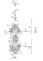
- FIG. 3 illustrates a portion of the rotor assembly 10 of FIG. 1 taken within line 3-3, illustrating an embodiment of the torque transfer bushing assembly 11.
- FIG. 3 shows an exploded cross-sectional view of rotor assembly 10 including the bolt 18, the bushing 50, 52 with the bolt hole 54, the first rotor component 16, 30 with the first bushing receptacle 22, 32 and first bolt hole 34, and the second rotor component 16, 40 with the second bushing receptacle 22, 42.
- the bushing 52 may have bushing diameter 56, while the bushing 52 may have a bolt hole 54 with a diameter 58 that extends through the bushing 52 in the axial direction 70.
- the bolt hole 54 may be approximately concentric with the bushing 52 as illustrated, or the bolt hole 54 may be off center.
- the bushing 52 may be inserted into the first bushing receptacle 32 and the second bushing receptacle 42.
- the bolt 18 may be inserted through the first bolt hole 34 and the second bolt hole 44 and fastened to axially compress and retain the first rotor component 30, the second rotor component 40, and the bushing 52.
- the bolt 18 may also be inserted through the third bolt hole 54 through the bushing 52.
- the bolt 18 may axially compress the rotor assembly 10 in the axial direction 70 via a nut 74 or other fastener at the distal end 76 of the bolt 18 and the bolt head 20.
- torque may be transferred between the first rotor component 30 and the second rotor component 40 by contact forces between the bushing 52 and receptacle faces 78 and/or between the frictional interface 17 of the rotor components 30, 40.
- increased compression from the bolt 18 may increase the torque transmitted by contact forces between rotor components 30, 40 and decrease the torque carried by the bushing 52.
- the bolt hole diameter 64 and/or 58 may be substantially greater than the bolt diameter 80.
- the bolt 18 may have a close tolerance fit in the first bolt hole 34, the second bolt hole 44, and/or the bushing bolt hole 54.
- the bolt 18 may also transmit a portion of the torque between the first rotor component 30 and the second rotor component 40 in the event of over-torques exceeding the flange frictional forces and the bushing elastic strength.
- the bushing diameter 56 is slightly greater than the bushing receptacle diameter 62, thus the bushing 52 may be interference fit in the first bushing receptacle 32 and/or the second bushing receptacle 42.
- the bushing diameter 56 may be approximately 0.5, 1, 2, 3, 4, 5, 10 percent or more greater than the bushing receptacle diameter 52.
- the bushing 52 may transmit torque between the first 30 and second 40 rotor components without an interference fit between the bushing 52 and bushing receptacles 32, 42. In an interference fit, the bushing 52 may be deformed and/or the first 32 and second 42 bushing receptacles 22 may expand to accommodate the interference fit.
- the receptacle walls 82 and bushing 52 may respectively constrain motion in the circumferential direction 14 and/or the radial direction 72.
- the bushing 52 may better transmit torque between the first rotor component 30 and the second rotor component 40 through at least the receptacle walls 82 than without the interference fit.
- the interference fit may also better align the first rotor component 30 with the second rotor component 40 as discussed below.
- the bushing receptacles 32, 42 may have undercut fillets 86 to reduce localized stresses within the receptacles due to the interference fit of the bushing 52, torque transmission by the bushing 52, vibrations, or other forces, or combinations thereof.
- the undercut fillets 86 may be shot peened. A shot peened undercut fillet may help prevent high cycle fatigue of the first 32 and second 42 bushing receptacles 22.
- Concentric alignment of the first rotational axis 36 with the second rotational axis 46 may improve the torque transmission efficiency of the rotor assembly 10 and/or reduce wear on the shaft 12, first rotor component 30, second rotor component 40, bolts 18, or bushings 52, or combinations thereof.
- Concentrically aligned rotor components 30, 40 and aligned rotational axes 36, 46 may help prevent instabilities, vibrations, and/or fatigue in the rotor assembly 10.
- a concentric and aligned rotor assembly 10 may decrease down time due to maintenance and repairs because of reduced wear on the rotor components 16, bolts, 18, and bushings 52.
- first 32 or second 42 bushing receptacles may be repaired or modified by counterboring larger bushing receptacle diameters 62 into the frictional interface 17 and utilizing bushings 52 with larger diameters 56.
- Concentric alignment of the rotor components 30, 40 may depend at least in part on the run-out tolerance of the radial distance 60 of the bushing receptacles 32, 42 from the respective rotational axes 36, 46.
- a master tool having pins in a complementary pattern to the bushing receptacles 22 of a rotor component 16 may be used to determine the run-out of the rotor component 16.
- the master tool may permit sorting of rotor components 16 within the run-out tolerance of the master tool to select rotor components 16 having bushing receptacles 22 at compatible radial distances 60.
- a master tool may be used to determine rotor components 16 with bushing receptacles 22 within the run-out tolerance 60 that may be stacked such that the total run-out of the rotor assembly 10 is minimized.
- the bushing 52 may constrain the motion of the first rotor component 30 and the second rotor components 40 in the circumferential direction 14 and/or the radial direction 72 through contact between the bushing 52 and the receptacle walls 82. In this manner, the bushing 52 may also locate the first rotor component 30 in an aligned position relative to the second rotor component 40, such that the first rotational axis 36 and the second rotational axis 46 are approximately coaxial.
- the first bushing receptacle 32 has a first receptacle axis 71
- the bushing 52 has an axis 59
- the second bushing receptacle 42 has a second receptacle axis 73.
- the first 71 and second 73 receptacle axes may be at a radial distance 60 (within run-out tolerances) of the first 36 and second 46 rotational axes.
- the bushing 52 may have a larger diameter 56 than the bushing receptacle diameters 62, and thus be interference fit into the first 32 and second 42 bushing receptacles in the installed configuration. The interference fit may block relative movement between the first rotor component 30 and second rotor component 40, securing the rotor assembly 10 in the installed configuration.
- the bushing 52 may be configured to align the first 71 and second 73 receptacle axes with the bushing axis 59, and thus align the first 36 and second 46 rotational axes to be approximately coaxial.
- a second set of bushings 50 may concentrically align the rotational axis of a third rotor component 16 with the first rotor component 30 and second rotor component 40 by inserting the second set of bushings 50 in bushing receptacles 48 on the second rotor component 40 and opposing bushing receptacles 22 on the third rotor component 16.
- a first bolt hole axis 75 and a second bolt hole axis 77 may be approximately coaxial with the first receptacle axis 71 and second receptacle axis 73 respectively.
- the bolt holes 34, 44 may be approximately coaxial in the installed configuration.
- first bolt hole 34, second bolt hole 44, and bushing bolt hole 54 may not share a common axis, however the first rotational axis 36 and the second rotational axis 46 are approximately coaxial in the installed configuration.
- a bolt 18 may extend through the first 30 and second 40 rotor components without passing through a bushing 52.
- the bolt 18 may have a smaller diameter 80 than the first 34 and second 44 bolt holes and be configured to have clearance to pass through the rotor assembly 10 to retain and axially compress the rotor assembly 10. In this embodiment, only the bolt head 20 and fastener 74 may contact the first rotor component 30 and second rotor component 40. Such smaller diameter bolts 18 with clearance through the first 34 and second 44 bolt holes may not bear a portion of the torque between the first rotor component 30 and the second rotor component 40.
- the receptacle tolerance 62, bushing tolerance 56, and run-out tolerance 60 may be tighter than tolerances for the bolts 18 and first 34 and second 44 bolt holes, so that the bushings 52 disposed in the first 32 and second 42 bushing receptacles 22 may primarily align the first rotational axis 36 with the second rotational axis 46.
- the bushings 52 may transmit a substantially greater amount (or all) of the torque between the first rotor component 30 and second rotor component 40 than the bolts 18.
- the percentage of torque transmitted by the bushings 52 between the first 30 and second 40 rotor components may be between approximately 1 to 100 percent, 25 to 100 percent, 40 to 90 percent, or 50 to 75 percent, with the remaining percentage of torque, if any, being transmitted by the frictional interface 17 of the first 30 and second 40 rotor components and/or the bolts 18.
- the bushings 52 and frictional interface 17 may transmit all the torque between the first 30 and second 40 rotor components during normal operation and minor over-torque operation.
- the bolts 18 may bear torque during major over-torque operation such as a fault torque event.
- the bushings 52 may transmit approximately 90 percent of the torque, the frictional interface 17 may transmit approximately 5 percent of the torque, and the bolts 18 may transmit approximately 5 percent of the torque.
- the bushings 52 may transmit approximately 75 percent of the torque, the frictional interface 17 may transmit approximately 20 percent of the torque, and the bolts 18 may transmit approximately 5 percent of the torque.
- the bushings 52 and first 32 and second 42 bushing receptacles 22 may align the rotor assembly 10, such that the bolts 18 may primarily axially compress the rotor assembly 10.
- the first rotor component 30 is coaxially aligned with a matching and opposing second rotor component 40 through the bushings 52 and opposing bushing receptacles 32, 42 in series and assembled as the rotor assembly 10 with a stack up tolerance for the alignment based primarily on the run-out tolerance of the bushing receptacles 32, 42, the bushing receptacle tolerance 62, and the bushing tolerance 56.
- a bolt 18 of a ductile metal sized to bear torsion and tension loads may be larger than a bolt 18 of the same metal sized to bear primarily a tension load.
- Bolts 18 may be made of many materials including but not limited to steel (e.g., stainless steel or tool steel) or superalloys (e.g., inconel).
- the bushing 52 may bear a portion of the torque transferred between the first rotor component 30 and the second rotor component 40
- the bushing 52 may be made of a high strength, low wear material such as a cobalt alloy (e.g., MP35N or MP159).
- bushings 52 may be sized to bear a fault torque event (e.g., surge in torque), so that the bolts 18 may be capable of bearing the remaining torque.
- a rotor assembly 10 with bushings 52 bearing at least a first portion of the torque may be cheaper, lighter, and/or easier to maintain than a rotor assembly 10 with bolts 18 bearing all the torque.
- the bushings 52 may have a total shear strength between approximately 1400 to 2000 MPa, 1500 to 1900 MPa, 1600 to 1800 MPa, or 1700 to 1750 MPa.
- the bolts 18 may have a total shear strength between approximately 250 to 1200 MPa, 400 to 1000 MPa, 500 to 750 MPa, or 600 to 700 MPa.
- the first set of bushings 52 may have a first total shear strength that is greater than a second total shear strength of the set of bolts 18.
- FIG. 4 illustrates an exploded view of a rotor assembly 10 of a turbomachine 88 having a shaft 12, rotor components 16, bolts 18, and bushings 50 of the torque transfer bushing assembly 11 as described above.
- the shaft 12 may rotate in a circumferential direction 14 with the rotor components 16.
- the shaft 12 may be integral with, fixedly coupled to, or removably coupled at least one rotor component 16 to transfer torque with the rotor component 16 and the entire rotor assembly 10.
- the turbomachine 88 may have rotor components 90, 92, and 94, such as turbine rotor components, compressor rotor components, electrical generator components, load components, or combinations thereof.
- the turbomachine 88 may have a first turbine rotor 90, a second turbine rotor 92, and a compressor rotor 94. As shown in FIG. 4 , the shaft 12 may be coupled to the first turbine rotor 90, extend through and support the second turbine rotor 92, and also extend through other rotor components 16 (e.g., compressor rotor 94, load coupling).
- the rotor assembly 10 of the turbomachine 88 may have two or more turbine rotors 90 in a turbine rotor assembly, two or more compressor rotors 94 in a compressor rotor assembly, or two or more load couplings in a load coupling rotor assembly, or combinations thereof.
- the turbomachine 88 may also include two or more rotor assemblies 10, each having a torque transfer bushing assembly 11.
- the first and second turbine rotors 90, 92 have opposing bushing receptacles 22 of slightly smaller diameters than the first set of bushings 52.
- the second turbine rotor 92 has an additional set of bushing receptacles 22 on the frictional interface 17 opposite the first turbine rotor 90 that corresponds to bushing receptacles 22 on the compressor rotor 94.
- a second set of bushings 53 may also have slightly larger diameters than the corresponding bushing receptacles 22 of the second turbine rotor 92 and the compressor rotor 94.
- a set of bolts 18 may extend through bolt holes 24, 54 of the rotor components 90, 92, 94 and both sets of bushings 52, 53 to fasten with a set of nuts 74 to axially compress and retain the rotor components 90, 92, 94 and bushings 52, 53 in an installed configuration.
- the first set of bushings 52 is interference fit into opposing bushing receptacles 22 to couple the first and second turbine rotors 90, 92
- the second set of bushings 53 is interference fit into corresponding bushing receptacles 22 to couple the second turbine rotor 92 and the compressor rotor 94.
- the bushings 52, 53 may also concentrically align the rotor components 90, 92, 94 about a common rotational axis 26 in series and transfer torque between the rotor components 90, 92, 94.
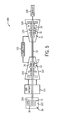
- a turbomachine such as a generator or a gas turbine engine may have at least one stator 124 and one or more rotor assemblies 10 with the torque transfer bushing assembly 11.
- a gas turbine system 100 with the rotor assembly 10 as described above may have a compressor 112 that compresses and directs air from an air intake 114 into a combustor 116.
- the compressor 112 has rotating compressor blades to compress the air.
- the compressed air may combust with fuel to generate hot exhaust gases 118 that are directed through a turbine 120.
- the exhaust gases 118 cause the turbine blades of the turbine 120 to rotate.
- Both the compressor 114 and turbine 120 may have a rotor assembly 10 to transfer torque between the respective rotating rotor components 16 (e.g., turbine or compressor rotors).
- the gas turbine system 100 has a common shaft 12 that couples the rotor assembly 10 of the turbine 120 with the rotor assembly 10 of another component of the gas turbine system 100, such as the compressor 114 or load 122 (e.g., electrical generator).
- the compressor 114, turbine 120, and/or load 122 may have a common rotor assembly 10.
- the stator 124 may not be coupled to the shaft 12, and may include a plurality of non-rotating compressor blades, a plurality of non-rotating turbine blades, a non-rotating armature, or other non-rotating components, or combinations thereof.
- Rotor assemblies 10 as described above may have at least two rotor components 16, a set of bushings 50, a set of opposing bushing receptacles 22, a set of bolt holes 24, and a set of bolts 18.
- a rotor assembly 10 may have between 2 to 25, 3 to 20, 4 to 15, or 5 to 10 rotor components 16 concentrically aligned and coupled by respective sets of bushings 50 in opposing bushing receptacles 22.
- One or more sets of bolts 18 may axially compress, retain, and support all or subsets of rotor components 16.
- a rotor assembly 10 with twelve rotor components 16 may have a first set of bolts 18 extending through all twelve rotor components 16, a second set of bolts 18 extending through the first four rotor components 16, a third set of bolts extending through the first six rotor components 16, and a fourth set of bolts extending through the last four rotor components 16. Additionally, as discussed above, each set of bolts 18 may extend through one or more sets of bushings 50.
- the bushings 50 may be disposed in opposing bushing receptacles 22 that are arranged about the rotational axes 26 of respective rotor components 16.
- the bushing diameter 56 may be slightly larger than the bushing receptacle 22 diameter 62, thus the bushings 50 may be interference fit to align and constrain radial and circumferential movement of the rotor components 16.
- Bolts 18 may extend through the rotor components 16 and/or the bushings 50 to axially compress, retain, and support the rotor components 16 and the bushings 50.
- the bushings 50 may bear a substantially greater portion (or all) of the torque transferred between rotor components 16 than the bolts 18. Because the bolts 18 may bear a small portion, if any, of the torque, the bolts 18 may be sized smaller than if the bolts 18 bore a larger portion of the torque. Additionally, utilizing bushings 50 to align rotor components 16 may permit bolt holes 24 to be made through rotor components 16 that are not coaxial with each other.
Landscapes
- Engineering & Computer Science (AREA)
- Mechanical Engineering (AREA)
- General Engineering & Computer Science (AREA)
- Power Engineering (AREA)
- Turbine Rotor Nozzle Sealing (AREA)
- Structures Of Non-Positive Displacement Pumps (AREA)
- Iron Core Of Rotating Electric Machines (AREA)
- Connection Of Plates (AREA)
Abstract
Description
- The subject matter disclosed herein relates to couplings for rotating components, more specifically, to couplings for turbomachinery.
- Mechanical energy may be transferred in many ways, including by way of rotating parts, such as a shaft or rotor. Rotating parts transfer torque through contact forces with other parts. For friction drive arrangements, torque transmission may be limited by the surface friction between the two parts and the compression force between the parts. Bolts may be used to compress the parts for rotating parts. However, for rotor structures carrying the mass of bolts, utilizing large bolts to create sufficient compression force can be a challenge.
- Certain embodiments commensurate in scope with the originally claimed invention are summarized below. These embodiments are not intended to limit the scope of the claimed invention, but rather these embodiments are intended only to provide a brief summary of possible forms of the invention. Indeed, the invention may encompass a variety of forms that may be similar to or different from the embodiments set forth below.
- In a first aspect, the invention resides in a rotor assembly with a first rotor component having a first set of bushing receptacles and a first set of bolt holes arranged about a first rotational axis of the first rotor component. The rotor assembly also includes a second rotor component having a second set of bushing receptacles and a second set of bolt holes arranged about a second rotational axis of the second rotor component. The rotor assembly includes a first set of bushings disposed in the first and second sets of bushing receptacles in a first installed configuration, wherein the first installed configuration of the first set of bushings is configured to align the first and second rotational axes with one another, and the first installed configuration of the first set of bushings is configured to bear at least a first portion of a torque during rotation of the rotor assembly. The rotor assembly also includes a first set of bolts extending through the first and second sets of bolt holes to retain the first rotor, the second rotor, and the first set of bushings in the rotor assembly. retain the first rotor, the second rotor, and the first set of bushings in the rotor assembly.
- In a second aspect, the invention resides in a system including a turbomachine with a stator and a rotor assembly. The rotor assembly includes a first rotor component with a first set of bushing receptacles arranged about a first rotational axis of the first rotor component and a second rotor component having a second set of bushing receptacles arranged about a second rotational axis of the second rotor component. The rotor assembly also includes a first set of bushings disposed in the first and second sets of bushing receptacles in a first installed configuration, wherein the first installed configuration of the first set of bushings is configured to align the first and second rotational axes with one another.
- In a third aspect, the invention resides in a method including aligning a first rotational axis of a first rotor component with a second rotational axis of a second rotor component by way of a first set of bushings disposed in first opposing bushing receptacles in the first and second rotor components. The first set of bushings and the first opposing bushing receptacles are arranged about the first and second rotational axes. The method also includes bearing, in the first set of bushings, at least a first portion of a torque during rotation of a rotor assembly having the first and second rotor components.
- These and other features, aspects, and advantages of the present invention will become better understood when the following detailed description is read with reference to the accompanying drawings in which like characters represent like parts throughout the drawings, wherein:
-
FIG. 1 is a cross-sectional side view of an embodiment of a rotor assembly with a plurality of rotor components having bolts and bushings; -
FIG. 2 is a cross-sectional view of an embodiment of a rotor component ofFIG. 1 taken within line 2-2; -
FIG. 3 is an exploded cross-sectional view of an embodiment of a bolt, bushing, and bushing receptacles ofFIG. 1 taken within line 3-3; -
FIG. 4 is an exploded view of an embodiment of a rotor assembly; and -
FIG. 5 is a block diagram of a turbine system including an embodiment of a compressor, turbine, and load. - One or more specific embodiments of the present invention will be described below. In an effort to provide a concise description of these embodiments, all features of an actual implementation may not be described in the specification. It should be appreciated that in the development of any such actual implementation, as in any engineering or design project, numerous implementation-specific decisions must be made to achieve the developers' specific goals, such as compliance with system-related and business-related constraints, which may vary from one implementation to another. Moreover, it should be appreciated that such a development effort might be complex and time consuming, but would nevertheless be a routine undertaking of design, fabrication, and manufacture for those of ordinary skill having the benefit of this disclosure.
- When introducing elements of various embodiments of the present invention, the articles "a," "an," "the," and "said" are intended to mean that there are one or more of the elements. The terms "comprising," "including," and "having" are intended to be inclusive and mean that there may be additional elements other than the listed elements.
- A system and method for coupling rotor components as described herein has a rotor assembly with at least two rotor components (e.g., 2 to 100 rotor components). Each rotor component has a set of bushing receptacles and a set of bolt holes arranged about a rotational axis of the rotor component. For example, each pair of adjacent rotor components may include axially facing sides, which include bushings disposed in opposite bushing receptacles and bolts extending through opposite bolt holes. A set of bushings disposed in the set of bushing receptacles of each rotor component aligns the rotational axes of each component and bears at least a first portion of torque during rotation of the coupled rotor components. A set of bolts extend through the sets of bolt holes to retain the rotors and set of bushings in the rotor assembly. The set of bushings may have a total shear strength greater than the total shear strength of the set of bolts. The set of bushings may have a total shear strength great enough to resist normal operating loads and minor over-torques. The set of bushings may bear a substantially greater amount of torque than the bolts (e.g., 10 to 100% of total torque). The bushings may have a total shear strength greater than 1400 MPa, although the shear strength may vary from one application to another. Each bushing may be solid without any bolt hole, or may include a hole (e.g., bolt hole) to pass a bolt for axially securing the rotor components or to improve compliance between rotor components. The set of bushings may be close fit or interference fit into the respective sets of bushing receptacles to align the rotational axes in an installed configuration. Although the disclosed embodiments may employ the bushings in a single pair of adjacent rotor components, the disclosed bushing may be disposed between any number of adjacent rotor components (e.g., 2, 3, 4, 5, 6, 7, 8, 9, 10, or more), wherein a set of bushings is disposed in opposite bushing receptacles in axially facing sides of each pair of adjacent rotor components. In some embodiments, the rotor assembly may be a part of a turbine, a compressor, a generator, a gas turbine engine, or other turbomachinery. Each bushing receptacle may include an undercut fillet.
- Additionally, a method may include aligning a first rotational axis of a first rotor component with a second rotational axis of a second rotor component by way of a first set of bushings disposed in opposing bushing receptacles of the first and second rotor components arranged about the first and second rotational axes. The method may also include bearing a portion of a torque in the first set of bushings during rotation of the rotor assembly. The method may include aligning a third rotational axis of a third rotor component with the second rotational axis by way of a second set of bushings disposed in other opposing bushing receptacles arranged about the second and third rotational axes and bearing a second portion of the torque in the second set of bushings during rotation of the rotor assembly. Also, the method may include retaining the rotor assembly with a set of bolts extending through bolt holes in the first, second, and third rotor components.
- Turning now to the drawings,
FIG. 1 illustrates an embodiment of arotor assembly 10 coupled together by a torquetransfer bushing assembly 11. As ashaft 12 rotates in acircumferential direction 14, a plurality ofrotor components 16 of therotor assembly 10 also rotate in thecircumferential direction 14, while thebushing assembly 11 bears a substantial portion or all of the torque betweenadjacent rotor components 16. Theshaft 12 may be coupled to at least onerotor component 16, and theshaft 12 may extend through one ormore rotor components 16 as illustrated inFIG. 1 . In some embodiments, theshaft 12 transmits torque to the one ormore rotor components 16 coupled to theshaft 12, and torque is transferred betweenadjacent rotor components 16 and/or theshaft 12.Rotor components 16 may include turbine blades, compressor blades, armatures, gears, pulleys, propellers, or centrifugal pumps, or combinations thereof. Thus, therotor assembly 10 may represent all or part of a turbine, a compressor, a pump, a motor, a generator, or any rotary turbomachine. - Four
rotor components 16 are illustrated inFIG. 1 , although more or less are envisioned (e.g., between 2 to 25, 3 to 20, 4 to 15, or 5 to 10 rotor components). Eachrotor component 16 may include at least one set ofbushing receptacles 22, at least one set ofbolt holes 24, and arotational axis 26. Thefirst rotor component second rotor component adjacent rotor components 16 in various embodiments and are shown for clarity. Thefirst rotor component 30 has afirst set 32 ofbushing receptacles 22, afirst set 34 ofbolt holes 24, and a firstrotational axis 36. Thesecond rotor component 40 has asecond set 42 ofbushing receptacles 22, asecond set 44 ofbolt holes 24, and a secondrotational axis 46. In certain embodiments, somerotor components 16 may include more than one set ofbushing receptacles 22. For example, thesecond rotor component 40 may have athird set 48 ofbushing receptacles 22 as illustrated inFIG. 1 . Each set ofbushing receptacles 22 of arotor component 16 may correspond to and be opposed to another set ofbushing receptacles 22 of anotheradjacent rotor component 16. For example, thefirst set 32 ofbushing receptacles 22 axially faces and aligns with thesecond set 42 ofbushing receptacles 22. In an installed configuration, a set ofbushings 50 may be disposed in the opposing sets ofbushing receptacles 22 to align therotational axes 26 of therotor components 16, and bear at least a portion of a torque between therotor components 16 as theshaft 12 androtor assembly 10 rotate. In an embodiment, the set ofbushings 50 may interference fit in thebushing receptacles 22 in the installed configuration to couple and align therotor components 16. For example, a first set ofbushings 52 may be disposed in the opposing first 32 and second 42 sets ofbushing receptacles 22 to align the first 26 and second 36 rotational axes with one another as described below. In the illustrated embodiment, three sets ofbushings 50 are disposed in three sets of opposingbushing receptacles 22 inadjacent rotor components 16. - Bolts 18 (e.g., 1 to 100 or more) may extend through the bolt holes 24 to axially compress, retain, and support the
rotor components 16 andbushings 50. Eachbolt 18 may axially compress therotor components 16 andbushings 50 between abolt head 20 and a fastener 74 (e.g., nut). In some embodiments, thebolts 18 support theshaft 12 to reduce deflection of therotor assembly 10 due gravity and/or loads on therotor assembly 10. In an embodiment, thebushings 50 may have athird set 54 of bolt holes, through which at least some of the set ofbolts 18 may pass through in addition to the first 34 and second 44 sets of bolt holes 24. In another embodiment, eachbushing 50 may have a solid body without anybolt hole 54. -
FIG. 2 is a cross-sectional view of an embodiment of therotor assembly 10 ofFIG. 1 , taken along line 2-2, illustrating the torquetransfer bushing assembly 11 along a frictional interface between thefirst rotor component 30 and thesecond rotor component 40.FIG. 2 shows each the set ofbushing receptacles radial distance 60 about therotational axis bushing assembly 11 refers to therotor component 30, the same also applies to eachrotor component 16 of therotor assembly 10. In an embodiment, eachbushing receptacle 32 is centered at thesame radial distance 60 from therotational axis 36. Alternatively, thebushing receptacles 32 may be arranged at varyingradial distances 60 from the rotational axis. The bushing receptacles 32 may be disposed atradial distances 60 within certain run-out tolerances used to align thefirst rotor component 30 relative to theshaft 12,axis 26, and/orother rotor components 16. The bushing receptacles 32 may be any shape, including but not limited to, circular (e.g., counterbore, countersink), arcuate, triangular, or rectangular shapes. Certain embodiments withcounterbore bushing receptacles 32 may have adiameter 62 within a receptacle tolerance range. Thediameter 62 of thebushing receptacles 32 may range from approximately 20 to 110 millimeters, 30 to 80 millimeters, 40 to 65 millimeters, or 45 to 55 millimeters. In some embodiments, thebushing receptacle diameter 62 may range from approximately 1 to 20 percent, 2 to 15 percent, 3 to 10 percent, or 5 to 8 percent of the rotor component diameter 66. The correspondingbushings respective bushing receptacles bushings 52 may be slightly larger than the correspondingbushing receptacles 32, resulting in an interference fit when disposed in the installed configuration. Thebushings 52 may also be made within bushing tolerances to properly fit into thebushing receptacles 32 and alignrotor components 16 as discussed below.FIG. 2 shows twobushings 52 in an installed configuration in thefirst rotor component 30 in the top andbottom bushing receptacles 32. In an embodiment,bushings 52 may be disposed in all of thebushing receptacles 32 in an installed configuration to align thefirst rotor component 30 with the opposingrotor component 40 and transfer torque between thefirst rotor component 30 and thesecond rotor component 40. The number ofbushing receptacles 32 in a set arranged about therotational axis 36 may be between approximately 2 to 50, 5 to 30, 7 to 25, or 10 to 20. In some embodiments, thebushing receptacles 32 may be uniformly shaped, sized, and arranged around therotational axis 36 of thefirst rotor component 30 to provide for stable rotation in thecircumferential direction 14. - In an embodiment, the set of bolt holes 34 are also arranged at the
same radial distance 60 from therotational axis 36 of thefirst rotor component 30 as the set ofbushing receptacles 32. The bolt holes 34 may be any shape including, but not limited to, circular, arcuate, triangular, or rectangular shapes with a defined width ordiameter 64. In some embodiments, thebolt hole diameter 64 may range from approximately 5 to 90 millimeters, 10 to 80 millimeters, 25 to 60 millimeters, or 30 to 45 millimeters. In some embodiments, thebolt hole diameter 64 may be sized relative to thebushing diameter 62. For example, thebolt hole diameter 64 may range from approximately 1 to 75 percent, 5 to 50 percent, 10 to 25 percent, or 10 to 15 percent of thebushing diameter 62. In the embodiment ofFIG. 2 , the set of bolt holes 34 may be concentric with thebushing receptacles 32. Alternatively, the bolt holes 34 may not be concentric with thebushing receptacles 32. Additionally, the bolt holes 34 may be disposed through thefirst rotor component 30 outside of thebushing receptacles 32 at the same ordifferent radial distance 60 from therotational axis 36 as thebushing receptacles 32. The number of bolt holes 34 in a set arranged about therotational axis 36 may also be between approximately 2 to 50, 5 to 30, 7 to 25, or 10 to 20. However, the number of bolt holes 34 may be the same or different from the number ofbushing receptacles 32. For example, bolt holes 34 may be disposed in approximately 25, 33, 50, 75 or 100 percent of thebushing receptacles 32. In some embodiments, the bolt holes 34 may be uniformly shaped and arranged around therotational axis 36 of thefirst rotor component 30 to provide for stable rotation in thecircumferential direction 14. In other words, uniformities in the size and/or arrangement ofbushing receptacles 32,bushings 52, and/or bolt holes 34 may help to balance therotor assembly 10. -
FIG. 3 illustrates a portion of therotor assembly 10 ofFIG. 1 taken within line 3-3, illustrating an embodiment of the torquetransfer bushing assembly 11.FIG. 3 shows an exploded cross-sectional view ofrotor assembly 10 including thebolt 18, thebushing bolt hole 54, thefirst rotor component first bushing receptacle first bolt hole 34, and thesecond rotor component second bushing receptacle bushing 52 may havebushing diameter 56, while thebushing 52 may have abolt hole 54 with adiameter 58 that extends through thebushing 52 in theaxial direction 70. Thebolt hole 54 may be approximately concentric with thebushing 52 as illustrated, or thebolt hole 54 may be off center. - In an installed configuration, the
bushing 52 may be inserted into thefirst bushing receptacle 32 and thesecond bushing receptacle 42. Thebolt 18 may be inserted through thefirst bolt hole 34 and thesecond bolt hole 44 and fastened to axially compress and retain thefirst rotor component 30, thesecond rotor component 40, and thebushing 52. In certain embodiments, thebolt 18 may also be inserted through thethird bolt hole 54 through thebushing 52. In the installed configuration, thebolt 18 may axially compress therotor assembly 10 in theaxial direction 70 via anut 74 or other fastener at thedistal end 76 of thebolt 18 and thebolt head 20. In an embodiment, torque may be transferred between thefirst rotor component 30 and thesecond rotor component 40 by contact forces between thebushing 52 and receptacle faces 78 and/or between thefrictional interface 17 of therotor components bolt 18 may increase the torque transmitted by contact forces betweenrotor components bushing 52. In some embodiments, thebolt hole diameter 64 and/or 58 may be substantially greater than thebolt diameter 80. In other embodiments, thebolt 18 may have a close tolerance fit in thefirst bolt hole 34, thesecond bolt hole 44, and/or thebushing bolt hole 54. In some embodiments, thebolt 18 may also transmit a portion of the torque between thefirst rotor component 30 and thesecond rotor component 40 in the event of over-torques exceeding the flange frictional forces and the bushing elastic strength. - In some embodiments, the
bushing diameter 56 is slightly greater than thebushing receptacle diameter 62, thus thebushing 52 may be interference fit in thefirst bushing receptacle 32 and/or thesecond bushing receptacle 42. For example, thebushing diameter 56 may be approximately 0.5, 1, 2, 3, 4, 5, 10 percent or more greater than thebushing receptacle diameter 52. However, thebushing 52 may transmit torque between the first 30 and second 40 rotor components without an interference fit between thebushing 52 andbushing receptacles bushing 52 may be deformed and/or the first 32 and second 42bushing receptacles 22 may expand to accommodate the interference fit. In an interference fit, thereceptacle walls 82 andbushing 52 may respectively constrain motion in thecircumferential direction 14 and/or theradial direction 72. Through the interference fit, thebushing 52 may better transmit torque between thefirst rotor component 30 and thesecond rotor component 40 through at least thereceptacle walls 82 than without the interference fit. The interference fit may also better align thefirst rotor component 30 with thesecond rotor component 40 as discussed below. In some embodiments, thebushing receptacles fillets 86 to reduce localized stresses within the receptacles due to the interference fit of thebushing 52, torque transmission by thebushing 52, vibrations, or other forces, or combinations thereof. In an embodiment, the undercutfillets 86 may be shot peened. A shot peened undercut fillet may help prevent high cycle fatigue of the first 32 and second 42bushing receptacles 22. - Concentric alignment of the first
rotational axis 36 with the secondrotational axis 46 may improve the torque transmission efficiency of therotor assembly 10 and/or reduce wear on theshaft 12,first rotor component 30,second rotor component 40,bolts 18, orbushings 52, or combinations thereof. Concentrically alignedrotor components rotational axes rotor assembly 10. Furthermore, a concentric and alignedrotor assembly 10 may decrease down time due to maintenance and repairs because of reduced wear on therotor components 16, bolts, 18, and bushings 52. In some embodiments, first 32 or second 42 bushing receptacles may be repaired or modified by counterboring largerbushing receptacle diameters 62 into thefrictional interface 17 and utilizingbushings 52 withlarger diameters 56. Concentric alignment of therotor components radial distance 60 of thebushing receptacles rotational axes bushing receptacles 22 of arotor component 16 may be used to determine the run-out of therotor component 16. The master tool may permit sorting ofrotor components 16 within the run-out tolerance of the master tool to selectrotor components 16 havingbushing receptacles 22 at compatible radial distances 60. For example, a master tool may be used to determinerotor components 16 withbushing receptacles 22 within the run-outtolerance 60 that may be stacked such that the total run-out of therotor assembly 10 is minimized. - The
bushing 52 may constrain the motion of thefirst rotor component 30 and thesecond rotor components 40 in thecircumferential direction 14 and/or theradial direction 72 through contact between thebushing 52 and thereceptacle walls 82. In this manner, thebushing 52 may also locate thefirst rotor component 30 in an aligned position relative to thesecond rotor component 40, such that the firstrotational axis 36 and the secondrotational axis 46 are approximately coaxial. For example, thefirst bushing receptacle 32 has a first receptacle axis 71, thebushing 52 has anaxis 59, and thesecond bushing receptacle 42 has asecond receptacle axis 73. The first 71 and second 73 receptacle axes may be at a radial distance 60 (within run-out tolerances) of the first 36 and second 46 rotational axes. Thebushing 52 may have alarger diameter 56 than thebushing receptacle diameters 62, and thus be interference fit into the first 32 and second 42 bushing receptacles in the installed configuration. The interference fit may block relative movement between thefirst rotor component 30 andsecond rotor component 40, securing therotor assembly 10 in the installed configuration. Thebushing 52 may be configured to align the first 71 and second 73 receptacle axes with thebushing axis 59, and thus align the first 36 and second 46 rotational axes to be approximately coaxial. In a similar manner, as seen inFIG. 1 , a second set ofbushings 50 may concentrically align the rotational axis of athird rotor component 16 with thefirst rotor component 30 andsecond rotor component 40 by inserting the second set ofbushings 50 inbushing receptacles 48 on thesecond rotor component 40 and opposingbushing receptacles 22 on thethird rotor component 16. - In an embodiment, a first
bolt hole axis 75 and a secondbolt hole axis 77 may be approximately coaxial with the first receptacle axis 71 andsecond receptacle axis 73 respectively. In this embodiment, the bolt holes 34, 44 may be approximately coaxial in the installed configuration. In another embodiment,first bolt hole 34,second bolt hole 44, andbushing bolt hole 54 may not share a common axis, however the firstrotational axis 36 and the secondrotational axis 46 are approximately coaxial in the installed configuration. For example, abolt 18 may extend through the first 30 and second 40 rotor components without passing through abushing 52. In an embodiment without coaxial first 34 and second 44 bolt holes, thebolt 18 may have asmaller diameter 80 than the first 34 and second 44 bolt holes and be configured to have clearance to pass through therotor assembly 10 to retain and axially compress therotor assembly 10. In this embodiment, only thebolt head 20 andfastener 74 may contact thefirst rotor component 30 andsecond rotor component 40. Suchsmaller diameter bolts 18 with clearance through the first 34 and second 44 bolt holes may not bear a portion of the torque between thefirst rotor component 30 and thesecond rotor component 40. - In an embodiment, the
receptacle tolerance 62, bushingtolerance 56, and run-outtolerance 60 may be tighter than tolerances for thebolts 18 and first 34 and second 44 bolt holes, so that thebushings 52 disposed in the first 32 and second 42bushing receptacles 22 may primarily align the firstrotational axis 36 with the secondrotational axis 46. In this embodiment, thebushings 52 may transmit a substantially greater amount (or all) of the torque between thefirst rotor component 30 andsecond rotor component 40 than thebolts 18. In an embodiment, the percentage of torque transmitted by thebushings 52 between the first 30 and second 40 rotor components may be between approximately 1 to 100 percent, 25 to 100 percent, 40 to 90 percent, or 50 to 75 percent, with the remaining percentage of torque, if any, being transmitted by thefrictional interface 17 of the first 30 and second 40 rotor components and/or thebolts 18. Thebushings 52 andfrictional interface 17 may transmit all the torque between the first 30 and second 40 rotor components during normal operation and minor over-torque operation. Thebolts 18 may bear torque during major over-torque operation such as a fault torque event. For example, thebushings 52 may transmit approximately 90 percent of the torque, thefrictional interface 17 may transmit approximately 5 percent of the torque, and thebolts 18 may transmit approximately 5 percent of the torque. As another example, thebushings 52 may transmit approximately 75 percent of the torque, thefrictional interface 17 may transmit approximately 20 percent of the torque, and thebolts 18 may transmit approximately 5 percent of the torque. As discussed above, in some embodiments, thebushings 52 and first 32 and second 42bushing receptacles 22 may align therotor assembly 10, such that thebolts 18 may primarily axially compress therotor assembly 10. In an embodiment, thefirst rotor component 30 is coaxially aligned with a matching and opposingsecond rotor component 40 through thebushings 52 and opposingbushing receptacles rotor assembly 10 with a stack up tolerance for the alignment based primarily on the run-out tolerance of thebushing receptacles bushing receptacle tolerance 62, and thebushing tolerance 56. - A
bolt 18 of a ductile metal sized to bear torsion and tension loads may be larger than abolt 18 of the same metal sized to bear primarily a tension load.Bolts 18 may be made of many materials including but not limited to steel (e.g., stainless steel or tool steel) or superalloys (e.g., inconel). In an embodiment in which thebushing 52 may bear a portion of the torque transferred between thefirst rotor component 30 and thesecond rotor component 40, thebushing 52 may be made of a high strength, low wear material such as a cobalt alloy (e.g., MP35N or MP159). Utilizingbushings 52 to bear at least a first portion of the torque between thefirst rotor component 30 and thesecond rotor component 40 may provide for arotor assembly 10 withsmaller bolts 18. Additionally,bushings 52 may be sized to bear a fault torque event (e.g., surge in torque), so that thebolts 18 may be capable of bearing the remaining torque. Arotor assembly 10 withbushings 52 bearing at least a first portion of the torque may be cheaper, lighter, and/or easier to maintain than arotor assembly 10 withbolts 18 bearing all the torque. For example, thebushings 52 may have a total shear strength between approximately 1400 to 2000 MPa, 1500 to 1900 MPa, 1600 to 1800 MPa, or 1700 to 1750 MPa. Thebolts 18 may have a total shear strength between approximately 250 to 1200 MPa, 400 to 1000 MPa, 500 to 750 MPa, or 600 to 700 MPa. In certain embodiments, the first set ofbushings 52 may have a first total shear strength that is greater than a second total shear strength of the set ofbolts 18. -
FIG. 4 illustrates an exploded view of arotor assembly 10 of a turbomachine 88 having ashaft 12,rotor components 16,bolts 18, andbushings 50 of the torquetransfer bushing assembly 11 as described above. Theshaft 12 may rotate in acircumferential direction 14 with therotor components 16. Theshaft 12 may be integral with, fixedly coupled to, or removably coupled at least onerotor component 16 to transfer torque with therotor component 16 and theentire rotor assembly 10. The turbomachine 88 may haverotor components first turbine rotor 90, asecond turbine rotor 92, and acompressor rotor 94. As shown inFIG. 4 , theshaft 12 may be coupled to thefirst turbine rotor 90, extend through and support thesecond turbine rotor 92, and also extend through other rotor components 16 (e.g.,compressor rotor 94, load coupling). In an embodiment, therotor assembly 10 of the turbomachine 88 may have two ormore turbine rotors 90 in a turbine rotor assembly, two ormore compressor rotors 94 in a compressor rotor assembly, or two or more load couplings in a load coupling rotor assembly, or combinations thereof. The turbomachine 88 may also include two ormore rotor assemblies 10, each having a torquetransfer bushing assembly 11. - As shown in
FIG. 4 , the first andsecond turbine rotors bushing receptacles 22 of slightly smaller diameters than the first set ofbushings 52. Thesecond turbine rotor 92 has an additional set ofbushing receptacles 22 on thefrictional interface 17 opposite thefirst turbine rotor 90 that corresponds to bushingreceptacles 22 on thecompressor rotor 94. A second set ofbushings 53 may also have slightly larger diameters than the correspondingbushing receptacles 22 of thesecond turbine rotor 92 and thecompressor rotor 94. A set ofbolts 18 may extend through bolt holes 24, 54 of therotor components bushings nuts 74 to axially compress and retain therotor components bushings bushings 52 is interference fit into opposingbushing receptacles 22 to couple the first andsecond turbine rotors bushings 53 is interference fit intocorresponding bushing receptacles 22 to couple thesecond turbine rotor 92 and thecompressor rotor 94. Thebushings rotor components rotational axis 26 in series and transfer torque between therotor components - The
rotor assembly 10 described above may be utilized in any system with rotating parts. For example, a turbomachine such as a generator or a gas turbine engine may have at least onestator 124 and one ormore rotor assemblies 10 with the torquetransfer bushing assembly 11. As illustrated inFIG. 5 , agas turbine system 100 with therotor assembly 10 as described above may have acompressor 112 that compresses and directs air from anair intake 114 into acombustor 116. Thecompressor 112 has rotating compressor blades to compress the air. In the combustor, the compressed air may combust with fuel to generate hotexhaust gases 118 that are directed through aturbine 120. Theexhaust gases 118 cause the turbine blades of theturbine 120 to rotate. Both thecompressor 114 andturbine 120 may have arotor assembly 10 to transfer torque between the respective rotating rotor components 16 (e.g., turbine or compressor rotors). In some embodiments, thegas turbine system 100 has acommon shaft 12 that couples therotor assembly 10 of theturbine 120 with therotor assembly 10 of another component of thegas turbine system 100, such as thecompressor 114 or load 122 (e.g., electrical generator). In an embodiment, thecompressor 114,turbine 120, and/or load 122 may have acommon rotor assembly 10. Thestator 124 may not be coupled to theshaft 12, and may include a plurality of non-rotating compressor blades, a plurality of non-rotating turbine blades, a non-rotating armature, or other non-rotating components, or combinations thereof. -
Rotor assemblies 10 as described above may have at least tworotor components 16, a set ofbushings 50, a set of opposingbushing receptacles 22, a set of bolt holes 24, and a set ofbolts 18. In some embodiments, arotor assembly 10 may have between 2 to 25, 3 to 20, 4 to 15, or 5 to 10rotor components 16 concentrically aligned and coupled by respective sets ofbushings 50 in opposingbushing receptacles 22. One or more sets ofbolts 18 may axially compress, retain, and support all or subsets ofrotor components 16. For example, arotor assembly 10 with twelverotor components 16 may have a first set ofbolts 18 extending through all twelverotor components 16, a second set ofbolts 18 extending through the first fourrotor components 16, a third set of bolts extending through the first sixrotor components 16, and a fourth set of bolts extending through the last fourrotor components 16. Additionally, as discussed above, each set ofbolts 18 may extend through one or more sets ofbushings 50. - Technical effects of the disclosed embodiments include aligning and transmitting torque between at least two
rotor components 16 withbushings 50. Thebushings 50 may be disposed in opposingbushing receptacles 22 that are arranged about therotational axes 26 ofrespective rotor components 16. Thebushing diameter 56 may be slightly larger than thebushing receptacle 22diameter 62, thus thebushings 50 may be interference fit to align and constrain radial and circumferential movement of therotor components 16.Bolts 18 may extend through therotor components 16 and/or thebushings 50 to axially compress, retain, and support therotor components 16 and thebushings 50. Thebushings 50 may bear a substantially greater portion (or all) of the torque transferred betweenrotor components 16 than thebolts 18. Because thebolts 18 may bear a small portion, if any, of the torque, thebolts 18 may be sized smaller than if thebolts 18 bore a larger portion of the torque. Additionally, utilizingbushings 50 to alignrotor components 16 may permit bolt holes 24 to be made throughrotor components 16 that are not coaxial with each other. - This written description uses examples to disclose the invention, including the best mode, and also to enable any person skilled in the art to practice the invention, including making and using any devices or systems and performing any incorporated methods. The patentable scope of the invention is defined by the claims, and may include other examples that occur to those skilled in the art. Such other examples are intended to be within the scope of the claims if they have structural elements that do not differ from the literal language of the claims, or if they include equivalent structural elements with insubstantial differences from the literal language of the claims.
- Various aspects and embodiments of the present invention are defined by the following numbered clauses:
- 1. A system, comprising:
- a turbomachine, comprising:
- a stator; and
- a rotor assembly, comprising:
- a first rotor component having a first set of bushing receptacles arranged about a first rotational axis of the first rotor component;
- a second rotor component having a second set of bushing receptacles arranged about a second rotational axis of the second rotor component;
- a first set of bushings disposed in the first and second sets of bushing receptacles in a first installed configuration, wherein the first installed configuration of the first set of bushings is configured to align the first and second rotational axes with one another.
- a turbomachine, comprising:
- 2. The system of any preceding clause wherein the first installed configuration of the first set of bushings is configured to bear at least a first portion of a torque during rotation of the rotor assembly.
- 3. The system of any preceding clause wherein the turbomachine comprises a turbine, a compressor, or a combination thereof.
- 4. The system of any preceding clause, wherein the first set of bushings is interference fit in the first and second sets of bushing receptacles in the first installed configuration.
- 5. The system of any preceding clause wherein each bushing receptacle of the first and second sets of bushing receptacles comprises an undercut fillet.
- 6. A method, comprising:
- aligning a first rotational axis of a first rotor component with a second rotational axis of a second rotor component with a first set of bushings disposed in first opposing bushing receptacles in the first and second rotor components, wherein the first set of bushings and the first opposing bushing receptacles are arranged about the first and second rotational axes; and
- bearing, in the first set of bushings, at least a first portion of a torque during rotation of a rotor assembly having the first and second rotor components.
- 7. The method of any preceding clause comprising:
- aligning a third rotational axis of a third rotor component with the second rotational axis of the second rotor component with a second set of bushings disposed in second opposing bushing receptacles in the second and third rotor components, wherein the second set of bushings and the second opposing bushing receptacles are arranged about the first, second, and third rotational axes; and
- bearing, in the second set of bushings, at least a second portion of the torque during rotation of the rotor assembly having the first, second, and third rotor components.
- 8. The method of any preceding clause comprising retaining the rotor assembly with a first set of bolts extending through bolt holes in the first and second rotor components.
- 9. The method of any preceding clause comprising sorting a plurality of rotor components with a master tool to select the first rotor component and the second rotor component from the plurality of rotor components.
Claims (16)
- A rotor assembly (10), comprising:a first rotor component (16,30) having a first set (32) of bushing receptacles (22) and a first set (34) of bolt holes (24) arranged about a first rotational axis (26) of the first rotor component (16,30);a second rotor component (16,40) having a second set (42) of bushing receptacles (22) and a second set (44) of bolt holes (24) arranged about a second rotational axis (46) of the second rotor component (16,40);a first set of bushings (52) disposed in the first (32) and second sets (42) of bushing receptacles (22) in a first installed configuration, wherein the first installed configuration of the first set of bushings (52) is configured to align the first and second rotational axes (26,40) with one another, and the first installed configuration of the first set of bushings (52) is configured to bear at least a first portion of a torque during rotation of the rotor assembly (10); anda first set of bolts (18) extending through the first and second sets (34,44) of bolt holes (24) to retain the first rotor component (16,30), the second rotor component (16,40), and the first set of bushings (52) in the rotor assembly (10).
- The rotor assembly of claim 1, wherein the first set of bushings (52) has a first total shear strength sufficient to bear normal operating loads and minor over-torque loads.
- The rotor assembly of claim 1 or 2, wherein each bushing (52) in the first set of bushings has a shear strength of greater than or equal to approximately 1400 MPa.
- The rotor assembly of any of claims 1 to 3, wherein the first set of bushings (52) is configured to bear a substantially greater amount of the torque than the first set of bolts (18).
- The rotor assembly of any of any preceding claim, wherein the first set of bushings (52) comprises a third set (54) of bolt holes (24), and the first set of bolts (18) extends through the first (24), second (44), and third sets (54) of bolt holes (24).
- The rotor assembly of any preceding claim, wherein each bushing (50) in the first set of bushings (52) comprises a solid body without any bolt hole (24).
- The rotor assembly of any preceding claim, wherein the first set of bushings (52) is interference fit in the first (32) and second sets (42) of bushing receptacles (22) in the first installed configuration.
- The rotor assembly of any preceding claim, wherein the rotor assembly comprises:a third set (48) of bushing receptacles (22) within the second rotor component;a third rotor component having a fourth set of bushing receptacles and a fourth set of bolt holes arranged about a third rotational axis of the third rotor component;a second set of bushings disposed in the third and fourth sets of bushing receptacles in a second installed configuration, wherein the second installed configuration of the second set of bushings is configured to align the second and third rotational axes with one another, and the second installed configuration of the second set of bushings is configured to bear at least a second portion of the torque during rotation of the rotor assembly; andwherein the first set of bolts extends through the first, second, and fourth sets of bolt holes to retain the first rotor component, the second rotor component, the third rotor component, the first set of bushings, and the second set of bushings in the rotor assembly.
- The rotor assembly of any preceding claim, wherein each bushing receptacle (22) of the first (32) and second sets (42) of bushing receptacles (22) comprises an undercut fillet (86).
- A turbine or a compressor having the rotor assembly (10) of any of claims 1 to 9.
- A generator having the rotor assembly (10) of any of claims 1 to 9.
- A gas turbine engine having the rotor assembly (10) of any of claims 1 to 9.
- A system, comprising:a turbomachine, comprising:a stator; andthe rotor assembly (10) of any of claims 1 to 9.
- A method, comprising:aligning a first rotational axis (26) of a first rotor component (16,30) with a second rotational axis (46) of a second rotor component (16,40) with a first set of bushings (52) disposed in first (32,42) opposing bushing receptacles (22) in the first (16,30) and second rotor (16,40) components, wherein the first set of bushings (52) and the first opposing bushing receptacles (22) are arranged about the first and second rotational axes (26,46); andbearing, in the first set of bushings (52), at least a first portion of a torque during rotation of a rotor assembly (10) having the first and second rotor components (16,30,40).
- The method of claim 14, comprising:aligning a third rotational axis of a third rotor component (16) with the second rotational axis (46) of the second rotor component (16,40) with a second set of bushings (52) disposed in second (42) opposing bushing receptacles (22) in the second and third rotor (16,40) components, wherein the second set of bushings (52) and the second (42) opposing bushing receptacles (22) are arranged about the first, second, and third rotational axes (26,46); andbearing, in the second set of bushings (52), at least a second portion of the torque during rotation of the rotor assembly (10) having the first, second, and third rotor components (16,30,40).
- The method of claim 14 or 15, comprising retaining the rotor assembly (10) with a first set of bolts (18) extending through bolt holes (24) in the first and second rotor components (16,30,40).
Applications Claiming Priority (1)
| Application Number | Priority Date | Filing Date | Title |
|---|---|---|---|
| US13/436,814 US9163514B2 (en) | 2012-03-30 | 2012-03-30 | System and method for coupling rotor components |
Publications (3)
| Publication Number | Publication Date |
|---|---|
| EP2644825A2 true EP2644825A2 (en) | 2013-10-02 |
| EP2644825A3 EP2644825A3 (en) | 2014-08-13 |
| EP2644825B1 EP2644825B1 (en) | 2022-07-20 |
Family
ID=48013782
Family Applications (1)
| Application Number | Title | Priority Date | Filing Date |
|---|---|---|---|
| EP13160884.6A Active EP2644825B1 (en) | 2012-03-30 | 2013-03-25 | Rotor assembly and method for aligning rotor components |
Country Status (5)
| Country | Link |
|---|---|
| US (1) | US9163514B2 (en) |
| EP (1) | EP2644825B1 (en) |
| JP (1) | JP6329337B2 (en) |
| CN (1) | CN103362964A (en) |
| RU (1) | RU2013113937A (en) |
Cited By (1)
| Publication number | Priority date | Publication date | Assignee | Title |
|---|---|---|---|---|
| EP2913484A3 (en) * | 2014-02-26 | 2015-11-25 | Kabushiki Kaisha Toshiba | Power generator and turbine coupling method |
Families Citing this family (4)
| Publication number | Priority date | Publication date | Assignee | Title |
|---|---|---|---|---|
| CN107060904B (en) * | 2017-05-05 | 2023-07-07 | 大唐东北电力试验研究所有限公司 | Double-rotor interchange precision guaranteeing system for high back pressure transformation of steam turbine |
| CN109113795A (en) * | 2018-10-23 | 2019-01-01 | 中国船舶重工集团公司第七0三研究所 | A kind of helium turbine rotor leaf dish |
| CN112682104B (en) * | 2020-12-25 | 2022-11-18 | 福建福清核电有限公司 | Bolt installation method for steam turbine coupling in nuclear power plant |
| CN119664809A (en) * | 2025-02-18 | 2025-03-21 | 杭州默鑫智能科技有限公司 | A coupling used in transmission of sorting machine |
Family Cites Families (13)
| Publication number | Priority date | Publication date | Assignee | Title |
|---|---|---|---|---|
| GB599809A (en) * | 1945-01-15 | 1948-03-22 | Bristol Aeroplane Co Ltd | Improvements in axial flow compressors, turbines and the like |
| SE390834B (en) * | 1975-02-21 | 1977-01-24 | Stal Laval Turbin Ab | ROTOR FOR TURBO MACHINE |
| CH595011A5 (en) * | 1975-06-19 | 1978-01-31 | Bbc Brown Boveri & Cie | |
| SE395174B (en) * | 1975-08-19 | 1977-08-01 | Stal Laval Turbin Ab | PROCEDURE FOR INSTALLING A TURBO MACHINE AND TOOLS FOR PERFORMING THE PROCEDURE |
| FR2329882A1 (en) | 1975-10-28 | 1977-05-27 | Europ Turb Vapeur | Rotor disc tie rod centring ferrule - has recess for short location ring screwed to ferrule on large dia. rod section |
| JPS57210103A (en) * | 1981-06-17 | 1982-12-23 | Hitachi Ltd | Stacked rotor |
| JPS5830405A (en) * | 1981-08-19 | 1983-02-22 | Hitachi Ltd | Rotor mounting device for axial flow machines |
| US5031400A (en) * | 1988-12-09 | 1991-07-16 | Allied-Signal Inc. | High temperature turbine engine structure |
| US6158102A (en) * | 1999-03-24 | 2000-12-12 | General Electric Co. | Apparatus and methods for aligning holes through wheels and spacers and stacking the wheels and spacers to form a turbine rotor |
| US6572337B1 (en) * | 1999-11-30 | 2003-06-03 | General Electric Co. | Turbine rotor torque transmission |
| JP2003120209A (en) * | 2001-10-10 | 2003-04-23 | Mitsubishi Heavy Ind Ltd | Spindle bolt seal structure and gas turbine |
| US6996914B1 (en) * | 2004-08-09 | 2006-02-14 | Project Consulting Services, Inc. | Method and apparatus for best fitting two or more items |
| DE102009013348A1 (en) * | 2009-03-16 | 2010-09-23 | Man Turbo Ag | Device and method for connecting a blade to a rotor shaft of a turbomachine |
-
2012
- 2012-03-30 US US13/436,814 patent/US9163514B2/en active Active
-
2013
- 2013-03-25 EP EP13160884.6A patent/EP2644825B1/en active Active
- 2013-03-28 RU RU2013113937/06A patent/RU2013113937A/en not_active Application Discontinuation
- 2013-03-28 JP JP2013067725A patent/JP6329337B2/en active Active
- 2013-03-28 CN CN2013101035291A patent/CN103362964A/en active Pending
Non-Patent Citations (1)
| Title |
|---|
| None * |
Cited By (1)
| Publication number | Priority date | Publication date | Assignee | Title |
|---|---|---|---|---|
| EP2913484A3 (en) * | 2014-02-26 | 2015-11-25 | Kabushiki Kaisha Toshiba | Power generator and turbine coupling method |
Also Published As
| Publication number | Publication date |
|---|---|
| EP2644825A3 (en) | 2014-08-13 |
| US20130259678A1 (en) | 2013-10-03 |
| JP2013215088A (en) | 2013-10-17 |
| EP2644825B1 (en) | 2022-07-20 |
| JP6329337B2 (en) | 2018-05-23 |
| CN103362964A (en) | 2013-10-23 |
| RU2013113937A (en) | 2014-10-10 |
| US9163514B2 (en) | 2015-10-20 |
Similar Documents
| Publication | Publication Date | Title |
|---|---|---|
| US9297258B2 (en) | Trapped spring balance weight and rotor assembly | |
| EP2644825B1 (en) | Rotor assembly and method for aligning rotor components | |
| EP3112588B1 (en) | Rotor damper | |
| EP2443317B1 (en) | Turbine rotor and balancing method | |
| EP2613000B1 (en) | System for axial retention of rotating segments of a turbine and corresponding method | |
| US9388697B2 (en) | First stage compressor disk configured for balancing the compressor rotor assembly | |
| US8267649B2 (en) | Coupling for rotary components | |
| GB2541263A (en) | Improved alignment of flanged components | |
| CN105308265B (en) | Including be arranged on be shell between axis and rotor combustion gas turbine system shaft device | |
| EP2841715A1 (en) | Apparatus and method for assembling a damper bearing assembly | |
| US20160265370A1 (en) | Chocking and retaining device | |
| EP3081750A1 (en) | Damper ring for a rotor stage | |
| JP6826791B2 (en) | Bearing assembly | |
| US20180216466A1 (en) | Methods and systems for rotating component balancing | |
| EP2354457A2 (en) | Rotor disk and blade | |
| CN104285035B (en) | Turbine Rotor Assembly and Balancing Weights for Turbine Rotor | |
| EP2636845A2 (en) | Compressor/turbine rotor-torque transmission through hybrid drive | |
| EP3208419A1 (en) | Connection of rotatable parts of a gas turbine engine | |
| EP2554790B1 (en) | Self Locking Nut and Bolt Assembly | |
| KR102141626B1 (en) | Turbine apparatus | |
| EP3460196B1 (en) | Bearing assembly for a variable stator vane | |
| GB2546481A (en) | Rotor stage |
Legal Events
| Date | Code | Title | Description |
|---|---|---|---|
| PUAI | Public reference made under article 153(3) epc to a published international application that has entered the european phase |
Free format text: ORIGINAL CODE: 0009012 |
|
| AK | Designated contracting states |
Kind code of ref document: A2 Designated state(s): AL AT BE BG CH CY CZ DE DK EE ES FI FR GB GR HR HU IE IS IT LI LT LU LV MC MK MT NL NO PL PT RO RS SE SI SK SM TR |
|
| AX | Request for extension of the european patent |
Extension state: BA ME |
|
| PUAL | Search report despatched |
Free format text: ORIGINAL CODE: 0009013 |
|
| AK | Designated contracting states |
Kind code of ref document: A3 Designated state(s): AL AT BE BG CH CY CZ DE DK EE ES FI FR GB GR HR HU IE IS IT LI LT LU LV MC MK MT NL NO PL PT RO RS SE SI SK SM TR |
|
| AX | Request for extension of the european patent |
Extension state: BA ME |
|
| RIC1 | Information provided on ipc code assigned before grant |
Ipc: F01D 5/06 20060101AFI20140708BHEP Ipc: H02K 7/00 20060101ALI20140708BHEP |
|
| 17P | Request for examination filed |
Effective date: 20150213 |
|
| RBV | Designated contracting states (corrected) |
Designated state(s): AL AT BE BG CH CY CZ DE DK EE ES FI FR GB GR HR HU IE IS IT LI LT LU LV MC MK MT NL NO PL PT RO RS SE SI SK SM TR |
|
| STAA | Information on the status of an ep patent application or granted ep patent |
Free format text: STATUS: EXAMINATION IS IN PROGRESS |
|
| 17Q | First examination report despatched |
Effective date: 20190531 |
|
| GRAP | Despatch of communication of intention to grant a patent |
Free format text: ORIGINAL CODE: EPIDOSNIGR1 |
|
| STAA | Information on the status of an ep patent application or granted ep patent |
Free format text: STATUS: GRANT OF PATENT IS INTENDED |
|
| INTG | Intention to grant announced |
Effective date: 20220221 |
|
| GRAS | Grant fee paid |
Free format text: ORIGINAL CODE: EPIDOSNIGR3 |
|
| GRAA | (expected) grant |
Free format text: ORIGINAL CODE: 0009210 |
|
| STAA | Information on the status of an ep patent application or granted ep patent |
Free format text: STATUS: THE PATENT HAS BEEN GRANTED |
|
| AK | Designated contracting states |
Kind code of ref document: B1 Designated state(s): AL AT BE BG CH CY CZ DE DK EE ES FI FR GB GR HR HU IE IS IT LI LT LU LV MC MK MT NL NO PL PT RO RS SE SI SK SM TR |
|
| REG | Reference to a national code |
Ref country code: GB Ref legal event code: FG4D |
|
| REG | Reference to a national code |
Ref country code: CH Ref legal event code: EP |
|
| REG | Reference to a national code |
Ref country code: DE Ref legal event code: R096 Ref document number: 602013082091 Country of ref document: DE |
|
| REG | Reference to a national code |
Ref country code: AT Ref legal event code: REF Ref document number: 1505633 Country of ref document: AT Kind code of ref document: T Effective date: 20220815 |
|
| REG | Reference to a national code |
Ref country code: IE Ref legal event code: FG4D |
|
| REG | Reference to a national code |
Ref country code: LT Ref legal event code: MG9D |
|
| REG | Reference to a national code |
Ref country code: NL Ref legal event code: MP Effective date: 20220720 |
|
| PG25 | Lapsed in a contracting state [announced via postgrant information from national office to epo] |
Ref country code: SE Free format text: LAPSE BECAUSE OF FAILURE TO SUBMIT A TRANSLATION OF THE DESCRIPTION OR TO PAY THE FEE WITHIN THE PRESCRIBED TIME-LIMIT Effective date: 20220720 Ref country code: RS Free format text: LAPSE BECAUSE OF FAILURE TO SUBMIT A TRANSLATION OF THE DESCRIPTION OR TO PAY THE FEE WITHIN THE PRESCRIBED TIME-LIMIT Effective date: 20220720 Ref country code: PT Free format text: LAPSE BECAUSE OF FAILURE TO SUBMIT A TRANSLATION OF THE DESCRIPTION OR TO PAY THE FEE WITHIN THE PRESCRIBED TIME-LIMIT Effective date: 20221121 Ref country code: NO Free format text: LAPSE BECAUSE OF FAILURE TO SUBMIT A TRANSLATION OF THE DESCRIPTION OR TO PAY THE FEE WITHIN THE PRESCRIBED TIME-LIMIT Effective date: 20221020 Ref country code: NL Free format text: LAPSE BECAUSE OF FAILURE TO SUBMIT A TRANSLATION OF THE DESCRIPTION OR TO PAY THE FEE WITHIN THE PRESCRIBED TIME-LIMIT Effective date: 20220720 Ref country code: LV Free format text: LAPSE BECAUSE OF FAILURE TO SUBMIT A TRANSLATION OF THE DESCRIPTION OR TO PAY THE FEE WITHIN THE PRESCRIBED TIME-LIMIT Effective date: 20220720 Ref country code: LT Free format text: LAPSE BECAUSE OF FAILURE TO SUBMIT A TRANSLATION OF THE DESCRIPTION OR TO PAY THE FEE WITHIN THE PRESCRIBED TIME-LIMIT Effective date: 20220720 Ref country code: FI Free format text: LAPSE BECAUSE OF FAILURE TO SUBMIT A TRANSLATION OF THE DESCRIPTION OR TO PAY THE FEE WITHIN THE PRESCRIBED TIME-LIMIT Effective date: 20220720 Ref country code: ES Free format text: LAPSE BECAUSE OF FAILURE TO SUBMIT A TRANSLATION OF THE DESCRIPTION OR TO PAY THE FEE WITHIN THE PRESCRIBED TIME-LIMIT Effective date: 20220720 |
|
| REG | Reference to a national code |
Ref country code: AT Ref legal event code: MK05 Ref document number: 1505633 Country of ref document: AT Kind code of ref document: T Effective date: 20220720 |
|
| PG25 | Lapsed in a contracting state [announced via postgrant information from national office to epo] |
Ref country code: PL Free format text: LAPSE BECAUSE OF FAILURE TO SUBMIT A TRANSLATION OF THE DESCRIPTION OR TO PAY THE FEE WITHIN THE PRESCRIBED TIME-LIMIT Effective date: 20220720 Ref country code: IS Free format text: LAPSE BECAUSE OF FAILURE TO SUBMIT A TRANSLATION OF THE DESCRIPTION OR TO PAY THE FEE WITHIN THE PRESCRIBED TIME-LIMIT Effective date: 20221120 Ref country code: HR Free format text: LAPSE BECAUSE OF FAILURE TO SUBMIT A TRANSLATION OF THE DESCRIPTION OR TO PAY THE FEE WITHIN THE PRESCRIBED TIME-LIMIT Effective date: 20220720 Ref country code: GR Free format text: LAPSE BECAUSE OF FAILURE TO SUBMIT A TRANSLATION OF THE DESCRIPTION OR TO PAY THE FEE WITHIN THE PRESCRIBED TIME-LIMIT Effective date: 20221021 |
|
| REG | Reference to a national code |
Ref country code: DE Ref legal event code: R097 Ref document number: 602013082091 Country of ref document: DE |
|
| PG25 | Lapsed in a contracting state [announced via postgrant information from national office to epo] |
Ref country code: SM Free format text: LAPSE BECAUSE OF FAILURE TO SUBMIT A TRANSLATION OF THE DESCRIPTION OR TO PAY THE FEE WITHIN THE PRESCRIBED TIME-LIMIT Effective date: 20220720 Ref country code: RO Free format text: LAPSE BECAUSE OF FAILURE TO SUBMIT A TRANSLATION OF THE DESCRIPTION OR TO PAY THE FEE WITHIN THE PRESCRIBED TIME-LIMIT Effective date: 20220720 Ref country code: DK Free format text: LAPSE BECAUSE OF FAILURE TO SUBMIT A TRANSLATION OF THE DESCRIPTION OR TO PAY THE FEE WITHIN THE PRESCRIBED TIME-LIMIT Effective date: 20220720 Ref country code: CZ Free format text: LAPSE BECAUSE OF FAILURE TO SUBMIT A TRANSLATION OF THE DESCRIPTION OR TO PAY THE FEE WITHIN THE PRESCRIBED TIME-LIMIT Effective date: 20220720 Ref country code: AT Free format text: LAPSE BECAUSE OF FAILURE TO SUBMIT A TRANSLATION OF THE DESCRIPTION OR TO PAY THE FEE WITHIN THE PRESCRIBED TIME-LIMIT Effective date: 20220720 |
|
| PLBE | No opposition filed within time limit |
Free format text: ORIGINAL CODE: 0009261 |
|
| STAA | Information on the status of an ep patent application or granted ep patent |
Free format text: STATUS: NO OPPOSITION FILED WITHIN TIME LIMIT |
|
| PG25 | Lapsed in a contracting state [announced via postgrant information from national office to epo] |
Ref country code: SK Free format text: LAPSE BECAUSE OF FAILURE TO SUBMIT A TRANSLATION OF THE DESCRIPTION OR TO PAY THE FEE WITHIN THE PRESCRIBED TIME-LIMIT Effective date: 20220720 Ref country code: EE Free format text: LAPSE BECAUSE OF FAILURE TO SUBMIT A TRANSLATION OF THE DESCRIPTION OR TO PAY THE FEE WITHIN THE PRESCRIBED TIME-LIMIT Effective date: 20220720 |
|
| 26N | No opposition filed |
Effective date: 20230421 |
|
| PG25 | Lapsed in a contracting state [announced via postgrant information from national office to epo] |
Ref country code: AL Free format text: LAPSE BECAUSE OF FAILURE TO SUBMIT A TRANSLATION OF THE DESCRIPTION OR TO PAY THE FEE WITHIN THE PRESCRIBED TIME-LIMIT Effective date: 20220720 |
|
| PG25 | Lapsed in a contracting state [announced via postgrant information from national office to epo] |
Ref country code: SI Free format text: LAPSE BECAUSE OF FAILURE TO SUBMIT A TRANSLATION OF THE DESCRIPTION OR TO PAY THE FEE WITHIN THE PRESCRIBED TIME-LIMIT Effective date: 20220720 |
|
| PG25 | Lapsed in a contracting state [announced via postgrant information from national office to epo] |
Ref country code: MC Free format text: LAPSE BECAUSE OF FAILURE TO SUBMIT A TRANSLATION OF THE DESCRIPTION OR TO PAY THE FEE WITHIN THE PRESCRIBED TIME-LIMIT Effective date: 20220720 |
|
| REG | Reference to a national code |
Ref country code: CH Ref legal event code: PL |
|
| REG | Reference to a national code |
Ref country code: DE Ref legal event code: R081 Ref document number: 602013082091 Country of ref document: DE Owner name: GENERAL ELECTRIC TECHNOLOGY GMBH, CH Free format text: FORMER OWNER: GENERAL ELECTRIC COMPANY, SCHENECTADY, NY, US |
|
| GBPC | Gb: european patent ceased through non-payment of renewal fee |
Effective date: 20230325 |
|
| REG | Reference to a national code |
Ref country code: BE Ref legal event code: MM Effective date: 20230331 |
|
| PG25 | Lapsed in a contracting state [announced via postgrant information from national office to epo] |
Ref country code: LU Free format text: LAPSE BECAUSE OF NON-PAYMENT OF DUE FEES Effective date: 20230325 |
|
| REG | Reference to a national code |
Ref country code: IE Ref legal event code: MM4A |
|
| PG25 | Lapsed in a contracting state [announced via postgrant information from national office to epo] |
Ref country code: GB Free format text: LAPSE BECAUSE OF NON-PAYMENT OF DUE FEES Effective date: 20230325 |
|
| PG25 | Lapsed in a contracting state [announced via postgrant information from national office to epo] |
Ref country code: LI Free format text: LAPSE BECAUSE OF NON-PAYMENT OF DUE FEES Effective date: 20230331 Ref country code: IE Free format text: LAPSE BECAUSE OF NON-PAYMENT OF DUE FEES Effective date: 20230325 Ref country code: GB Free format text: LAPSE BECAUSE OF NON-PAYMENT OF DUE FEES Effective date: 20230325 Ref country code: FR Free format text: LAPSE BECAUSE OF NON-PAYMENT OF DUE FEES Effective date: 20230331 Ref country code: CH Free format text: LAPSE BECAUSE OF NON-PAYMENT OF DUE FEES Effective date: 20230331 |
|
| PG25 | Lapsed in a contracting state [announced via postgrant information from national office to epo] |
Ref country code: BE Free format text: LAPSE BECAUSE OF NON-PAYMENT OF DUE FEES Effective date: 20230331 |
|
| PG25 | Lapsed in a contracting state [announced via postgrant information from national office to epo] |
Ref country code: IT Free format text: LAPSE BECAUSE OF FAILURE TO SUBMIT A TRANSLATION OF THE DESCRIPTION OR TO PAY THE FEE WITHIN THE PRESCRIBED TIME-LIMIT Effective date: 20220720 |
|
| PG25 | Lapsed in a contracting state [announced via postgrant information from national office to epo] |
Ref country code: BG Free format text: LAPSE BECAUSE OF FAILURE TO SUBMIT A TRANSLATION OF THE DESCRIPTION OR TO PAY THE FEE WITHIN THE PRESCRIBED TIME-LIMIT Effective date: 20220720 |
|
| PG25 | Lapsed in a contracting state [announced via postgrant information from national office to epo] |
Ref country code: BG Free format text: LAPSE BECAUSE OF FAILURE TO SUBMIT A TRANSLATION OF THE DESCRIPTION OR TO PAY THE FEE WITHIN THE PRESCRIBED TIME-LIMIT Effective date: 20220720 |
|
| PGFP | Annual fee paid to national office [announced via postgrant information from national office to epo] |
Ref country code: DE Payment date: 20250218 Year of fee payment: 13 |
|
| PG25 | Lapsed in a contracting state [announced via postgrant information from national office to epo] |
Ref country code: CY Free format text: LAPSE BECAUSE OF FAILURE TO SUBMIT A TRANSLATION OF THE DESCRIPTION OR TO PAY THE FEE WITHIN THE PRESCRIBED TIME-LIMIT; INVALID AB INITIO Effective date: 20130325 |
|
| PG25 | Lapsed in a contracting state [announced via postgrant information from national office to epo] |
Ref country code: HU Free format text: LAPSE BECAUSE OF FAILURE TO SUBMIT A TRANSLATION OF THE DESCRIPTION OR TO PAY THE FEE WITHIN THE PRESCRIBED TIME-LIMIT; INVALID AB INITIO Effective date: 20130325 |
|
| PG25 | Lapsed in a contracting state [announced via postgrant information from national office to epo] |
Ref country code: TR Free format text: LAPSE BECAUSE OF FAILURE TO SUBMIT A TRANSLATION OF THE DESCRIPTION OR TO PAY THE FEE WITHIN THE PRESCRIBED TIME-LIMIT Effective date: 20220720 |