EP2644576A1 - Mould construction for bending glass sheets - Google Patents
Mould construction for bending glass sheets Download PDFInfo
- Publication number
- EP2644576A1 EP2644576A1 EP12161835.9A EP12161835A EP2644576A1 EP 2644576 A1 EP2644576 A1 EP 2644576A1 EP 12161835 A EP12161835 A EP 12161835A EP 2644576 A1 EP2644576 A1 EP 2644576A1
- Authority
- EP
- European Patent Office
- Prior art keywords
- mould
- support plates
- pipes
- slots
- construction
- Prior art date
- Legal status (The legal status is an assumption and is not a legal conclusion. Google has not performed a legal analysis and makes no representation as to the accuracy of the status listed.)
- Withdrawn
Links
Images
Classifications
-
- C—CHEMISTRY; METALLURGY
- C03—GLASS; MINERAL OR SLAG WOOL
- C03B—MANUFACTURE, SHAPING, OR SUPPLEMENTARY PROCESSES
- C03B23/00—Re-forming shaped glass
- C03B23/02—Re-forming glass sheets
- C03B23/023—Re-forming glass sheets by bending
- C03B23/025—Re-forming glass sheets by bending by gravity
- C03B23/0252—Re-forming glass sheets by bending by gravity by gravity only, e.g. sagging
- C03B23/0254—Re-forming glass sheets by bending by gravity by gravity only, e.g. sagging in a continuous way, e.g. gravity roll bending
-
- C—CHEMISTRY; METALLURGY
- C03—GLASS; MINERAL OR SLAG WOOL
- C03B—MANUFACTURE, SHAPING, OR SUPPLEMENTARY PROCESSES
- C03B2225/00—Transporting hot glass sheets during their manufacture
- C03B2225/02—Means for positioning, aligning or orientating the sheets during their travel, e.g. stops
-
- C—CHEMISTRY; METALLURGY
- C03—GLASS; MINERAL OR SLAG WOOL
- C03B—MANUFACTURE, SHAPING, OR SUPPLEMENTARY PROCESSES
- C03B40/00—Preventing adhesion between glass and glass or between glass and the means used to shape it, hold it or support it
- C03B40/005—Fabrics, felts or loose covers
Definitions
- the object of the invention is a mould construction for bending glass sheets, the said mould construction comprising
- the aim of the invention is to develop the mould construction mentioned above further so as to achieve accurate control of form by means of it.
- the described mould construction comprises a framework 1 made of structural steel on which are supported support plates 2 on vertical planes. There are several, for example 5, support plates 2 at a horizontal distance from one another. The support plates are parallel with one another. The curvature of the upper edge of the support plates 2 corresponds essentially to the desired bending curvature of the glass sheet.
- the upper edges of the support plates 2 comprise slots 3, in which are placed pipes 4, which form the mould surface. If necessary, there may be a non-woven mat or non-woven fabric on the pipes 4 for forming a uniform mould surface.
- the support plates 2 and pipes 4 are made of stainless or acid-proof steel.
- the slots 3 are dimensioned to receive the pipes 4 with play but, however, in such a way that the upward movement of the pipes 4 from the slots 3 is prevented.
- the lengthening and shortening of the pipes due to the varying temperature will thus not affect the shape of the support surface.
- the pipes 4 are pushed in their longitudinal direction through the slots 3 of all support plates 2.
- the pipes are free to expand by heat and will not warp.
- the pipes 4 and the slots 3 are shown on a relatively larger scale than in the real construction, where also the number of pipes 4 is about double that shown in the Figure.
- the diameter of the pipes 4 is between 15-25 mm and the gap between the pipes is between 4-8 mm.
- the wall thickness of the pipes 4 is 0.5-0.8 mm, that is, the pipes are relatively ductile and flexible. For this reason, there are at least four or five support plates 2 divided over the length of the pipes.
- the support plates 2 are supported on the framework in such a way that one end of the mould surface is lower than the other end. In the embodiment shown this is implemented in such a way that the support plates 2 are higher at one end 22 than the other end 21. In that case, the central axis of the parabola drawn through the centres of the slots 3 in the row of slots is correspondingly tilted, that is, deviates from the vertical plane towards the lower end 21 by angle a.
- the support plates 2 at the lower end of the mould surface are provided with end stoppers 5 and the said difference in height, that is, the inclination of the mould surface is dimensioned so as to effect the resting of the edge of the glass sheet placed on the mould against the end stoppers 5 during the bending stage.
- the advantage of this construction is that the static friction between the glass sheet placed on the mould and the mould surface is converted into sliding friction evenly throughout and the glass sheet rests against the stoppers 5 all the time at the same point of the mould.
- a rotating, tubular non-woven metal fibre fabric 6 which facilitates the sliding of the other end of the glass sheet during bending.
- At the other end is preferably also a metal fibre pipe 6 around the pipe 4.
- the support plates 2 are fixed by their central area to the framework 1 by fasteners 7 which allow vertical movement but prevent horizontal movement.
- the framework 1 comprises slot-like supports 8 for supporting the ends of the support plates 2 against lateral inclination, but slidingly in its longitudinal direction. This arrangement together with the loose fitting of the pipes 4 ensures that the support plates 2 will not warp as a result of thermal expansion.
- the support plates 2 are, in addition, perforated in such a way that the proportion of the holes 9 is at least 25%, preferably more than 30%, of the surface area of the support plates 2. This lightens the structure and makes possible the circulation of air below the mould surface.
Landscapes
- Chemical & Material Sciences (AREA)
- Engineering & Computer Science (AREA)
- Materials Engineering (AREA)
- Organic Chemistry (AREA)
- Conveying And Assembling Of Building Elements In Situ (AREA)
Abstract
The object of the invention is a mould construction for bending glass sheets. The mould construction comprises a framework (1) and support plates (2) on vertical planes, the curvature of the upper edge of the plates essentially corresponding to the desired bending curvature of the glass sheet. On the upper edges of the support plates (2) are slots (3) and pipes (4) forming the mould surface are positioned in the slots (3). The slots (3) are dimensioned with play with respect to the pipes, but to lock the upward movement of the pipes (4) from the slots (3). The support plates (2) are supported on the framework (1) in such a way that one end of the mould surface is lower than the other end. At the lower end of the mould surface the support plates (2) are provided with end stoppers (5). The difference in height, that is, the inclination of the mould surface, is dimensioned so as to effect the resting of the edge of the glass sheet placed on the mould against the end stoppers (5) during the bending stage.
Description
- The object of the invention is a mould construction for bending glass sheets, the said mould construction comprising
- a fra mework
- support plates on vertical planes, the curvature of the upper edge of the plates essentially corresponding to the desired bending curvature of the glass sheet
- slots on the upper edges of the support plates
- pipes forming the mould surface which are positioned in the said slots.
- This type of mould construction is known from the patent publication
WO 9003336 A1 - When bending glass sheets for the mirrors of solar power plants, accurate control of form presents a problem. The problem is emphasised especially in connection with tempering or heat strengthening if the glass sheet has to be overheated with respect to the bending temperature. In the mirrors of solar power plants, the radiation has to be directed at even smaller collection pipes than before in order to obtain a higher temperature.
- The aim of the invention is to develop the mould construction mentioned above further so as to achieve accurate control of form by means of it.
- This aim is achieved with the invention, by means of the characteristics disclosed in the appended
claim 1. Preferred embodiments of the invention are disclosed in the dependent claims. - One embodiment of the invention is described in greater detail in the following, with reference to the appended drawing, in which
- Figure 1
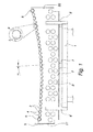
- shows a side view of the mould construction according to the invention.
- The described mould construction comprises a
framework 1 made of structural steel on which are supportedsupport plates 2 on vertical planes. There are several, for example 5,support plates 2 at a horizontal distance from one another. The support plates are parallel with one another. The curvature of the upper edge of thesupport plates 2 corresponds essentially to the desired bending curvature of the glass sheet. The upper edges of thesupport plates 2 compriseslots 3, in which are placedpipes 4, which form the mould surface. If necessary, there may be a non-woven mat or non-woven fabric on thepipes 4 for forming a uniform mould surface. Thesupport plates 2 andpipes 4 are made of stainless or acid-proof steel. - The
slots 3 are dimensioned to receive thepipes 4 with play but, however, in such a way that the upward movement of thepipes 4 from theslots 3 is prevented. The lengthening and shortening of the pipes due to the varying temperature will thus not affect the shape of the support surface. At the manufacturing stage, thepipes 4 are pushed in their longitudinal direction through theslots 3 of allsupport plates 2. During use, the pipes are free to expand by heat and will not warp. InFigure 1 , for the sake of clarity, thepipes 4 and theslots 3 are shown on a relatively larger scale than in the real construction, where also the number ofpipes 4 is about double that shown in the Figure. The diameter of thepipes 4 is between 15-25 mm and the gap between the pipes is between 4-8 mm. The wall thickness of thepipes 4 is 0.5-0.8 mm, that is, the pipes are relatively ductile and flexible. For this reason, there are at least four or fivesupport plates 2 divided over the length of the pipes. - The
support plates 2 are supported on the framework in such a way that one end of the mould surface is lower than the other end. In the embodiment shown this is implemented in such a way that thesupport plates 2 are higher at oneend 22 than theother end 21. In that case, the central axis of the parabola drawn through the centres of theslots 3 in the row of slots is correspondingly tilted, that is, deviates from the vertical plane towards thelower end 21 by angle a. Thesupport plates 2 at the lower end of the mould surface are provided withend stoppers 5 and the said difference in height, that is, the inclination of the mould surface is dimensioned so as to effect the resting of the edge of the glass sheet placed on the mould against the end stoppers 5 during the bending stage. The advantage of this construction is that the static friction between the glass sheet placed on the mould and the mould surface is converted into sliding friction evenly throughout and the glass sheet rests against thestoppers 5 all the time at the same point of the mould. Around thepipe 4 at the opposite end of the mould with respect to theend stoppers 5 is preferably a rotating, tubular non-wovenmetal fibre fabric 6 which facilitates the sliding of the other end of the glass sheet during bending. At the other end is preferably also ametal fibre pipe 6 around thepipe 4. - The
support plates 2 are fixed by their central area to theframework 1 by fasteners 7 which allow vertical movement but prevent horizontal movement. Theframework 1 comprises slot-like supports 8 for supporting the ends of thesupport plates 2 against lateral inclination, but slidingly in its longitudinal direction. This arrangement together with the loose fitting of thepipes 4 ensures that thesupport plates 2 will not warp as a result of thermal expansion. Thesupport plates 2 are, in addition, perforated in such a way that the proportion of theholes 9 is at least 25%, preferably more than 30%, of the surface area of thesupport plates 2. This lightens the structure and makes possible the circulation of air below the mould surface. - When the mould is built on the framework without fixed joints, the manufacture becomes repeatable and only assembly needs to be carried out on site.
Claims (10)
- A mould construction for bending glass sheets, the said mould construction comprising- a framework (1)- support plates (2) on vertical planes, the curvature of the upper edge of the plates essentially corresponding to the desired bending curvature of the glass sheet- slots (3) on the upper edges of the support plates (2)- pipes (4) forming the mould surface which are positioned in the said slots (3),
characterised in that the slots (3) are dimensioned with play with respect to the pipes, but to lock the upward movement of the pipes (4) from the slots (3), that the support plates (2) are supported on the framework (1) in such a way that one end of the mould surface is lower than the other end, that at the lower end of the mould surface the support plates (2) are provided with end stoppers (5), and that the said difference in height, that is, the inclination of the mould surface, is dimensioned so as to effect the resting of the edge of the glass sheet placed on the mould against the end stoppers (5) during the bending stage. - A mould construction as claimed in claim 1, characterised in that around the pipe (4) at the opposite end of the mould with respect to the end stoppers (5) is preferably a rotating, tubular non-woven metal fibre fabric (6).
- A mould construction as claimed in claim 1 or 2, characterised in that the support plates (2) are fixed by their central area to the framework (1) and that the framework (1) comprises supports (8) for supporting the ends of the support plates (2) against lateral inclination and slidingly in their longitudinal direction.
- A mould construction as claimed in any of the claims 1 to 3, characterised in that the support plates (2) are provided with holes (9) in such a way that the proportion of the holes (9) is at least 25% of the surface area of the support plates (2).
- A mould construction as claimed in any of the claims 1 to 4, characterised in that the framework (1) is made of structural steel and the support plates (2) and pipes (4) are made of stainless or acid-proof steel.
- A mould construction as claimed in any of the claims 1 to 5, characterised in that on the pipes (4) is a non-woven mat or non-woven fabric forming a uniform mould surface.
- A mould construction as claimed in any of the claims 1 to 6, characterised in that the support plates (2) are higher at one end (22) than the other end (21) and the central axis of the parabola drawn through the centres of the slots (3) in the row of slots is correspondingly tilted, that is, deviates from the vertical plane towards the lower end (21).
- A mould construction as claimed in any of the claims 1 to 7, characterised in that the outer diameter of the pipes (4) is between 15-25 mm and the gaps between the pipes are between 4-8 mm.
- A mould construction as claimed in claim 8, characterised in that the wall thickness of the pipes (4) is 0.5-0.8 mm and there are at least four support plates (2) divided over the length of the pipe.
- A mould construction as claimed in any of the claims 1 to 8, characterised in that the mould is built on the framework (1) without fixed joints.
Priority Applications (1)
| Application Number | Priority Date | Filing Date | Title |
|---|---|---|---|
| EP12161835.9A EP2644576A1 (en) | 2012-03-28 | 2012-03-28 | Mould construction for bending glass sheets |
Applications Claiming Priority (1)
| Application Number | Priority Date | Filing Date | Title |
|---|---|---|---|
| EP12161835.9A EP2644576A1 (en) | 2012-03-28 | 2012-03-28 | Mould construction for bending glass sheets |
Publications (1)
| Publication Number | Publication Date |
|---|---|
| EP2644576A1 true EP2644576A1 (en) | 2013-10-02 |
Family
ID=45888093
Family Applications (1)
| Application Number | Title | Priority Date | Filing Date |
|---|---|---|---|
| EP12161835.9A Withdrawn EP2644576A1 (en) | 2012-03-28 | 2012-03-28 | Mould construction for bending glass sheets |
Country Status (1)
| Country | Link |
|---|---|
| EP (1) | EP2644576A1 (en) |
Citations (4)
| Publication number | Priority date | Publication date | Assignee | Title |
|---|---|---|---|---|
| DE237064C (en) * | ||||
| WO1990003334A1 (en) * | 1988-09-28 | 1990-04-05 | Glamec Oy | Glass bending mold |
| WO1990003336A1 (en) | 1988-09-28 | 1990-04-05 | Glamec Oy | Heating, bending and cooling system for glass |
| EP0571287A1 (en) * | 1992-05-21 | 1993-11-24 | Saint-Gobain Vitrage International | Method and apparatus for bending glass sheets |
-
2012
- 2012-03-28 EP EP12161835.9A patent/EP2644576A1/en not_active Withdrawn
Patent Citations (4)
| Publication number | Priority date | Publication date | Assignee | Title |
|---|---|---|---|---|
| DE237064C (en) * | ||||
| WO1990003334A1 (en) * | 1988-09-28 | 1990-04-05 | Glamec Oy | Glass bending mold |
| WO1990003336A1 (en) | 1988-09-28 | 1990-04-05 | Glamec Oy | Heating, bending and cooling system for glass |
| EP0571287A1 (en) * | 1992-05-21 | 1993-11-24 | Saint-Gobain Vitrage International | Method and apparatus for bending glass sheets |
Similar Documents
| Publication | Publication Date | Title |
|---|---|---|
| US20130255322A1 (en) | Mould construction for bending glass sheets | |
| EP2167435B1 (en) | A method and apparatus for forming a double-curved panel from a flat panel | |
| JP2010229239A (en) | Heat insulating box for hot repair of carbonization chamber of coke oven and hot repair process for carbonization chamber | |
| JP5957613B2 (en) | Far-infrared multi-stage heating furnace for hot-press steel sheets | |
| CN103415629B (en) | The hot blast manifold construction method of blast funnace hot blast stove and hot blast manifold | |
| KR200488267Y1 (en) | Mould for manufacturing a multi-curved bent glass panel | |
| CN102524440A (en) | Tea drying machine | |
| EP2088371A3 (en) | Heat exchanger framework | |
| EP2644576A1 (en) | Mould construction for bending glass sheets | |
| ES2531466T3 (en) | Bending mold and procedure for the manufacture of contoured glass | |
| CN208860141U (en) | Multilayer insulation board supporting structure and flat reflective insulation screen, vacuum heating apparatus | |
| JP2010127591A (en) | Shelf assembly for burning | |
| CN101025336B (en) | Heating method and device for plate materials and retaining device for heating of plate materials | |
| JP6932722B2 (en) | Bottom support type boiler | |
| JP6615059B2 (en) | Additional columns for checker brick receiving hardware, checker brick receiving hardware and column expansion method | |
| CN109707046B (en) | Support connecting system for longitudinal reticulated shell structure | |
| JP6303744B2 (en) | Optical fiber manufacturing apparatus and optical fiber manufacturing method | |
| RU2703759C1 (en) | Additional column for support of checker bricks, support of checker bricks and method of column strengthening | |
| CN202425533U (en) | Tea leaf drying machine | |
| CN204959090U (en) | Multilayer structure molybdenum heat screen | |
| KR20190014860A (en) | Supporting apparatus and heating apparatus having the same | |
| CN110779331A (en) | Dynamic sealing structure for bottom of walking beam type heat treatment furnace | |
| JP5813229B2 (en) | Method for heating a long object in a radiation-type heating furnace and radiation-type heating furnace | |
| CN111316039B (en) | Boiler system with support structure | |
| CN104277860B (en) | A kind of cracking of ethylene furnace radiating pipe position-limited rack |
Legal Events
| Date | Code | Title | Description |
|---|---|---|---|
| PUAI | Public reference made under article 153(3) epc to a published international application that has entered the european phase |
Free format text: ORIGINAL CODE: 0009012 |
|
| AK | Designated contracting states |
Kind code of ref document: A1 Designated state(s): AL AT BE BG CH CY CZ DE DK EE ES FI FR GB GR HR HU IE IS IT LI LT LU LV MC MK MT NL NO PL PT RO RS SE SI SK SM TR |
|
| AX | Request for extension of the european patent |
Extension state: BA ME |
|
| STAA | Information on the status of an ep patent application or granted ep patent |
Free format text: STATUS: THE APPLICATION IS DEEMED TO BE WITHDRAWN |
|
| 18D | Application deemed to be withdrawn |
Effective date: 20140403 |