EP2644446A2 - Headrest for motor vehicle seats - Google Patents
Headrest for motor vehicle seats Download PDFInfo
- Publication number
- EP2644446A2 EP2644446A2 EP13382075.3A EP13382075A EP2644446A2 EP 2644446 A2 EP2644446 A2 EP 2644446A2 EP 13382075 A EP13382075 A EP 13382075A EP 2644446 A2 EP2644446 A2 EP 2644446A2
- Authority
- EP
- European Patent Office
- Prior art keywords
- moving part
- fixed part
- damping
- attached
- headrest
- Prior art date
- Legal status (The legal status is an assumption and is not a legal conclusion. Google has not performed a legal analysis and makes no representation as to the accuracy of the status listed.)
- Granted
Links
- 238000013016 damping Methods 0.000 claims abstract description 62
- 230000000903 blocking effect Effects 0.000 claims description 50
- 238000000926 separation method Methods 0.000 claims 2
- 239000006260 foam Substances 0.000 description 8
- 230000001681 protective effect Effects 0.000 description 4
- 230000000694 effects Effects 0.000 description 3
- 238000010521 absorption reaction Methods 0.000 description 1
- 230000009931 harmful effect Effects 0.000 description 1
Images


Classifications
-
- B—PERFORMING OPERATIONS; TRANSPORTING
- B60—VEHICLES IN GENERAL
- B60N—SEATS SPECIALLY ADAPTED FOR VEHICLES; VEHICLE PASSENGER ACCOMMODATION NOT OTHERWISE PROVIDED FOR
- B60N2/00—Seats specially adapted for vehicles; Arrangement or mounting of seats in vehicles
- B60N2/24—Seats specially adapted for vehicles; Arrangement or mounting of seats in vehicles for particular purposes or particular vehicles
- B60N2/42—Seats specially adapted for vehicles; Arrangement or mounting of seats in vehicles for particular purposes or particular vehicles the seat constructed to protect the occupant from the effect of abnormal g-forces, e.g. crash or safety seats
- B60N2/427—Seats or parts thereof displaced during a crash
- B60N2/42727—Seats or parts thereof displaced during a crash involving substantially rigid displacement
-
- B—PERFORMING OPERATIONS; TRANSPORTING
- B60—VEHICLES IN GENERAL
- B60N—SEATS SPECIALLY ADAPTED FOR VEHICLES; VEHICLE PASSENGER ACCOMMODATION NOT OTHERWISE PROVIDED FOR
- B60N2/00—Seats specially adapted for vehicles; Arrangement or mounting of seats in vehicles
- B60N2/24—Seats specially adapted for vehicles; Arrangement or mounting of seats in vehicles for particular purposes or particular vehicles
- B60N2/42—Seats specially adapted for vehicles; Arrangement or mounting of seats in vehicles for particular purposes or particular vehicles the seat constructed to protect the occupant from the effect of abnormal g-forces, e.g. crash or safety seats
- B60N2/427—Seats or parts thereof displaced during a crash
- B60N2/42772—Seats or parts thereof displaced during a crash characterised by the triggering system
- B60N2/4279—Seats or parts thereof displaced during a crash characterised by the triggering system electric or electronic triggering
-
- B—PERFORMING OPERATIONS; TRANSPORTING
- B60—VEHICLES IN GENERAL
- B60N—SEATS SPECIALLY ADAPTED FOR VEHICLES; VEHICLE PASSENGER ACCOMMODATION NOT OTHERWISE PROVIDED FOR
- B60N2/00—Seats specially adapted for vehicles; Arrangement or mounting of seats in vehicles
- B60N2/80—Head-rests
- B60N2/806—Head-rests movable or adjustable
- B60N2/809—Head-rests movable or adjustable vertically slidable
-
- B—PERFORMING OPERATIONS; TRANSPORTING
- B60—VEHICLES IN GENERAL
- B60N—SEATS SPECIALLY ADAPTED FOR VEHICLES; VEHICLE PASSENGER ACCOMMODATION NOT OTHERWISE PROVIDED FOR
- B60N2/00—Seats specially adapted for vehicles; Arrangement or mounting of seats in vehicles
- B60N2/80—Head-rests
- B60N2/888—Head-rests with arrangements for protecting against abnormal g-forces, e.g. by displacement of the head-rest
Definitions
- the present invention is related to a headrest for motor vehicle seats.
- Headrests referred to as active headrests are known, such active headrests comprising two parts, a fixed part and a moving part, the moving part being movable from a rest position, in which the moving part is attached to the fixed part, to an active position in the event that the vehicle receives a rear impact.
- the moving part In said active position, the moving part is separated from the fixed part and moved towards the head of the occupant in the seat, thereby reducing the distance that the head travels until reaching its support in the headrest, and therefore reducing the risk of said occupant suffering whiplash.
- ES2344496A1 describes a headrest for motor vehicle seats comprising a fixed part, a moving part movable with respect to said fixed part from a rest position to an active position, connection means connecting said fixed part and said moving part to determine the path and the position of the moving part, and a drive system comprising a drive device for driving and moving the moving part with respect to the fixed part.
- the object of the invention is to provide an active headrest as defined in the claims.
- the headrest of the invention comprises a fixed part, a moving part movable with respect to said fixed part from a rest position to an active position, connection means connecting said fixed part and said moving part to determine the path and the position of the moving part, and a drive system comprising a drive device for driving and moving the moving part with respect to the fixed part in the event of a crash.
- the headrest also comprises damping means allowing the movement of at least one portion of the moving part to a forward position with respect to the active position, and allowing the backward movement to the active position after the impact of the user's head, absorbing energy in said backward movement.
- the objective is for the active position to remain fixed, such that when these headrests go into the active position they are blocked and prepared to absorb the greatest possible amount of energy by means of incorporating padding means, such as protective foams for example, maintaining this position in response to the efforts exerted on the moving part by the head of the occupant in the seat.
- padding means such as protective foams for example
- damping means In the headrest of the invention, in addition to the conventional padding means arranged in the moving part for receiving the impact of the user's head, damping means are included, said damping means allow taking at least one portion of the moving part further forward with respect to the defined active position, such that when the head of the occupant in the seat impacts against said at least one portion of the moving part, as it moves backwards after the received impact, the damping means allow said at least one portion of the moving part to move backwards to the defined active position, and in this backward movement said damping means absorb energy, reducing the velocity of the head of the occupant in the seat caused by the forward movement of the vehicle seat.
- both the seat and the headrest have a lower level of internal energy due to the damping means, which results in a lower release of elastic energy at the time of the rebound than the energy that would be released without the damping means, causing the head of the occupant in the seat to lose velocity in the rebound and producing less damage.
- FIG. 1 shows a perspective view of a first embodiment of the headrest 1 of the invention in a rest position.
- Said headrest 1 comprises a fixed part 2, a moving part 3 movable with respect to said fixed part 2 from a rest position "O" to an active position "A", indicated in Figure 3 , and connection means 4 connecting the fixed part 2 with the moving part 3.
- the connection means 4 comprise an upper arm 31 and two lower lateral connection means 32.
- the upper arm 31 comprises two side levers 33, one of the ends of each side lever 33 pivoting with respect to a respective shaft 34 arranged in the fixed part 2, both shafts 34 being coaxial, and the other end of each side lever 33 pivoting with respect to a respective shaft 35 of the moving part 3, both shafts 35 being coaxial.
- the upper arm 31 also comprises a central body 36 whereby both side levers 33 are attached to one another.
- the lower connection means 32 comprise a guide arm 37 attached to the moving part 3 and a channel 38 arranged in the fixed part 2.
- the moving part 3 is guided to the fixed part 2 by means of the connection between the guide arm 37 and the channel 38, and the inclination of said moving part 3 at all points of the path from the rest position "O" to the active position "A" is determined by the connection between said guide arm 37 and the channel 38, said connection being defined by the design of the contour of the guide arm 37 which fits with the height of the channel 38 for all the positions of the desired path of the moving part 3.
- the guide arm 37 further comprises a stop 39 which is housed in one of the transverse holes of said guide arm 37 and delimits the furthest position of the moving part 3 with respect to the fixed part 2; the guide arm 37 can have several transverse holes, such that different end positions of the moving part 3 can be chosen according to which hole houses the stop 39.
- the path and the end position of the moving part 3 are thus defined with the design provided for the guide arm 37 and for the channel 38, as well as with the choice of the position of the stop 39.
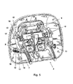
- FIG 2 shows a longitudinal section perspective view of the embodiment of the headrest 1 of Figure 1 , the moving part 3 being in the rest position.
- Said headrest 1 is a headrest referred to as an active headrest given that it comprises a drive system, said drive system comprising a drive device 5, the function of which is to produce motion, i.e., it serves to drive and move the moving part 3 with respect to the fixed part 2 in the event of a crash.
- this drive device 5 comprises a pyrotechnic drive device 26, said pyrotechnic drive device 26 being supported in this embodiment in the fixed part 2 and being firmly attached to it.
- Said pyrotechnic drive device 26 comprises a bolt 27 which is a shaft that can be moved from a rest position to an end position when the charge of the pyrotechnic drive device 26 is activated.
- the drive system also comprises an articulated device 40 which is pivotally attached to the fixed part 2 and to the moving part 3 at its ends and has at least one pivoting intermediate connection 41, the drive device 5 operatively cooperating with said articulated device 40.
- said articulated device 40 comprises a first arm 42 pivotally attached to the fixed part 2 at one of its ends with respect to a shaft 43 and to the pivoting intermediate connection 41, and a second arm 44 attached to the pivoting intermediate connection 41 at one of its ends and the other end pivoting with respect to a shaft 45 of the moving part 3.
- the second arm 44 opens into two parts ( Figure 2 only shows one of the parts) in the area of the pivoting intermediate connection 41, such that it braces the first arm 42 in said connection.
- FIG 3 shows a schematic profile view of the embodiment of the headrest 1 of Figure 1 , the moving part 3 being in the active position "A".
- the drive device 5 When the drive device 5 is activated in the moment in which the vehicle is in a crash, the drive device 5 moves the moving part 3 with respect to the fixed part 2 from the rest or passive position "O" to the active position "A".
- the purpose is of this type of active headrest is to restrain the user's head in the active position "A" before it acquires too much velocity due to the vehicle crash and thus prevent the so-called “whiplash” in the neck.
- This active position "A” is a position precisely calculated by each vehicle manufacturer taking into account each seat and headrest model.
- Said active position "A” usually has to remain fixed, so when all headrests of this type go to said position they are blocked, and they can thus maintain this active position "A” in response to the efforts exerted on the moving part 3 by the user's head.
- one of the parameters measured is the forward rebound velocity of the dummy's head, which substitutes the user's head.
- the user's head impacts with the moving part 3 of the headrest 1 which is in the active position "A", and both the seat and the headrest 1 release all the elastic energy they have acquired, driving said user's head forward like a catapult, producing a very harmful effect.
- the active position "A" is calculated as precisely as possible, such that since said position is blocked, the rebound of the user's head, and therefore the velocity at which the head bounces off the headrest , is the lowest possible.
- the foam covering, for example a protective foam, of the moving part 3 of the headrest 1 helps this arrangement of the moving part 3, such that when the user's head impacts, said foams absorb energy and therefore reduce the rebound velocity of the user's head to a certain extent.
- the moving part 3 of the headrest 1 comprises two portions, a first portion 6 attached to the fixed part 2 by means of the connection means 4, and a second portion 7 associated with the first portion 6 and usually covered with protective foams.
- the drive device 5 allows moving the moving part 3 to the active position "A", such that when this movement occurs, both the first portion 6 and the second portion 7 move to said active position "A", as can be observed in Figure 3 .
- Figure 4 shows a schematic profile view of the headrest 1 of the embodiment of the headrest 1 of Figure 1 , the second portion 7 of the moving part 3 being located in a forward position "AD" with respect to the active position "A".
- the headrest 1 of the invention comprises damping means 8 allowing the movement of the second portion 7 to a forward position "AD” with respect to the active position "A", and after the impact of the user's head with the second portion 7 occurs, allowing the backward movement of said second portion 7, which had previously been moved forward to the forward position "AD", to the active position "A", said damping means 8 absorbing energy in said backward movement.
- the damping means 8 comprise a damping device 9 and a blocking mechanism 10 for said damping device 9.
- Figure 5 shows a rear view of the moving part 3 of the embodiment of the headrest 1 of Figure 1 .
- the damping device 9 of the damping means 8 comprises two identical damping units 11 arranged on both sides of the moving part 3, which allow the movement of the second portion 7 of the moving part 3 with respect to the first portion 6, and two identical guiding units 12 arranged on both sides of the moving part 3 which allow defining the direction of movement of the second portion 7 of the moving part 3 with respect to the rest of the moving part 3 when the damping units 11 move the second portion 7.
- Each damping unit 11 comprises elastic means 13, preferably a spring, but said means can be another type of elastic element, a support 14 attached to the second portion 7 at one end, and a damping guide 15 attached to the first portion 6 with a groove therein that traverses it, the support 14 being introduced in said groove, and one end of the elastic means 13 being attached to the free end of the support 14, and the other end of the elastic means 13 being attached to an end of the damping guide 15 located on the side of the second portion 7.
- Each guiding unit 12 comprises a guide 16 attached to the second portion 7 at one end, said guide 16 comprising a protuberance 17 at the free end opposite the attachment with the second portion 7.
- the guiding unit 12 also comprises a guiding support 18 attached to the first portion 6 with a groove therein that traverses it, the guide 16 being introduced in said groove. Therefore, when the second portion 7 is moved to the forward position "AD" driven by the damping unit 11, the elastic means 13 define the movement, the second portion 7 is moved, guided by the guiding unit 12, and the protuberance 17 abuts the guide 16 in the groove of the guiding support 18, the second portion 7 not being able to move further forward.
- FIG 6 shows a perspective view of the blocking mechanism of the embodiment of the headrest 1 of Figure 1 .
- the blocking mechanism 10 of the damping means 8 comprises two identical drive cams 19, each of which having a free end 20 with which the drive device 5 cooperates, having a projection 21 close to said free end 20 in the lower part thereof arranged for cooperating with the fixed part 2 of headrest 1.
- the drive cams 19 also comprise a pivoting end 22 which pivots in a shaft (not shown in Figure 6 ) attached to the first portion 6 of the moving part 3.
- the blocking mechanism 10 also comprises a retaining cam 23 integrally attached to the pivoting end 22 of the drive cams 19 at one end, and the other end forming a retaining end 24 arranged for cooperating with the second portion 7.
- the second portion 7 of the moving part 3 comprises retaining means 25, and the blocking mechanism 10 is pivotally arranged in the first portion 6 of the moving part 3 by means of the pivoting end 22 of the drive cams 19, with the retaining end 24 of the retaining cam 23 arranged facing the retaining means 25 of the second portion 7, such that the retaining means 25 and the retaining cam 23 are attached to one another when the second portion 7 has not been moved to the forward position "AD", or in other words, when the damping means 8 are blocked.
- This blocking situation occurs either when the headrest 1 is in the rest position, as can be observed in Figure 2 , or when the second portion 7 of the moving part 3 is in the active position "A", as can be observed in Figure 3 , and in said situations the elastic means 13 of the damping unit 11 are tensed and therefore potentially loaded, said elastic means 13 being a tension spring in this embodiment, such that it is stretched when it is blocked, and when the second portion 7 is released and moved to the forward position "AD", the tension is released from the spring, making it contract.
- the fixed part 2 and the moving part 3 are attached to one another and form a single compact body.
- the pyrotechnic drive device 26 is not activated, and the bolt 27 is in the rest situation, i.e., withdrawn in said pyrotechnic drive device 26.
- the drive device 5 also comprises a drive runner with a shaft 29 fitting in said runner, the shaft 29 of the drive runner being located in its lower position, and the bolt 27 is located below the central part of the shaft 29 of the drive runner.
- the fixed part 2 of the headrest 1 of the invention comprises two fixed hooks 30 integral with said fixed part 2, said fixed hooks 30 cooperating with the moving part 3 by means of the projection 21 of the drive cam 19 of the blocking mechanism 10, such that the headrest 1 is prevented from being able to be opened manually and from being able to access the inside thereof and manipulate the different elements thereof, as can be observed in Figure 7 showing a schematic profile view of the embodiment of the headrest 1 of Figure 1 , the moving part 3 being in the rest position.
- each drive cam 19 is located above the ends of the shaft 29 of the drive runner, and the retaining end 24 of the retaining cam 23 of said drive cams 19 is cooperating, engaging the retaining means 25 of the second portion 7, the damping means 8 being blocked.
- the pyrotechnic charge of the pyrotechnic drive device 26 is activated when an electric signal arrives from a sensor.
- the bolt 27 is then activated and goes from the rest position to the end position. Two steps occurring one after the other are contemplated in that movement between the two positions. In the first step, the bolt 27 travels the distance separating it from the lower part of the shaft 29 of the drive runner, contacts said shaft 29 and drives it, moving it. With the movement of the shaft 29, the upper part of said shaft 29 contacts the lower part of the free end 20 of each drive cam 19, causing a movement of said drive cams 19.
- the bolt 27 continues the movement and travels the distance separating it to its end position.
- the central upper part of the shaft 29 of the drive runner contacts the lower part of the first arm 42 of the articulated device 40 pushing it, and thus drives and moves it.
- the first arm 42 is pivotally attached to the fixed part 2 at one of its ends and to the pivoting connection 41 at its other end, and the second arm 44 of the articulated device 40 is attached to the pivoting connection 41 at one end and is pivotally attached to the moving part 3 at its other end, said second arm 44 is driven, also pivoting in said pivoting connection 41.
- the moving part 3 is thus driven and moved with respect to the fixed part 2 from a rest position "O" to the active position "A", as can be observed in Figure 3 .
- Figure 9 shows a rear perspective view of a second embodiment of the headrest 1 of the invention in the rest position.
- Said headrest 1 comprises a fixed part 2, a moving part 3 movable with respect to said fixed part 2 from a rest position "O" to an active position "A".
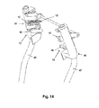
- Figure 10 shows a schematic profile view of the embodiment of Figure 9 , the moving part 3 being at rest
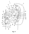
- Figure 11 shows a schematic profile view of the embodiment of Figure 9 , the moving part 3 being in the active position "A”
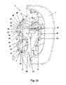
- Figure 16 shows a rear perspective view of the embodiment of Figure 9 , the moving part 3 being in the active position "A”.
- Connection means 4 connect the fixed part 2 with the moving part 3.
- the connection means 4 comprise an upper arm 31 and two lower lateral connection means 32.
- the upper arm 31 comprises two side levers 33, one of the ends of each side lever 33 pivoting with respect to a respective shaft 34 arranged in the fixed part 2, both shafts 34 being coaxial, and the other end of each side lever 33 pivoting with respect to a respective shaft 35 of the moving part 3, both shafts 35 being coaxial.
- the upper arm 31 also comprises a central body 36 whereby both side levers 33 are attached to one another.
- the lower connection means 32 comprise a guide arm 37 attached to the moving part 3 and a channel 38 arranged in the fixed part 2.
- the moving part 3 is guided to the fixed part 2 by means of the connection between the guide arm 37 and the channel 38, and the inclination of said moving part 3 at all points of the path from the rest position "O" to the active position "A" is determined by the connection between said guide arm 37 and the channel 38, said connection being defined by the design of the contour of the guide arm 37 which fits with the height of the channel 38 for all the positions of the desired path of the moving part 3.
- the guide arm 37 further comprises a stop 39 which is housed in one of the transverse holes of said guide arm 37 and delimits the furthest position of the moving part 3 with respect to the fixed part 2; the guide arm 37 can have several transverse holes, such that different end positions of the moving part 3 can be chosen according to which hole houses the stop 39.
- the path and the end position of the moving part 3 are thus defined with the design provided for the guide arm 37 and for the channel 38, as well as with the choice of the position of the stop 39.
- the headrest 1 is an active headrest comprising a drive system, said drive system comprising a drive device 5 for driving and moving the moving part 3 with respect to the fixed part 2.
- this drive device 5 comprises a pyrotechnic drive device 26, said pyrotechnic drive device 26 being supported in the fixed part 2.
- Said pyrotechnic drive device 26 comprises a bolt 27 that can be moved from a rest position to an end position when the charge of the pyrotechnic drive device 26 is activated.
- the drive system also comprises an articulated device 40 which is pivotally attached to the fixed part 2 and to the moving part 3 at its ends and has at least one pivoting intermediate connection 41, the drive device 5 operatively cooperating with said articulated device 40.
- said articulated device 40 comprises a first arm 42 pivotally attached to the fixed part 2 at one of its ends with respect to a shaft 43 and to the pivoting intermediate connection 41, and a second arm 44 attached to the pivoting intermediate connection 41 at one of its ends and the other end pivoting with respect to a shaft 45 of the moving part 3.
- the second arm 44 opens into two parts ( Figure 11 only shows one of the parts) in the area of the pivoting intermediate connection 41, such that it braces the first arm 42 in said attachment.
- the drive device 5 When the drive device 5 is activated in the moment in which the vehicle is in a crash, the drive device 5 moves the moving part 3 with respect to the fixed part 2 from the rest or passive position "O" to the active position "A".
- said fixed part 2 of the headrest 1 comprises a structure 46 attached to rods 47 which in turn attach it to the vehicle seat, and a support 48 associated with said structure 46.
- the support 48 is attached to the moving part 3 by means of the connection means 4, and the drive device 5 allows moving the moving part 3 to the active position "A" with respect to the support 48, and therefore with respect to the structure 46.
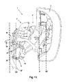
- Figure 13 shows a schematic profile view of the embodiment of Figure 9 , the support 48 of the fixed part 2 being located in a forward position "Ad” with respect to the structure 46, and the moving part 3 being located in a forward position "AD” with respect to the active position "A".
- the headrest 1 of the invention comprises in this second embodiment damping means 8 allowing the movement of the support 48 of the fixed part 2 to the forward position "Ad", and thus allowing the movement of the moving part 3 to the forward position "AD" with respect to the active position "A".
- the damping means 8 allow the backward movement of said moving part 3 to the active position "A", absorbing energy in said backward movement.
- the damping means 8 comprise a damping device 9 and a blocking mechanism 10 for said damping device 9, as can be observed in Figure 9 .
- Figure 12 shows the damping device 9 of the damping means 8 comprising in this second embodiment two identical damping units 11 arranged on both sides of the fixed part 2, which allow the movement of the support 48 of the fixed part 2 with respect to the structure 46, and two identical guiding units 12 arranged on both sides of the fixed part 2, which allow defining the direction of movement of the support 48 of the fixed part 2 with respect to the structure 46 when the damping units 11 move the support 48.
- each damping unit 11 comprises elastic means 13, preferably a spring, but said means can be another type of elastic element, a support 14 integrally attached to the support 48 at one end, and a damping guide 15 attached to the structure 46, the elastic means 13 being introduced in said guide 15, one end of the elastic means 13 being attached to a hole of the support 14, and the other end of the elastic means 13 being attached to a hole at one end of the damping guide 15.
- Each guiding unit 12 comprises a guide 16 integrally attached to the structure 46, said guide 16 comprising a protuberance (not shown in the drawings) at the end corresponding to the rear part of the support 48, and a guiding support 18 attached to the support 48 with a groove therein that traverses it, the guide 16 being introduced in said groove. Therefore, when the support 48 is moved to the forward position "Ad" driven by the damping unit 11, the elastic means 13 define the movement, the support 48 being moved as the guide 16 slides along the groove of the guiding support 18 until reaching the abutting protuberance, the support 48 not being able to move further forward.
- Figure 15 shows a perspective view of the blocking mechanism 10 of the embodiment of Figure 9 .
- the blocking mechanism 10 of the damping means 8 comprises a drive cam 19 with a free end 20 and a pivoting end 22 which pivots in a shaft 49 which is attached to the support 48 of the fixed part 2.
- the blocking mechanism 10 also comprises a retaining cam 23 integrally attached to the pivoting end 22 of the drive cam 19 at one end, and the other end forming a retaining end 24 arranged for cooperating with the structure 46 of the fixed part 2.
- the structure 46 of the fixed part 2 comprises a retaining rod 50
- the blocking mechanism 10 is pivotally arranged in the support 48 of the fixed part 2 by means of the pivoting end 22 of the drive cam 19, with the retaining end 24 of the retaining cam 23 having an opening arranged facing the retaining rod 50 of the structure 46 and allowing the rod 50 to be able to fit in said opening; the retaining cam 23 and the retaining rod 50 are thus attached to one another since said rod 50 fits in the opening of the retaining end 24 when the support 48 has not been moved to the forward position "Ad", or in other words, when the damping means 8 are blocked.
- This blocking situation occurs either when the headrest 1 is in the rest position, as can be observed in Figure 10 , or when the support 48 of the fixed part 2 is in the rest situation and the moving part 3 is in the active position "A", as can be observed in Figure 11 .
- the elastic means 13 of the damping unit 11 is tensed and therefore potentially loaded, said elastic means 13 being a tension spring in this embodiment, such that it is stretched when it is blocked, and when the support 48 is released and moved to the forward position "Ad”, and therefore the moving part 3 is moved to the forward position "AD”, the tension is released from the spring, making it contract.
- the support 48 of the fixed part 2 comprises elastic means 51, preferably a spring, but the means can be another type of elastic element, attached to a shaft 52 at one end, which shaft is in turn attached to the support 48 at its ends, and the other end of the elastic means 51 is free and in contact with the back face of the retaining end 24 of the retaining cam 23.
- the elastic means 51 thus push the retaining end 24 against the retaining rod 50.
- the support 48 of the fixed part 2 also comprises a blocking device 53, which comprises elastic means 54, preferably a spring, but the means can be another type of elastic element, with one end attached to the support 48, and the blocking device 53 also comprises an L-shaped blocking element 55.
- the blocking element 55 comprises one side of the L projecting towards the outside of the support 48 and is attached to the other end of the elastic means 54 at its end, and the other side of the L is a U-shaped prolongation having a shaft 56 at the open end crossing the U and leaving a gap between said shaft 56 and the base of the U.
- the fixed part 2 and the moving part 3 are attached to one another and form a single compact body.
- the pyrotechnic drive device 26 is not activated, and the bolt 27 is in the rest situation, i.e., withdrawn in said drive device 26.
- the drive device 5 also comprises a drive runner with a shaft 29 fitting in said runner, the shaft 29 of the drive runner being located in its lower position, and the bolt 27 is located below the central part of the shaft 29 of the drive runner.
- the fixed part 2 of the headrest 1 of the invention comprises two fixed hooks 30 integral with said fixed part 2 and attached to a drive guide where the drive runner slides, as can be observed in Figure 12 , said fixed hooks 30 cooperating with the moving part 3 by means of a projection 21 of two hooks 57 which said moving part 3 comprises, as can be observed in Figure 11 , and attached to said moving part 3 by means of elastic connection means (not shown in the figure).
- the headrest 1 is thus prevented from being able to be opened manually and from being able to access the inside thereof and manipulate the different elements thereof.
- the free end 20 of the drive cam 19 of the blocking mechanism 10 is located at the height of the shaft 56 of the blocking element 55, pushing it due to the effect of the pushing exerted by the elastic means 51 and of the pivoting caused by the pivoting end 22 about the shaft 49, and the retaining end 24 of the retaining cam 23 is cooperating, engaging the retaining rod 50 of the structure 46, the damping means 8 being blocked.
- the pyrotechnic charge of the pyrotechnic drive device 26 is activated when an electric signal arrives from a sensor.
- the bolt 27 is then activated and goes from the rest position to the end position; two steps occurring one after the other are contemplated in that movement between the two positions.
- the bolt 27 travels the distance separating it from the lower part of the shaft 29 of the drive runner, contacts said shaft 29 and drives it, moving it. With the movement of the shaft 29, the drive runner contacts the lower part of the free end of each hook 57, causing a movement of said hooks 57.
- said hooks 57 are attached to the moving part 3 by means of elastic connections, the latter allow the pivoting of the hooks 57, causing a release of the engagement of said hooks 57 in their projections 21 with respect to the fixed hooks 30, the fixed part 2 and moving part 3 no longer being attached to one another and forming a single compact body.
- the bolt 27 continues the movement and travels the distance separating it to its end position; after traveling the first step, the central upper part of the shaft 29 of the drive runner contacts the lower part of the first arm 42 of the articulated device 40 pushing it, and thus drives and moves it.
- said driving since the first arm 42 is pivotally attached to the fixed part 2 at one of its ends, said first arm 42, having a protuberance 58 at the end rotating about the shaft 43, and in contact with the shaft 56 of the blocking element 55 in the rest situation of the headrest 1, on the opposite side in which the free end 20 of the drive cam 19 pushes said shaft 56, rotates about the shaft 43 pushing the shaft 56, and thus overcoming the pushing exerted by the free end 20 and due to the elastic means 51.
- the free end 20 of the drive cam 19 is introduced into the gap formed between the shaft 56 and the base of the U of the L-shaped part, said end 20 being blocked by the effect of the traction force exerted by the elastic means 54 on the blocking element 55.
- the blocking mechanism 10 can thus rotate freely about the shaft 49 due the effect of the pushing of the elastic means 51, the opening of the retaining end 24 of the retaining cam 23 no longer cooperating with the retaining rod50, causing a release of the support 48 with respect to its attachment of the structure 46.
- first arm 42 of the articulated device 40 is pivotally attached to the pivoting connection 41 at its other end, and the second arm 44 of the articulated device 40 is attached to the pivoting connection 41 at one end and is pivotally attached to the moving part 3 at its other end, said second arm 44 is driven, also pivoting in said pivoting connection 41.
- the moving part 3 is thus driven and moved with respect to the fixed part 2 from a rest position "O" to the active position "A", as can be observed in Figure 11 .
- the blocking system for blocking the headrest acts to keep the moving part 3 in the active position "A", and due to the pushing of the elastic means 51, the blocking mechanism 10 receives the retaining rod 50 with the opening of the retaining end 24 of the retaining cam 23; due to the backward driving, the free end 20 of the drive cam 19 comes out of the gap formed between the shaft 56 and the base of the U of the blocking element 55, which has been moved backwards as a consequence of the force of the elastic means 54, now leaving the free end 20 with the shaft 56 of the blocking element 55 facing one another due to the force exerted by the elastic means 51 and thereby blocking the blocking mechanism 10.
- the retaining rod 50 of the structure 46 and the retaining end 24 of the retaining cam 23 of the blocking mechanism 10 thus engage one another, the attachment of the support 48 and of the structure 46 being blocked.
- the foam covering, for example protective foams, of the at least one portion of the moving part 3 of the headrest 1 helps this energy absorption occurring in the backward movement from the forward position "AD" to the active position "A", such that when the user's head impacts, said foam absorbs energy and therefore reduce the rebound velocity of the user's head to a certain extent.
Landscapes
- Engineering & Computer Science (AREA)
- Aviation & Aerospace Engineering (AREA)
- Transportation (AREA)
- Mechanical Engineering (AREA)
- Seats For Vehicles (AREA)
- Chair Legs, Seat Parts, And Backrests (AREA)
Abstract
Description
- The present invention is related to a headrest for motor vehicle seats.
- Headrests referred to as active headrests are known, such active headrests comprising two parts, a fixed part and a moving part, the moving part being movable from a rest position, in which the moving part is attached to the fixed part, to an active position in the event that the vehicle receives a rear impact. In said active position, the moving part is separated from the fixed part and moved towards the head of the occupant in the seat, thereby reducing the distance that the head travels until reaching its support in the headrest, and therefore reducing the risk of said occupant suffering whiplash.
-
ES2344496A1 - The object of the invention is to provide an active headrest as defined in the claims.
- The headrest of the invention comprises a fixed part, a moving part movable with respect to said fixed part from a rest position to an active position, connection means connecting said fixed part and said moving part to determine the path and the position of the moving part, and a drive system comprising a drive device for driving and moving the moving part with respect to the fixed part in the event of a crash. The headrest also comprises damping means allowing the movement of at least one portion of the moving part to a forward position with respect to the active position, and allowing the backward movement to the active position after the impact of the user's head, absorbing energy in said backward movement.
- In the headrests of the prior art, the objective is for the active position to remain fixed, such that when these headrests go into the active position they are blocked and prepared to absorb the greatest possible amount of energy by means of incorporating padding means, such as protective foams for example, maintaining this position in response to the efforts exerted on the moving part by the head of the occupant in the seat.
- In the headrest of the invention, in addition to the conventional padding means arranged in the moving part for receiving the impact of the user's head, damping means are included, said damping means allow taking at least one portion of the moving part further forward with respect to the defined active position, such that when the head of the occupant in the seat impacts against said at least one portion of the moving part, as it moves backwards after the received impact, the damping means allow said at least one portion of the moving part to move backwards to the defined active position, and in this backward movement said damping means absorb energy, reducing the velocity of the head of the occupant in the seat caused by the forward movement of the vehicle seat. Therefore both the seat and the headrest have a lower level of internal energy due to the damping means, which results in a lower release of elastic energy at the time of the rebound than the energy that would be released without the damping means, causing the head of the occupant in the seat to lose velocity in the rebound and producing less damage.
- These and other advantages and characteristics of the invention will be made evident in the light of the drawings and the detailed description of the invention.
-
-
Figure 1 shows a perspective view of a first embodiment of the headrest of the invention in the rest position. -
Figure 2 shows a longitudinal section perspective view of the embodiment ofFigure 1 , the moving part being in the rest position. -
Figure 3 shows a schematic profile view of the embodiment ofFigure 1 , the moving part being in the active position. -
Figure 4 shows a schematic profile view of the embodiment ofFigure 1 , the second portion of the moving part being located in a forward position with respect to the active position. -
Figure 5 shows a rear view of the moving part of the embodiment ofFigure 1 . -
Figure 6 shows a perspective view of the blocking mechanism of the embodiment ofFigure 1 . -
Figure 7 shows a schematic profile view of the embodiment ofFigure 1 , the moving part being in the rest position. -
Figure 8 shows a longitudinal section perspective view of the embodiment ofFigure 1 , the second portion of the moving part being located in the forward position with respect to the active position. -
Figure 9 shows a rear perspective view of a second embodiment of the headrest of the invention in the rest position. -
Figure 10 shows a schematic profile view of the embodiment ofFigure 9 , the moving part being at rest. -
Figure 11 shows a schematic profile view of the embodiment ofFigure 9 , the moving part being in the active position. -
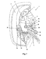
Figure 12 shows a front perspective view of the fixed part of the embodiment ofFigure 9 . -
Figure 13 shows a schematic profile view of the embodiment ofFigure 9 , the support of the fixed part being located in a forward position with respect to the structure of the fixed part, and the moving part being located in a forward position with respect to the active position. -
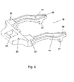
Figure 14 shows a front perspective view of the structure of the fixed part of the embodiment ofFigure 9 . -
Figure 15 shows a detailed perspective view of the blocking mechanism of the embodiment ofFigure 9 . -
Figure 16 shows a rear perspective view of the embodiment ofFigure 9 , the moving part being in the active position. -
Figure 1 shows a perspective view of a first embodiment of theheadrest 1 of the invention in a rest position. Saidheadrest 1 comprises afixed part 2, a movingpart 3 movable with respect to saidfixed part 2 from a rest position "O" to an active position "A", indicated inFigure 3 , and connection means 4 connecting thefixed part 2 with the movingpart 3. In this embodiment, the connection means 4 comprise anupper arm 31 and two lower lateral connection means 32. Theupper arm 31 comprises two side levers 33, one of the ends of each side lever 33 pivoting with respect to arespective shaft 34 arranged in thefixed part 2, bothshafts 34 being coaxial, and the other end of each side lever 33 pivoting with respect to arespective shaft 35 of the movingpart 3, bothshafts 35 being coaxial. Theupper arm 31 also comprises acentral body 36 whereby bothside levers 33 are attached to one another. - The lower connection means 32 comprise a
guide arm 37 attached to the movingpart 3 and achannel 38 arranged in thefixed part 2. The movingpart 3 is guided to thefixed part 2 by means of the connection between theguide arm 37 and thechannel 38, and the inclination of said movingpart 3 at all points of the path from the rest position "O" to the active position "A" is determined by the connection between saidguide arm 37 and thechannel 38, said connection being defined by the design of the contour of theguide arm 37 which fits with the height of thechannel 38 for all the positions of the desired path of themoving part 3. Theguide arm 37 further comprises astop 39 which is housed in one of the transverse holes of saidguide arm 37 and delimits the furthest position of the movingpart 3 with respect to thefixed part 2; theguide arm 37 can have several transverse holes, such that different end positions of the movingpart 3 can be chosen according to which hole houses thestop 39. The path and the end position of the movingpart 3 are thus defined with the design provided for theguide arm 37 and for thechannel 38, as well as with the choice of the position of thestop 39. -
Figure 2 shows a longitudinal section perspective view of the embodiment of theheadrest 1 ofFigure 1 , the movingpart 3 being in the rest position. Saidheadrest 1 is a headrest referred to as an active headrest given that it comprises a drive system, said drive system comprising adrive device 5, the function of which is to produce motion, i.e., it serves to drive and move the movingpart 3 with respect to thefixed part 2 in the event of a crash. In this embodiment, thisdrive device 5 comprises apyrotechnic drive device 26, saidpyrotechnic drive device 26 being supported in this embodiment in thefixed part 2 and being firmly attached to it. Saidpyrotechnic drive device 26 comprises abolt 27 which is a shaft that can be moved from a rest position to an end position when the charge of thepyrotechnic drive device 26 is activated. The drive system also comprises anarticulated device 40 which is pivotally attached to thefixed part 2 and to the movingpart 3 at its ends and has at least one pivotingintermediate connection 41, thedrive device 5 operatively cooperating with said articulateddevice 40. In this embodiment, said articulateddevice 40 comprises afirst arm 42 pivotally attached to thefixed part 2 at one of its ends with respect to ashaft 43 and to the pivotingintermediate connection 41, and asecond arm 44 attached to the pivotingintermediate connection 41 at one of its ends and the other end pivoting with respect to ashaft 45 of the movingpart 3. In this embodiment, thesecond arm 44 opens into two parts (Figure 2 only shows one of the parts) in the area of the pivotingintermediate connection 41, such that it braces thefirst arm 42 in said connection. -
Figure 3 shows a schematic profile view of the embodiment of theheadrest 1 ofFigure 1 , the movingpart 3 being in the active position "A". When thedrive device 5 is activated in the moment in which the vehicle is in a crash, thedrive device 5 moves the movingpart 3 with respect to thefixed part 2 from the rest or passive position "O" to the active position "A". The purpose is of this type of active headrest is to restrain the user's head in the active position "A" before it acquires too much velocity due to the vehicle crash and thus prevent the so-called "whiplash" in the neck. This active position "A" is a position precisely calculated by each vehicle manufacturer taking into account each seat and headrest model. Said active position "A" usually has to remain fixed, so when all headrests of this type go to said position they are blocked, and they can thus maintain this active position "A" in response to the efforts exerted on the movingpart 3 by the user's head. In EuroNcap tests in which a series of parameters of different vehicle systems in the event of a crash, such as for example the headrest and seat unit, are assessed, one of the parameters measured is the forward rebound velocity of the dummy's head, which substitutes the user's head. After a rear impact, the user's head impacts with the movingpart 3 of theheadrest 1 which is in the active position "A", and both the seat and theheadrest 1 release all the elastic energy they have acquired, driving said user's head forward like a catapult, producing a very harmful effect. For this reason the active position "A" is calculated as precisely as possible, such that since said position is blocked, the rebound of the user's head, and therefore the velocity at which the head bounces off the headrest , is the lowest possible. The foam covering, for example a protective foam, of the movingpart 3 of theheadrest 1 helps this arrangement of the movingpart 3, such that when the user's head impacts, said foams absorb energy and therefore reduce the rebound velocity of the user's head to a certain extent. - In this first embodiment of the invention, the moving
part 3 of theheadrest 1 comprises two portions, afirst portion 6 attached to thefixed part 2 by means of the connection means 4, and asecond portion 7 associated with thefirst portion 6 and usually covered with protective foams. Thedrive device 5 allows moving themoving part 3 to the active position "A", such that when this movement occurs, both thefirst portion 6 and thesecond portion 7 move to said active position "A", as can be observed inFigure 3 . -
Figure 4 shows a schematic profile view of theheadrest 1 of the embodiment of theheadrest 1 ofFigure 1 , thesecond portion 7 of the movingpart 3 being located in a forward position "AD" with respect to the active position "A". To reduce the rebound velocity of the user's head to a greater extent, theheadrest 1 of the invention comprises damping means 8 allowing the movement of thesecond portion 7 to a forward position "AD" with respect to the active position "A", and after the impact of the user's head with thesecond portion 7 occurs, allowing the backward movement of saidsecond portion 7, which had previously been moved forward to the forward position "AD", to the active position "A", said damping means 8 absorbing energy in said backward movement. To perform this function, the damping means 8 comprise adamping device 9 and ablocking mechanism 10 for saiddamping device 9.Figure 5 shows a rear view of the movingpart 3 of the embodiment of theheadrest 1 ofFigure 1 . In this embodiment, thedamping device 9 of the damping means 8 comprises twoidentical damping units 11 arranged on both sides of the movingpart 3, which allow the movement of thesecond portion 7 of the movingpart 3 with respect to thefirst portion 6, and two identical guidingunits 12 arranged on both sides of the movingpart 3 which allow defining the direction of movement of thesecond portion 7 of the movingpart 3 with respect to the rest of the movingpart 3 when thedamping units 11 move thesecond portion 7. - Each
damping unit 11 compriseselastic means 13, preferably a spring, but said means can be another type of elastic element, asupport 14 attached to thesecond portion 7 at one end, and adamping guide 15 attached to thefirst portion 6 with a groove therein that traverses it, thesupport 14 being introduced in said groove, and one end of theelastic means 13 being attached to the free end of thesupport 14, and the other end of theelastic means 13 being attached to an end of thedamping guide 15 located on the side of thesecond portion 7. - Each guiding
unit 12 comprises aguide 16 attached to thesecond portion 7 at one end, saidguide 16 comprising aprotuberance 17 at the free end opposite the attachment with thesecond portion 7. The guidingunit 12 also comprises a guidingsupport 18 attached to thefirst portion 6 with a groove therein that traverses it, theguide 16 being introduced in said groove. Therefore, when thesecond portion 7 is moved to the forward position "AD" driven by the dampingunit 11, the elastic means 13 define the movement, thesecond portion 7 is moved, guided by the guidingunit 12, and theprotuberance 17 abuts theguide 16 in the groove of the guidingsupport 18, thesecond portion 7 not being able to move further forward. -
Figure 6 shows a perspective view of the blocking mechanism of the embodiment of theheadrest 1 ofFigure 1 . In this embodiment, theblocking mechanism 10 of the damping means 8 comprises twoidentical drive cams 19, each of which having afree end 20 with which thedrive device 5 cooperates, having aprojection 21 close to saidfree end 20 in the lower part thereof arranged for cooperating with thefixed part 2 ofheadrest 1. Thedrive cams 19 also comprise a pivotingend 22 which pivots in a shaft (not shown inFigure 6 ) attached to thefirst portion 6 of the movingpart 3. Theblocking mechanism 10 also comprises a retainingcam 23 integrally attached to the pivotingend 22 of thedrive cams 19 at one end, and the other end forming a retainingend 24 arranged for cooperating with thesecond portion 7. In this embodiment, thesecond portion 7 of the movingpart 3 comprises retaining means 25, and theblocking mechanism 10 is pivotally arranged in thefirst portion 6 of the movingpart 3 by means of the pivotingend 22 of thedrive cams 19, with the retainingend 24 of the retainingcam 23 arranged facing the retaining means 25 of thesecond portion 7, such that the retaining means 25 and the retainingcam 23 are attached to one another when thesecond portion 7 has not been moved to the forward position "AD", or in other words, when the damping means 8 are blocked. This blocking situation occurs either when theheadrest 1 is in the rest position, as can be observed inFigure 2 , or when thesecond portion 7 of the movingpart 3 is in the active position "A", as can be observed inFigure 3 , and in said situations the elastic means 13 of the dampingunit 11 are tensed and therefore potentially loaded, said elastic means 13 being a tension spring in this embodiment, such that it is stretched when it is blocked, and when thesecond portion 7 is released and moved to the forward position "AD", the tension is released from the spring, making it contract. - In this first embodiment of the
headrest 1 of the invention, when in the rest position as can be observed inFigure 2 , thefixed part 2 and the movingpart 3 are attached to one another and form a single compact body. In this arrangement thepyrotechnic drive device 26 is not activated, and thebolt 27 is in the rest situation, i.e., withdrawn in saidpyrotechnic drive device 26. Thedrive device 5 also comprises a drive runner with ashaft 29 fitting in said runner, theshaft 29 of the drive runner being located in its lower position, and thebolt 27 is located below the central part of theshaft 29 of the drive runner. In this embodiment, thefixed part 2 of theheadrest 1 of the invention comprises two fixedhooks 30 integral with saidfixed part 2, said fixed hooks 30 cooperating with the movingpart 3 by means of theprojection 21 of thedrive cam 19 of theblocking mechanism 10, such that theheadrest 1 is prevented from being able to be opened manually and from being able to access the inside thereof and manipulate the different elements thereof, as can be observed inFigure 7 showing a schematic profile view of the embodiment of theheadrest 1 ofFigure 1 , the movingpart 3 being in the rest position. In this same rest situation, thefree end 20 of eachdrive cam 19 is located above the ends of theshaft 29 of the drive runner, and the retainingend 24 of the retainingcam 23 of saiddrive cams 19 is cooperating, engaging the retaining means 25 of thesecond portion 7, the damping means 8 being blocked. - When the vehicle is in a crash, the pyrotechnic charge of the
pyrotechnic drive device 26 is activated when an electric signal arrives from a sensor. Thebolt 27 is then activated and goes from the rest position to the end position. Two steps occurring one after the other are contemplated in that movement between the two positions. In the first step, thebolt 27 travels the distance separating it from the lower part of theshaft 29 of the drive runner, contacts saidshaft 29 and drives it, moving it. With the movement of theshaft 29, the upper part of saidshaft 29 contacts the lower part of thefree end 20 of eachdrive cam 19, causing a movement of saiddrive cams 19. Since saiddrive cams 19 are pivoting at the pivotingend 22, theblocking mechanism 10 pivots at said ends 22, causing a release of the engagement of thedrive cams 19 in theirprojections 21 with respect to the fixed hooks 30, and with said pivoting there is a release of the engagement of the retainingend 24 of the retainingcam 23 with respect to the retaining means 25 of thesecond portion 7. The fixed hooks 30 are thus released, thefixed part 2 and movingpart 3 no longer being attached to one another and forming a single compact body, and thesecond portion 7 is also released from its attachment with thefirst portion 6. - In the second step, the
bolt 27 continues the movement and travels the distance separating it to its end position. After traveling the first step, the central upper part of theshaft 29 of the drive runner contacts the lower part of thefirst arm 42 of the articulateddevice 40 pushing it, and thus drives and moves it. With said driving, since thefirst arm 42 is pivotally attached to thefixed part 2 at one of its ends and to thepivoting connection 41 at its other end, and thesecond arm 44 of the articulateddevice 40 is attached to thepivoting connection 41 at one end and is pivotally attached to the movingpart 3 at its other end, saidsecond arm 44 is driven, also pivoting in said pivotingconnection 41. The movingpart 3 is thus driven and moved with respect to thefixed part 2 from a rest position "O" to the active position "A", as can be observed inFigure 3 . - The moving
part 3 is thus continuously moved to the active position "A", and since the damping means 8 have been released due to the release of theblocking mechanism 10, thesecond portion 7 of the movingpart 3 is moved to the forward position "AD" with respect to the active position "A" due to the driving of the elastic means 13, thefirst portion 6 remaining in the active position "A". This situation can be observed inFigure 4 and inFigure 8 , saidFigure 8 showing a longitudinal section perspective view of the embodiment of theheadrest 1 ofFigure 1 . When the user's head hits thesecond portion 7 which is located in a forward position, a backward movement of saidsecond portion 7 occurs reaching the active position "A" where thefirst portion 6 is located. In that situation, the retaining means 25 of thesecond portion 7 and the retainingend 24 of the retainingcam 23 of theblocking mechanism 10 again face and engage one another, the attachment of thesecond portion 7 and of thefirst portion 6 being blocked, again forming a single compact body as the movingpart 3, as can be observed inFigure 3 . -
Figure 9 shows a rear perspective view of a second embodiment of theheadrest 1 of the invention in the rest position.Said headrest 1 comprises afixed part 2, a movingpart 3 movable with respect to saidfixed part 2 from a rest position "O" to an active position "A".Figure 10 shows a schematic profile view of the embodiment ofFigure 9 , the movingpart 3 being at rest,Figure 11 shows a schematic profile view of the embodiment ofFigure 9 , the movingpart 3 being in the active position "A", andFigure 16 shows a rear perspective view of the embodiment ofFigure 9 , the movingpart 3 being in the active position "A". Connection means 4 connect thefixed part 2 with the movingpart 3. In this embodiment, the connection means 4 comprise anupper arm 31 and two lower lateral connection means 32. Theupper arm 31 comprises twoside levers 33, one of the ends of eachside lever 33 pivoting with respect to arespective shaft 34 arranged in thefixed part 2, bothshafts 34 being coaxial, and the other end of eachside lever 33 pivoting with respect to arespective shaft 35 of the movingpart 3, bothshafts 35 being coaxial. Theupper arm 31 also comprises acentral body 36 whereby both side levers 33 are attached to one another. - The lower connection means 32 comprise a
guide arm 37 attached to the movingpart 3 and achannel 38 arranged in thefixed part 2. The movingpart 3 is guided to thefixed part 2 by means of the connection between theguide arm 37 and thechannel 38, and the inclination of said movingpart 3 at all points of the path from the rest position "O" to the active position "A" is determined by the connection between saidguide arm 37 and thechannel 38, said connection being defined by the design of the contour of theguide arm 37 which fits with the height of thechannel 38 for all the positions of the desired path of the movingpart 3. Theguide arm 37 further comprises astop 39 which is housed in one of the transverse holes of saidguide arm 37 and delimits the furthest position of the movingpart 3 with respect to thefixed part 2; theguide arm 37 can have several transverse holes, such that different end positions of the movingpart 3 can be chosen according to which hole houses thestop 39. The path and the end position of the movingpart 3 are thus defined with the design provided for theguide arm 37 and for thechannel 38, as well as with the choice of the position of thestop 39. - The
headrest 1 is an active headrest comprising a drive system, said drive system comprising adrive device 5 for driving and moving the movingpart 3 with respect to thefixed part 2. In this embodiment, thisdrive device 5 comprises apyrotechnic drive device 26, saidpyrotechnic drive device 26 being supported in thefixed part 2. Saidpyrotechnic drive device 26 comprises abolt 27 that can be moved from a rest position to an end position when the charge of thepyrotechnic drive device 26 is activated. The drive system also comprises an articulateddevice 40 which is pivotally attached to thefixed part 2 and to the movingpart 3 at its ends and has at least one pivotingintermediate connection 41, thedrive device 5 operatively cooperating with said articulateddevice 40. In this embodiment, said articulateddevice 40 comprises afirst arm 42 pivotally attached to thefixed part 2 at one of its ends with respect to ashaft 43 and to the pivotingintermediate connection 41, and asecond arm 44 attached to the pivotingintermediate connection 41 at one of its ends and the other end pivoting with respect to ashaft 45 of the movingpart 3. In this embodiment, thesecond arm 44 opens into two parts (Figure 11 only shows one of the parts) in the area of the pivotingintermediate connection 41, such that it braces thefirst arm 42 in said attachment. - When the
drive device 5 is activated in the moment in which the vehicle is in a crash, thedrive device 5 moves the movingpart 3 with respect to thefixed part 2 from the rest or passive position "O" to the active position "A". - In this second embodiment of the invention, as shown in
Figure 12 in a schematic perspective view of thefixed part 2 of the embodiment ofFigure 9 , saidfixed part 2 of theheadrest 1 comprises astructure 46 attached torods 47 which in turn attach it to the vehicle seat, and asupport 48 associated with saidstructure 46. As can be observed inFigure 11 , thesupport 48 is attached to the movingpart 3 by means of the connection means 4, and thedrive device 5 allows moving the movingpart 3 to the active position "A" with respect to thesupport 48, and therefore with respect to thestructure 46. -
Figure 13 shows a schematic profile view of the embodiment ofFigure 9 , thesupport 48 of thefixed part 2 being located in a forward position "Ad" with respect to thestructure 46, and the movingpart 3 being located in a forward position "AD" with respect to the active position "A". To reduce the rebound velocity of the user's head to a greater extent, theheadrest 1 of the invention comprises in this second embodiment damping means 8 allowing the movement of thesupport 48 of thefixed part 2 to the forward position "Ad", and thus allowing the movement of the movingpart 3 to the forward position "AD" with respect to the active position "A". After the impact of the user's head with the movingpart 3 occurs, the damping means 8 allow the backward movement of said movingpart 3 to the active position "A", absorbing energy in said backward movement. To perform this function, the damping means 8 comprise a dampingdevice 9 and ablocking mechanism 10 for said dampingdevice 9, as can be observed inFigure 9 .Figure 12 shows the dampingdevice 9 of the damping means 8 comprising in this second embodiment two identical dampingunits 11 arranged on both sides of thefixed part 2, which allow the movement of thesupport 48 of thefixed part 2 with respect to thestructure 46, and twoidentical guiding units 12 arranged on both sides of thefixed part 2, which allow defining the direction of movement of thesupport 48 of thefixed part 2 with respect to thestructure 46 when the dampingunits 11 move thesupport 48. - As can be observed in
Figure 12 andFigure 14 showing a schematic profile view of thestructure 46 of the embodiment ofFigure 9 , each dampingunit 11 comprises elastic means 13, preferably a spring, but said means can be another type of elastic element, asupport 14 integrally attached to thesupport 48 at one end, and a dampingguide 15 attached to thestructure 46, the elastic means 13 being introduced in saidguide 15, one end of the elastic means 13 being attached to a hole of thesupport 14, and the other end of the elastic means 13 being attached to a hole at one end of the dampingguide 15. - Each guiding
unit 12 comprises aguide 16 integrally attached to thestructure 46, saidguide 16 comprising a protuberance (not shown in the drawings) at the end corresponding to the rear part of thesupport 48, and a guidingsupport 18 attached to thesupport 48 with a groove therein that traverses it, theguide 16 being introduced in said groove. Therefore, when thesupport 48 is moved to the forward position "Ad" driven by the dampingunit 11, the elastic means 13 define the movement, thesupport 48 being moved as theguide 16 slides along the groove of the guidingsupport 18 until reaching the abutting protuberance, thesupport 48 not being able to move further forward. -
Figure 15 shows a perspective view of theblocking mechanism 10 of the embodiment ofFigure 9 . In this embodiment, theblocking mechanism 10 of the damping means 8 comprises adrive cam 19 with afree end 20 and a pivotingend 22 which pivots in ashaft 49 which is attached to thesupport 48 of thefixed part 2. Theblocking mechanism 10 also comprises a retainingcam 23 integrally attached to the pivotingend 22 of thedrive cam 19 at one end, and the other end forming a retainingend 24 arranged for cooperating with thestructure 46 of thefixed part 2. In this embodiment, thestructure 46 of thefixed part 2 comprises a retainingrod 50, and theblocking mechanism 10 is pivotally arranged in thesupport 48 of thefixed part 2 by means of the pivotingend 22 of thedrive cam 19, with the retainingend 24 of the retainingcam 23 having an opening arranged facing the retainingrod 50 of thestructure 46 and allowing therod 50 to be able to fit in said opening; the retainingcam 23 and the retainingrod 50 are thus attached to one another since saidrod 50 fits in the opening of the retainingend 24 when thesupport 48 has not been moved to the forward position "Ad", or in other words, when the damping means 8 are blocked. This blocking situation occurs either when theheadrest 1 is in the rest position, as can be observed inFigure 10 , or when thesupport 48 of thefixed part 2 is in the rest situation and the movingpart 3 is in the active position "A", as can be observed inFigure 11 . In these rest situations and/or when the movingpart 3 is in the active position "A", the elastic means 13 of the dampingunit 11 is tensed and therefore potentially loaded, said elastic means 13 being a tension spring in this embodiment, such that it is stretched when it is blocked, and when thesupport 48 is released and moved to the forward position "Ad", and therefore the movingpart 3 is moved to the forward position "AD", the tension is released from the spring, making it contract. - In this second embodiment, the
support 48 of thefixed part 2 comprises elastic means 51, preferably a spring, but the means can be another type of elastic element, attached to ashaft 52 at one end, which shaft is in turn attached to thesupport 48 at its ends, and the other end of the elastic means 51 is free and in contact with the back face of the retainingend 24 of the retainingcam 23. The elastic means 51 thus push the retainingend 24 against the retainingrod 50. Thesupport 48 of thefixed part 2 also comprises a blockingdevice 53, which comprises elastic means 54, preferably a spring, but the means can be another type of elastic element, with one end attached to thesupport 48, and the blockingdevice 53 also comprises an L-shapedblocking element 55. The blockingelement 55 comprises one side of the L projecting towards the outside of thesupport 48 and is attached to the other end of the elastic means 54 at its end, and the other side of the L is a U-shaped prolongation having ashaft 56 at the open end crossing the U and leaving a gap between saidshaft 56 and the base of the U. - In this second embodiment of the
headrest 1 of the invention, when it is in the rest position as can be observed inFigure 10 , thefixed part 2 and the movingpart 3 are attached to one another and form a single compact body. In this arrangement thepyrotechnic drive device 26 is not activated, and thebolt 27 is in the rest situation, i.e., withdrawn in saiddrive device 26. Thedrive device 5 also comprises a drive runner with ashaft 29 fitting in said runner, theshaft 29 of the drive runner being located in its lower position, and thebolt 27 is located below the central part of theshaft 29 of the drive runner. In this embodiment, thefixed part 2 of theheadrest 1 of the invention comprises two fixedhooks 30 integral with saidfixed part 2 and attached to a drive guide where the drive runner slides, as can be observed inFigure 12 , said fixed hooks 30 cooperating with the movingpart 3 by means of aprojection 21 of twohooks 57 which said movingpart 3 comprises, as can be observed inFigure 11 , and attached to said movingpart 3 by means of elastic connection means (not shown in the figure). Theheadrest 1 is thus prevented from being able to be opened manually and from being able to access the inside thereof and manipulate the different elements thereof. In this same rest situation, thefree end 20 of thedrive cam 19 of theblocking mechanism 10 is located at the height of theshaft 56 of the blockingelement 55, pushing it due to the effect of the pushing exerted by the elastic means 51 and of the pivoting caused by the pivotingend 22 about theshaft 49, and the retainingend 24 of the retainingcam 23 is cooperating, engaging the retainingrod 50 of thestructure 46, the damping means 8 being blocked. - When the vehicle is in a crash, the pyrotechnic charge of the
pyrotechnic drive device 26 is activated when an electric signal arrives from a sensor. Thebolt 27 is then activated and goes from the rest position to the end position; two steps occurring one after the other are contemplated in that movement between the two positions. In the first step, thebolt 27 travels the distance separating it from the lower part of theshaft 29 of the drive runner, contacts saidshaft 29 and drives it, moving it. With the movement of theshaft 29, the drive runner contacts the lower part of the free end of eachhook 57, causing a movement of said hooks 57. Since said hooks 57 are attached to the movingpart 3 by means of elastic connections, the latter allow the pivoting of thehooks 57, causing a release of the engagement of said hooks 57 in theirprojections 21 with respect to the fixed hooks 30, thefixed part 2 and movingpart 3 no longer being attached to one another and forming a single compact body. - In the second step, the
bolt 27 continues the movement and travels the distance separating it to its end position; after traveling the first step, the central upper part of theshaft 29 of the drive runner contacts the lower part of thefirst arm 42 of the articulateddevice 40 pushing it, and thus drives and moves it. With said driving, since thefirst arm 42 is pivotally attached to thefixed part 2 at one of its ends, saidfirst arm 42, having aprotuberance 58 at the end rotating about theshaft 43, and in contact with theshaft 56 of the blockingelement 55 in the rest situation of theheadrest 1, on the opposite side in which thefree end 20 of thedrive cam 19 pushes saidshaft 56, rotates about theshaft 43 pushing theshaft 56, and thus overcoming the pushing exerted by thefree end 20 and due to theelastic means 51. Since that pushing is overcome, thefree end 20 of thedrive cam 19 is introduced into the gap formed between theshaft 56 and the base of the U of the L-shaped part, saidend 20 being blocked by the effect of the traction force exerted by the elastic means 54 on the blockingelement 55. Theblocking mechanism 10 can thus rotate freely about theshaft 49 due the effect of the pushing of the elastic means 51, the opening of the retainingend 24 of the retainingcam 23 no longer cooperating with the retaining rod50, causing a release of thesupport 48 with respect to its attachment of thestructure 46. - Since the
first arm 42 of the articulateddevice 40 is pivotally attached to thepivoting connection 41 at its other end, and thesecond arm 44 of the articulateddevice 40 is attached to thepivoting connection 41 at one end and is pivotally attached to the movingpart 3 at its other end, saidsecond arm 44 is driven, also pivoting in said pivotingconnection 41. The movingpart 3 is thus driven and moved with respect to thefixed part 2 from a rest position "O" to the active position "A", as can be observed inFigure 11 . - The moving
part 3 is thus continuously moved to the active position "A", and thesupport 48 of thefixed part 2, since the damping means 8 have been released due to the release of theblocking mechanism 10, the dampingunits 11, with the elastic means 13, drive thesupport 48 to the forward position "Ad" with respect to the position of thestructure 46 which remains in the rest position "O", thereby allowing the movingpart 3, which had been moved to the active position "A" due to the driving of thedrive device 5, to be moved to the forward position "AD" with respect to the active position "A". This situation can be observed inFigure 13 . - When the user's head hits the moving
part 3 which is located in a forward position, a backward movement of said movingpart 3 occurs, the connection means 4 and thesupport 48 also moving backwards with said movingpart 3, the movingpart 3 reaching the active position "A" and thesupport 48 reaching the position of thestructure 46. In that situation, the blocking system for blocking the headrest acts to keep the movingpart 3 in the active position "A", and due to the pushing of the elastic means 51, theblocking mechanism 10 receives the retainingrod 50 with the opening of the retainingend 24 of the retainingcam 23; due to the backward driving, thefree end 20 of thedrive cam 19 comes out of the gap formed between theshaft 56 and the base of the U of the blockingelement 55, which has been moved backwards as a consequence of the force of the elastic means 54, now leaving thefree end 20 with theshaft 56 of the blockingelement 55 facing one another due to the force exerted by the elastic means 51 and thereby blocking theblocking mechanism 10. The retainingrod 50 of thestructure 46 and the retainingend 24 of the retainingcam 23 of theblocking mechanism 10 thus engage one another, the attachment of thesupport 48 and of thestructure 46 being blocked. - In the two embodiments of the
headrest 1 of the invention, when the backward movement motion occurs, energy is absorbed by means of the elastic means 13 of the dampingunits 11, introducing resistance to that backward movement travel by means of saidelastic means 13. This absorbed energy will not be returned through theheadrest 1 to the user's head in the form of a rebound because theblocking mechanism 10 is again activated and prevents the dampingunits 11 from acting again. Once the at least one portion of the movingpart 3 is in the active position "A", this position is blocked in a precisely calculated position, and the rebound of the user's head will occur at a lower velocity, and therefore will be less violent, because part of the initial energy has already been absorbed. - The foam covering, for example protective foams, of the at least one portion of the moving
part 3 of theheadrest 1 helps this energy absorption occurring in the backward movement from the forward position "AD" to the active position "A", such that when the user's head impacts, said foam absorbs energy and therefore reduce the rebound velocity of the user's head to a certain extent.
Claims (15)
- Headrest for motor vehicle seats, comprising a fixed part (2), a moving part (3) movable with respect to said fixed part (2) from a rest position to an active position, connection means (4) connecting said fixed part (2) and said moving part (3) to determine the path and the position of the moving part (3), and a drive system comprising a drive device (5) for driving and moving the moving part (3) with respect to the fixed part (2) in the event of a crash, characterized in that it comprises damping means (8) allowing the movement of at least one portion of the moving part (3) to a forward position with respect to the active position, and allowing the backward movement to the active position after the impact of the user's head, absorbing energy in said backward movement.
- Headrest according to claim 1, wherein the damping means (8) comprise a damping device (9) and a blocking mechanism (10) for said damping device (9), said blocking mechanism (10) releasing the damping device (9) in the event of a crash.
- Headrest according to claim 2, wherein the damping device (9) of the damping means (8) comprises at least one damping unit (11) allowing the movement of the at least one portion of the moving part (3) to the forward position with respect to the active position, and at least one guiding unit (12) that allows defining the direction of movement of said at least one portion of the moving part (3).
- Headrest according to claim 3, wherein the damping unit (11) comprises elastic means (13), preferably a spring, a support (14), and a damping guide (15), the elastic means (13) being attached to the support (14) at one end and to the damping guide (15) at the other end.
- Headrest according to claim 3 or 4, wherein the guiding unit (12) comprises a guide (16), said guide (16) comprising a protuberance (17) at one end, and a guiding support (18) with a groove therein that traverses it, the guide (16) being introduced in the groove of the guiding support (18) and being able to move along said guiding support (18) until abutting with the protuberance (17).
- Headrest according to any of claims 2 to 5, wherein the blocking mechanism (10) comprises at least one drive cam (19) with a free end (20) with which the drive device (5) cooperates and a pivoting end (22), and at least one retaining cam (23) with an end attached to the pivoting end (22) of the drive cam (19) and a retaining end (24), said retaining end (24) cooperating in the blocking of the damping device (9).
- Headrest according to the preceding claim, wherein the fixed part (2) comprises at least one integral fixed hook (30), and the blocking mechanism (10), pivoting at the pivoting end (22) attached to the moving part (3) comprises a projection (21) close to the free end (20) of the drive cam (19) in the lower part thereof, said fixed hook (30) cooperating with the projection (21) and preventing the separation of the fixed part (2) and of the moving part (3) when the headrest (1) is at rest.
- Headrest according to any of the preceding claims, wherein the moving part (3) comprises a first portion (6) attached to the fixed part (2) by means of the connection means (4), and a second outer portion (7) associated with the first portion (6), the drive device (5) moving the first portion (6) to the active position, and the damping means (8) moving the second portion (7) to the forward position with respect to the active position.
- Headrest according to any of claims 2 to 5, wherein the fixed part (2) comprises a structure (46) attached to rods (47) which attach it to the vehicle seat, and a support (48) associated with said structure (46), said support (48) being attached to the moving part (3) by means of the connection means (4), the drive device (5) moving the moving part (3) with respect to said support (48), and the damping means (8) moving the support (48) with respect to the structure (46), thus allowing the movement of the moving part (3) to the forward position.
- Headrest according to the preceding claim, wherein the blocking mechanism (10) comprises at least one drive cam (19) with a free end (20) with which the drive device (5) cooperates and a pivoting end (22), and at least one retaining cam (23) with an end attached to the pivoting end (22) of the drive cam (19) and a retaining end (24), said retaining end (24) cooperating in the blocking of the damping device (9), the structure (46) comprises a retaining rod (50), and the support (48) comprises at least one elastic means (51) and a blocking device (53), the blocking device (53) comprising a blocking element (55) with a shaft (56) in contact with the free end (20) of the drive cam (19) in the rest position, and an elastic means (54) attached to the support (48) at one end and to the blocking element (55) at the other end, the at least one elastic means (51) cooperating with the retaining end (24) of the blocking mechanism (10) so that said retaining end (24) engages the retaining rod (50), and the drive device (5) cooperating with the shaft (56) so that the free end (20) engages the blocking element (55) in the event of a crash.
- Headrest according to claim 9 or 10, wherein the fixed part (2) comprises at least one integral fixed hook (30), and the moving part (3) comprises at least one hook (57) elastically attached to said moving part (3), said at least one hook (57) comprising a projection (21) cooperating with the at least one fixed hook (30), preventing the separation of the fixed part (2) and of the moving part (3) when the headrest (1) is at rest.
- Headrest according to any of claims 3 to 11, wherein the movement of the at least one portion of the moving part (3) can be adjusted in the horizontal and/or vertical direction by varying the positioning of the guiding unit (12).
- Headrest according to any of the preceding claims, wherein the connection means (4) comprise an upper arm (31) and two lower lateral connection means (32), said upper arm (31) comprising two side levers (33) pivoting at their ends with the fixed part (2) and with the moving part (3), both side levers (33) being attached by means of a central body (36).
- Headrest according to the preceding claim, wherein the two lower lateral connection means (32) comprise a guide arm (37) arranged in the moving part (3), and a channel (38) arranged in the fixed part (2), with a shape such that said guide arm (37) slides through said channel (38) and defines a curvilinear path.
- Headrest according to any of the preceding claims, wherein the drive system comprises an articulated device (40) pivotally attached to the fixed part (2) and to the moving part (3) at its ends, said articulated device (40) comprising at least one pivoting intermediate connection (41), a first arm (42) pivotally attached to the fixed part (2) and to the pivoting intermediate connection (41), and a second arm (44) pivotally attached to the pivoting intermediate connection (41) and to the moving part (3), the drive device (5) operatively cooperating with said articulated device (40).
Applications Claiming Priority (1)
| Application Number | Priority Date | Filing Date | Title |
|---|---|---|---|
| ES201230466A ES2441290B1 (en) | 2012-03-28 | 2012-03-28 | Headrest for car seats |
Publications (3)
| Publication Number | Publication Date |
|---|---|
| EP2644446A2 true EP2644446A2 (en) | 2013-10-02 |
| EP2644446A3 EP2644446A3 (en) | 2014-06-11 |
| EP2644446B1 EP2644446B1 (en) | 2016-09-14 |
Family
ID=47901929
Family Applications (1)
| Application Number | Title | Priority Date | Filing Date |
|---|---|---|---|
| EP13382075.3A Not-in-force EP2644446B1 (en) | 2012-03-28 | 2013-03-07 | Headrest for motor vehicle seats |
Country Status (4)
| Country | Link |
|---|---|
| US (1) | US8936311B2 (en) |
| EP (1) | EP2644446B1 (en) |
| CN (1) | CN103358952A (en) |
| ES (1) | ES2441290B1 (en) |
Cited By (1)
| Publication number | Priority date | Publication date | Assignee | Title |
|---|---|---|---|---|
| EP2527197A3 (en) * | 2011-05-23 | 2017-11-29 | Batz, S.Coop. | Headrest for motor vehicle seats |
Families Citing this family (10)
| Publication number | Priority date | Publication date | Assignee | Title |
|---|---|---|---|---|
| EP2777984A1 (en) * | 2013-03-14 | 2014-09-17 | Windsor Machine and Stamping 2009 Ltd | Vehicle head restraint with electromagnetic latch release |
| CN104553913B (en) * | 2014-12-24 | 2017-09-29 | 郑州日产汽车有限公司 | With the car crass active safe headrest device for letting out force mechanisms |
| US10046684B2 (en) * | 2016-03-25 | 2018-08-14 | Gill Industries, Inc. | Dual latch high pivot head restraint |
| USD794987S1 (en) * | 2016-06-28 | 2017-08-22 | HTL Manufacturing Pte Ltd | Headrest support frame |
| CN109476248A (en) * | 2016-07-26 | 2019-03-15 | 安道拓卢森堡控股有限公司 | adjustable headrest |
| USD794988S1 (en) * | 2016-12-08 | 2017-08-22 | HTL Manufacturing Pte Ltd | Headrest support frame |
| JP6879864B2 (en) * | 2017-08-25 | 2021-06-02 | 日本発條株式会社 | Headrest device |
| FR3079464B1 (en) * | 2018-03-30 | 2020-08-21 | Faurecia Sieges Automobile | VEHICLE SEAT, BACKREST AND VEHICLE SEAT TOP-BACK ADJUSTMENT DEVICE INCLUDING SUCH A-BACKREST ADJUSTING DEVICE |
| DE102018109611B4 (en) * | 2018-04-10 | 2022-04-21 | Grammer Aktiengesellschaft | headrest |
| US20200247276A1 (en) * | 2019-02-05 | 2020-08-06 | Windsor Machine and Stamping (2009) Ltd. | Electric power actuation tilting head restraint with automated deployment |
Citations (1)
| Publication number | Priority date | Publication date | Assignee | Title |
|---|---|---|---|---|
| ES2344496A1 (en) | 2008-07-24 | 2010-08-27 | Batz, S. Coop. | Headrest for motor vehicle seats |
Family Cites Families (20)
| Publication number | Priority date | Publication date | Assignee | Title |
|---|---|---|---|---|
| DE1003913B (en) | 1956-03-08 | 1957-03-07 | William Lamps | Device for cleaning and drying tubular objects such as hypodermic needles |
| US4778218A (en) | 1986-12-12 | 1988-10-18 | Prince Corporation | Adjustable headrest |
| DE3900495A1 (en) * | 1989-01-10 | 1990-07-26 | Bayerische Motoren Werke Ag | Head restraint for a motor-vehicle seat |
| ES2188060T3 (en) | 1998-07-23 | 2003-06-16 | Grammer Automotive Gmbh | HEAD RESTS FOR SEATS OF MOTOR VEHICLES. |
| DE29907245U1 (en) | 1999-04-23 | 1999-08-26 | TRW Occupant Restraint Systems GmbH & Co. KG, 73553 Alfdorf | Inflatable headrest |
| DE29916167U1 (en) | 1999-09-14 | 2001-01-25 | Johnson Controls GmbH, 51399 Burscheid | Active headrest with gas bag module |
| US6715829B2 (en) * | 2000-06-15 | 2004-04-06 | Autoliv Development Ab | Head-rest |
| GB0014699D0 (en) * | 2000-06-15 | 2000-08-09 | Autoliv Dev | Improvements in or relating to a head-rest |
| US6824212B2 (en) * | 2000-08-24 | 2004-11-30 | Lear Corporation | Vehicle seat |
| DE10047406A1 (en) | 2000-09-26 | 2002-04-11 | Daimler Chrysler Ag | headrest |
| DE10142625C2 (en) | 2001-08-31 | 2003-12-11 | Itw Automotive Prod Gmbh & Co | Headrest for automobile seats |
| ES1052173Y (en) | 2002-05-31 | 2003-03-16 | Seat Sa | REPLACEMENT HEADS FOR MOTOR VEHICLES. |
| AU2002337611A1 (en) | 2002-08-08 | 2004-02-25 | Compas S.R.L. | Active headrest for a vehicle seat |
| ITTO20020837A1 (en) | 2002-09-24 | 2004-03-25 | Gestind Spa | DEVICE FOR HANDLING A HEADREST CUSHION, PARTICULARLY FOR VEHICLE SEATS. |
| ITTO20020190U1 (en) | 2002-10-29 | 2004-04-30 | Compas Srl | DRIVE DEVICE FOR AN ACTIVE HEADREST OF A VEHICLE SEAT |
| JP4425215B2 (en) * | 2002-12-21 | 2010-03-03 | カイペル ゲーエムベーハー アンド カンパニー カーゲー | Collision operated headrest |
| US7073863B1 (en) * | 2005-04-21 | 2006-07-11 | Lear Corporation | Infinitely adjustable head restraint assembly for a vehicle seat assembly |
| JP4654815B2 (en) * | 2005-07-26 | 2011-03-23 | アイシン精機株式会社 | Vehicle headrest device |
| DE102009038631B4 (en) * | 2008-11-14 | 2011-03-17 | Grammer Ag | Headrest for vehicle seats |
| ES2399306B1 (en) | 2011-05-23 | 2014-01-28 | Batz, S.Coop. | Headrest for car seats. |
-
2012
- 2012-03-28 ES ES201230466A patent/ES2441290B1/en not_active Expired - Fee Related
-
2013
- 2013-03-07 EP EP13382075.3A patent/EP2644446B1/en not_active Not-in-force
- 2013-03-15 US US13/835,561 patent/US8936311B2/en not_active Expired - Fee Related
- 2013-03-21 CN CN2013101391099A patent/CN103358952A/en active Pending
Patent Citations (1)
| Publication number | Priority date | Publication date | Assignee | Title |
|---|---|---|---|---|
| ES2344496A1 (en) | 2008-07-24 | 2010-08-27 | Batz, S. Coop. | Headrest for motor vehicle seats |
Cited By (1)
| Publication number | Priority date | Publication date | Assignee | Title |
|---|---|---|---|---|
| EP2527197A3 (en) * | 2011-05-23 | 2017-11-29 | Batz, S.Coop. | Headrest for motor vehicle seats |
Also Published As
| Publication number | Publication date |
|---|---|
| ES2441290R1 (en) | 2014-02-14 |
| CN103358952A (en) | 2013-10-23 |
| EP2644446A3 (en) | 2014-06-11 |
| US8936311B2 (en) | 2015-01-20 |
| EP2644446B1 (en) | 2016-09-14 |
| ES2441290A2 (en) | 2014-02-03 |
| ES2441290B1 (en) | 2014-12-04 |
| US20130257118A1 (en) | 2013-10-03 |
Similar Documents
| Publication | Publication Date | Title |
|---|---|---|
| EP2644446B1 (en) | Headrest for motor vehicle seats | |
| US6623073B2 (en) | Head restraint for a vehicle seat | |
| US8100472B2 (en) | Vehicle active head restraint system with a locking linkage | |
| US7992933B2 (en) | Integrated vehicle seat with active head restraint system | |
| CN102282040B (en) | Vehicle seat | |
| EP1584514B1 (en) | A neck rest for seats of automobiles | |
| CN114981124A (en) | Safety seat for preventing side impact | |
| JP4842121B2 (en) | Headrest device for automobile seat | |
| EP1404544A1 (en) | A head-rest arrangement | |
| EP2527197B1 (en) | Headrest for motor vehicle seats | |
| KR20130039766A (en) | Vehicle seat | |
| CN103587439B (en) | For tilting to ride the collision indicating system of obforms child seat | |
| KR20080059251A (en) | Active Head Suppression | |
| US8256838B2 (en) | Active headrest | |
| US4423905A (en) | Latch mechanism | |
| US7188894B2 (en) | Trigger mechanism for impact response devices in a seat | |
| EP2361801B1 (en) | Active headrest | |
| KR101144870B1 (en) | Apparatus for forward and backward movement of car headrests | |
| EP4650216A1 (en) | Safety seat | |
| EP2106963A1 (en) | Headrest for motor vehicle seats | |
| EP2050617B1 (en) | Backrest of a vehicle seat | |
| EP2014506A1 (en) | Motor-vehicle seat having a headrest with an anti-whiplash upward sliding movement | |
| KR200420690Y1 (en) | Safety device of car seat | |
| US20180001802A1 (en) | Inertia driven rotatable upper seat portion for rear passenger head clearance | |
| KR200339627Y1 (en) | Cars headrest |
Legal Events
| Date | Code | Title | Description |
|---|---|---|---|
| AK | Designated contracting states |
Kind code of ref document: A2 Designated state(s): AL AT BE BG CH CY CZ DE DK EE ES FI FR GB GR HR HU IE IS IT LI LT LU LV MC MK MT NL NO PL PT RO RS SE SI SK SM TR |
|
| AX | Request for extension of the european patent |
Extension state: BA ME |
|
| PUAI | Public reference made under article 153(3) epc to a published international application that has entered the european phase |
Free format text: ORIGINAL CODE: 0009012 |
|
| PUAL | Search report despatched |
Free format text: ORIGINAL CODE: 0009013 |
|
| AK | Designated contracting states |
Kind code of ref document: A3 Designated state(s): AL AT BE BG CH CY CZ DE DK EE ES FI FR GB GR HR HU IE IS IT LI LT LU LV MC MK MT NL NO PL PT RO RS SE SI SK SM TR |
|
| AX | Request for extension of the european patent |
Extension state: BA ME |
|
| RIC1 | Information provided on ipc code assigned before grant |
Ipc: B60N 2/427 20060101ALI20140508BHEP Ipc: B60N 2/48 20060101AFI20140508BHEP |
|
| 17P | Request for examination filed |
Effective date: 20141211 |
|
| RBV | Designated contracting states (corrected) |
Designated state(s): AL AT BE BG CH CY CZ DE DK EE ES FI FR GB GR HR HU IE IS IT LI LT LU LV MC MK MT NL NO PL PT RO RS SE SI SK SM TR |
|
| GRAP | Despatch of communication of intention to grant a patent |
Free format text: ORIGINAL CODE: EPIDOSNIGR1 |
|
| INTG | Intention to grant announced |
Effective date: 20160621 |
|
| GRAS | Grant fee paid |
Free format text: ORIGINAL CODE: EPIDOSNIGR3 |
|
| GRAA | (expected) grant |
Free format text: ORIGINAL CODE: 0009210 |
|
| AK | Designated contracting states |
Kind code of ref document: B1 Designated state(s): AL AT BE BG CH CY CZ DE DK EE ES FI FR GB GR HR HU IE IS IT LI LT LU LV MC MK MT NL NO PL PT RO RS SE SI SK SM TR |
|
| REG | Reference to a national code |
Ref country code: GB Ref legal event code: FG4D |
|
| REG | Reference to a national code |
Ref country code: CH Ref legal event code: EP |
|
| REG | Reference to a national code |
Ref country code: IE Ref legal event code: FG4D |
|
| REG | Reference to a national code |
Ref country code: AT Ref legal event code: REF Ref document number: 828565 Country of ref document: AT Kind code of ref document: T Effective date: 20161015 |
|
| REG | Reference to a national code |
Ref country code: DE Ref legal event code: R096 Ref document number: 602013011460 Country of ref document: DE |
|
| REG | Reference to a national code |
Ref country code: LT Ref legal event code: MG4D |
|
| REG | Reference to a national code |
Ref country code: NL Ref legal event code: MP Effective date: 20160914 |
|
| PG25 | Lapsed in a contracting state [announced via postgrant information from national office to epo] |
Ref country code: NO Free format text: LAPSE BECAUSE OF FAILURE TO SUBMIT A TRANSLATION OF THE DESCRIPTION OR TO PAY THE FEE WITHIN THE PRESCRIBED TIME-LIMIT Effective date: 20161214 Ref country code: FI Free format text: LAPSE BECAUSE OF FAILURE TO SUBMIT A TRANSLATION OF THE DESCRIPTION OR TO PAY THE FEE WITHIN THE PRESCRIBED TIME-LIMIT Effective date: 20160914 Ref country code: LT Free format text: LAPSE BECAUSE OF FAILURE TO SUBMIT A TRANSLATION OF THE DESCRIPTION OR TO PAY THE FEE WITHIN THE PRESCRIBED TIME-LIMIT Effective date: 20160914 Ref country code: RS Free format text: LAPSE BECAUSE OF FAILURE TO SUBMIT A TRANSLATION OF THE DESCRIPTION OR TO PAY THE FEE WITHIN THE PRESCRIBED TIME-LIMIT Effective date: 20160914 Ref country code: HR Free format text: LAPSE BECAUSE OF FAILURE TO SUBMIT A TRANSLATION OF THE DESCRIPTION OR TO PAY THE FEE WITHIN THE PRESCRIBED TIME-LIMIT Effective date: 20160914 |
|
| REG | Reference to a national code |
Ref country code: AT Ref legal event code: MK05 Ref document number: 828565 Country of ref document: AT Kind code of ref document: T Effective date: 20160914 |
|
| PG25 | Lapsed in a contracting state [announced via postgrant information from national office to epo] |
Ref country code: GR Free format text: LAPSE BECAUSE OF FAILURE TO SUBMIT A TRANSLATION OF THE DESCRIPTION OR TO PAY THE FEE WITHIN THE PRESCRIBED TIME-LIMIT Effective date: 20161215 Ref country code: LV Free format text: LAPSE BECAUSE OF FAILURE TO SUBMIT A TRANSLATION OF THE DESCRIPTION OR TO PAY THE FEE WITHIN THE PRESCRIBED TIME-LIMIT Effective date: 20160914 Ref country code: SE Free format text: LAPSE BECAUSE OF FAILURE TO SUBMIT A TRANSLATION OF THE DESCRIPTION OR TO PAY THE FEE WITHIN THE PRESCRIBED TIME-LIMIT Effective date: 20160914 Ref country code: NL Free format text: LAPSE BECAUSE OF FAILURE TO SUBMIT A TRANSLATION OF THE DESCRIPTION OR TO PAY THE FEE WITHIN THE PRESCRIBED TIME-LIMIT Effective date: 20160914 |
|
| PG25 | Lapsed in a contracting state [announced via postgrant information from national office to epo] |
Ref country code: RO Free format text: LAPSE BECAUSE OF FAILURE TO SUBMIT A TRANSLATION OF THE DESCRIPTION OR TO PAY THE FEE WITHIN THE PRESCRIBED TIME-LIMIT Effective date: 20160914 Ref country code: EE Free format text: LAPSE BECAUSE OF FAILURE TO SUBMIT A TRANSLATION OF THE DESCRIPTION OR TO PAY THE FEE WITHIN THE PRESCRIBED TIME-LIMIT Effective date: 20160914 |
|
| PG25 | Lapsed in a contracting state [announced via postgrant information from national office to epo] |
Ref country code: ES Free format text: LAPSE BECAUSE OF FAILURE TO SUBMIT A TRANSLATION OF THE DESCRIPTION OR TO PAY THE FEE WITHIN THE PRESCRIBED TIME-LIMIT Effective date: 20160914 Ref country code: BE Free format text: LAPSE BECAUSE OF FAILURE TO SUBMIT A TRANSLATION OF THE DESCRIPTION OR TO PAY THE FEE WITHIN THE PRESCRIBED TIME-LIMIT Effective date: 20160914 Ref country code: BG Free format text: LAPSE BECAUSE OF FAILURE TO SUBMIT A TRANSLATION OF THE DESCRIPTION OR TO PAY THE FEE WITHIN THE PRESCRIBED TIME-LIMIT Effective date: 20161214 Ref country code: SM Free format text: LAPSE BECAUSE OF FAILURE TO SUBMIT A TRANSLATION OF THE DESCRIPTION OR TO PAY THE FEE WITHIN THE PRESCRIBED TIME-LIMIT Effective date: 20160914 Ref country code: AT Free format text: LAPSE BECAUSE OF FAILURE TO SUBMIT A TRANSLATION OF THE DESCRIPTION OR TO PAY THE FEE WITHIN THE PRESCRIBED TIME-LIMIT Effective date: 20160914 Ref country code: IS Free format text: LAPSE BECAUSE OF FAILURE TO SUBMIT A TRANSLATION OF THE DESCRIPTION OR TO PAY THE FEE WITHIN THE PRESCRIBED TIME-LIMIT Effective date: 20170114 Ref country code: SK Free format text: LAPSE BECAUSE OF FAILURE TO SUBMIT A TRANSLATION OF THE DESCRIPTION OR TO PAY THE FEE WITHIN THE PRESCRIBED TIME-LIMIT Effective date: 20160914 Ref country code: CZ Free format text: LAPSE BECAUSE OF FAILURE TO SUBMIT A TRANSLATION OF THE DESCRIPTION OR TO PAY THE FEE WITHIN THE PRESCRIBED TIME-LIMIT Effective date: 20160914 Ref country code: PL Free format text: LAPSE BECAUSE OF FAILURE TO SUBMIT A TRANSLATION OF THE DESCRIPTION OR TO PAY THE FEE WITHIN THE PRESCRIBED TIME-LIMIT Effective date: 20160914 Ref country code: PT Free format text: LAPSE BECAUSE OF FAILURE TO SUBMIT A TRANSLATION OF THE DESCRIPTION OR TO PAY THE FEE WITHIN THE PRESCRIBED TIME-LIMIT Effective date: 20170116 |
|
| REG | Reference to a national code |
Ref country code: DE Ref legal event code: R097 Ref document number: 602013011460 Country of ref document: DE |
|
| PG25 | Lapsed in a contracting state [announced via postgrant information from national office to epo] |
Ref country code: IT Free format text: LAPSE BECAUSE OF FAILURE TO SUBMIT A TRANSLATION OF THE DESCRIPTION OR TO PAY THE FEE WITHIN THE PRESCRIBED TIME-LIMIT Effective date: 20160914 |
|
| PLBE | No opposition filed within time limit |
Free format text: ORIGINAL CODE: 0009261 |
|
| STAA | Information on the status of an ep patent application or granted ep patent |
Free format text: STATUS: NO OPPOSITION FILED WITHIN TIME LIMIT |
|
| PG25 | Lapsed in a contracting state [announced via postgrant information from national office to epo] |
Ref country code: DK Free format text: LAPSE BECAUSE OF FAILURE TO SUBMIT A TRANSLATION OF THE DESCRIPTION OR TO PAY THE FEE WITHIN THE PRESCRIBED TIME-LIMIT Effective date: 20160914 |
|
| 26N | No opposition filed |
Effective date: 20170615 |
|
| REG | Reference to a national code |
Ref country code: CH Ref legal event code: PL |
|
| REG | Reference to a national code |
Ref country code: DE Ref legal event code: R079 Ref document number: 602013011460 Country of ref document: DE Free format text: PREVIOUS MAIN CLASS: B60N0002480000 Ipc: B60N0002800000 |
|
| GBPC | Gb: european patent ceased through non-payment of renewal fee |
Effective date: 20170307 |
|
| PG25 | Lapsed in a contracting state [announced via postgrant information from national office to epo] |
Ref country code: SI Free format text: LAPSE BECAUSE OF FAILURE TO SUBMIT A TRANSLATION OF THE DESCRIPTION OR TO PAY THE FEE WITHIN THE PRESCRIBED TIME-LIMIT Effective date: 20160914 Ref country code: MC Free format text: LAPSE BECAUSE OF FAILURE TO SUBMIT A TRANSLATION OF THE DESCRIPTION OR TO PAY THE FEE WITHIN THE PRESCRIBED TIME-LIMIT Effective date: 20160914 |
|
| REG | Reference to a national code |
Ref country code: IE Ref legal event code: MM4A |
|
| REG | Reference to a national code |
Ref country code: FR Ref legal event code: ST Effective date: 20171130 |
|
| PG25 | Lapsed in a contracting state [announced via postgrant information from national office to epo] |
Ref country code: LU Free format text: LAPSE BECAUSE OF NON-PAYMENT OF DUE FEES Effective date: 20170307 Ref country code: FR Free format text: LAPSE BECAUSE OF NON-PAYMENT OF DUE FEES Effective date: 20170331 |
|
| PG25 | Lapsed in a contracting state [announced via postgrant information from national office to epo] |
Ref country code: LI Free format text: LAPSE BECAUSE OF NON-PAYMENT OF DUE FEES Effective date: 20170331 Ref country code: GB Free format text: LAPSE BECAUSE OF NON-PAYMENT OF DUE FEES Effective date: 20170307 Ref country code: IE Free format text: LAPSE BECAUSE OF NON-PAYMENT OF DUE FEES Effective date: 20170307 Ref country code: CH Free format text: LAPSE BECAUSE OF NON-PAYMENT OF DUE FEES Effective date: 20170331 |
|
| PG25 | Lapsed in a contracting state [announced via postgrant information from national office to epo] |
Ref country code: MT Free format text: LAPSE BECAUSE OF NON-PAYMENT OF DUE FEES Effective date: 20170307 |
|
| PG25 | Lapsed in a contracting state [announced via postgrant information from national office to epo] |
Ref country code: AL Free format text: LAPSE BECAUSE OF FAILURE TO SUBMIT A TRANSLATION OF THE DESCRIPTION OR TO PAY THE FEE WITHIN THE PRESCRIBED TIME-LIMIT Effective date: 20160914 |
|
| PG25 | Lapsed in a contracting state [announced via postgrant information from national office to epo] |
Ref country code: HU Free format text: LAPSE BECAUSE OF FAILURE TO SUBMIT A TRANSLATION OF THE DESCRIPTION OR TO PAY THE FEE WITHIN THE PRESCRIBED TIME-LIMIT; INVALID AB INITIO Effective date: 20130307 |
|
| PG25 | Lapsed in a contracting state [announced via postgrant information from national office to epo] |
Ref country code: CY Free format text: LAPSE BECAUSE OF NON-PAYMENT OF DUE FEES Effective date: 20160914 |
|
| PG25 | Lapsed in a contracting state [announced via postgrant information from national office to epo] |
Ref country code: MK Free format text: LAPSE BECAUSE OF FAILURE TO SUBMIT A TRANSLATION OF THE DESCRIPTION OR TO PAY THE FEE WITHIN THE PRESCRIBED TIME-LIMIT Effective date: 20160914 |
|
| PG25 | Lapsed in a contracting state [announced via postgrant information from national office to epo] |
Ref country code: TR Free format text: LAPSE BECAUSE OF FAILURE TO SUBMIT A TRANSLATION OF THE DESCRIPTION OR TO PAY THE FEE WITHIN THE PRESCRIBED TIME-LIMIT Effective date: 20160914 |
|
| PGFP | Annual fee paid to national office [announced via postgrant information from national office to epo] |
Ref country code: DE Payment date: 20210329 Year of fee payment: 9 |
|
| REG | Reference to a national code |
Ref country code: DE Ref legal event code: R119 Ref document number: 602013011460 Country of ref document: DE |
|
| PG25 | Lapsed in a contracting state [announced via postgrant information from national office to epo] |
Ref country code: DE Free format text: LAPSE BECAUSE OF NON-PAYMENT OF DUE FEES Effective date: 20221001 |