EP2644302A1 - Rotary cutting tool and method of making a rotary cutting tool - Google Patents
Rotary cutting tool and method of making a rotary cutting tool Download PDFInfo
- Publication number
- EP2644302A1 EP2644302A1 EP20120162051 EP12162051A EP2644302A1 EP 2644302 A1 EP2644302 A1 EP 2644302A1 EP 20120162051 EP20120162051 EP 20120162051 EP 12162051 A EP12162051 A EP 12162051A EP 2644302 A1 EP2644302 A1 EP 2644302A1
- Authority
- EP
- European Patent Office
- Prior art keywords
- tip
- cutting tool
- set forth
- rotary cutting
- longitudinal axis
- Prior art date
- Legal status (The legal status is an assumption and is not a legal conclusion. Google has not performed a legal analysis and makes no representation as to the accuracy of the status listed.)
- Granted
Links
Images



Classifications
-
- B—PERFORMING OPERATIONS; TRANSPORTING
- B23—MACHINE TOOLS; METAL-WORKING NOT OTHERWISE PROVIDED FOR
- B23C—MILLING
- B23C5/00—Milling-cutters
- B23C5/02—Milling-cutters characterised by the shape of the cutter
- B23C5/10—Shank-type cutters, i.e. with an integral shaft
-
- B—PERFORMING OPERATIONS; TRANSPORTING
- B44—DECORATIVE ARTS
- B44B—MACHINES, APPARATUS OR TOOLS FOR ARTISTIC WORK, e.g. FOR SCULPTURING, GUILLOCHING, CARVING, BRANDING, INLAYING
- B44B3/00—Artists' machines or apparatus equipped with tools or work holders moving or able to be controlled substantially two-dimensionally for carving, engraving, or guilloching shallow ornamenting or markings
- B44B3/06—Accessories, e.g. tool or work holders
- B44B3/061—Tool heads
-
- B—PERFORMING OPERATIONS; TRANSPORTING
- B23—MACHINE TOOLS; METAL-WORKING NOT OTHERWISE PROVIDED FOR
- B23C—MILLING
- B23C2210/00—Details of milling cutters
- B23C2210/08—Side or top views of the cutting edge
- B23C2210/084—Curved cutting edges
-
- B—PERFORMING OPERATIONS; TRANSPORTING
- B23—MACHINE TOOLS; METAL-WORKING NOT OTHERWISE PROVIDED FOR
- B23C—MILLING
- B23C2210/00—Details of milling cutters
- B23C2210/54—Configuration of the cutting part
Definitions
- the present invention relates generally to rotary cutting tools and, more particularly, to rotary tools of the type typically used for engraving or milling small, complicated shapes.
- U.S. Patent No. 4,448,120 discloses an illustrative pyramid-shaped tool in which the tip of an engraving element is formed in the shape of a pyramid. Multiple facets are ground to a point on the end of the tool.
- U.S. Patent No. 8,021,085 in such a tool, there is no relief on the backside of the cutting edges so the tool doesn't actually cut or scoop any material from the workpiece while it is cutting but instead pushes a burr up during the cut. This burr is undesirable and produces a jagged looking line. Since there are no actual cutting edges on this tool, it has a tendency to chip easily and the tips break off.
- a rotary cutting tool particularly one useful for machining very small, complicated shapes, that provides a strong cutting edge and provides a means for removal of chips from a workpiece.
- a rotary cutting tool comprises a generally cylindrical body, at least four substantially flat surfaces that each form an angle with a longitudinal axis of the body, and a cutting tip centered on the longitudinal axis, the at least four surfaces intersecting with the tip, the tip defining at least two, curved cutting edges.
- a method of making a rotary cutting tool comprises forming on a cylindrical body at least four substantially flat surfaces that each form an angle with a longitudinal axis of the body, and forming a cutting tip centered on the longitudinal axis, the at least four surfaces intersecting with the tip, the tip defining at least two, curved cutting edges.
- FIGS. 1A and 1 B A rotary cutting tool 21 according to an aspect of the present invention is shown in FIGS. 1A and 1 B .
- the tool 21 comprises a generally cylindrical body 23.
- the body 23 is circularly cylindrical and has a diameter of between 3-6 mm, however, the body need not be circularly cylindrical and may be larger or smaller than 3-6 mm.
- the body 23 will ordinarily have a length of about 40-60 mm, most preferably about 50 mm.
- the body 23 may, for example, by generally square, and may increase or decrease in width or diameter over some or all of its length.
- the tool 21 includes at least four substantially flat surfaces 25a-25d that each form an angle with a longitudinal axis A of the body.
- the tool 21 further comprises a cutting tip 27 centered on the longitudinal axis A. As seen in FIGS. 2A-4B , the at least four surfaces 25a-25d intersect with the tip 27.
- the tip 27 defines at least two cutting edges 29 and 31.
- the tool 21 is intended to rotate in the direction D shown in FIGS. 1 B and 2C . Details of the tip 27 are shown in perspective in FIGS. 3B and 4B .
- the tip 27 includes a surface having a non-zero area, i.e. larger than a point.
- the tip 27 comprises at least two surface portions 33 and 35, the at least two surface portions meeting at a forward-most end 47 of the tip 27 and defining the at least two cutting edges 29 and 31.
- at least parts of the surface portions 33 and 35 are convex.
- At least parts of the at least two cutting edges 29 and 31 are curved or radiused with a radius R as seen in the side view of FIG. 2A .
- a presently preferred radius is 0.152 mm ⁇ 0.005 mm.
- the at least two cutting edges 29 and 31 can meet at the longitudinal axis A of the body 23.
- the surface portions 33 and 35 can appear to extend straight down from the longitudinal axis A at an angle. In the illustrated embodiment, the surface portions 33 and 35 each form an angle ⁇ of 40° to the longitudinal axis A in the view of FIG. 2B .
- the at least two cutting edges 29 and 31 may form one or more of a radially positive, negative, or zero angle and an axially positive, negative, or zero angle with a plane P if desired. As seen in the embodiments shown in FIGS. 2B-2C , the cutting edges 29 and 31 define zero radial and axial angles with planes passing through and parallel to the longitudinal axis A.
- Rake surface portions 37 and 39 associated with each cutting edge 29 and 31 will ordinarily define a negative axial rake angle and a negative radial rake angle with a workpiece (not shown) or the surface defined by rotation of the cutting edges 29 and 31 about the longitudinal axis A.
- the tip 27 can be shaped so that it has relatively large wedge angles at the cutting edges 29 and 31 and negative axial and radial rake angles, which can result in a stronger, longer-lasting tool.
- Clearance surface portions 41 and 43 of the surface portions 33 and 35 are disposed on opposite sides of the cutting edges 29 and 31 from the rake surface portions 37 and 39.
- the at least two cutting edges 29 and 31 and their respective surface portions 33 and 35 are ordinarily rotationally symmetrical and/or identical on opposite sides of the longitudinal axis A.
- At least two non-consecutive ones 25a and 25c form different, usually larger, angles ⁇ ' with the longitudinal axis A than the angles ⁇ " of the at least two other non-consecutive ones 25b and 25d of the at least four surfaces.
- the angles ⁇ ' and ⁇ " are measured from the same point on the axis A. In the illustrated embodiment, angle ⁇ ' is 20° and angle ⁇ " is 17°.
- the surfaces 25b and 25d define, with the surface portions 33 and 35 of the tip 27, flutes that can facilitate removal of chips formed when machining a workpiece.
- the surfaces 25b and 25d merge with the clearance surface portions 41 and 43 of the surface portions 33 and 35.
- the at least four surfaces 25a-25d are ordinarily formed so that, when the tool 21 is viewed along the longitudinal axis A, the surfaces 25a and 25c form a larger arc at the outer circumference of the body 23 than the surfaces 25b and 25d.
- the surfaces 25a and 25c each define an arc of 100° and the surfaces 25b and 25d each define an arc of 80°. This is represented by the offset angle ⁇ in FIG. 1 B .
- the longitudinal intersections of the surfaces 25a-25d define corners 45 that ordinarily all extend the same distance along the axis A from the end 47 of the tip 27. A presently axial distance of the ends of the corners 45 from the end 47 of the tip 27 is 7.95 mm.
- FIGS. 5A-5D A method of making a rotary cutting tool 21 according to an aspect of the present invention is seen in FIGS. 5A-5D .
- an end of the blank 23b can be formed into a cone 23c as seen in FIG. 5B to facilitate subsequent grinding of the surfaces 25a-25b.
- the surfaces 25a-25d are formed on the cylindrical body 23 so that each of the surfaces forms an angle with the longitudinal axis A of the body.
- FIG. 5C shows the flat surface 25b (or 25d) being formed first, followed by the flat surface 25a (or 25c) being formed in FIG. 5D , however, the order of formation of the surfaces can be reversed.
- the surfaces 25a-25d are typically formed by grinding, however, they may be formed by other suitable techniques, such as pressing and sintering. When the surfaces 25a-25d are formed, they ordinarily extend to the end 47 of the body 23 as seen in FIG. 5D .
- the surfaces 25a-25d can meet at a point but, more typically, they meet at a small area remaining from the original top of the cone 23c or blank 23b, which can make forming of the tip 27 easier as less material may have to be removed when forming the tip.
- the cutting tip 27 as seen, for example, in FIGS. 2A-2C , 3B , and 4B , centered on the longitudinal axis A, is formed so that the at least four surfaces intersect with the tip.
- the tip 27 defines at least two cutting edges 29 and 31.
- the cutting tip 27 is ordinarily formed by grinding, ordinarily by a five-axis grinding operation, however, the tip may be made by other means, such as by pressing and sintering.
- the tip 27 is formed to define at least two surface portions 33 and 35.
- the at least two surface portions 33 and 35 meet at the forward-most end of the tip 27 at the end 47 of the body and define the at least two cutting edges.
- the tip 27 can be formed so that at least parts of the at least two cutting edges 29 and 31 are curved. Ordinarily, a radius is formed at the tip by grinding "over-zero", i.e., over the longitudinal axis A of the body 23.
Landscapes
- Engineering & Computer Science (AREA)
- Mechanical Engineering (AREA)
- Milling Processes (AREA)
Abstract
Description
- The present invention relates generally to rotary cutting tools and, more particularly, to rotary tools of the type typically used for engraving or milling small, complicated shapes.
- To machine very small, complicated, often three dimensional (3D) shapes, it is known to use rotating tools that are sometimes referred to as pyramid-shaped tools.
U.S. Patent No. 4,448,120 discloses an illustrative pyramid-shaped tool in which the tip of an engraving element is formed in the shape of a pyramid. Multiple facets are ground to a point on the end of the tool. As explained inU.S. Patent No. 8,021,085 , in such a tool, there is no relief on the backside of the cutting edges so the tool doesn't actually cut or scoop any material from the workpiece while it is cutting but instead pushes a burr up during the cut. This burr is undesirable and produces a jagged looking line. Since there are no actual cutting edges on this tool, it has a tendency to chip easily and the tips break off. - While some small rotary cutting tools try to provide cutting edges and flutes, a common problem in these tools is that they break easily. Because of their very small diameter, providing conventional flutes or cutting edges on tools tends to weaken them.
- It is desirable to provide a rotary cutting tool, particularly one useful for machining very small, complicated shapes, that provides a strong cutting edge and provides a means for removal of chips from a workpiece.
- In accordance with an aspect of the present invention, a rotary cutting tool comprises a generally cylindrical body, at least four substantially flat surfaces that each form an angle with a longitudinal axis of the body, and a cutting tip centered on the longitudinal axis, the at least four surfaces intersecting with the tip, the tip defining at least two, curved cutting edges.
- According to another aspect of the invention, a method of making a rotary cutting tool comprises forming on a cylindrical body at least four substantially flat surfaces that each form an angle with a longitudinal axis of the body, and forming a cutting tip centered on the longitudinal axis, the at least four surfaces intersecting with the tip, the tip defining at least two, curved cutting edges.
- The features and advantages of the present invention are well understood by reading the following detailed description in conjunction with the drawings in which like numerals indicate similar elements and in which:
-
FIGS. 1A and 1 B are side and end views of a cutting tool according to an aspect of the present invention; -
FIGS. 2A and 2B are side views of the tip of a cutting tool according toFIGS. 1A and 1 B , the view ofFIG. 2B being rotated 90° about the longitudinal axis of the cutting tool from the view ofFIG. 2A ; -
FIG. 2C is an enlarged view of a portion ofFIG. 1 B; -
FIG. 3A is a perspective view of a tip of a cutting tool according to an aspect of the present invention, andFIG. 3B is an enlarged view of a portion of the tip ofFIG. 3A ; -
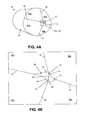
FIG. 4A is a perspective view of a tip of a cutting tool according to an aspect of the present invention taken at a different angle from the perspective view ofFIG. 3A , andFIG. 4B is an enlarged view of a portion of the tip ofFIG. 4A ; and -
FIGS. 5A-5D show steps in the manufacture of a cutting tool according to an aspect of the present invention. - A
rotary cutting tool 21 according to an aspect of the present invention is shown inFIGS. 1A and 1 B . Thetool 21 comprises a generallycylindrical body 23. Ordinarily, thebody 23 is circularly cylindrical and has a diameter of between 3-6 mm, however, the body need not be circularly cylindrical and may be larger or smaller than 3-6 mm. Thebody 23 will ordinarily have a length of about 40-60 mm, most preferably about 50 mm. Thebody 23 may, for example, by generally square, and may increase or decrease in width or diameter over some or all of its length. - The
tool 21 includes at least four substantiallyflat surfaces 25a-25d that each form an angle with a longitudinal axis A of the body. - The
tool 21 further comprises acutting tip 27 centered on the longitudinal axis A. As seen inFIGS. 2A-4B , the at least foursurfaces 25a-25d intersect with thetip 27. Thetip 27 defines at least twocutting edges tool 21 is intended to rotate in the direction D shown inFIGS. 1 B and2C . Details of thetip 27 are shown in perspective inFIGS. 3B and4B . - The
tip 27 includes a surface having a non-zero area, i.e. larger than a point. Ordinarily, thetip 27 comprises at least twosurface portions end 47 of thetip 27 and defining the at least twocutting edges surface portions - Ordinarily, at least parts of the at least two
cutting edges FIG. 2A . A presently preferred radius is 0.152 mm ± 0.005 mm. The at least twocutting edges body 23. When thetip 27 is viewed inFIG. 2B at 90° to the view ofFIG. 2A , thesurface portions surface portions FIG. 2B . - The at least two
cutting edges FIGS. 2B-2C , thecutting edges -
Rake surface portions cutting edge cutting edges tip 27 can be shaped so that it has relatively large wedge angles at the cutting edges 29 and 31 and negative axial and radial rake angles, which can result in a stronger, longer-lasting tool.Clearance surface portions surface portions rake surface portions - As seen in FlG. 2C, the at least two cutting
edges respective surface portions - Of the at least four
surfaces 25a-25d, at least twonon-consecutive ones non-consecutive ones surfaces surface portions tip 27, flutes that can facilitate removal of chips formed when machining a workpiece. Thesurfaces clearance surface portions surface portions - As seen in
FIG. 1 B , the at least foursurfaces 25a-25d are ordinarily formed so that, when thetool 21 is viewed along the longitudinal axis A, thesurfaces body 23 than thesurfaces surfaces surfaces FIG. 1 B . The longitudinal intersections of thesurfaces 25a-25d definecorners 45 that ordinarily all extend the same distance along the axis A from theend 47 of thetip 27. A presently axial distance of the ends of thecorners 45 from theend 47 of thetip 27 is 7.95 mm. - A method of making a
rotary cutting tool 21 according to an aspect of the present invention is seen inFIGS. 5A-5D . Usually starting from a cylindrical blank 23b as seen inFIG. 5A , an end of the blank 23b can be formed into acone 23c as seen inFIG. 5B to facilitate subsequent grinding of thesurfaces 25a-25b. Thesurfaces 25a-25d are formed on thecylindrical body 23 so that each of the surfaces forms an angle with the longitudinal axis A of the body.FIG. 5C shows theflat surface 25b (or 25d) being formed first, followed by theflat surface 25a (or 25c) being formed inFIG. 5D , however, the order of formation of the surfaces can be reversed. Thesurfaces 25a-25d are typically formed by grinding, however, they may be formed by other suitable techniques, such as pressing and sintering. When thesurfaces 25a-25d are formed, they ordinarily extend to theend 47 of thebody 23 as seen inFIG. 5D . Thesurfaces 25a-25d can meet at a point but, more typically, they meet at a small area remaining from the original top of thecone 23c or blank 23b, which can make forming of thetip 27 easier as less material may have to be removed when forming the tip. - After the
surfaces 25a-25d are formed, the cuttingtip 27 as seen, for example, inFIGS. 2A-2C ,3B , and4B , centered on the longitudinal axis A, is formed so that the at least four surfaces intersect with the tip. Thetip 27 defines at least two cuttingedges tip 27 is ordinarily formed by grinding, ordinarily by a five-axis grinding operation, however, the tip may be made by other means, such as by pressing and sintering. Thetip 27 is formed to define at least twosurface portions surface portions tip 27 at theend 47 of the body and define the at least two cutting edges. Thetip 27 can be formed so that at least parts of the at least two cuttingedges body 23. - In the present application, the use of terms such as "including" is open-ended and is intended to have the same meaning as terms such as "comprising" and not preclude the presence of other structure, material, or acts. Similarly, though the use of terms such as "can" or "may" is intended to be open-ended and to reflect that structure, material, or acts are not necessary, the failure to use such terms is not intended to reflect that structure, material, or acts are essential. To the extent that structure, material, or acts are presently considered to be essential, they are identified as such.
- While this invention has been illustrated and described in accordance with a preferred embodiment, it is recognized that variations and changes may be made therein without departing from the invention as set forth in the claims.
Claims (15)
- A rotary cutting tool (21), comprising:a generally cylindrical body (23),at least four substantially flat surfaces (25a-25d) that each form an angle with a longitudinal axis (A) of the body (23), anda cutting tip (27) centered on the longitudinal axis (A), the at least four flat surfaces (25a-25b) intersecting with the tip (27),characterized in that the tip (27) defines at least two cutting edges (29, 31) and in that at least parts of the at least two cutting edges (29,31) are curved.
- The rotary cutting tool (21) as set forth in claim 1, wherein the tip (27) includes a surface (33, 35) having a non-zero area.
- The rotary cutting tool (21) as set forth in any of claims 1-2, wherein the tip (27) comprises an at least partially convex surface (33, 35).
- The rotary cutting tool (21) as set forth in any of claims 1-3, wherein the tip (27) comprises at least two surface portions (33, 35), the at least two surface portions (33, 35) meeting at a forward-most end (47) of the tip (27) and defining the at least two cutting edges (29, 31).
- The rotary cutting tool (21) as set forth in any of claims 1-4, wherein at least parts of the at least two cutting edges (29, 31) are radiused.
- The rotary cutting tool (21) as set forth in any of claims 1-5, wherein the at least two cutting edges (29, 31) meet at the longitudinal axis (A) of the body (23).
- The rotary cutting tool (21) as set forth in any of claims 1-6, wherein the at least two cutting edges (29, 31) define at least one of a radially negative rake angle and an axially negative rake angle.
- The rotary cutting tool (21) as set forth in any of claims 1-7, wherein the at least two cutting edges (29, 31) are rotationally symmetrical and/or identical on opposite sides of the longitudinal axis (A).
- The rotary cutting tool (21) as set forth in any of claims 1-8, wherein at least two non-consecutive ones (25b, 25d) of the at least four flat surfaces (25a-25b) form smaller angles with the longitudinal axis (A) than at least two other non-consecutive ones (25a, 25c) of the at least four flat surfaces (25a-25b).
- The rotary cutting tool (21) as set forth in any of claims 1-9, wherein a width of the body (23) is between 3 and 6 mm.
- The rotary cutting tool (21) as set forth in any of claims 1-10, wherein the body (23) is circularly cylindrical.
- A method of making a rotary cutting tool (21), comprising:forming on a cylindrical body (23) at least four substantially flat surfaces (25a-25d) that each form an angle with a longitudinal axis (A) of the body (23), andforming a cutting tip (27) centered on the longitudinal axis (A), the at least four flat surfaces (25a-25b) intersecting with the tip (27),characterized in that the tip (27) defines at least two, curved cutting edges (29, 31).
- The method as set forth in claim 12, wherein the at least four substantially flat surfaces (25a-25d) are first formed and extend to an end of the body (23), and the tip (27) is thereafter formed by shaping portions of the four substantially flat surfaces (25a-25d) at the end of the body (23).
- The method as set forth in any of claims 12-13, wherein the tip (27) is formed to define at least two surface portions (33, 35), the at least two surface portions (33, 35) meeting at a forward-most end (47) of the tip (27) and defining the at least two cutting edges (29, 31).
- The method as set forth in any of claims 12-14, wherein the tip (27) is formed so that at least parts of the at least two cutting edges (29, 31) are radiused.
Priority Applications (1)
| Application Number | Priority Date | Filing Date | Title |
|---|---|---|---|
| EP12162051.2A EP2644302B1 (en) | 2012-03-29 | 2012-03-29 | Rotary cutting tool and method of making a rotary cutting tool |
Applications Claiming Priority (1)
| Application Number | Priority Date | Filing Date | Title |
|---|---|---|---|
| EP12162051.2A EP2644302B1 (en) | 2012-03-29 | 2012-03-29 | Rotary cutting tool and method of making a rotary cutting tool |
Publications (2)
| Publication Number | Publication Date |
|---|---|
| EP2644302A1 true EP2644302A1 (en) | 2013-10-02 |
| EP2644302B1 EP2644302B1 (en) | 2017-12-27 |
Family
ID=45954432
Family Applications (1)
| Application Number | Title | Priority Date | Filing Date |
|---|---|---|---|
| EP12162051.2A Not-in-force EP2644302B1 (en) | 2012-03-29 | 2012-03-29 | Rotary cutting tool and method of making a rotary cutting tool |
Country Status (1)
| Country | Link |
|---|---|
| EP (1) | EP2644302B1 (en) |
Citations (3)
| Publication number | Priority date | Publication date | Assignee | Title |
|---|---|---|---|---|
| US4448120A (en) | 1981-03-04 | 1984-05-15 | Richardson William A | Calligraphic apparatus and method and engraving tool for use in connection therewith |
| US20030059263A1 (en) * | 2001-09-27 | 2003-03-27 | Zen Wu Zheng Sun Tool Co. Ltd. | Rotary engraving tool |
| US8021085B1 (en) | 2007-02-23 | 2011-09-20 | Lance Nelson | Engraving tool with a very strong cutter tip to reduce breakage |
Family Cites Families (1)
| Publication number | Priority date | Publication date | Assignee | Title |
|---|---|---|---|---|
| US938434A (en) * | 1906-07-17 | 1909-10-26 | Lanston Monotype Machine Co | Cutter for punch-cutting machines. |
-
2012
- 2012-03-29 EP EP12162051.2A patent/EP2644302B1/en not_active Not-in-force
Patent Citations (3)
| Publication number | Priority date | Publication date | Assignee | Title |
|---|---|---|---|---|
| US4448120A (en) | 1981-03-04 | 1984-05-15 | Richardson William A | Calligraphic apparatus and method and engraving tool for use in connection therewith |
| US20030059263A1 (en) * | 2001-09-27 | 2003-03-27 | Zen Wu Zheng Sun Tool Co. Ltd. | Rotary engraving tool |
| US8021085B1 (en) | 2007-02-23 | 2011-09-20 | Lance Nelson | Engraving tool with a very strong cutter tip to reduce breakage |
Also Published As
| Publication number | Publication date |
|---|---|
| EP2644302B1 (en) | 2017-12-27 |
Similar Documents
| Publication | Publication Date | Title |
|---|---|---|
| CA2578787C (en) | Helical flute end mill with multi-section cutting edge | |
| JP5651605B2 (en) | Rotary cutting tool with chip breaker pattern | |
| JP6531883B1 (en) | Cutting insert and indexable cutting tool | |
| EP2869957B1 (en) | Rotary cutting tool and reversible cutting insert therefor | |
| CN102046314B (en) | Cutting inserts with wiper edges | |
| JP5848063B2 (en) | Turning inserts, turning tools and equipment | |
| JP6384385B2 (en) | Roughing end mill | |
| JP2018534159A (en) | Turning insert and method | |
| CN104781026A (en) | Corner radius end mill | |
| CN104837585A (en) | Face cutter for machining fibre-reinforced materials such as carbon-fibre-reinforced plastics (cfrp) | |
| JP7529680B2 (en) | Indexable cutting insert | |
| CN110730700B (en) | Milling methods and uses of cutting inserts | |
| JP2003531736A (en) | Milling tools | |
| JP2005224898A (en) | 3-flute ball end mill | |
| WO2006018894A1 (en) | Chamfering tool | |
| JP2011056608A (en) | Square end mill | |
| EP2644302B1 (en) | Rotary cutting tool and method of making a rotary cutting tool | |
| TWI415701B (en) | Printed board for printing substrates | |
| JP4206778B2 (en) | Center drill | |
| JP6930404B2 (en) | End mill | |
| JP6410220B1 (en) | End mill | |
| JP2006239830A (en) | Insert detachable end mill and insert | |
| JP5515327B2 (en) | End mill | |
| US7337523B1 (en) | Methods and apparatus for an annular core cutter | |
| JP5678431B2 (en) | Exchangeable grooving tool and peripheral grooving method |
Legal Events
| Date | Code | Title | Description |
|---|---|---|---|
| PUAI | Public reference made under article 153(3) epc to a published international application that has entered the european phase |
Free format text: ORIGINAL CODE: 0009012 |
|
| 17P | Request for examination filed |
Effective date: 20120329 |
|
| AK | Designated contracting states |
Kind code of ref document: A1 Designated state(s): AL AT BE BG CH CY CZ DE DK EE ES FI FR GB GR HR HU IE IS IT LI LT LU LV MC MK MT NL NO PL PT RO RS SE SI SK SM TR |
|
| AX | Request for extension of the european patent |
Extension state: BA ME |
|
| RBV | Designated contracting states (corrected) |
Designated state(s): AL AT BE BG CH CY CZ DE DK EE ES FI FR GB GR HR HU IE IS IT LI LT LU LV MC MK MT NL NO PL PT RO RS SE SI SK SM TR |
|
| 17Q | First examination report despatched |
Effective date: 20150421 |
|
| GRAP | Despatch of communication of intention to grant a patent |
Free format text: ORIGINAL CODE: EPIDOSNIGR1 |
|
| INTG | Intention to grant announced |
Effective date: 20170822 |
|
| GRAA | (expected) grant |
Free format text: ORIGINAL CODE: 0009210 |
|
| GRAS | Grant fee paid |
Free format text: ORIGINAL CODE: EPIDOSNIGR3 |
|
| AK | Designated contracting states |
Kind code of ref document: B1 Designated state(s): AL AT BE BG CH CY CZ DE DK EE ES FI FR GB GR HR HU IE IS IT LI LT LU LV MC MK MT NL NO PL PT RO RS SE SI SK SM TR |
|
| REG | Reference to a national code |
Ref country code: GB Ref legal event code: FG4D |
|
| REG | Reference to a national code |
Ref country code: CH Ref legal event code: EP |
|
| REG | Reference to a national code |
Ref country code: AT Ref legal event code: REF Ref document number: 957880 Country of ref document: AT Kind code of ref document: T Effective date: 20180115 |
|
| REG | Reference to a national code |
Ref country code: IE Ref legal event code: FG4D |
|
| REG | Reference to a national code |
Ref country code: DE Ref legal event code: R096 Ref document number: 602012041277 Country of ref document: DE |
|
| PG25 | Lapsed in a contracting state [announced via postgrant information from national office to epo] |
Ref country code: FI Free format text: LAPSE BECAUSE OF FAILURE TO SUBMIT A TRANSLATION OF THE DESCRIPTION OR TO PAY THE FEE WITHIN THE PRESCRIBED TIME-LIMIT Effective date: 20171227 Ref country code: LT Free format text: LAPSE BECAUSE OF FAILURE TO SUBMIT A TRANSLATION OF THE DESCRIPTION OR TO PAY THE FEE WITHIN THE PRESCRIBED TIME-LIMIT Effective date: 20171227 Ref country code: NO Free format text: LAPSE BECAUSE OF FAILURE TO SUBMIT A TRANSLATION OF THE DESCRIPTION OR TO PAY THE FEE WITHIN THE PRESCRIBED TIME-LIMIT Effective date: 20180327 |
|
| REG | Reference to a national code |
Ref country code: LT Ref legal event code: MG4D |
|
| REG | Reference to a national code |
Ref country code: AT Ref legal event code: MK05 Ref document number: 957880 Country of ref document: AT Kind code of ref document: T Effective date: 20171227 |
|
| PG25 | Lapsed in a contracting state [announced via postgrant information from national office to epo] |
Ref country code: BG Free format text: LAPSE BECAUSE OF FAILURE TO SUBMIT A TRANSLATION OF THE DESCRIPTION OR TO PAY THE FEE WITHIN THE PRESCRIBED TIME-LIMIT Effective date: 20180327 Ref country code: RS Free format text: LAPSE BECAUSE OF FAILURE TO SUBMIT A TRANSLATION OF THE DESCRIPTION OR TO PAY THE FEE WITHIN THE PRESCRIBED TIME-LIMIT Effective date: 20171227 Ref country code: HR Free format text: LAPSE BECAUSE OF FAILURE TO SUBMIT A TRANSLATION OF THE DESCRIPTION OR TO PAY THE FEE WITHIN THE PRESCRIBED TIME-LIMIT Effective date: 20171227 Ref country code: LV Free format text: LAPSE BECAUSE OF FAILURE TO SUBMIT A TRANSLATION OF THE DESCRIPTION OR TO PAY THE FEE WITHIN THE PRESCRIBED TIME-LIMIT Effective date: 20171227 Ref country code: GR Free format text: LAPSE BECAUSE OF FAILURE TO SUBMIT A TRANSLATION OF THE DESCRIPTION OR TO PAY THE FEE WITHIN THE PRESCRIBED TIME-LIMIT Effective date: 20180328 |
|
| PG25 | Lapsed in a contracting state [announced via postgrant information from national office to epo] |
Ref country code: EE Free format text: LAPSE BECAUSE OF FAILURE TO SUBMIT A TRANSLATION OF THE DESCRIPTION OR TO PAY THE FEE WITHIN THE PRESCRIBED TIME-LIMIT Effective date: 20171227 Ref country code: SK Free format text: LAPSE BECAUSE OF FAILURE TO SUBMIT A TRANSLATION OF THE DESCRIPTION OR TO PAY THE FEE WITHIN THE PRESCRIBED TIME-LIMIT Effective date: 20171227 Ref country code: CY Free format text: LAPSE BECAUSE OF FAILURE TO SUBMIT A TRANSLATION OF THE DESCRIPTION OR TO PAY THE FEE WITHIN THE PRESCRIBED TIME-LIMIT Effective date: 20171227 Ref country code: ES Free format text: LAPSE BECAUSE OF FAILURE TO SUBMIT A TRANSLATION OF THE DESCRIPTION OR TO PAY THE FEE WITHIN THE PRESCRIBED TIME-LIMIT Effective date: 20171227 Ref country code: CZ Free format text: LAPSE BECAUSE OF FAILURE TO SUBMIT A TRANSLATION OF THE DESCRIPTION OR TO PAY THE FEE WITHIN THE PRESCRIBED TIME-LIMIT Effective date: 20171227 |
|
| REG | Reference to a national code |
Ref country code: NL Ref legal event code: MP Effective date: 20171227 |
|
| PG25 | Lapsed in a contracting state [announced via postgrant information from national office to epo] |
Ref country code: AT Free format text: LAPSE BECAUSE OF FAILURE TO SUBMIT A TRANSLATION OF THE DESCRIPTION OR TO PAY THE FEE WITHIN THE PRESCRIBED TIME-LIMIT Effective date: 20171227 Ref country code: IS Free format text: LAPSE BECAUSE OF FAILURE TO SUBMIT A TRANSLATION OF THE DESCRIPTION OR TO PAY THE FEE WITHIN THE PRESCRIBED TIME-LIMIT Effective date: 20180427 Ref country code: IT Free format text: LAPSE BECAUSE OF FAILURE TO SUBMIT A TRANSLATION OF THE DESCRIPTION OR TO PAY THE FEE WITHIN THE PRESCRIBED TIME-LIMIT Effective date: 20171227 Ref country code: PL Free format text: LAPSE BECAUSE OF FAILURE TO SUBMIT A TRANSLATION OF THE DESCRIPTION OR TO PAY THE FEE WITHIN THE PRESCRIBED TIME-LIMIT Effective date: 20171227 Ref country code: SM Free format text: LAPSE BECAUSE OF FAILURE TO SUBMIT A TRANSLATION OF THE DESCRIPTION OR TO PAY THE FEE WITHIN THE PRESCRIBED TIME-LIMIT Effective date: 20171227 Ref country code: RO Free format text: LAPSE BECAUSE OF FAILURE TO SUBMIT A TRANSLATION OF THE DESCRIPTION OR TO PAY THE FEE WITHIN THE PRESCRIBED TIME-LIMIT Effective date: 20171227 |
|
| PG25 | Lapsed in a contracting state [announced via postgrant information from national office to epo] |
Ref country code: NL Free format text: LAPSE BECAUSE OF FAILURE TO SUBMIT A TRANSLATION OF THE DESCRIPTION OR TO PAY THE FEE WITHIN THE PRESCRIBED TIME-LIMIT Effective date: 20171227 |
|
| REG | Reference to a national code |
Ref country code: DE Ref legal event code: R097 Ref document number: 602012041277 Country of ref document: DE |
|
| REG | Reference to a national code |
Ref country code: DE Ref legal event code: R119 Ref document number: 602012041277 Country of ref document: DE |
|
| REG | Reference to a national code |
Ref country code: CH Ref legal event code: PL |
|
| PLBE | No opposition filed within time limit |
Free format text: ORIGINAL CODE: 0009261 |
|
| STAA | Information on the status of an ep patent application or granted ep patent |
Free format text: STATUS: NO OPPOSITION FILED WITHIN TIME LIMIT |
|
| GBPC | Gb: european patent ceased through non-payment of renewal fee |
Effective date: 20180329 |
|
| PG25 | Lapsed in a contracting state [announced via postgrant information from national office to epo] |
Ref country code: MC Free format text: LAPSE BECAUSE OF FAILURE TO SUBMIT A TRANSLATION OF THE DESCRIPTION OR TO PAY THE FEE WITHIN THE PRESCRIBED TIME-LIMIT Effective date: 20171227 Ref country code: DK Free format text: LAPSE BECAUSE OF FAILURE TO SUBMIT A TRANSLATION OF THE DESCRIPTION OR TO PAY THE FEE WITHIN THE PRESCRIBED TIME-LIMIT Effective date: 20171227 |
|
| 26N | No opposition filed |
Effective date: 20180928 |
|
| REG | Reference to a national code |
Ref country code: BE Ref legal event code: MM Effective date: 20180331 |
|
| REG | Reference to a national code |
Ref country code: IE Ref legal event code: MM4A |
|
| PG25 | Lapsed in a contracting state [announced via postgrant information from national office to epo] |
Ref country code: LU Free format text: LAPSE BECAUSE OF NON-PAYMENT OF DUE FEES Effective date: 20180329 |
|
| PG25 | Lapsed in a contracting state [announced via postgrant information from national office to epo] |
Ref country code: DE Free format text: LAPSE BECAUSE OF NON-PAYMENT OF DUE FEES Effective date: 20181002 Ref country code: IE Free format text: LAPSE BECAUSE OF NON-PAYMENT OF DUE FEES Effective date: 20180329 |
|
| PG25 | Lapsed in a contracting state [announced via postgrant information from national office to epo] |
Ref country code: SI Free format text: LAPSE BECAUSE OF FAILURE TO SUBMIT A TRANSLATION OF THE DESCRIPTION OR TO PAY THE FEE WITHIN THE PRESCRIBED TIME-LIMIT Effective date: 20171227 Ref country code: BE Free format text: LAPSE BECAUSE OF NON-PAYMENT OF DUE FEES Effective date: 20180331 Ref country code: CH Free format text: LAPSE BECAUSE OF NON-PAYMENT OF DUE FEES Effective date: 20180331 Ref country code: LI Free format text: LAPSE BECAUSE OF NON-PAYMENT OF DUE FEES Effective date: 20180331 Ref country code: GB Free format text: LAPSE BECAUSE OF NON-PAYMENT OF DUE FEES Effective date: 20180329 |
|
| PG25 | Lapsed in a contracting state [announced via postgrant information from national office to epo] |
Ref country code: FR Free format text: LAPSE BECAUSE OF NON-PAYMENT OF DUE FEES Effective date: 20180331 |
|
| PG25 | Lapsed in a contracting state [announced via postgrant information from national office to epo] |
Ref country code: MT Free format text: LAPSE BECAUSE OF NON-PAYMENT OF DUE FEES Effective date: 20180329 |
|
| PG25 | Lapsed in a contracting state [announced via postgrant information from national office to epo] |
Ref country code: TR Free format text: LAPSE BECAUSE OF FAILURE TO SUBMIT A TRANSLATION OF THE DESCRIPTION OR TO PAY THE FEE WITHIN THE PRESCRIBED TIME-LIMIT Effective date: 20171227 |
|
| PG25 | Lapsed in a contracting state [announced via postgrant information from national office to epo] |
Ref country code: PT Free format text: LAPSE BECAUSE OF FAILURE TO SUBMIT A TRANSLATION OF THE DESCRIPTION OR TO PAY THE FEE WITHIN THE PRESCRIBED TIME-LIMIT Effective date: 20171227 Ref country code: HU Free format text: LAPSE BECAUSE OF FAILURE TO SUBMIT A TRANSLATION OF THE DESCRIPTION OR TO PAY THE FEE WITHIN THE PRESCRIBED TIME-LIMIT; INVALID AB INITIO Effective date: 20120329 |
|
| PG25 | Lapsed in a contracting state [announced via postgrant information from national office to epo] |
Ref country code: MK Free format text: LAPSE BECAUSE OF NON-PAYMENT OF DUE FEES Effective date: 20171227 Ref country code: SE Free format text: LAPSE BECAUSE OF FAILURE TO SUBMIT A TRANSLATION OF THE DESCRIPTION OR TO PAY THE FEE WITHIN THE PRESCRIBED TIME-LIMIT Effective date: 20171227 |
|
| PG25 | Lapsed in a contracting state [announced via postgrant information from national office to epo] |
Ref country code: AL Free format text: LAPSE BECAUSE OF FAILURE TO SUBMIT A TRANSLATION OF THE DESCRIPTION OR TO PAY THE FEE WITHIN THE PRESCRIBED TIME-LIMIT Effective date: 20171227 |