EP2644295A1 - Roller hemming device - Google Patents
Roller hemming device Download PDFInfo
- Publication number
- EP2644295A1 EP2644295A1 EP20100859903 EP10859903A EP2644295A1 EP 2644295 A1 EP2644295 A1 EP 2644295A1 EP 20100859903 EP20100859903 EP 20100859903 EP 10859903 A EP10859903 A EP 10859903A EP 2644295 A1 EP2644295 A1 EP 2644295A1
- Authority
- EP
- European Patent Office
- Prior art keywords
- roller
- work
- bending roller
- final
- final bending
- Prior art date
- Legal status (The legal status is an assumption and is not a legal conclusion. Google has not performed a legal analysis and makes no representation as to the accuracy of the status listed.)
- Granted
Links
- 238000009957 hemming Methods 0.000 title claims abstract description 64
- 238000005452 bending Methods 0.000 claims abstract description 218
- 238000012423 maintenance Methods 0.000 abstract description 6
- 230000002787 reinforcement Effects 0.000 description 16
- 230000002452 interceptive effect Effects 0.000 description 6
- 238000005096 rolling process Methods 0.000 description 2
- 230000001154 acute effect Effects 0.000 description 1
- 230000000694 effects Effects 0.000 description 1
- 238000004519 manufacturing process Methods 0.000 description 1
Images




Classifications
-
- B—PERFORMING OPERATIONS; TRANSPORTING
- B21—MECHANICAL METAL-WORKING WITHOUT ESSENTIALLY REMOVING MATERIAL; PUNCHING METAL
- B21D—WORKING OR PROCESSING OF SHEET METAL OR METAL TUBES, RODS OR PROFILES WITHOUT ESSENTIALLY REMOVING MATERIAL; PUNCHING METAL
- B21D39/00—Application of procedures in order to connect objects or parts, e.g. coating with sheet metal otherwise than by plating; Tube expanders
- B21D39/02—Application of procedures in order to connect objects or parts, e.g. coating with sheet metal otherwise than by plating; Tube expanders of sheet metal by folding, e.g. connecting edges of a sheet to form a cylinder
- B21D39/021—Application of procedures in order to connect objects or parts, e.g. coating with sheet metal otherwise than by plating; Tube expanders of sheet metal by folding, e.g. connecting edges of a sheet to form a cylinder for panels, e.g. vehicle doors
- B21D39/023—Application of procedures in order to connect objects or parts, e.g. coating with sheet metal otherwise than by plating; Tube expanders of sheet metal by folding, e.g. connecting edges of a sheet to form a cylinder for panels, e.g. vehicle doors using rollers
-
- B—PERFORMING OPERATIONS; TRANSPORTING
- B21—MECHANICAL METAL-WORKING WITHOUT ESSENTIALLY REMOVING MATERIAL; PUNCHING METAL
- B21D—WORKING OR PROCESSING OF SHEET METAL OR METAL TUBES, RODS OR PROFILES WITHOUT ESSENTIALLY REMOVING MATERIAL; PUNCHING METAL
- B21D19/00—Flanging or other edge treatment, e.g. of tubes
- B21D19/02—Flanging or other edge treatment, e.g. of tubes by continuously-acting tools moving along the edge
- B21D19/04—Flanging or other edge treatment, e.g. of tubes by continuously-acting tools moving along the edge shaped as rollers
- B21D19/043—Flanging or other edge treatment, e.g. of tubes by continuously-acting tools moving along the edge shaped as rollers for flanging edges of plates
Definitions
- the present invention relates to a roller hemming device for hemming a work by use of a roller.
- a roller hemming device is widely known that is configured to perform bending (preliminary bending) of a standing flange of a work such as a door subassembly of a car at a predetermined angle by use of a roller, and then to perform bending (final bending) of the flange at a final angle by use of the roller.
- a work W as a subject to be hemmed by the roller hemming device is a door subassembly.
- the work W includes a door panel W10 having a plurality of plates, and a door frame W20 projecting upward from the door panel W10 to configure a window frame.
- the roller hemming device hems the beltline (the top end of the door panel W10) of the work W, the roller hemming device located in the window frame may interfere with the door frame W20. Therefore, it is difficult to roll a roller along the beltline of the work W.
- the door panel W10 includes an outer panel W11 which has a standing flange (the right end part of the outer panel W11 in Fig. 6 ) and which is placed on a bottom die B, an outer reinforcement W12 which is arranged on the outer panel W11 and to the left of the flange, an inner reinforcement W13 which is arranged at a predetermined distance above the outer reinforcement W12, and an inner panel W14 which is placed on the inner reinforcement W13. Since the beltline of the work W has the narrow clearance between the outer panel W11 and the outer reinforcement W12, and the inner reinforcement W13 and the inner panel W14, the roller hemming device interferes with the work W. Therefore, it is difficult for the roller hemming device to hem the beltline of the work W. Note that Fig. 6 is an end view taken along the line A-A of Fig. 5 .
- the objective of the present invention is to provide a roller hemming device capable of hemming even when a subject to be hemmed is located in a narrow place, and reducing maintenance frequency.
- the first embodiment of the present invention is a roller hemming device, which includes a preliminary bending roller for performing preliminary bending of a work, a final bending roller for performing final bending of the work, and an arm for setting attitudes of the preliminary bending roller and the final bending roller at desired positions and angles, in which the preliminary bending roller has an axis inclined with respect to a horizontal direction, and is arranged at such a position not to come in contact with the work during the final bending, in which the final bending roller is formed in a circular truncated cone, has an axis which is inclined with respect to the horizontal direction so that, during the final bending, a large diameter surface of the final bending roller faces toward the work and a processing surface of the final bending roller is horizontally positioned, and is arranged at such a position not to come in contact with the work during the preliminary bending, and in which the preliminary bending roller and the final bending roller are arranged along a vertical direction, each having a processing point located in a vicinity of an axi
- the embodiment of the roller hemming device has a backup roller which rotates depending on the rotation of the final bending roller, in which the backup roller is arranged so as to come in contact with a surface of the final bending roller opposite to the processing surface of the final bending roller in a diametrical direction.
- the embodiment of the roller hemming device has a means for equalizing a processing pressure during the preliminary bending or the final bending of the work by biasing the preliminary bending roller and the final bending roller toward the work at a constant pressure and by absorbing a counterforce.
- the present invention makes it possible to perform hemming even when a subject to be hemmed is located in a narrow place, and to reduce maintenance frequency.
- the roller hemming device 1 is a device for hemming a beltline of a work W.
- the work W is a door subassembly fabricated in a step for manufacturing cars.
- the work W includes an outer panel W11 which has a standing flange (the right end part of the outer panel W11 in Fig.
- a top-bottom direction and a right-left direction in Fig. 1 are defined as a top-bottom direction and a right-left direction of th e roller hemming device 1, respectively.
- the top-bottom direction in Fig. 1 corresponds to the vertical direction.
- the roller hemming device 1 has a preliminary bending roller 10 for preliminarily bending the work W, a final bending roller 20 for finally bending the work W, a backup roller 30 which rotates depending on the rotation of the final bending roller 20, an attachment member 40 to which the rollers 10, 20, 30 are rotatably attached, an air cylinder 50 which biases the attachment member 40 at a predetermined pressure, a supporting member 60 which supports the attachment member 40 slidably and which supports the air cylinder 50, and an arm 70 which is fixed to the supporting member 60 and which is capable of setting the attitudes of the preliminary bending roller 10 and the final bending roller 20 at desired positions and angles.
- the roller hemming device 1 preliminarily bends the work W a plurality of times by rolling the preliminary bending roller 10 along the beltline of the work W via the arm 70, and then finally bends the work W by rolling the final bending roller 20 along the beltline of the work W via the arm 70, thus hemming the work W.
- the preliminary bending roller 10 is a roller for performing "preliminary bending” which means bending the flange of the outer panel W11 of the work W at a predetermined angle.
- the preliminary bending roller 10 is formed in a circular cylinder, and is rotatably attached to the bottom end part of the attachment member 40 so that the axis of the preliminary bending roller 10 forms a predetermined angle with respect to the horizontal direction.
- the preliminary bending roller 10 is arranged on the left side of the bottom end part of the attachment member 40.
- the final bending roller 20 is a roller for performing "final bending” which means bending the flange of the outer panel W11 of the work W passed through the preliminary bending at a final angle (such an angle that the flange comes in contact with the top surface of the outer reinforcement W12).
- the final bending roller 20 is rotatably attached to the middle part of the attachment member 40 in the top-bottom direction so that the axis of the final bending roller 20 forms a predetermined angle with respect to the horizontal direction.
- the final bending roller 20 is formed in a circular truncated cone, and the large diameter surface thereof faces to the right.
- the final bending roller 20 inclines so that the processing surface thereof (the bottom end of the outer circumferential surface) is horizontally positioned, and is attached to the attachment member 40.
- the final bending roller 20 is arranged on the side (right side) of the attachment member 40 opposite to the preliminary bending roller 10 in the right-left direction.
- the final bending roller 20 and the preliminary bending roller 10 are arranged at the upper side and lower side, and are attached to the right side and left side of the attachment member 40, respectively.
- the backup roller 30 comes in contact with the outer circumferential surface of the final bending roller 20, and rotates depending on the rotation of the final bending roller 20.
- the backup roller 30 is formed in substantially a circular cylinder, and is rotatably attached to the attachment member 40 so that the axis of the backup roller 30 is horizontally positioned.
- the backup roller 30 is formed so that the outer circumferential surface thereof inclines from the right edge to the middle part thereof along the outer circumferential surface of the final bending roller 20.
- the backup roller 30 is arranged so that the bottom end of the inclining part of the outer circumferential surface thereof comes in contact with the top end of the outer circumferential surface of the final bending roller 20.
- the backup roller 30 is arranged on the top of the final bending roller 20 so as to come in contact with the surface of the final bending roller 20 opposite to the processing surface thereof in a diametrical direction of the final bending roller 20.
- This makes it possible to apply a force toward the flange to the final bending roller 20 which moves out of proximity with the flange by a counterforce when the final bending roller 20 performs the final bending to the flange of the outer panel W11. Therefore, it becomes possible to prevent the final bending roller 20 from flexing at the time of hemming, and to hem the work W in a suitable thickness.
- the backup roller 30 since the backup roller 30 rotates depending on the rotation of the final bending roller 20 at the time of hemming, the backup roller 30 does not impede the rotation of the final bending roller 20.
- the backup roller 30 is arranged so that the axis thereof is horizontally positioned, but as long as the backup roller 30 can rotate depending on the rotation of the final bending roller 20, the backup roller 30 may be arranged so that the axis thereof is vertically positioned, for example.
- the attachment member 40 is a member which has the shape extended in the top-bottom direction while being bent, and to which the rollers 10, 20, 30 are rotatably attached.
- the attachment member 40 has a first bent part 41 to which the preliminary bending roller 10 is attached, a second bent part 42 to which the final bending roller 20 is attached, and a straight part 43 to which the backup roller 30 is attached.
- the first bent part 41 has the shape which is extended from the connection between the first bent part 41 and the second bent part 42 to the lower left according to the inclination angle of the preliminary bending roller 10 so as to form a predetermined angle with respect to the vertical direction.
- the preliminary bending roller 10 is attached to the left side of the extension end part of the first bent part 41, and the processing point of the preliminary bending roller 10 is located in the vicinity of the axis (the chain line C in Fig. 1 ) of the arm 70.
- the term "the axis of the arm 70" means a straight line extending, in the vertical direction, from the central part of the surface of the arm 70 coming in contact with the supporting member 60, namely, from the central part of the surface of the supporting member 60 pressed by the arm 70 at the time of hemming,.
- the second bent part 42 has the shape which is extended from the connection between the second bent part 42 and the straight part 43 to the lower right according to the inclination angle of the final bending roller 20 so as to form a predetermined angle with respect to the vertical direction.
- the extension end part of the second bent part 42 is connected with the base end part (top end part) of the first bent part 41.
- the second bent part 42 is extended so as to intersect the axis of the arm 70.
- the final bending roller 20 is attached to the right side of the second bent part 42, and the processing point of the final bending roller 20 is located in the vicinity of the axis of the arm 70.
- the straight part 43 has the shape extended straight in the top-bottom direction, and the bottom end part thereof is connected with the base end part (top end part) of the second bent part 42.
- the backup roller 30 is attached to the lower part of the straight part 43, and is arranged on the right side of the straight part 43 so as to come in contact with the final bending roller 20.
- the first bent part 41 and the second bent part 42 are extended to the lower left and the lower right, respectively, so as to intersect the axis of the arm 70.
- This makes it possible to hold the preliminary bending roller 10 and the final bending roller 20 inclined, and to locate the processing points of the preliminary bending roller 10 and the final bending roller 20 in the vicinity of the axis of the arm 70. Therefore, it is possible to prevent the flexure of the attachment member 40 caused by the moment occurring at the time of hemming according to a counterforce and a distance from the axis of the arm 70 in the horizontal direction, and to hem the work W in a suitable thickness.
- the term "the vicinity of the axis of the arm 70" means not only the area on the axis of the arm 70 but also the area around the axis of the arm 70, and means such an area that the moment occurring at the time of hemming according to a counterforce and a distance from the axis of the arm 70 in the horizontal direction is controlled to a minimum and that the roller hemming device 1 can hem the work W in a suitable thickness without the flexure of the attachment member 40.
- the air cylinder 50 is an air cylinder for biasing the attachment member 40 downward at a predetermined pressure, and acts as a means for equalizing a processing pressure at the time of hemming.
- the air cylinder 50 has a fixed part 51 attached to the supporting member 60 and a movable part 52 capable of moving with respect to the fixed part 51 in the top-bottom direction.
- the fixed part 51 supports the movable part 52, and biases the movable part 52 downward at a predetermined pressure with compressed air.
- the top end part of the fixed part 51 is fixed to the supporting member 60.
- the movable part 52 consists of a piston and the like, and is supported by the fixed part 51 so as to move in the top-bottom direction.
- the movable part 52 is arranged on the right side of the straight part 43 of the attachment member 40, and is fixed to the upper part of the straight part 43.
- the movable part 52 supported by the fixed part 51 is biased downward at a predetermined pressure by the compressed air. It follows from this that the preliminary bending roller 10 and the final bending roller 20 is biased downward at a predetermined pressure through the attachment member 40 fixed to the movable part 52. Moreover, strokes of the movable part 52 supported by the fixed part 51 absorbs a counterforce at the time of hemming. This makes it possible to perform the preliminary bending of the work W with the preliminary bending roller 10 at a uniform pressure, and to perform the final bending of the work W with the final bending roller 20 at a uniform pressure.
- the arm 70 is controlled so that each of the preliminary bending roller 10 and the final bending roller 20 arrives linearly at each of a plurality of predetermined points. Therefore, in a case where a subject to be hemmed by the roller hemming device 1 is not a straight part such as the beltline of the work W in the present embodiment but a curved part, a contact area between the preliminary bending roller 10 and the subject, and a contact area between the final bending roller 20 and the subject vary.
- the preliminary bending roller 10 and the final bending roller 20 are biased downward at a constant pressure while the air cylinder 50 absorbs a counterforce, thus enabling to equalize the processing pressure, and to perform hemming uniformly without variation in the processing pressure even in a case where the subject to be hemmed is a curved part.
- an air cylinder is adopted as the means for equalizing the processing pressure, but the present invention is not limited to this.
- An oil hydraulic cylinder, a spring or the like may be adopted as the means.
- the supporting member 60 has a vertical part 61 extending in the top-bottom direction and a horizontal part 62 extending in the right-left direction, and is formed in substantially a L-shape in which the top end part of the vertical part 61 and the left end part of the horizontal part 62 are joined.
- the vertical part 61 is arranged to the left of the straight part 43 of the attachment member 40, and supports the upper part of the straight part 43 slidably.
- the slide structure is not limited to the present embodiment, and an existing linear guide and the like may be adopted.
- the horizontal part 62 is arranged on the top of the air cylinder 50, and supports the air cylinder 50. Specifically, the bottom end part of the horizontal part 62 and the top end part of the fixed part 51 of the air cylinder 50 are fixed. Moreover, the top end part of the horizontal part 62 is fixed to the extremity (the bottom end part) of the arm 70.
- the vertical part 61 supports the attachment member 40 slidably, and the horizontal part 62 supports the air cylinder 50.
- This enables the attachment member 40 fixed to the movable part 52 to move not in the right-left direction but only in the top-bottom direction depending on the movement of the movable part 52 of the air cylinder 50.
- the arm 70 is a robotic arm which can be set at desired position and angle, and is attached to the top end part of the horizontal part 62 of the supporting member 60.
- the arm 70 can set the attitudes of the preliminary bending roller 10 and the final bending roller 20 at desired positions and angles through the supporting member 60 and the attachment member 40.
- the arm 70 causes the preliminary bending roller 10 or the final bending roller 20 to press the flange of the outer panel W11 of the work W, and to roll along the beltline of the work W.
- the work W is hemmed.
- the preliminary bending of the work W is performed.
- the lower part of the preliminary bending roller 10 is moved into the clearance between the outer panel W11 and the outer reinforcement W12, and the inner reinforcement W13 and the inner panel W14 in the beltline of the work W by the arm 70.
- the preliminary bending roller 10 presses the flange of the outer panel W11 of the work W, and bends the flange at the angle of the processing surface of the preliminary bending roller 10.
- the preliminary bending roller 10 rolls along the beltline of the work W while pressing the flange, and thereby performs the preliminary bending of the whole flange.
- the attachment member 40 since the attachment member 40 is bent, and the first bent part 41 of the attachment member 40 has the shape which is extended toward the flange in the lower left direction during the preliminary bending of the flange, the attachment member 40 holds the preliminary bending roller 10 inclined. This makes it possible to move the preliminary bending roller 10 into the narrow clearance formed in the beltline of the work W without the preliminary bending roller 10 and the first bent part 41 interfering with the work W, and to excellently perform the preliminary bending of the flange. Additionally, this makes it possible to shorten the length of the preliminary bending roller 10 in the axial direction thereof.
- the second bent part 42 of the attachment member 40 has the shape which is extended to the lower right so as to move out of proximity with the flange during the preliminary bending of the flange, the second bent part 42 supports the final bending roller 20 on the opposite side to the preliminary bending roller 10 in the right-left direction. This makes it possible to excellently perform the preliminary bending of the flange without the final bending roller 20 and the second bent part 42 interfering with the work W.
- the preliminary bending roller 10 performs the preliminary bending of the work W a plurality of times. In the present embodiment, the preliminary bending of the work W is performed twice.
- the arm 70 set the preliminary bending roller 10 at such an angle that an angle formed between the processing surface of the preliminary bending roller 10 and the horizontal plane is ⁇ 1. Then, by performing the preliminary bending of the work W as mentioned above, the work W is formed in which an angle (hereinafter called "a preliminary bending angle") formed between the flange and the other part of the outer panel W11 is ⁇ 1. As shown in Fig. 3(b) , in the second preliminary bending, the arm 70 set the preliminary bending roller 10 at such an angle that an angle formed between the processing surface of the preliminary bending roller 10 and the horizontal plane is ⁇ 2 ( ⁇ 2 ⁇ ⁇ 1).
- Fig. 3 illustrates only the outer panel W11 of the work W and the preliminary bending roller 10 of the roller hemming device 1.
- the final bending roller 20 and the preliminary bending roller 10 are arranged at the upper side and lower side respectively, and the processing points of the final bending roller 20 and the preliminary bending roller 10 are arranged in the vicinity of the axis of the arm 70.
- the inclination of the preliminary bending roller 10 makes it possible to select the preliminary bending angle from a wider range (e.g. 20 to 90 degrees). Therefore, it becomes possible to perform the preliminary bending of the work W a plurality of times as mentioned above, and, compared with the case where the preliminary bending is performed once or the case only the final bending is performed without the preliminary bending, to reduce a processing amount of the flange per time to control poor quality such as local elongation of the flange to a minimum.
- the preliminary bending roller 10 is formed in a circular cylinder, but the present invention is not limited to this. As long as the preliminary bending angle can be set at a desired value, the preliminary bending roller 10 may be formed in a circular truncated cone as with the final bending roller 20.
- the preliminary bending angle may be calculated as mentioned below. Based on an elongation rate of the flange calculated from the diameter of the preliminary bending roller 10 and a processing amount of the flange during the preliminary bending, an elongation amount of the flange during the preliminary bending is calculated, and the processing amount of the flange such that the elongation amount does not exceed a limit value based on an empirical rule is calculated. Then, the number of times of the preliminary bending is calculated from the calculated processing amount of the flange and the angle (90 degrees in the present embodiment) of the flange before being hemmed, and as a result, the preliminary bending angle is obtained.
- the final bending of the work W is performed.
- the roller hemming device 1 is in the left-right reverse attitude relative to the attitude during the preliminary bending.
- the lower part of the final bending roller 20 is moved into the clearance between the outer panel W11 and the outer reinforcement W12, and the inner reinforcement W13 and the inner panel W14 in the beltline of the work W by the arm 70.
- the final bending roller 20 presses the flange of the outer panel W11 of the work W with the processing surface thereof horizontal, and bends the flange so that the flange is horizontally positioned (so that the flange comes in contact with the top surface of the outer reinforcement W12).
- the final bending roller 20 rolls along the beltline of the work W while pressing the flange, and thereby performs the final bending of the whole flange.
- the pressure of the final bending roller 20 against the work W during the final bending is larger than the pressure of the preliminary bending roller 10 against the work W during the preliminary bending. Therefore, arranging the backup roller 30 on the top of the final bending roller 20 prevents the final bending roller 20 from flexing.
- the final bending roller 20 is formed in a circular truncated cone, and the large diameter surface thereof faces toward the work W during the final bending. Accordingly, the processing surface of the final bending roller 20, and the large diameter surface thereof form an acute angle. This makes it possible to move the final bending roller 20 into the narrow clearance formed in the beltline of the work W without the final bending roller 20 interfering with the work W, and to excellently perform the final bending of the flange. Additionally, this makes it possible to increase the outside diameter of the final bending roller 20, and thereby to control poor quality such as local elongation of the flange to a minimum and to improve the durability of the final bending roller 20.
- this makes it possible to shorten the length of the final bending roller 20 in the axial direction thereof. Therefore, it becomes possible to prevent the deformation of the attachment member 40, and to reduce the maintenance frequency of the roller hemming device 1 because the big moment does not act, at the time of hemming, on the part of the attachment member 40 to which the final bending roller 20 is attached. Moreover, since the attachment member 40 is bent, and the second bent part 42 of the attachment member 40 has the shape extended toward the flange in the lower left direction during the final bending of the flange, the attachment member 40 holds the final bending roller 20 inclined.
- the first bent part 41 of the attachment member 40 has the shape which is extended to the lower right so as to move out of proximity with the flange during the final bending of the flange, the first bent part 41 supports the preliminary bending roller 10 on the opposite side to the final bending roller 20 in the right-left direction. This makes it possible to perform the final bending of the flange without the preliminary bending roller 10 and the first bent part 41 interfering with the work W.
- the present invention is applied to a roller hemming device for hemming a subject in a narrow place such as a beltline of a door panel.
Landscapes
- Engineering & Computer Science (AREA)
- Mechanical Engineering (AREA)
- Bending Of Plates, Rods, And Pipes (AREA)
Abstract
Description
- The present invention relates to a roller hemming device for hemming a work by use of a roller.
- Conventionally, a roller hemming device is widely known that is configured to perform bending (preliminary bending) of a standing flange of a work such as a door subassembly of a car at a predetermined angle by use of a roller, and then to perform bending (final bending) of the flange at a final angle by use of the roller.
- As shown in
Fig. 5 , a work W as a subject to be hemmed by the roller hemming device is a door subassembly. The work W includes a door panel W10 having a plurality of plates, and a door frame W20 projecting upward from the door panel W10 to configure a window frame. When the roller hemming device hems the beltline (the top end of the door panel W10) of the work W, the roller hemming device located in the window frame may interfere with the door frame W20. Therefore, it is difficult to roll a roller along the beltline of the work W. - As shown in
Fig. 6 , the door panel W10 includes an outer panel W11 which has a standing flange (the right end part of the outer panel W11 inFig. 6 ) and which is placed on a bottom die B, an outer reinforcement W12 which is arranged on the outer panel W11 and to the left of the flange, an inner reinforcement W13 which is arranged at a predetermined distance above the outer reinforcement W12, and an inner panel W14 which is placed on the inner reinforcement W13. Since the beltline of the work W has the narrow clearance between the outer panel W11 and the outer reinforcement W12, and the inner reinforcement W13 and the inner panel W14, the roller hemming device interferes with the work W. Therefore, it is difficult for the roller hemming device to hem the beltline of the work W.
Note thatFig. 6 is an end view taken along the line A-A ofFig. 5 . - When the beltline of the work W as mentioned above is hemmed, in order to avoid interference with the work W, a roller hemming device having a roller with the small outside diameter and the long length in the axial direction needs to be used (for example, see
JP 2008-100272 A - However, as shown in
Fig. 7 , in aroller hemming device 100 having aroller 101, which is the roller as mentioned above, with the small outside diameter and the long length in the axial direction, since flexure occurs at the time of the hemming because of the large interval between a part of theroller 101 coming in contact with the flange of the outer panel W11 to hem the work W, and anattachment member 102 to which theroller 101 is attached, it is difficult to hem the work W to a desired thickness. Moreover, since the big moment acts on theattachment member 102 at the time of the hemming, the problem occurs that theattachment member 102 is deformed for example. As a result, the time and cost required for the maintenance of theroller hemming device 100 increase.
On the other hand, because of the small outside diameter of theroller 101, when theroller 101 sequentially bends the flange of the outer panel W11, the elongation amount of the flange partly increases. As a result, the problem occurs that the flange is formed in waves for example. -
- Patent Literature 1:
JP 2008-100272 A - The objective of the present invention is to provide a roller hemming device capable of hemming even when a subject to be hemmed is located in a narrow place, and reducing maintenance frequency.
- The first embodiment of the present invention is a roller hemming device, which includes a preliminary bending roller for performing preliminary bending of a work, a final bending roller for performing final bending of the work, and an arm for setting attitudes of the preliminary bending roller and the final bending roller at desired positions and angles, in which the preliminary bending roller has an axis inclined with respect to a horizontal direction, and is arranged at such a position not to come in contact with the work during the final bending, in which the final bending roller is formed in a circular truncated cone, has an axis which is inclined with respect to the horizontal direction so that, during the final bending, a large diameter surface of the final bending roller faces toward the work and a processing surface of the final bending roller is horizontally positioned, and is arranged at such a position not to come in contact with the work during the preliminary bending, and in which the preliminary bending roller and the final bending roller are arranged along a vertical direction, each having a processing point located in a vicinity of an axis of the arm.
- Advantageously, the embodiment of the roller hemming device has a backup roller which rotates depending on the rotation of the final bending roller, in which the backup roller is arranged so as to come in contact with a surface of the final bending roller opposite to the processing surface of the final bending roller in a diametrical direction.
- Preferably, the embodiment of the roller hemming device has a means for equalizing a processing pressure during the preliminary bending or the final bending of the work by biasing the preliminary bending roller and the final bending roller toward the work at a constant pressure and by absorbing a counterforce.
- The present invention makes it possible to perform hemming even when a subject to be hemmed is located in a narrow place, and to reduce maintenance frequency.
-
-
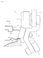
Fig. 1 illustrates a roller hemming device according to the present invention. -
Fig. 2 shows how the roller hemming device preliminarily bends a work. -
Fig. 3 shows how the work is preliminarily bended a plurality of times. -
Fig. 4 shows how the roller hemming device finally bends the work. -
Fig. 5 illustrates a door subassembly as the work. -
Fig. 6 illustrates a beltline of the work, and is an end view taken along the line A-A ofFig. 5 . -
Fig. 7 shows how a conventional roller hemming device hems the work. - With reference to
Fig. 1 , aroller hemming device 1 as an embodiment of a roller hemming device according to the present invention is described below.
Theroller hemming device 1 is a device for hemming a beltline of a work W.
The work W is a door subassembly fabricated in a step for manufacturing cars. The work W includes an outer panel W11 which has a standing flange (the right end part of the outer panel W11 inFig. 6 ) and which is placed on a bottom die B, an outer reinforcement W12 which is arranged on the outer panel W11 and to the left of the flange, an inner reinforcement W13 which is arranged at a predetermined distance above the outer reinforcement W12, and an inner panel W14 which is placed on the inner reinforcement W13 (seeFig. 6 ).
The bottom die B is a member on which the work W is placed so that the outer panel W11 comes in contact with the bottom die B.
Note that a top-bottom direction and a right-left direction inFig. 1 are defined as a top-bottom direction and a right-left direction of th eroller hemming device 1, respectively. The top-bottom direction inFig. 1 corresponds to the vertical direction. - As shown in
Fig. 1 , theroller hemming device 1 has apreliminary bending roller 10 for preliminarily bending the work W, afinal bending roller 20 for finally bending the work W, abackup roller 30 which rotates depending on the rotation of thefinal bending roller 20, anattachment member 40 to which therollers air cylinder 50 which biases theattachment member 40 at a predetermined pressure, a supportingmember 60 which supports theattachment member 40 slidably and which supports theair cylinder 50, and anarm 70 which is fixed to the supportingmember 60 and which is capable of setting the attitudes of thepreliminary bending roller 10 and thefinal bending roller 20 at desired positions and angles.
Theroller hemming device 1 preliminarily bends the work W a plurality of times by rolling thepreliminary bending roller 10 along the beltline of the work W via thearm 70, and then finally bends the work W by rolling thefinal bending roller 20 along the beltline of the work W via thearm 70, thus hemming the work W. - The
preliminary bending roller 10 is a roller for performing "preliminary bending" which means bending the flange of the outer panel W11 of the work W at a predetermined angle. Thepreliminary bending roller 10 is formed in a circular cylinder, and is rotatably attached to the bottom end part of theattachment member 40 so that the axis of thepreliminary bending roller 10 forms a predetermined angle with respect to the horizontal direction. Thepreliminary bending roller 10 is arranged on the left side of the bottom end part of theattachment member 40. - The
final bending roller 20 is a roller for performing "final bending" which means bending the flange of the outer panel W11 of the work W passed through the preliminary bending at a final angle (such an angle that the flange comes in contact with the top surface of the outer reinforcement W12). Thefinal bending roller 20 is rotatably attached to the middle part of theattachment member 40 in the top-bottom direction so that the axis of thefinal bending roller 20 forms a predetermined angle with respect to the horizontal direction. Thefinal bending roller 20 is formed in a circular truncated cone, and the large diameter surface thereof faces to the right. Specifically, thefinal bending roller 20 inclines so that the processing surface thereof (the bottom end of the outer circumferential surface) is horizontally positioned, and is attached to theattachment member 40. Thefinal bending roller 20 is arranged on the side (right side) of theattachment member 40 opposite to thepreliminary bending roller 10 in the right-left direction.
Thus, thefinal bending roller 20 and thepreliminary bending roller 10 are arranged at the upper side and lower side, and are attached to the right side and left side of theattachment member 40, respectively. - The
backup roller 30 comes in contact with the outer circumferential surface of thefinal bending roller 20, and rotates depending on the rotation of thefinal bending roller 20. Thebackup roller 30 is formed in substantially a circular cylinder, and is rotatably attached to theattachment member 40 so that the axis of thebackup roller 30 is horizontally positioned. Thebackup roller 30 is formed so that the outer circumferential surface thereof inclines from the right edge to the middle part thereof along the outer circumferential surface of thefinal bending roller 20. Thebackup roller 30 is arranged so that the bottom end of the inclining part of the outer circumferential surface thereof comes in contact with the top end of the outer circumferential surface of thefinal bending roller 20. In other words, thebackup roller 30 is arranged on the top of thefinal bending roller 20 so as to come in contact with the surface of thefinal bending roller 20 opposite to the processing surface thereof in a diametrical direction of thefinal bending roller 20.
This makes it possible to apply a force toward the flange to thefinal bending roller 20 which moves out of proximity with the flange by a counterforce when thefinal bending roller 20 performs the final bending to the flange of the outer panel W11. Therefore, it becomes possible to prevent thefinal bending roller 20 from flexing at the time of hemming, and to hem the work W in a suitable thickness. Note that since thebackup roller 30 rotates depending on the rotation of thefinal bending roller 20 at the time of hemming, thebackup roller 30 does not impede the rotation of thefinal bending roller 20.
In the present embodiment, thebackup roller 30 is arranged so that the axis thereof is horizontally positioned, but as long as thebackup roller 30 can rotate depending on the rotation of thefinal bending roller 20, thebackup roller 30 may be arranged so that the axis thereof is vertically positioned, for example. - The
attachment member 40 is a member which has the shape extended in the top-bottom direction while being bent, and to which therollers attachment member 40 has afirst bent part 41 to which thepreliminary bending roller 10 is attached, asecond bent part 42 to which thefinal bending roller 20 is attached, and astraight part 43 to which thebackup roller 30 is attached. - The first
bent part 41 has the shape which is extended from the connection between the firstbent part 41 and the secondbent part 42 to the lower left according to the inclination angle of thepreliminary bending roller 10 so as to form a predetermined angle with respect to the vertical direction. Thepreliminary bending roller 10 is attached to the left side of the extension end part of the firstbent part 41, and the processing point of thepreliminary bending roller 10 is located in the vicinity of the axis (the chain line C inFig. 1 ) of thearm 70.
As used herein, the term "the axis of thearm 70" means a straight line extending, in the vertical direction, from the central part of the surface of thearm 70 coming in contact with the supportingmember 60, namely, from the central part of the surface of the supportingmember 60 pressed by thearm 70 at the time of hemming,. - The second
bent part 42 has the shape which is extended from the connection between the secondbent part 42 and thestraight part 43 to the lower right according to the inclination angle of thefinal bending roller 20 so as to form a predetermined angle with respect to the vertical direction. The extension end part of the secondbent part 42 is connected with the base end part (top end part) of the firstbent part 41. The secondbent part 42 is extended so as to intersect the axis of thearm 70. Thefinal bending roller 20 is attached to the right side of the secondbent part 42, and the processing point of thefinal bending roller 20 is located in the vicinity of the axis of thearm 70. - The
straight part 43 has the shape extended straight in the top-bottom direction, and the bottom end part thereof is connected with the base end part (top end part) of the secondbent part 42.
Thebackup roller 30 is attached to the lower part of thestraight part 43, and is arranged on the right side of thestraight part 43 so as to come in contact with thefinal bending roller 20. - Thus, in the
attachment member 40, the firstbent part 41 and the secondbent part 42 are extended to the lower left and the lower right, respectively, so as to intersect the axis of thearm 70.
This makes it possible to hold thepreliminary bending roller 10 and thefinal bending roller 20 inclined, and to locate the processing points of thepreliminary bending roller 10 and thefinal bending roller 20 in the vicinity of the axis of thearm 70. Therefore, it is possible to prevent the flexure of theattachment member 40 caused by the moment occurring at the time of hemming according to a counterforce and a distance from the axis of thearm 70 in the horizontal direction, and to hem the work W in a suitable thickness.
As used herein, the term "the vicinity of the axis of thearm 70" means not only the area on the axis of thearm 70 but also the area around the axis of thearm 70, and means such an area that the moment occurring at the time of hemming according to a counterforce and a distance from the axis of thearm 70 in the horizontal direction is controlled to a minimum and that theroller hemming device 1 can hem the work W in a suitable thickness without the flexure of theattachment member 40. - The
air cylinder 50 is an air cylinder for biasing theattachment member 40 downward at a predetermined pressure, and acts as a means for equalizing a processing pressure at the time of hemming. Theair cylinder 50 has a fixedpart 51 attached to the supportingmember 60 and amovable part 52 capable of moving with respect to the fixedpart 51 in the top-bottom direction. - The
fixed part 51 supports themovable part 52, and biases themovable part 52 downward at a predetermined pressure with compressed air. The top end part of the fixedpart 51 is fixed to the supportingmember 60.
Themovable part 52 consists of a piston and the like, and is supported by the fixedpart 51 so as to move in the top-bottom direction. Themovable part 52 is arranged on the right side of thestraight part 43 of theattachment member 40, and is fixed to the upper part of thestraight part 43. - Thus, in the
air cylinder 50, themovable part 52 supported by the fixedpart 51 is biased downward at a predetermined pressure by the compressed air. It follows from this that thepreliminary bending roller 10 and thefinal bending roller 20 is biased downward at a predetermined pressure through theattachment member 40 fixed to themovable part 52. Moreover, strokes of themovable part 52 supported by the fixedpart 51 absorbs a counterforce at the time of hemming.
This makes it possible to perform the preliminary bending of the work W with thepreliminary bending roller 10 at a uniform pressure, and to perform the final bending of the work W with thefinal bending roller 20 at a uniform pressure.
Thearm 70 is controlled so that each of thepreliminary bending roller 10 and thefinal bending roller 20 arrives linearly at each of a plurality of predetermined points. Therefore, in a case where a subject to be hemmed by theroller hemming device 1 is not a straight part such as the beltline of the work W in the present embodiment but a curved part, a contact area between thepreliminary bending roller 10 and the subject, and a contact area between thefinal bending roller 20 and the subject vary.
However, at the time of hemming, thepreliminary bending roller 10 and thefinal bending roller 20 are biased downward at a constant pressure while theair cylinder 50 absorbs a counterforce, thus enabling to equalize the processing pressure, and to perform hemming uniformly without variation in the processing pressure even in a case where the subject to be hemmed is a curved part.
In the present embodiment, an air cylinder is adopted as the means for equalizing the processing pressure, but the present invention is not limited to this. An oil hydraulic cylinder, a spring or the like may be adopted as the means. - The supporting
member 60 has avertical part 61 extending in the top-bottom direction and ahorizontal part 62 extending in the right-left direction, and is formed in substantially a L-shape in which the top end part of thevertical part 61 and the left end part of thehorizontal part 62 are joined. - The
vertical part 61 is arranged to the left of thestraight part 43 of theattachment member 40, and supports the upper part of thestraight part 43 slidably. The slide structure is not limited to the present embodiment, and an existing linear guide and the like may be adopted. - The
horizontal part 62 is arranged on the top of theair cylinder 50, and supports theair cylinder 50. Specifically, the bottom end part of thehorizontal part 62 and the top end part of the fixedpart 51 of theair cylinder 50 are fixed.
Moreover, the top end part of thehorizontal part 62 is fixed to the extremity (the bottom end part) of thearm 70. - Thus, in the supporting
member 60, thevertical part 61 supports theattachment member 40 slidably, and thehorizontal part 62 supports theair cylinder 50.
This enables theattachment member 40 fixed to themovable part 52 to move not in the right-left direction but only in the top-bottom direction depending on the movement of themovable part 52 of theair cylinder 50. - The
arm 70 is a robotic arm which can be set at desired position and angle, and is attached to the top end part of thehorizontal part 62 of the supportingmember 60. Thearm 70 can set the attitudes of thepreliminary bending roller 10 and thefinal bending roller 20 at desired positions and angles through the supportingmember 60 and theattachment member 40. Thearm 70 causes thepreliminary bending roller 10 or thefinal bending roller 20 to press the flange of the outer panel W11 of the work W, and to roll along the beltline of the work W. Thus, the work W is hemmed. - With reference to
Figs. 2 to 4 , the situation where theroller hemming device 1 hems the work W is described below. - First, the preliminary bending of the work W is performed.
As shown inFig. 2 , the lower part of thepreliminary bending roller 10 is moved into the clearance between the outer panel W11 and the outer reinforcement W12, and the inner reinforcement W13 and the inner panel W14 in the beltline of the work W by thearm 70. Thepreliminary bending roller 10 presses the flange of the outer panel W11 of the work W, and bends the flange at the angle of the processing surface of thepreliminary bending roller 10. Then, thepreliminary bending roller 10 rolls along the beltline of the work W while pressing the flange, and thereby performs the preliminary bending of the whole flange. - As mentioned previously, since the
attachment member 40 is bent, and the firstbent part 41 of theattachment member 40 has the shape which is extended toward the flange in the lower left direction during the preliminary bending of the flange, theattachment member 40 holds thepreliminary bending roller 10 inclined.
This makes it possible to move thepreliminary bending roller 10 into the narrow clearance formed in the beltline of the work W without thepreliminary bending roller 10 and the firstbent part 41 interfering with the work W, and to excellently perform the preliminary bending of the flange. Additionally, this makes it possible to shorten the length of thepreliminary bending roller 10 in the axial direction thereof. Therefore, it becomes possible to prevent the deformation of theattachment member 40, and to reduce the maintenance frequency of theroller hemming device 1 because the big moment does not act, at the time of hemming, on the part of theattachment member 40 to which thepreliminary bending roller 10 is attached.
Moreover, since the secondbent part 42 of theattachment member 40 has the shape which is extended to the lower right so as to move out of proximity with the flange during the preliminary bending of the flange, the secondbent part 42 supports thefinal bending roller 20 on the opposite side to thepreliminary bending roller 10 in the right-left direction.
This makes it possible to excellently perform the preliminary bending of the flange without thefinal bending roller 20 and the secondbent part 42 interfering with the work W. - The
preliminary bending roller 10 performs the preliminary bending of the work W a plurality of times. In the present embodiment, the preliminary bending of the work W is performed twice. - As shown in
Fig. 3(a) , in the first preliminary bending, thearm 70 set thepreliminary bending roller 10 at such an angle that an angle formed between the processing surface of thepreliminary bending roller 10 and the horizontal plane is θ1. Then, by performing the preliminary bending of the work W as mentioned above, the work W is formed in which an angle (hereinafter called "a preliminary bending angle") formed between the flange and the other part of the outer panel W11 is θ1.
As shown inFig. 3(b) , in the second preliminary bending, thearm 70 set thepreliminary bending roller 10 at such an angle that an angle formed between the processing surface of thepreliminary bending roller 10 and the horizontal plane is θ2 (θ2 < θ1). Then, by performing the preliminary bending of the work W as mentioned above, the work W is formed in which the preliminary bending angle is θ2.
Note that, for the purposes of description,Fig. 3 illustrates only the outer panel W11 of the work W and thepreliminary bending roller 10 of theroller hemming device 1. - In the
roller hemming device 1, thefinal bending roller 20 and thepreliminary bending roller 10 are arranged at the upper side and lower side respectively, and the processing points of thefinal bending roller 20 and thepreliminary bending roller 10 are arranged in the vicinity of the axis of thearm 70.
This makes it possible to control the width (length in the right-left direction) of theroller hemming device 1 to a minimum, and, when theroller hemming device 1 inclines and performs the preliminary bending of the work W, to select the inclination angle of theroller hemming device 1 from a wider range without theroller hemming device 1 interfering with the door frame W20 (seeFig. 5 ). In addition, the inclination of thepreliminary bending roller 10 makes it possible to select the preliminary bending angle from a wider range (e.g. 20 to 90 degrees). Therefore, it becomes possible to perform the preliminary bending of the work W a plurality of times as mentioned above, and, compared with the case where the preliminary bending is performed once or the case only the final bending is performed without the preliminary bending, to reduce a processing amount of the flange per time to control poor quality such as local elongation of the flange to a minimum.
In the present embodiment, thepreliminary bending roller 10 is formed in a circular cylinder, but the present invention is not limited to this. As long as the preliminary bending angle can be set at a desired value, thepreliminary bending roller 10 may be formed in a circular truncated cone as with thefinal bending roller 20. - The preliminary bending angle may be calculated as mentioned below.
Based on an elongation rate of the flange calculated from the diameter of thepreliminary bending roller 10 and a processing amount of the flange during the preliminary bending, an elongation amount of the flange during the preliminary bending is calculated, and the processing amount of the flange such that the elongation amount does not exceed a limit value based on an empirical rule is calculated.
Then, the number of times of the preliminary bending is calculated from the calculated processing amount of the flange and the angle (90 degrees in the present embodiment) of the flange before being hemmed, and as a result, the preliminary bending angle is obtained. - Second, the final bending of the work W is performed.
As shown inFig. 4 , by rotating thearm 70 approximately 180 degrees horizontally, theroller hemming device 1 is in the left-right reverse attitude relative to the attitude during the preliminary bending. Then, the lower part of thefinal bending roller 20 is moved into the clearance between the outer panel W11 and the outer reinforcement W12, and the inner reinforcement W13 and the inner panel W14 in the beltline of the work W by thearm 70. Thefinal bending roller 20 presses the flange of the outer panel W11 of the work W with the processing surface thereof horizontal, and bends the flange so that the flange is horizontally positioned (so that the flange comes in contact with the top surface of the outer reinforcement W12). Then, thefinal bending roller 20 rolls along the beltline of the work W while pressing the flange, and thereby performs the final bending of the whole flange.
Note that the pressure of thefinal bending roller 20 against the work W during the final bending is larger than the pressure of thepreliminary bending roller 10 against the work W during the preliminary bending. Therefore, arranging thebackup roller 30 on the top of thefinal bending roller 20 prevents thefinal bending roller 20 from flexing. - As mentioned previously, the
final bending roller 20 is formed in a circular truncated cone, and the large diameter surface thereof faces toward the work W during the final bending. Accordingly, the processing surface of thefinal bending roller 20, and the large diameter surface thereof form an acute angle.
This makes it possible to move thefinal bending roller 20 into the narrow clearance formed in the beltline of the work W without thefinal bending roller 20 interfering with the work W, and to excellently perform the final bending of the flange. Additionally, this makes it possible to increase the outside diameter of thefinal bending roller 20, and thereby to control poor quality such as local elongation of the flange to a minimum and to improve the durability of thefinal bending roller 20. Additionally, this makes it possible to shorten the length of thefinal bending roller 20 in the axial direction thereof. Therefore, it becomes possible to prevent the deformation of theattachment member 40, and to reduce the maintenance frequency of theroller hemming device 1 because the big moment does not act, at the time of hemming, on the part of theattachment member 40 to which thefinal bending roller 20 is attached.
Moreover, since theattachment member 40 is bent, and the secondbent part 42 of theattachment member 40 has the shape extended toward the flange in the lower left direction during the final bending of the flange, theattachment member 40 holds thefinal bending roller 20 inclined.
This makes it possible to keep the processing surface of the circular truncated cone-shapedfinal bending roller 20 horizontal, and to excellently perform the final bending of the flange without thefinal bending roller 20 and the secondbent part 42 interfering with the work W.
Moreover, since the firstbent part 41 of theattachment member 40 has the shape which is extended to the lower right so as to move out of proximity with the flange during the final bending of the flange, the firstbent part 41 supports thepreliminary bending roller 10 on the opposite side to thefinal bending roller 20 in the right-left direction.
This makes it possible to perform the final bending of the flange without thepreliminary bending roller 10 and the firstbent part 41 interfering with the work W. - The present invention is applied to a roller hemming device for hemming a subject in a narrow place such as a beltline of a door panel.
-
- 1:
- roller hemming device
- 10:
- preliminary bending roller
- 20:
- final bending roller
- 30:
- backup roller
- 40:
- attachment member
- 41:
- first bent part
- 42:
- second bent part
- 43:
- straight part
- 50:
- air cylinder
- 51:
- fixed part
- 52:
- movable part
- 60:
- supporting member
- 61:
- vertical part
- 62:
- horizontal part
- 70:
- arm
Claims (3)
- A roller hemming device comprising:a preliminary bending roller for performing preliminary bending of a work;a final bending roller for performing final bending of the work; andan arm for setting attitudes of the preliminary bending roller and the final bending roller at desired positions and angles, whereinthe preliminary bending roller has an axis inclined with respect to a horizontal direction, and is arranged at such a position not to come in contact with the work during the final bending,the final bending roller is formed in a circular truncated cone, has an axis which is inclined with respect to the horizontal direction so that, during the final bending, a large diameter surface of the final bending roller faces toward the work and a processing surface of the final bending roller is horizontally positioned, and is arranged at such a position not to come in contact with the work during the preliminary bending, andthe preliminary bending roller and the final bending roller are arranged along a vertical direction, each having a processing point located in a vicinity of an axis of the arm.
- The roller hemming device according to claim 1, further comprising:a backup roller which rotates depending on the rotation of the final bending roller,wherein the backup roller is arranged so as to come in contact with a surface of the final bending roller opposite to the processing surface of the final bending roller in a diametrical direction.
- The roller hemming device according to claim 1 or 2, further comprising:a means for equalizing a processing pressure during the preliminary bending or the final bending of the work by biasing the preliminary bending roller and the final bending roller toward the work at a constant pressure and by absorbing a counterforce.
Applications Claiming Priority (1)
| Application Number | Priority Date | Filing Date | Title |
|---|---|---|---|
| PCT/JP2010/070834 WO2012070108A1 (en) | 2010-11-22 | 2010-11-22 | Roller hemming device |
Publications (3)
| Publication Number | Publication Date |
|---|---|
| EP2644295A1 true EP2644295A1 (en) | 2013-10-02 |
| EP2644295A4 EP2644295A4 (en) | 2015-08-05 |
| EP2644295B1 EP2644295B1 (en) | 2017-09-20 |
Family
ID=46145485
Family Applications (1)
| Application Number | Title | Priority Date | Filing Date |
|---|---|---|---|
| EP10859903.6A Not-in-force EP2644295B1 (en) | 2010-11-22 | 2010-11-22 | Roller hemming device |
Country Status (5)
| Country | Link |
|---|---|
| US (1) | US9132466B2 (en) |
| EP (1) | EP2644295B1 (en) |
| JP (1) | JP5556899B2 (en) |
| CN (1) | CN103221161B (en) |
| WO (1) | WO2012070108A1 (en) |
Cited By (1)
| Publication number | Priority date | Publication date | Assignee | Title |
|---|---|---|---|---|
| FR3012057A1 (en) * | 2013-10-21 | 2015-04-24 | Peugeot Citroen Automobiles Sa | CRIMPING ASSEMBLY OF TWO SATIN OR ALUMINUM PIECES AND METHOD OF OBTAINING THE SAME |
Families Citing this family (9)
| Publication number | Priority date | Publication date | Assignee | Title |
|---|---|---|---|---|
| KR101545855B1 (en) * | 2013-11-28 | 2015-08-20 | 주식회사 성우하이텍 | Roller hemming device |
| CN107175276A (en) * | 2017-06-21 | 2017-09-19 | 新乡市振英机械设备有限公司 | A kind of spinning detent mechanism on screen frame flanger |
| JP6904876B2 (en) * | 2017-10-16 | 2021-07-21 | トヨタ自動車株式会社 | Roller hemming method and roller hemming equipment |
| CN112792187A (en) * | 2020-12-15 | 2021-05-14 | 柳州广菱汽车技术有限公司 | Car door edge covering die and pressing device thereof |
| CN114833269A (en) * | 2022-03-31 | 2022-08-02 | 环球传动泰州有限公司 | High-speed needle bearing outer ring forming process |
| CN116618534A (en) * | 2023-05-30 | 2023-08-22 | 常州中车汽车零部件有限公司 | A machine tool spindle for installing metal bellows |
| CN117225994B (en) * | 2023-09-21 | 2026-01-27 | 贵州红阳机械有限责任公司 | Flanging forming method of composite leather cup |
| CN119566166B (en) * | 2024-11-19 | 2025-10-10 | 一汽-大众汽车有限公司 | A three-step pressing module and method for automobile door covers |
| CN120055155B (en) * | 2025-04-29 | 2025-07-18 | 山西鼎隆智装科技股份有限公司 | A special-shaped honeycomb aluminum plate edge sealing processing device |
Family Cites Families (13)
| Publication number | Priority date | Publication date | Assignee | Title |
|---|---|---|---|---|
| JPH0669587B2 (en) * | 1986-03-12 | 1994-09-07 | 株式会社日立製作所 | Cold roll forming method and apparatus |
| JP2675347B2 (en) | 1988-09-06 | 1997-11-12 | マツダ株式会社 | Hemming molding equipment |
| JPH07314054A (en) | 1994-05-23 | 1995-12-05 | Toyota Motor Corp | Method and apparatus for multipurpose roller hemming |
| JP3563349B2 (en) | 1998-09-08 | 2004-09-08 | トライエンジニアリング株式会社 | Roller rolling type processing apparatus and roller rolling type processing method |
| JP3664085B2 (en) | 2000-05-18 | 2005-06-22 | トヨタ車体株式会社 | Roll hemming method and roll hemming apparatus |
| US6983633B2 (en) * | 2003-10-24 | 2006-01-10 | Ford Global Technologies, Llc | Apparatus for roll hemming with zero angle deflection |
| US7124611B2 (en) * | 2004-10-08 | 2006-10-24 | Valiant Corporation | Roller hemming machine |
| DE112005003561B4 (en) * | 2005-04-27 | 2012-01-19 | Honda Motor Co., Ltd. | Walz-Umschlagverfahren and Walz-Umschlagvorrichtung |
| JP4908862B2 (en) * | 2006-02-02 | 2012-04-04 | 本田技研工業株式会社 | Automotive panel materials |
| JP4996907B2 (en) | 2006-10-20 | 2012-08-08 | 本田技研工業株式会社 | Roller hemming method |
| DE102007002856B4 (en) * | 2007-01-15 | 2012-02-09 | Edag Gmbh & Co. Kgaa | Device for flanging and welding or soldering of components |
| CN101422795B (en) * | 2008-12-19 | 2010-08-11 | 重庆长安汽车股份有限公司 | Automobile side wrapping device |
| JP5285463B2 (en) * | 2009-02-25 | 2013-09-11 | 株式会社ヒロテック | Hemming equipment |
-
2010
- 2010-11-22 JP JP2012545552A patent/JP5556899B2/en not_active Expired - Fee Related
- 2010-11-22 EP EP10859903.6A patent/EP2644295B1/en not_active Not-in-force
- 2010-11-22 US US13/988,666 patent/US9132466B2/en not_active Expired - Fee Related
- 2010-11-22 WO PCT/JP2010/070834 patent/WO2012070108A1/en not_active Ceased
- 2010-11-22 CN CN201080070255.5A patent/CN103221161B/en not_active Expired - Fee Related
Cited By (1)
| Publication number | Priority date | Publication date | Assignee | Title |
|---|---|---|---|---|
| FR3012057A1 (en) * | 2013-10-21 | 2015-04-24 | Peugeot Citroen Automobiles Sa | CRIMPING ASSEMBLY OF TWO SATIN OR ALUMINUM PIECES AND METHOD OF OBTAINING THE SAME |
Also Published As
| Publication number | Publication date |
|---|---|
| CN103221161B (en) | 2015-04-29 |
| JP5556899B2 (en) | 2014-07-23 |
| US9132466B2 (en) | 2015-09-15 |
| EP2644295B1 (en) | 2017-09-20 |
| JPWO2012070108A1 (en) | 2014-05-19 |
| CN103221161A (en) | 2013-07-24 |
| EP2644295A4 (en) | 2015-08-05 |
| WO2012070108A1 (en) | 2012-05-31 |
| US20130247639A1 (en) | 2013-09-26 |
Similar Documents
| Publication | Publication Date | Title |
|---|---|---|
| EP2644295B1 (en) | Roller hemming device | |
| EP2774698B1 (en) | Press die | |
| US10500625B2 (en) | Method for manufacturing metal component with three-dimensional edge and die sets for manufacturing the same | |
| US20100275671A1 (en) | Forming apparatus and forming method | |
| JP5208973B2 (en) | Method and bending press for bending edge band of sheet metal formed into open seam tube | |
| RU2628591C2 (en) | Device and method for edging using rollers | |
| KR102579287B1 (en) | Bending processing method | |
| US20190134693A1 (en) | Hemming apparatus | |
| EP1447155B1 (en) | Roller-type hemming tool and method for performing a hemming operation | |
| EP2942125A1 (en) | Swaging device and swaging method | |
| US9327330B2 (en) | Bending die with radial cam unit | |
| US8875554B2 (en) | Hemming a flange with compression to form a sharp edge | |
| JP2013154385A (en) | Roller hemming method and apparatus therefor | |
| JP5210810B2 (en) | Roll hemming device | |
| JP6111153B2 (en) | Method for manufacturing curved long material and apparatus for manufacturing curved long material | |
| KR101357723B1 (en) | Apparatus for processing end part of duct | |
| JP7538501B2 (en) | Metal processing device and metal processing method |
Legal Events
| Date | Code | Title | Description |
|---|---|---|---|
| PUAI | Public reference made under article 153(3) epc to a published international application that has entered the european phase |
Free format text: ORIGINAL CODE: 0009012 |
|
| 17P | Request for examination filed |
Effective date: 20130617 |
|
| AK | Designated contracting states |
Kind code of ref document: A1 Designated state(s): AL AT BE BG CH CY CZ DE DK EE ES FI FR GB GR HR HU IE IS IT LI LT LU LV MC MK MT NL NO PL PT RO RS SE SI SK SM TR |
|
| DAX | Request for extension of the european patent (deleted) | ||
| RA4 | Supplementary search report drawn up and despatched (corrected) |
Effective date: 20150707 |
|
| RIC1 | Information provided on ipc code assigned before grant |
Ipc: B21D 19/04 20060101ALI20150701BHEP Ipc: B21D 39/02 20060101AFI20150701BHEP |
|
| GRAP | Despatch of communication of intention to grant a patent |
Free format text: ORIGINAL CODE: EPIDOSNIGR1 |
|
| STAA | Information on the status of an ep patent application or granted ep patent |
Free format text: STATUS: GRANT OF PATENT IS INTENDED |
|
| INTG | Intention to grant announced |
Effective date: 20170410 |
|
| GRAS | Grant fee paid |
Free format text: ORIGINAL CODE: EPIDOSNIGR3 |
|
| GRAA | (expected) grant |
Free format text: ORIGINAL CODE: 0009210 |
|
| STAA | Information on the status of an ep patent application or granted ep patent |
Free format text: STATUS: THE PATENT HAS BEEN GRANTED |
|
| AK | Designated contracting states |
Kind code of ref document: B1 Designated state(s): AL AT BE BG CH CY CZ DE DK EE ES FI FR GB GR HR HU IE IS IT LI LT LU LV MC MK MT NL NO PL PT RO RS SE SI SK SM TR |
|
| REG | Reference to a national code |
Ref country code: GB Ref legal event code: FG4D |
|
| REG | Reference to a national code |
Ref country code: CH Ref legal event code: EP |
|
| REG | Reference to a national code |
Ref country code: AT Ref legal event code: REF Ref document number: 929744 Country of ref document: AT Kind code of ref document: T Effective date: 20171015 |
|
| REG | Reference to a national code |
Ref country code: IE Ref legal event code: FG4D |
|
| REG | Reference to a national code |
Ref country code: FR Ref legal event code: PLFP Year of fee payment: 8 |
|
| REG | Reference to a national code |
Ref country code: DE Ref legal event code: R096 Ref document number: 602010045473 Country of ref document: DE |
|
| REG | Reference to a national code |
Ref country code: NL Ref legal event code: MP Effective date: 20170920 |
|
| PG25 | Lapsed in a contracting state [announced via postgrant information from national office to epo] |
Ref country code: HR Free format text: LAPSE BECAUSE OF FAILURE TO SUBMIT A TRANSLATION OF THE DESCRIPTION OR TO PAY THE FEE WITHIN THE PRESCRIBED TIME-LIMIT Effective date: 20170920 Ref country code: LT Free format text: LAPSE BECAUSE OF FAILURE TO SUBMIT A TRANSLATION OF THE DESCRIPTION OR TO PAY THE FEE WITHIN THE PRESCRIBED TIME-LIMIT Effective date: 20170920 Ref country code: FI Free format text: LAPSE BECAUSE OF FAILURE TO SUBMIT A TRANSLATION OF THE DESCRIPTION OR TO PAY THE FEE WITHIN THE PRESCRIBED TIME-LIMIT Effective date: 20170920 Ref country code: SE Free format text: LAPSE BECAUSE OF FAILURE TO SUBMIT A TRANSLATION OF THE DESCRIPTION OR TO PAY THE FEE WITHIN THE PRESCRIBED TIME-LIMIT Effective date: 20170920 Ref country code: NO Free format text: LAPSE BECAUSE OF FAILURE TO SUBMIT A TRANSLATION OF THE DESCRIPTION OR TO PAY THE FEE WITHIN THE PRESCRIBED TIME-LIMIT Effective date: 20171220 |
|
| REG | Reference to a national code |
Ref country code: LT Ref legal event code: MG4D |
|
| REG | Reference to a national code |
Ref country code: AT Ref legal event code: MK05 Ref document number: 929744 Country of ref document: AT Kind code of ref document: T Effective date: 20170920 |
|
| PG25 | Lapsed in a contracting state [announced via postgrant information from national office to epo] |
Ref country code: BG Free format text: LAPSE BECAUSE OF FAILURE TO SUBMIT A TRANSLATION OF THE DESCRIPTION OR TO PAY THE FEE WITHIN THE PRESCRIBED TIME-LIMIT Effective date: 20171220 Ref country code: GR Free format text: LAPSE BECAUSE OF FAILURE TO SUBMIT A TRANSLATION OF THE DESCRIPTION OR TO PAY THE FEE WITHIN THE PRESCRIBED TIME-LIMIT Effective date: 20171221 Ref country code: LV Free format text: LAPSE BECAUSE OF FAILURE TO SUBMIT A TRANSLATION OF THE DESCRIPTION OR TO PAY THE FEE WITHIN THE PRESCRIBED TIME-LIMIT Effective date: 20170920 Ref country code: RS Free format text: LAPSE BECAUSE OF FAILURE TO SUBMIT A TRANSLATION OF THE DESCRIPTION OR TO PAY THE FEE WITHIN THE PRESCRIBED TIME-LIMIT Effective date: 20170920 |
|
| PG25 | Lapsed in a contracting state [announced via postgrant information from national office to epo] |
Ref country code: NL Free format text: LAPSE BECAUSE OF FAILURE TO SUBMIT A TRANSLATION OF THE DESCRIPTION OR TO PAY THE FEE WITHIN THE PRESCRIBED TIME-LIMIT Effective date: 20170920 |
|
| PG25 | Lapsed in a contracting state [announced via postgrant information from national office to epo] |
Ref country code: RO Free format text: LAPSE BECAUSE OF FAILURE TO SUBMIT A TRANSLATION OF THE DESCRIPTION OR TO PAY THE FEE WITHIN THE PRESCRIBED TIME-LIMIT Effective date: 20170920 Ref country code: ES Free format text: LAPSE BECAUSE OF FAILURE TO SUBMIT A TRANSLATION OF THE DESCRIPTION OR TO PAY THE FEE WITHIN THE PRESCRIBED TIME-LIMIT Effective date: 20170920 Ref country code: CZ Free format text: LAPSE BECAUSE OF FAILURE TO SUBMIT A TRANSLATION OF THE DESCRIPTION OR TO PAY THE FEE WITHIN THE PRESCRIBED TIME-LIMIT Effective date: 20170920 Ref country code: PL Free format text: LAPSE BECAUSE OF FAILURE TO SUBMIT A TRANSLATION OF THE DESCRIPTION OR TO PAY THE FEE WITHIN THE PRESCRIBED TIME-LIMIT Effective date: 20170920 |
|
| PG25 | Lapsed in a contracting state [announced via postgrant information from national office to epo] |
Ref country code: IS Free format text: LAPSE BECAUSE OF FAILURE TO SUBMIT A TRANSLATION OF THE DESCRIPTION OR TO PAY THE FEE WITHIN THE PRESCRIBED TIME-LIMIT Effective date: 20180120 Ref country code: SK Free format text: LAPSE BECAUSE OF FAILURE TO SUBMIT A TRANSLATION OF THE DESCRIPTION OR TO PAY THE FEE WITHIN THE PRESCRIBED TIME-LIMIT Effective date: 20170920 Ref country code: AT Free format text: LAPSE BECAUSE OF FAILURE TO SUBMIT A TRANSLATION OF THE DESCRIPTION OR TO PAY THE FEE WITHIN THE PRESCRIBED TIME-LIMIT Effective date: 20170920 Ref country code: SM Free format text: LAPSE BECAUSE OF FAILURE TO SUBMIT A TRANSLATION OF THE DESCRIPTION OR TO PAY THE FEE WITHIN THE PRESCRIBED TIME-LIMIT Effective date: 20170920 Ref country code: EE Free format text: LAPSE BECAUSE OF FAILURE TO SUBMIT A TRANSLATION OF THE DESCRIPTION OR TO PAY THE FEE WITHIN THE PRESCRIBED TIME-LIMIT Effective date: 20170920 Ref country code: IT Free format text: LAPSE BECAUSE OF FAILURE TO SUBMIT A TRANSLATION OF THE DESCRIPTION OR TO PAY THE FEE WITHIN THE PRESCRIBED TIME-LIMIT Effective date: 20170920 |
|
| REG | Reference to a national code |
Ref country code: DE Ref legal event code: R097 Ref document number: 602010045473 Country of ref document: DE |
|
| PG25 | Lapsed in a contracting state [announced via postgrant information from national office to epo] |
Ref country code: MC Free format text: LAPSE BECAUSE OF FAILURE TO SUBMIT A TRANSLATION OF THE DESCRIPTION OR TO PAY THE FEE WITHIN THE PRESCRIBED TIME-LIMIT Effective date: 20170920 |
|
| PLBE | No opposition filed within time limit |
Free format text: ORIGINAL CODE: 0009261 |
|
| STAA | Information on the status of an ep patent application or granted ep patent |
Free format text: STATUS: NO OPPOSITION FILED WITHIN TIME LIMIT |
|
| PG25 | Lapsed in a contracting state [announced via postgrant information from national office to epo] |
Ref country code: LI Free format text: LAPSE BECAUSE OF NON-PAYMENT OF DUE FEES Effective date: 20171130 Ref country code: CH Free format text: LAPSE BECAUSE OF NON-PAYMENT OF DUE FEES Effective date: 20171130 Ref country code: DK Free format text: LAPSE BECAUSE OF FAILURE TO SUBMIT A TRANSLATION OF THE DESCRIPTION OR TO PAY THE FEE WITHIN THE PRESCRIBED TIME-LIMIT Effective date: 20170920 |
|
| REG | Reference to a national code |
Ref country code: DE Ref legal event code: R084 Ref document number: 602010045473 Country of ref document: DE |
|
| 26N | No opposition filed |
Effective date: 20180621 |
|
| PG25 | Lapsed in a contracting state [announced via postgrant information from national office to epo] |
Ref country code: LU Free format text: LAPSE BECAUSE OF NON-PAYMENT OF DUE FEES Effective date: 20171122 |
|
| REG | Reference to a national code |
Ref country code: BE Ref legal event code: MM Effective date: 20171130 |
|
| REG | Reference to a national code |
Ref country code: IE Ref legal event code: MM4A |
|
| REG | Reference to a national code |
Ref country code: GB Ref legal event code: 746 Effective date: 20180829 |
|
| PG25 | Lapsed in a contracting state [announced via postgrant information from national office to epo] |
Ref country code: MT Free format text: LAPSE BECAUSE OF NON-PAYMENT OF DUE FEES Effective date: 20171122 |
|
| REG | Reference to a national code |
Ref country code: FR Ref legal event code: PLFP Year of fee payment: 9 |
|
| PG25 | Lapsed in a contracting state [announced via postgrant information from national office to epo] |
Ref country code: IE Free format text: LAPSE BECAUSE OF NON-PAYMENT OF DUE FEES Effective date: 20171122 |
|
| PG25 | Lapsed in a contracting state [announced via postgrant information from national office to epo] |
Ref country code: SI Free format text: LAPSE BECAUSE OF FAILURE TO SUBMIT A TRANSLATION OF THE DESCRIPTION OR TO PAY THE FEE WITHIN THE PRESCRIBED TIME-LIMIT Effective date: 20170920 Ref country code: BE Free format text: LAPSE BECAUSE OF NON-PAYMENT OF DUE FEES Effective date: 20171130 |
|
| PG25 | Lapsed in a contracting state [announced via postgrant information from national office to epo] |
Ref country code: HU Free format text: LAPSE BECAUSE OF FAILURE TO SUBMIT A TRANSLATION OF THE DESCRIPTION OR TO PAY THE FEE WITHIN THE PRESCRIBED TIME-LIMIT; INVALID AB INITIO Effective date: 20101122 |
|
| PG25 | Lapsed in a contracting state [announced via postgrant information from national office to epo] |
Ref country code: CY Free format text: LAPSE BECAUSE OF NON-PAYMENT OF DUE FEES Effective date: 20170920 |
|
| PG25 | Lapsed in a contracting state [announced via postgrant information from national office to epo] |
Ref country code: MK Free format text: LAPSE BECAUSE OF FAILURE TO SUBMIT A TRANSLATION OF THE DESCRIPTION OR TO PAY THE FEE WITHIN THE PRESCRIBED TIME-LIMIT Effective date: 20170920 |
|
| PG25 | Lapsed in a contracting state [announced via postgrant information from national office to epo] |
Ref country code: TR Free format text: LAPSE BECAUSE OF FAILURE TO SUBMIT A TRANSLATION OF THE DESCRIPTION OR TO PAY THE FEE WITHIN THE PRESCRIBED TIME-LIMIT Effective date: 20170920 |
|
| PG25 | Lapsed in a contracting state [announced via postgrant information from national office to epo] |
Ref country code: PT Free format text: LAPSE BECAUSE OF FAILURE TO SUBMIT A TRANSLATION OF THE DESCRIPTION OR TO PAY THE FEE WITHIN THE PRESCRIBED TIME-LIMIT Effective date: 20170920 |
|
| PG25 | Lapsed in a contracting state [announced via postgrant information from national office to epo] |
Ref country code: AL Free format text: LAPSE BECAUSE OF FAILURE TO SUBMIT A TRANSLATION OF THE DESCRIPTION OR TO PAY THE FEE WITHIN THE PRESCRIBED TIME-LIMIT Effective date: 20170920 |
|
| PGFP | Annual fee paid to national office [announced via postgrant information from national office to epo] |
Ref country code: GB Payment date: 20210930 Year of fee payment: 12 |
|
| PGFP | Annual fee paid to national office [announced via postgrant information from national office to epo] |
Ref country code: DE Payment date: 20210929 Year of fee payment: 12 Ref country code: FR Payment date: 20211109 Year of fee payment: 12 |
|
| REG | Reference to a national code |
Ref country code: DE Ref legal event code: R119 Ref document number: 602010045473 Country of ref document: DE |
|
| GBPC | Gb: european patent ceased through non-payment of renewal fee |
Effective date: 20221122 |
|
| PG25 | Lapsed in a contracting state [announced via postgrant information from national office to epo] |
Ref country code: GB Free format text: LAPSE BECAUSE OF NON-PAYMENT OF DUE FEES Effective date: 20221122 Ref country code: DE Free format text: LAPSE BECAUSE OF NON-PAYMENT OF DUE FEES Effective date: 20230601 |
|
| PG25 | Lapsed in a contracting state [announced via postgrant information from national office to epo] |
Ref country code: FR Free format text: LAPSE BECAUSE OF NON-PAYMENT OF DUE FEES Effective date: 20221130 |