EP2644288A1 - Rolling mill control device - Google Patents
Rolling mill control device Download PDFInfo
- Publication number
- EP2644288A1 EP2644288A1 EP10860061.0A EP10860061A EP2644288A1 EP 2644288 A1 EP2644288 A1 EP 2644288A1 EP 10860061 A EP10860061 A EP 10860061A EP 2644288 A1 EP2644288 A1 EP 2644288A1
- Authority
- EP
- European Patent Office
- Prior art keywords
- load
- variation
- roll
- roll gap
- variation component
- Prior art date
- Legal status (The legal status is an assumption and is not a legal conclusion. Google has not performed a legal analysis and makes no representation as to the accuracy of the status listed.)
- Granted
Links
Images





Classifications
-
- B—PERFORMING OPERATIONS; TRANSPORTING
- B21—MECHANICAL METAL-WORKING WITHOUT ESSENTIALLY REMOVING MATERIAL; PUNCHING METAL
- B21B—ROLLING OF METAL
- B21B37/00—Control devices or methods specially adapted for metal-rolling mills or the work produced thereby
- B21B37/16—Control of thickness, width, diameter or other transverse dimensions
- B21B37/18—Automatic gauge control
-
- B—PERFORMING OPERATIONS; TRANSPORTING
- B21—MECHANICAL METAL-WORKING WITHOUT ESSENTIALLY REMOVING MATERIAL; PUNCHING METAL
- B21B—ROLLING OF METAL
- B21B37/00—Control devices or methods specially adapted for metal-rolling mills or the work produced thereby
-
- B—PERFORMING OPERATIONS; TRANSPORTING
- B21—MECHANICAL METAL-WORKING WITHOUT ESSENTIALLY REMOVING MATERIAL; PUNCHING METAL
- B21B—ROLLING OF METAL
- B21B37/00—Control devices or methods specially adapted for metal-rolling mills or the work produced thereby
- B21B37/58—Roll-force control; Roll-gap control
- B21B37/66—Roll eccentricity compensation systems
-
- B—PERFORMING OPERATIONS; TRANSPORTING
- B21—MECHANICAL METAL-WORKING WITHOUT ESSENTIALLY REMOVING MATERIAL; PUNCHING METAL
- B21B—ROLLING OF METAL
- B21B2265/00—Forming parameters
- B21B2265/12—Rolling load or rolling pressure; roll force
-
- B—PERFORMING OPERATIONS; TRANSPORTING
- B21—MECHANICAL METAL-WORKING WITHOUT ESSENTIALLY REMOVING MATERIAL; PUNCHING METAL
- B21B—ROLLING OF METAL
- B21B2271/00—Mill stand parameters
- B21B2271/02—Roll gap, screw-down position, draft position
-
- B—PERFORMING OPERATIONS; TRANSPORTING
- B21—MECHANICAL METAL-WORKING WITHOUT ESSENTIALLY REMOVING MATERIAL; PUNCHING METAL
- B21B—ROLLING OF METAL
- B21B37/00—Control devices or methods specially adapted for metal-rolling mills or the work produced thereby
- B21B37/16—Control of thickness, width, diameter or other transverse dimensions
-
- B—PERFORMING OPERATIONS; TRANSPORTING
- B21—MECHANICAL METAL-WORKING WITHOUT ESSENTIALLY REMOVING MATERIAL; PUNCHING METAL
- B21B—ROLLING OF METAL
- B21B37/00—Control devices or methods specially adapted for metal-rolling mills or the work produced thereby
- B21B37/58—Roll-force control; Roll-gap control
- B21B37/62—Roll-force control; Roll-gap control by control of a hydraulic adjusting device
Definitions
- the present invention relates to a control apparatus for reducing periodic disturbances, for example, load variations which periodically occur with respect to the rotation position of rolls and the like and gauge variations which occur as a result of the load variations, in the gauge control during the rolling of a metal material.
- AGC automatic gauge control
- MMC mill modulus control
- temperature variations of rolled materials can be mentioned as disturbances which hinder an improvement in thickness accuracy.
- disturbances common to hot rolling and cold rolling other kinds of control items, for example, tension variations due to the deterioration of tension control, changes in speed or roll gap by an operator's manual intervention, roll eccentricity caused by accuracy deficiencies of the roll structure or roll grinding can be mentioned.
- the main cause of the above-described roll eccentricity is that when key grooves of support rolls having oil bearings are subjected to a rolling load of as large as several hundreds of tons to two to three thousands of tons, shafts move up and down (undergo shaft oscillation).
- roll eccentricity occurs, variations in roll gap occur correspondingly to the rotation of rolls.
- periodic roll gap variations dependent on the rotation of the rolls occur caused by asymmetry during roll grinding and uneven thermal expansion, for example.
- a rolling mill is provided with a roll gap detector for detecting roll gaps, and a device which controls roll gaps controls a screw-down device by feeding back detected values of the roll gap detector so that the roll gap obtains a given value (a set value).
- disturbances dependent on the shaft oscillation of rolls such as roll eccentricity
- the effect of the shaft oscillation of rolls does not manifest itself in detected values of the roll gap detector.
- the disturbances dependent on the shaft oscillation of rolls change roll gaps, the effect of the shaft oscillation of rolls manifests itself in rolling loads. Therefore, the disturbances dependent on the shaft oscillation of rolls provides a great factor responsible for hindering an improvement in thickness accuracy in GM-AGC, MMC and the like which involve performing gauge control using rolling loads.
- roll eccentricity control In order to reduce disturbances which periodically occur (hereinafter, referred to as “periodic disturbances") such as roll eccentricity, roll eccentricity control has hitherto been performed. Some examples related to roll eccentricity control are described below.
- the top and bottom work rolls are brought into contact with each other, and the rolls are rotated, with a given load applied to the rolls (in a kiss-roll condition), and a load in the kiss-roll condition is detected.
- roll eccentricity frequencies are analyzed by performing the fast Fourier transformation and the like of the detected load in the kiss-roll condition.
- roll eccentricity at the analyzed frequency it is assumed that roll eccentricity at the analyzed frequency occur, and a manipulated variable of roll gap is outputted in such a manner as to reduce the effect of the above-described roll eccentricity without performing feedback control using loading loads.
- Plate thickness variations are measured using a plate thickness gauge installed on the exit side of a rolling mill. Then, a thickness deviation is computed linking at which rotation positions of rolls, values measured by the plate thickness gauge have been obtained during rolling.
- the control apparatus manipulates roll gaps according to the computed thickness deviation and reduces the thickness variations due to roll eccentricity.
- Patent Literature 2 describes using a value obtained during the rolling of material immediately before the rolling in question (in particular, refer to paragraph 0069).
- this method has the problem that in the case where after the detection of the value, a shift occurs in roll position due to the slip of back up rolls and work rolls, it is impossible to carry out accurate gauge control.
- Patent Literature 2 also describes a method in which means for extracting load variations in a kiss-roll condition is separately provided, whereby roll eccentricity components are extracted from the load in a kiss-roll condition and the components are used in the gauge control for an extreme leading end of a rolled material (in particular, refer to paragraphs 0070 and 0037).
- This invention was made to solve the problems described above, and an object of the invention is to provide a control apparatus of a rolling mill which enables periodic disturbances caused by roll eccentricity and the like to be appropriately suppressed in the gauge control during the rolling of a metal material, and furthermore, which enables high-accuracy gauge control to be realized also in the rolling of an extreme leading end of a rolled material.
- a control apparatus of a rolling mill of the invention is a control apparatus for reducing periodic disturbances which are caused mainly by roll eccentricity, in gauge control during rolling of a metal material.
- the control apparatus comprises a load detecting device for detecting a load in a kiss-roll condition and a rolling load, load top/bottom distribution means which distributes loads detected by the load detecting device as a top side load and a bottom side load at a prescribed ratio, load top/bottom variation identification means which identifies load variation components occurring in connection with a rotational position of rolls from the top side load and the bottom side load which are distributed by the load top/bottom distribution means, top/bottom identified load variation storage means which stores, for each rotational position of rolls, a top side variation component and a bottom side variation component of the load in a kiss-roll condition which are identified by the load top/bottom variation identification means, manipulated variable computation means which computes a roll gap instruction value responding to each rotational position of rolls on the basis of the top side variation component and the bottom side variation component of the rolling load which are
- a control apparatus of a rolling mill of the invention is a control apparatus which for reducing periodic disturbances which are caused mainly by roll eccentricity, in gauge control during rolling of a metal material.
- the control apparatus comprises a load detecting device for detecting a load in a kiss-roll condition and a rolling load, load top/bottom distribution means which distributes loads detected by the load detecting device as a top side load and a bottom side load at a prescribed ratio, roll gap top/bottom variation identification means which identifies roll gap variation components occurring in connection with a rotational position of rolls from the top side load and the bottom side load which are distributed by the load top/bottom distribution means, top/bottom identified roll gap variation storage means which stores, for each rotational position of rolls, a top side variation component and a bottom side variation component of a roll gap which are identified by the roll gap top/bottom variation identification means in a kiss-roll condition, manipulated variable computation means which computes a roll gap instruction value responding to each rotational position of rolls on the basis of the top side variation component and the bottom side
- control apparatus of a rolling mill of this invention it becomes possible to appropriately suppress periodic disturbances caused by roll eccentricity and the like in the gauge control during the rolling of a metal material, and furthermore, to realize high-accuracy gauge control also in the rolling of an extreme leading end of a rolled material.
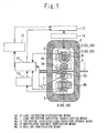
- FIG. 1 is a diagram showing the general configuration of a control apparatus of a rolling mill in a first embodiment according to the present invention.
- reference numeral 1 denotes a rolled material, which is made of a metal material
- reference numeral 2 denotes a housing of a rolling mill
- reference numeral 3 denotes a work roll
- reference numeral 4 denotes a back up roll.
- the rolled material 1 is rolled by the work rolls 3 whose roll gaps and speeds are appropriately adjusted so that a desired thickness is obtained on the exit side of the rolling mill.
- a 4Hi mill is shown as an example of a rolling mill. That is, in this embodiment, the work roll 3 includes a top work roll 3a and a bottom work roll 3b.
- the back up roll 4 includes a top back up roll 4a and a bottom back up roll 4b.
- the work roll 3 is configured in such a manner as to be supported by the back up roll 4 so that deflection in the roll width direction becomes small.
- the top work roll 3a is supported by the top back up roll 4a from above
- the bottom work roll 3b is supported by the bottom back up roll 4b from below.
- the back up roll 4 is supported by the housing 2, and has a prescribed structure capable of sufficiently withstanding the load during the rolling of the rolled material 1.
- Reference numeral 5 denotes a screw-down device.
- the gap between the top work roll 3a and the bottom work roll 3b, i.e., the roll gap is adjusted by this screw-down device 5.
- screw-down devices 5 there are two types of screw-down devices 5: a screw-down device by motor control (called a motor-driven screw-down device) and a screw-down device by hydraulic control (called a hydraulic screw-down device), high-speed responses can easily be obtained in a hydraulic screw-down device. Because high-speed responses are necessary for controlling short-period disturbances such as roll eccentricity, a hydraulic screw-down device is generally adopted for rolling mills.
- a rolling mill is divided into what is called a drive side where motors and drive units are disposed and an operator side where an operating room is disposed, the side opposite to the drive side, based on the rolling line as a boundary.
- the suffix D or DR is used to express the drive side
- the suffix O or OP is used to express the operator side.
- the screw-down device 5 is installed on both the drive side and the operator side. That is, a screw-down device 5D is installed on the drive side of the rolling mill and a screw-down device 50 is installed on the operator side.
- the roll gap is adjusted using both screw-down devices 5D and 5O.
- Reference numeral 6 denotes a load detecting device for detecting loads in a rolling mill.
- the load detecting device 6 is installed on the drive side and the operator side. That is, a load detecting device 6D is installed on the drive side of the rolling mill and a load detecting device 60 is installed on the operator side.
- load detection methods There are various methods as load detection methods.
- the load detecting device 6 detects load directly by a load cell embedded between the housing 2 and the screw-down device 5.
- the load detecting device 6 indirectly calculates loads on the basis of pressures detected in a hydraulic screw-down device.
- “Load” includes both a rolling load and a load in a kiss-roll condition.
- a rolling load is a load equivalent to the rolling reaction force from the rolled material 1 while the rolled material 1 is being rolled.
- a load in a kiss-roll condition is a load generated in what is called a kiss-roll condition in which the top work roll 3a and the bottom work roll 3b are brought into contact with each other when there is no rolled material 1. In the following, in the case where it is unnecessary to make a clear discrimination between a load in a kiss-roll condition and a rolling load, "load” is simply used.
- Reference numeral 7 denotes a roll rotation speed detector for detecting the rotation speed of the work roll 3 (or the back up roll 4).
- the roll rotation speed detector 7 is provided in the work roll 3 or a shaft of an electric motor (not shown) which drives this work roll 3.
- the configuration may be such that as one function of the roll rotation speed detector 7, pulses responding to the rotational angle of the work roll 3 are outputted. With this configuration, it becomes possible to detect the rotational angle of the work roll 3 by use of the roll rotation speed detector 7.
- Reference numeral 8 denotes a roll reference position detector which detects a prescribed reference position each time the back up roll 4 rotates one turn.
- the roll reference position detector 8 is provided with, for example, a proximity sensor, and detects an object to be detected (i.e., the reference position) provided in the back up roll 4 each time the back up roll 4 rotates one turn.
- the roll reference position detector 8 may have any configuration so long as it has the detection function for reference position. For example, by using a pulse generator, the roll reference position detector 8 may detect the rotational angle itself of the back up roll 4 by taking out a pulse dependent on the rotational angle of the back up roll 4.
- FIG. 1 shows the case where the roll reference position detector 8 is provided on both the top back up roll 4a and the bottom back up roll 4b. If the above-described function can be realized, the roll reference position detector 8 may be attached to only either the top back up roll 4a or the bottom back up roll 4b. Even when the roll reference position detector 8 is not provided as a discrete device, if the ratio of the diameter of the work roll 3 to the diameter of the back up roll 4 is known, it is also possible to find, by computation, the rotational angle of the back up roll 4 from the rotational angle of the work roll 3.
- Reference numeral 9 denotes a roll gap detector for detecting the roll gap.
- the roll gap detector 9 is provided, for example, between the back up roll 4 and the screw-down device 5, and indirectly detects the roll gap.
- the roll gap detector 9 is installed on both the drive side and the operator side. That is, a roll gap detector 9D is installed on the drive side of the rolling mill, and a roll gap detector 90 is installed on the operator side.
- Reference numeral 10 denotes load top/bottom distribution means
- reference numeral 11 denotes load top/bottom variation identification means
- reference numeral 12 denotes top/bottom identified load variation storage means
- reference numeral 13 denotes manipulated variable computation means
- reference numeral 14 denotes roll gap manipulation means.
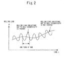
- FIG 2 is a diagram showing the concept of the rolling load to be measured.
- the load during the rolling of the rolled material 1 varies with the lapse of time (i.e., the rotation of rolls), for example, due to changes in the temperature of the rolled material 1 and changes in plate thickness even in the case where a periodic disturbance mainly caused by the roll eccentricity of the back up roll 4 does not occur.
- the rolling load is expressed by a load obtained by adding variation components of rolling load due to roll eccentricity and the like to variations caused by factors other than the roll eccentricity and the like.
- the present invention has the basic concept that by accurately separating variation components due to roll eccentricity and the like from the rolling load, the separated variation components (i.e., rolling load variations due to roll eccentricity and the like) are controlled by this control apparatus, and rolling load variations due to factors other than roll eccentricity and the like are controlled by the above-described MMC and GM-AGC.
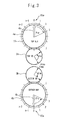
- Figure 3 is a diagram to explain a relationship between the division of the back up roll and the work roll. Specifically, Figure 3 shows the case where the whole circumference of the back up roll 4 is divided into n equal parts and a corresponding position scale mark 15 is provided on the outer side of the back up roll 4 in the vicinity thereof.
- the position scale mark 15 is provided to explain the function and the like of each of the means 10 to 14, and it is not always necessary that the position scale mark 15 be provided in actual devices.
- the position scale mark 15 is intended for detecting the rotational position of the back up roll 4 and is provided on the housing 2 side. That is, the position scale mark 15 does not rotate with the back up roll 4.
- a reference position 4c on the rotation side is set beforehand on the back up roll 4. This reference position 4c is set in a certain position of the back up roll 4 and rotates naturally in response to the rotation of the back up roll 4.
- the roll reference position detector 8 can be constituted by using the sensor and the object to be detected.
- the proximity sensor disposed in the reference position 4c reaches the reference position 15a on the fixed side
- the object to be detected which is embedded in the reference position 15a
- the proximity sensor is detected by the proximity sensor. That is, it is recognized that the reference position 4c of the back up roll 4 has passed the reference position 15a on the fixed side.
- ⁇ WTO shown in Figure 4 is the rotational angle of the top work roll 3a that is obtained when the reference position 4c of the top back up roll 4a coincides with the reference position 15a on the fixed side, while ⁇ WT is the rotational angle of the top work roll 3a when the top back up roll 4a has rotated by ⁇ BT .
- the suffix T on the right side indicates the top side, and the suffix B indicates the bottom side.
- the rotational angle of the back up roll 4 refers to the angle formed when the reference position 4c on the rotation side moves in response to the rotation of the back up roll 4 from the reference position 15a on the fixed side.
- the fact that the rotational angle of the back up roll 4 is 90 degrees states that the reference position 4c is in a position obtained when the reference position 4c has rotated 90 degrees from the reference position 15a on the fixed side in the rotational direction of the back up roll 4.
- the condition in which the rotational angle of the back up roll 4 is at the nearest scale mark in the position scale mark 15 refers to the fact that the rotational angle number (corresponding to the rotational position) of the back up roll 4 is j.
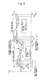
- FIG. 4 is a diagram to explain an example of extracting variation components due to roll eccentricity and the like from loads.
- a detected load is a rolling load as an example.
- the rolling load indicates P 10 .
- the rolling load also changes to P 11 , P 12 , P 13 ....
- the rolling load rotates one turn and the rotational angle number becomes from (n - 1) to 0 again, the rolling load P 20 is sampled.
- the straight line connecting the rolling loads P 10 and P 20 can be regarded as the rolling load in which rolling load variations due to roll eccentricity and the like are removed. Therefore, variation components of rolling load due to roll eccentricity and the like can be found from differences between the rolling loads P 10 , P 11 , P 12 , P 13 ... P 20 which are measured at each rotational angle number and the above-described straight line.
- Values of actually measured rolling load P ij often include noise components in addition to rolling load variations due to temperature variation, plate thickness variation, tension variation and the like and rolling load variations due to roll eccentricity and the like. For this reason, the actual values of actual rolling load P ij are not distributed on a gentle curve as shown in Figure 4 , and in some cases, it is difficult to identify a rolling load P i0 which becomes a start point of the above-described straight line and a rolling load P (i + 1)0 which becomes an end point.
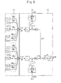
- Figures 5 and 6 are detail views of the main parts of the control apparatus of a rolling mill shown in Figure 1 . Specifically, Figure 5 shows detail views of the load top/bottom distribution means 10 and the load top/bottom variation identification means 11, and Figure 6 shows detail views of the top/bottom identified load variation storage means 12 and the manipulated variable computation means 13.
- the load top/bottom distribution means 10 has the function of separating a load (for example, an actual value of rolling load) detected by the load detecting device 6 into two values.
- the load detecting device 6 can obtain only one value as the load for one stand.
- a total load P which is the sum of a load detected by the load detecting device 6D and a load detected by the load detecting device 60 is inputted to the load top/bottom distribution means 10.
- the load top/bottom distribution means 10 assumes that this total load P detected by the load detecting device 6 be generated individually at the top back up roll 4a and the bottom back up roll 4b, and divides the total load P into a top side load P T and a bottom side load P B .
- the load top/bottom distribution means 10 performs the distribution of the total load P by the following expressions:
- the load top/bottom distribution means 10 outputs the values P T and P B which are obtained by distributing the total load P to two of the top and bottom side loads, to the load top/bottom variation identification means 11.
- the load top/bottom variation identification means 11 is provided with top side load variation identification means 16 and bottom side load variation identification means 17.
- the top side load variation identification means 16 has the function of identifying a variation component of the top side load generated in connection with the rotational position of rolls from the top side load P T distributed by the load top/bottom distribution means 10 and the function of outputting the identification data (the top side variation component) to the manipulated variable computation means 13 at appropriate timing.
- the bottom side load variation identification means 17 has the function of identifying a variation component of the bottom side load generated in connection with the rotational position of rolls from the bottom side load P B distributed by the load top/bottom distribution means 10 and the function of outputting the identification data (the bottom side variation component) to the manipulated variable computation means 13 at appropriate timing.
- a concrete description will be given of the configurations and functions of the top side load variation identification means 16 and the bottom side load variation identification means 17.
- the main part of the top side load variation identification means 16 is composed of deviation computation means 18a, identification means 19a, and a switch 20a.
- the top side load P T generated when the rotational angle number of the back up roll 4 is 0 is recorded as the load P 0 in the record area 21a.
- the top side load P T generated when the rotational angle number of the back up roll 4 is j is recorded as the load P j in the record area 21a.
- the top side load P T from the load top/bottom distribution means 10 is held in the record area 21a while the back up roll 4 is rotating one turn.
- the load P j is recorded in all record areas 21a (for example, when the top side load P T with the rotational angle number as n - 1, is recorded as the load P n - 1 in the record area 21a)
- the average value of loads recoded in each record area 21 a is computed by average value computation means 22a.
- a subtractor 23 a computes, for each rotational angle number, the difference ⁇ P j between the load P j in the record area 21a and the average value computed by the average value computation means 22a.
- the computation result (the above-described difference) of the subtractor 23a is equivalent to the deviation ⁇ P ij shown in Figure 4 , i.e., a variation component of load caused by roll eccentricity and the like.
- Figure 5 shows the configuration used when an average value is computed by the average value computation means 22a.
- the calculation of the deviation may be performed by finding the straight line explained in Figure 4 .
- the deviation computation means 18a makes computations using an expression of the straight line, with the load P o as a start point and the load P n as an end point, and calculates a difference between the straight line and the load P j at each rotational angle number.
- the deviation ⁇ P j outputted from the subtractor 23a i.e., a variation component of load due to roll eccentricity and the like is inputted to the identification means 19a and upper and lower limits are checked by a limiter 24a.
- each switch 25a is concurrently turned on and the deviation ⁇ P j is inputted to each adder 26a all at once.
- Each adder 26a performs the addition of the deviation ⁇ P j on the basis of the following expression.
- Each of the adders 26a is cleared to zero before the rolling of the rolled material 1 is rolled.
- the adder 26a performs the addition of the deviation ⁇ P j once each time the back up roll 4 rotates one turn and the computation of the average value by the average value computation means 22a is finished.
- Adding the deviation ⁇ P j for each rotational angle number can be easily explained by a general control rule. That is, in the case where there is no integration system in a controlled object as in this controlled object, removing a steady-state deviation by providing an integrator on the controller side is appropriate in terms of a control rule.
- adders are used instead of integrators because the controlled object is a discrete system, not a continuous system.
- a deviation of load i.e., identification data
- the bottom side load variation identification means 17 is provided with deviation computation means 18b, identification means 19b, and a switch 20b. Because the bottom side load variation identification means 17 has substantially the same function as the top side load variation identification means 16, a concrete description of each configuration is omitted.
- the main part of the deviation computation means 18b is composed of a record area 21b, average value computation means 22b, and a subtractor 23b.
- the identification means 19b is provided with a limiter 24b, a switch 25b, and an adder 26b.
- the top/bottom identified load variation storage means 12 has the function of storing values (added value) of the adders 26a and 26b at a given point for each rotational angle number of the back up roll 4 and outputting the values at appropriate timing as required.
- the concrete configuration and function of the top/bottom identified load variation storage means 12 will be described later.
- the manipulated variable computation means 13 has the function of computing a roll gap instruction value in such a manner as to reduce variation components of loads caused by roll eccentricity and the like and outputting the computation result to the roll gap manipulation means 14. Specifically, the manipulated variable computation means 13 performs the computation of the instruction value on the basis of the top and bottom side load variation values ( ⁇ P AT and ⁇ P AB ) inputted from the load top/bottom variation identification means 11 and the storage contents (output values) of the top/bottom identified load variation storage means 12.
- the manipulated variable computation means 13 computes a roll gap instruction value responding to each rotational position of rolls and reduces plate thickness variations of the rolled material 1. Specifically, the manipulated variable computation means 13 computes an amount of correction of roll gap ⁇ S (mm) in each rotational position of rolls on the basis of the following expressions.
- the roll gap cannot be manipulated individually on the top and bottom sides. For this reason, it is necessary that the manipulated variable computation means 13 outputs an instruction value for the roll gap manipulation means 14 by adding an amount of correction for the top and bottom sides.
- M Mill constant Q : Plastic coefficient of rolled material
- K T , K T1 , K B1 Adjustment coefficient
- ⁇ S T Amount of correction of roll gap for top back up roll
- ⁇ S B Amount of correction of roll gap for bottom back up roll
- ⁇ S Amount of correction of roll gap ⁇ P AT Deviation of rolling load by top back up roll (output of the top side load variation identification means 16)
- ⁇ P AB Deviation of rolling load by bottom back up roll (output of the bottom side load variation identification means 17)
- the manipulated variable computation means 13 outputs a computed amount of correction of roll gap ⁇ S (mm) to the roll gap manipulation means 14.
- the roll gap is a positive value in the open direction and a negative value in the closed direction. The same applies to the following.
- the amount of correction of roll gap ⁇ S which is an output of the manipulated variable computation means 13, is intended for compensating for variation components of loads which are caused by roll eccentricity and the like.
- the roll gap manipulation means 14 adds the amount of correction of roll gap ⁇ S from the manipulated variable computation means 13 to the amount of roll gap obtained by MMC, GM-AGC or the like, and outputs the resulting amount of roll gap to the screw-down device 5, thereby appropriately manipulating the roll gap.
- the roll gap manipulation means 14 is configured in such a manner as to be able to individually control a roll gap on the drive side and a roll gap on the operator side. This is because in the case where one end portion of the rolled material 1 is elongated during rolling of the rolled material 1, the rolls are moved so that the roll gap on the side of the elongated end portion becomes large to make corrections. In the case where it is unnecessary to individually control the roll gaps on the drive side and the operator side, the roll gap manipulation means 14 outputs, for example, an instruction value of the same value to the drive side screw-down device 5D and the operator side screw-down device 5O.
- the adders 26a and 26b of the load top/bottom variation identification means 11 are cleared to zero before the rolling of the rolled material 1.
- identification data is not accumulated in the adders 26a and 26b, and therefore, it is impossible to output load variation values ( ⁇ P AT and ⁇ P AB ).
- gauge control is performed also using identification date prepared beforehand.
- identification date prepared beforehand.
- control before the start of the rolled material 1, control is performed in such a manner that the rolls are rotated at a given speed in a kiss-roll condition, whereby loads are generated.
- the load top/bottom variation identification means 11 is caused to perform the same control as that during the rolling of the rolled material 1 (the above-described control explained using Figure 5 ), to thereby output a top side variation component ⁇ P AT and a bottom side variation component ⁇ P AB of the load in a kiss-roll condition, which have been identified, to the manipulated variable computation means 13. That is, in this control, P shown in Figure 5 becomes the load in a kiss-roll condition.
- the manipulated variable computation means 13 computes a roll gap instruction value responding to each rotational position of rolls in such a manner as to reduce variation components of the load in a kiss-roll condition occurring in connection with the rotational position of rolls, and causes the roll gap manipulation means 14 to perform the control of the screw-down device 5.
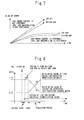
- Figure 7 is a diagram to explain the value of the adder observed when a load is caused to be generated in a kiss-roll condition.
- a roll gap adjustment i.e., a roll gap adjustment
- the rolls are caused to rotate in a kiss-roll condition, in the case where neither a computation by the manipulated variable computation means 13 nor a manipulation by the roll gap manipulation means 14 (i.e., a roll gap adjustment) is performed, a fixed value is added to the adders 26a and 26b of the load top/bottom variation identification means 11 for each rotation of the rolls. For this reason, the values of the adders 26a and 26b increase with time in an ever-increasing manner.
- the roll gap is manipulated in such a manner as to be in proportion to the disturbance components. Therefore, the amount of increase in the added value gradually decreases and becomes a given value after the elapse of a given period of time.
- the top/bottom identified load variation storage means 12 stores, for each rotational angle number of the back up roll 4, the values of the adders 26a and 26b at this time, i.e., the top side variation component and bottom side variation component of the load in a kiss-roll condition which are identified by the load top/bottom variation identification means 11.
- the top/bottom identified load variation storage means 12 stores, for each rotational angle number of the back up roll 4, the values of the adders 26a and 26b obtained after the elapse of a prescribed period of time after the start of the control in a kiss-roll condition.
- the top/bottom identified load variation storage means 12 monitors the values of the adders 26a and 26b and stores, for each rotational angle number of the back up roll 4, the values of the adders 26a and 26b obtained when the variations of the values (for example, amounts of increase in a prescribed period of time) have fallen in a prescribed range.
- the manipulated variable computation means 13 performs the computation of an amount of correction of roll gap ⁇ S (mm) also in consideration of the storage contents of the top/bottom identified load variation storage means 12.
- Figure 8 is a diagram to explain the control contents of the manipulated variable computation means for the duration from the start of rolling until a prescribed transition period has elapsed.
- the manipulated variable computation means 13 performs the computation of the amount of correction ⁇ S (mm) using only the storage contents (i.e., the top side variation component and bottom side variation component of the load in a kiss-roll condition) of the top/bottom identified load variation storage means 12 without using the top side variation component and bottom side variation component of the rolling load which are identified by the load top/bottom variation identification means 11.
- the manipulated variable computation means 13 performs the computation of the amount of correction ⁇ S (mm) using both the top side variation component and bottom side variation component of the rolling load which are identified by the load top/bottom variation identification means 11, i.e., the values of the adders 26a and 26b and the storage contents of the top/bottom identified load variation storage means 12.
- the manipulated variable computation means 13 increases the ratio of using the top side variation component and bottom side variation component of the rolling load which are identified by the load top/bottom variation identification means 11, with the lapse of time, whereby it is ensured that the effect of an actual rolling load greatly manifests itself.
- Figure 8 although changes in the use ratio are indicated by straight lines, the changes may be indicated by quadratic curves and EXP curves.
- the manipulated variable computation means 13 performs the computation of the amount of correction ⁇ S (mm) only using the top side variation component and bottom side variation component of the rolling load which are identified by the load top/bottom variation identification means 11, without using the storage contents of the top/bottom identified load variation storage means 12.
- control apparatus in the gauge control during the rolling of a metal material, it is possible to appropriately reduce periodic disturbances caused by the roll eccentricity and the like.
- this control apparatus it is possible to solve also the problem in the roll eccentricity control 1 in (A) and the problem in the roll eccentricity control 2 in (B), which have been described above. Furthermore, with this control apparatus, it is possible to realize highly accurate gauge control even at an extreme leading end of the rolled material 1, making it possible to supply high-quality products.
- the ratio R of the total load P to be distributed to the load P T be set at a value in the vicinity of 0.5. That is, a value close to 1/2 of the total load P is distributed to a load generated in the top back up roll 4a and a load generated in the bottom back up roll 4b.
- one of the top and bottom adders 26a, 26b can almost completely cancel the rolling load variation component due to roll eccentricity and the like by the counterpart of the back up roll 4a or 4b.
- it is also possible to adjust the value of R by making a comparison between the values of the adders 26a and 26b which are the results of the identification.
- R is preferably in the range from not less than 0.4 to not more than 0.6.
- FIG. 9 is a diagram showing the general configuration of a control apparatus of a rolling mill in a second embodiment according to the present invention.
- reference numeral 27 denotes roll gap top/bottom variation identification means
- reference numeral 28 denotes top/bottom identified roll gap variation storage means
- reference numeral 29 denotes manipulated variable computation means.
- the rolling load sometimes shows changes in the amplitude of variations depending on the width, deformation resistance (hardness) and the like of the rolled material 1. Therefore, in this embodiment, a description will be given of the case where a load signal is converted to a value corresponding to a roll gap and then, accumulated to the adder. With this configuration, it becomes possible to retain and store a signal as a quantity which depends on the structure of a rolling mill and does not depend on the size or characteristics, such as hardness, of the rolled material 1.
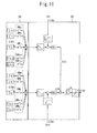
- Figures 10 and 11 are detail views of the main parts of the control apparatus of a rolling mill shown in Figure 9 , and show portions corresponding to Figures 5 and 6 , respectively. Specifically, Figure 10 shows detail views of the load top/bottom distribution means 10 and the roll gap top/bottom variation identification means 27, and Figure 11 shows detail views of the top/bottom identified roll gap variation storage means 28 and the manipulated variable computation means 29.
- the roll gap top/bottom variation identification means 27 is provided with top side roll gap variation identification means 30 and bottom side roll gap variation identification means 31.
- the top side roll gap variation identification means 30 has the function of identifying a roll gap variation component occurring in connection with the rotational position of rolls from the top side load P T distributed by the load top/bottom distribution means 10 and the function of outputting the identification data (the top side variation component) to the manipulated variable computation means 29 at appropriate timing.
- the bottom side roll gap variation identification means 31 has the function of identifying a roll gap variation component occurring in connection with the rotational position of rolls from the bottom side load P B distributed by the load top/bottom distribution means 10 and the function of outputting the identification data (the bottom side variation component) to the manipulated variable computation means 29 at appropriate timing.
- the main part of the top side roll gap variation identification means 30 is composed of deviation computation means 32a, conversion means 33a, identification means 34a, and a switch 35a.
- the functions of the deviation computation means 32a, the identification means 34a, and the switch 35a are substantially the same as the functions of the above-described deviation computation means 18a, identification means 19a, and switch 20a. That is, the deviation computation means 32a is provided with a record area 36a, average value computation means 37a, and a subtractor 38a.
- the identification means 34a is provided with a limiter 39a, a switch 40a, and an adder 41a.
- the conversion means 33a has the function of converting the top side variation component of a load extracted by the deviation computation means 32a to the displacement of a roll gap.
- the conversion means 33a is provided between the deviation computation means 32a and the identification means 34a, and converts the deviation ⁇ P j outputted from the subtractor 38a, i.e., the variation component of the load caused by roll eccentricity and the like to a value corresponding to the roll gap on the basis of the following expression:
- the value ⁇ S j converted by the conversion means 33a is inputted to the identification means 34a and upper and lower limits thereof are checked by the limiter 39a.
- Each of the switches 40a is simultaneously turned on at the point when the check of the upper and lower limits of the converted value ⁇ S j of each rotational angle number is finished, and the converted value ⁇ S j is fed to each of the adders 41a all at once.
- Each of the adders 41a performs the same computation as that according to Expression 4 above and adds the converted value ⁇ S j , i.e., the top side displacement of the roll gap.
- the conversion means 33a may also be installed between the limiter 39a and the switch 40a or between the switch 40a and the adder 41a. Because the bottom side roll gap variation identification means 31 has the same configuration as the top side roll gap variation identification means 30, a concrete description thereof is omitted.
- this control apparatus performs gauge control also using identification data prepared beforehand. For this reason, in this control apparatus, before the start of the rolling of the rolled material 1, control is performed in such a manner that the rolls are rotated at a given speed in a kiss-roll condition and a load is thereby generated.
- the manipulated variable computation means 29 is caused to compute a roll gap instruction value responding to each rotational position of the rolls in such a manner as to reduce the roll gap variation component occurring in connection with the rotational position of the rolls, and the roll gap manipulation means 14 is caused to control the screw-down device 5.
- the conversion means 33a and 33b performs a conversion to a value corresponding to the roll gap on the basis of the following expression:
- the top/bottom identified roll gap variation storage means 28 stores, for each rotational position of rolls, the top side variation component and bottom side variation component of the roll gap which are identified by the roll gap top/bottom variation identification means 27, (i.e., the values of the adders 41a and 41b).
- the manipulated variable computation means 29 After the start of the rolling of the rolled material 1, in the same manner as in the first embodiment, on the basis of the top and bottom roll gap variation values ( ⁇ S AT and ⁇ S AB ) which are inputted from the roll gap top/bottom variation identification means 27, as well as the storage contents (output values) of the top/bottom identified roll gap variation storage means 28, the manipulated variable computation means 29 performs the computation of an instruction value for the roll gap manipulation means 14.
- control apparatus having the above-described configuration, it is possible to produce the same effect as in the first embodiment above. Furthermore, with the control apparatus of this embodiment, it is possible to store values which do not depend on the material characteristics of the rolled material 1 but depend only on the characteristics of the rolling mill in the adders 41a and 4 1 b as well as the top/bottom identified roll gap variation storage means 28. For this reason, even in the case where the characteristics of the rolled material 1, which becomes a controlled object, change, it is possible to restrict an adverse effect on control performance to a minimum extent and it is possible to supply high-quality products.
- FIG 12 is a diagram showing the rolling mill shown in Figure 1 as viewed from the rolling direction of a rolled material.
- roll gap variation components caused by the roll eccentricity and the like are not the same on the right and left sides of the rolled material 1, i.e., on the drive side and the operator side of the rolled material 1, for example, in the case where the construction of oil bearings used in the back up roll 4 is laterally asymmetrical.
- This control apparatus is provided with the screw-down device 5, the load detecting device 6, and the roll gap detector 9 on both the drive side and the operator side, and the mechanism of this control apparatus are such that a roll gap can be separately controlled on the drive side and the operator side.
- control is performed in such a manner that the rolls are rotated at a given speed in a kiss-roll condition and a load is thereby generated. Specifically, first, the rolls are rotated at a given speed in a kiss-roll condition and the load in a kiss-roll condition detected by the load detecting device 6D on the drive side is inputted to the load top/bottom distribution means 10. In this case, P shown in Figure 5 becomes the load in a kiss-roll condition detected by the load detecting device 6D on the drive side.
- the load top/bottom distribution means 10 divides the load P in a kiss-roll condition detected by the load detecting device 6D into the top side load P T and the bottom side load P B which are in turn outputted to the load top/bottom variation identification means 11. Also for the distribution ratio R at this time, a value in the vicinity of 0.5 (for example, a prescribed value of not less than 0.4 but not more than 0.6) is set.
- the load top/bottom variation identification means 11 On the basis of the inputted top side load P T and bottom side load P B , the load top/bottom variation identification means 11 identifies the top side variation component and bottom side variation component of the load in a kiss-roll condition, which respond to each rotational position of rolls, and outputs these variation components to the manipulated variable computation means 13 at appropriate timing.
- the manipulated variable computation means 13 computes a roll gap instruction value responding to each rotational position of rolls in such a manner as to reduce variation components of the load in a kiss-roll condition occurring in connection with the rotational position of rolls, and causes the roll gap manipulation means 14 to control the screw-down device 5.
- the top/bottom identified load variation storage means 12 stores, for each rotational angle number of the back up roll 4, the values of the adders 26a and 26b at this time, i.e., the top side variation component and bottom side variation component of the load in a kiss-roll condition on the drive side which are appropriately identified by the load top/bottom variation identification means 11.
- the rolls are rotated in a kiss-roll condition at a given speed and the same control as described above is performed also on the operator side.
- the top side variation component and bottom side variation component of the load in a kiss-roll condition on the operator side which are identified by the load top/bottom variation identification means 11, are stored in the top/bottom identified load variation storage means 12 for each rotational angle number of the back up roll 4.
- the manipulated variable computation means 13 performs the computation of a roll gap instruction value ⁇ S RF on the basis of the top and bottom load variation values ( ⁇ P AT and ⁇ P AB ) inputted from the load top/bottom variation identification means 11 as well as the storage contents of the top/bottom identified load variation storage means 12.
- the computed instruction value ⁇ S RF is a value for controlling the plate thickness of the rolled material 1 in the middle part of the width direction.
- the manipulated variable computation means 13 further computes an instruction value on the drive side and an instruction value on the operator side from the instruction value ⁇ S RF on the basis of the storage contents of the top/bottom identified load variation storage means 12, and outputs the computation results to the roll gap manipulation means 14.
- Figure 13 is a diagram to explain a method of computing roll gap instruction values on the drive side and the operator side.
- the manipulated variable computation means 13 performs the computation of an instruction value on the drive side and an instruction value on the operator side from the roll gap instruction value ⁇ S RF on the basis of the following expressions:
- r DR Ratio of the bottom side variation component to the top side variation component of the load in a kiss-roll condition on the drive side, both variation components being stored in the top/bottom identified load variation storage means 12
- r OP Ratio of the bottom side variation component to the top side variation component of the load in a kiss-roll condition on the operator side, both variation components being stored in the top/bottom identified load variation storage means 12
- K TDR , K TOP Adjustment coefficient ⁇ S DR : Roll gap instruction value on the drive side
- ⁇ S OP Roll gap instruction value on the operator side
- the roll gap manipulation means 14 outputs the inputted instruction value ⁇ S DR on the drive side to the screw-down device 5D side and the instruction value ⁇ S OP on the operator side to the screw-down device 50 side, and appropriately manipulates the roll gap on the right and left sides.
- Figures 14 and 15 are diagrams to explain methods of computing the ratios r DR and r OP .
- the ordinates indicate the variation components of the load in a kiss-roll condition which are stored in the top/bottom identified load variation storage means 12, and the abscissas indicate the rotational positions of rolls.
- the back up roll 4 is divided into 60 parts, scale marks of 0 to 59 are given on the abscissa.
- Figure 14 shows the case where the ratios r DR and r OP are computed from the maximum value and minimum value of the variation components.
- the ratios r DR and r OP are indicated as the ratio of a peak value of the bottom side variation component to the peak value of the top side variation component of the load in a kiss-roll condition, both variation components being stored in the top/bottom identified load variation storage means 12.
- Figure 15 shows the case where the ratios r DR and r OP are computed from the hatched areas.
- the ratios r DR and r OP are each expressed as the ratio of a value obtained by integrating the absolute value of the bottom side variation component, to a value obtained by integrating the absolute value of the top side variation component of the load in a kiss-roll condition, both variation components being stored in the top/bottom identified load variation storage means 12.
- the above-described functions peculiar to this embodiment can also be applied to the configuration described in the second embodiment.
- the top side variation component and bottom side variation component of the roll gap on the drive side which are identified by the roll gap top/bottom variation identification means 27 in a kiss-roll condition, as well as the top side variation component and bottom side variation component of the roll gap on the operator side are stored for each rotational position of rolls in the top/bottom identified roll gap variation storage means 28.
- the manipulated variable computation means 29 computes an instruction value on the drive side and an instruction value on the operator side on the basis of Expressions 10 and 11.
- the ordinates of Figures 14 and 15 indicate variation components of roll gap.
- control apparatus of a rolling mill of the present invention can be applied to the gauge control during the rolling of metal materials.
Landscapes
- Engineering & Computer Science (AREA)
- Mechanical Engineering (AREA)
- Control Of Metal Rolling (AREA)
Abstract
Description
- The present invention relates to a control apparatus for reducing periodic disturbances, for example, load variations which periodically occur with respect to the rotation position of rolls and the like and gauge variations which occur as a result of the load variations, in the gauge control during the rolling of a metal material.
- One of quality control methods in sheet rolling and plate rolling is automatic gauge control (AGC) which involves controlling the plate thickness of a rolled material in the middle part of the width direction. Examples of concrete control methods include monitor AGC which involves feeding back measured values of a plate thickness gauge installed on the exit side of a rolling mill, gauge meter AGC (GM-AGC) which involves using gauge meter plate thicknesses estimated from rolling loads and roll gaps (the clearance between top and bottom work rolls), and mill modulus control (MMC) which involves using rolling loads.
- For example, in the case of hot rolling, temperature variations of rolled materials can be mentioned as disturbances which hinder an improvement in thickness accuracy. As disturbances common to hot rolling and cold rolling, other kinds of control items, for example, tension variations due to the deterioration of tension control, changes in speed or roll gap by an operator's manual intervention, roll eccentricity caused by accuracy deficiencies of the roll structure or roll grinding can be mentioned.
- Among these disturbances, the main cause of the above-described roll eccentricity is that when key grooves of support rolls having oil bearings are subjected to a rolling load of as large as several hundreds of tons to two to three thousands of tons, shafts move up and down (undergo shaft oscillation). When roll eccentricity occurs, variations in roll gap occur correspondingly to the rotation of rolls.
Even in the case of rolls not provided with key grooves, periodic roll gap variations dependent on the rotation of the rolls occur caused by asymmetry during roll grinding and uneven thermal expansion, for example. - A rolling mill is provided with a roll gap detector for detecting roll gaps, and a device which controls roll gaps controls a screw-down device by feeding back detected values of the roll gap detector so that the roll gap obtains a given value (a set value). However, disturbances dependent on the shaft oscillation of rolls, such as roll eccentricity, cannot be detected by a roll gap detector. That is, the effect of the shaft oscillation of rolls does not manifest itself in detected values of the roll gap detector. For this reason, it is impossible to perform such control as to suppress the disturbances dependent on the shaft oscillation of rolls even when a roll gap detector is used. However, because in actuality, the disturbances dependent on the shaft oscillation of rolls change roll gaps, the effect of the shaft oscillation of rolls manifests itself in rolling loads. Therefore, the disturbances dependent on the shaft oscillation of rolls provides a great factor responsible for hindering an improvement in thickness accuracy in GM-AGC, MMC and the like which involve performing gauge control using rolling loads.
- In order to reduce disturbances which periodically occur (hereinafter, referred to as "periodic disturbances") such as roll eccentricity, roll eccentricity control has hitherto been performed. Some examples related to roll eccentricity control are described below.
- In the following descriptions (including the description of the present invention), the same concept can be used in the case of what is called a 2Hi mill, which is composed of only two of the top and bottom work rolls, the case of what is called a 4Hi mill, which is composed of a total of four rolls: two of the top and bottom work rolls and two of the top and bottom support rolls, and the case of what is called a 6Hi mill, which is composed of a total of six rolls: two of the top and bottom work rolls, two of the top and bottom intermediate rolls, and two of the top and bottom support rolls, and even in the case of a mill composed of not less than six rolls. For this reason, in the following, the terms "WR" for work roll and "BUR" for back up roll, which are rolls other than work rolls, are used.
- Before the rolling of a rolled material, the top and bottom work rolls are brought into contact with each other, and the rolls are rotated, with a given load applied to the rolls (in a kiss-roll condition), and a load in the kiss-roll condition is detected. Then, roll eccentricity frequencies are analyzed by performing the fast Fourier transformation and the like of the detected load in the kiss-roll condition. During rolling, it is assumed that roll eccentricity at the analyzed frequency occur, and a manipulated variable of roll gap is outputted in such a manner as to reduce the effect of the above-described roll eccentricity without performing feedback control using loading loads.
- Plate thickness variations are measured using a plate thickness gauge installed on the exit side of a rolling mill. Then, a thickness deviation is computed linking at which rotation positions of rolls, values measured by the plate thickness gauge have been obtained during rolling. The control apparatus manipulates roll gaps according to the computed thickness deviation and reduces the thickness variations due to roll eccentricity.
- During rolling, rolling loads are detected and roll eccentricity components are extracted from the rolling loads. Then, the extracted roll eccentricity components are converted to roll gap signals, and roll gaps are manipulated so that the rolling load variations due to the roll eccentricity are reduced (refer to
Patent Literature 1 and Patent Literature 2). -
- Patent Literature 1 : Japanese Patent Laid-Open No.
2002-282917 - Patent Literature 2: International Patent Publication No.
WO2008/090596 - Because problems in the above-described roll eccentricity controls 1 and 2 as well as problems in
roll eccentricity control 3 described inPatent Literature 1 are described inPatent Literature 2, descriptions of these problems are omitted here. - As described in
Patent Literature 2, in the case where the diameters of top and bottom buck up rolls are different, a phenomenon what is called beat or waviness occurs and deteriorated control occurs.
In the roll eccentricity control described inPatent Literature 2, although a roll gap manipulation is performed by appropriately extracting roll eccentricity components from loads during rolling, there occurs the problem that high-accuracy gauge control cannot be performed for the extreme leading end of a rolled material. - For example, in the gauge control of an extreme leading end of a rolled material,
Patent Literature 2 describes using a value obtained during the rolling of material immediately before the rolling in question (in particular, refer to paragraph 0069). However, this method has the problem that in the case where after the detection of the value, a shift occurs in roll position due to the slip of back up rolls and work rolls, it is impossible to carry out accurate gauge control. -
Patent Literature 2 also describes a method in which means for extracting load variations in a kiss-roll condition is separately provided, whereby roll eccentricity components are extracted from the load in a kiss-roll condition and the components are used in the gauge control for an extreme leading end of a rolled material (in particular, refer to paragraphs 0070 and 0037). However, also in this case, there is a problem that, because of a difference between the extraction method in a kiss-roll condition and the extraction method during rolling, high-accuracy gauge control cannot be carried out, and furthermore, the configuration becomes complex. - This invention was made to solve the problems described above, and an object of the invention is to provide a control apparatus of a rolling mill which enables periodic disturbances caused by roll eccentricity and the like to be appropriately suppressed in the gauge control during the rolling of a metal material, and furthermore, which enables high-accuracy gauge control to be realized also in the rolling of an extreme leading end of a rolled material.
- A control apparatus of a rolling mill of the invention is a control apparatus for reducing periodic disturbances which are caused mainly by roll eccentricity, in gauge control during rolling of a metal material. The control apparatus comprises a load detecting device for detecting a load in a kiss-roll condition and a rolling load, load top/bottom distribution means which distributes loads detected by the load detecting device as a top side load and a bottom side load at a prescribed ratio, load top/bottom variation identification means which identifies load variation components occurring in connection with a rotational position of rolls from the top side load and the bottom side load which are distributed by the load top/bottom distribution means, top/bottom identified load variation storage means which stores, for each rotational position of rolls, a top side variation component and a bottom side variation component of the load in a kiss-roll condition which are identified by the load top/bottom variation identification means, manipulated variable computation means which computes a roll gap instruction value responding to each rotational position of rolls on the basis of the top side variation component and the bottom side variation component of the rolling load which are identified by the load top/bottom variation identification means, as well as the top side variation component and the bottom side variation component of the load in a kiss-roll condition which are stored in the top/bottom identified load variation storage means, in such a manner as to reduce plate thickness variations of a metal material which is being rolled, and roll gap manipulation means which manipulates a roll gap on the basis of the roll gap instruction value computed by the manipulated variable computation means.
- Also, a control apparatus of a rolling mill of the invention is a control apparatus which for reducing periodic disturbances which are caused mainly by roll eccentricity, in gauge control during rolling of a metal material. The control apparatus comprises a load detecting device for detecting a load in a kiss-roll condition and a rolling load, load top/bottom distribution means which distributes loads detected by the load detecting device as a top side load and a bottom side load at a prescribed ratio, roll gap top/bottom variation identification means which identifies roll gap variation components occurring in connection with a rotational position of rolls from the top side load and the bottom side load which are distributed by the load top/bottom distribution means, top/bottom identified roll gap variation storage means which stores, for each rotational position of rolls, a top side variation component and a bottom side variation component of a roll gap which are identified by the roll gap top/bottom variation identification means in a kiss-roll condition, manipulated variable computation means which computes a roll gap instruction value responding to each rotational position of rolls on the basis of the top side variation component and the bottom side variation component of the roll gap which are identified by the roll gap top/bottom variation identification means during the rolling of the metal material, as well as the top side variation component and the bottom side variation component of the roll gap which are stored in the top/bottom identified roll gap variation storage means, in such a manner as to reduce plate thickness variations of the metal material which is being rolled, and roll gap manipulation means which manipulates a roll gap on the basis of the roll gap instruction value computed by the manipulated variable computation means.
- According to the control apparatus of a rolling mill of this invention, it becomes possible to appropriately suppress periodic disturbances caused by roll eccentricity and the like in the gauge control during the rolling of a metal material, and furthermore, to realize high-accuracy gauge control also in the rolling of an extreme leading end of a rolled material.
-
-
Figure 1 is a diagram showing the general configuration of a control apparatus of a rolling mill in a first embodiment according to the present invention. -
Figure 2 is a diagram showing the concept of the rolling load to be measured. -
Figure 3 is a diagram to explain a relationship between the division of a back up roll and a work roll. -
Figure 4 is a diagram to explain an example of extracting variation components due to roll eccentricity and the like from loads. -
Figure 5 is a detail view of the main part of the control apparatus of a rolling mill shown inFigure 1 . -
Figure 6 is a detail view of the main part of the control apparatus of a rolling mill shown inFigure 1 . -
Figure 7 is a diagram to explain a value of an adder observed when a load is caused to be generated in a kiss-roll condition. -
Figure 8 is a diagram to explain the control contents of a manipulated variable computation means for the duration from the start of rolling until a prescribed transition period has elapsed. -
Figure 9 is a diagram showing the general configuration of a control apparatus of a rolling mill in a second embodiment according to the present invention. -
Figure 10 is a detail view of the main part of the control apparatus of a rolling mill shown inFigure 9 . -
Figure 11 is a detail view of the main part of the control apparatus of a rolling mill shown inFigure 9 . -
Figure 12 is a diagram showing the rolling mill shown inFigure 1 as viewed from the rolling direction of a rolled material. -
Figure 13 is a diagram to explain a method of computing roll gap instruction values on the drive side and the operator side. -
Figure 14 is a diagram to explain methods of computing the ratios rDR and rop. -
Figure 15 is a diagram to explain methods of computing the ratios rDR and rOP. - The present invention will be described in more detail with reference to the accompanying drawings. Incidentally, in each of the drawings, like numerals refer to like or corresponding parts and redundant descriptions of these parts are appropriately simplified or omitted.
-
Figure 1 is a diagram showing the general configuration of a control apparatus of a rolling mill in a first embodiment according to the present invention.
InFigure 1 ,reference numeral 1 denotes a rolled material, which is made of a metal material,reference numeral 2 denotes a housing of a rolling mill,reference numeral 3 denotes a work roll, andreference numeral 4 denotes a back up roll. The rolledmaterial 1 is rolled by the work rolls 3 whose roll gaps and speeds are appropriately adjusted so that a desired thickness is obtained on the exit side of the rolling mill. - In
Figure 1 , a 4Hi mill is shown as an example of a rolling mill. That is, in this embodiment, thework roll 3 includes atop work roll 3a and abottom work roll 3b. The back uproll 4 includes a top back uproll 4a and a bottom back uproll 4b. Thework roll 3 is configured in such a manner as to be supported by the back uproll 4 so that deflection in the roll width direction becomes small. Specifically, thetop work roll 3a is supported by the top back uproll 4a from above, and thebottom work roll 3b is supported by the bottom back uproll 4b from below. The back uproll 4 is supported by thehousing 2, and has a prescribed structure capable of sufficiently withstanding the load during the rolling of the rolledmaterial 1. -
Reference numeral 5 denotes a screw-down device. The gap between thetop work roll 3a and thebottom work roll 3b, i.e., the roll gap is adjusted by this screw-downdevice 5. Although there are two types of screw-down devices 5: a screw-down device by motor control (called a motor-driven screw-down device) and a screw-down device by hydraulic control (called a hydraulic screw-down device), high-speed responses can easily be obtained in a hydraulic screw-down device. Because high-speed responses are necessary for controlling short-period disturbances such as roll eccentricity, a hydraulic screw-down device is generally adopted for rolling mills. - For the sake of convenience, a rolling mill is divided into what is called a drive side where motors and drive units are disposed and an operator side where an operating room is disposed, the side opposite to the drive side, based on the rolling line as a boundary. In the following description, when it is necessary to clearly make a discrimination between the drive side and the operator side, the suffix D or DR is used to express the drive side and the suffix O or OP is used to express the operator side.
- The screw-down
device 5 is installed on both the drive side and the operator side. That is, a screw-downdevice 5D is installed on the drive side of the rolling mill and a screw-downdevice 50 is installed on the operator side. The roll gap is adjusted using both screw-downdevices 5D and 5O. -
Reference numeral 6 denotes a load detecting device for detecting loads in a rolling mill. As with the screw-downdevice 5, theload detecting device 6 is installed on the drive side and the operator side. That is, aload detecting device 6D is installed on the drive side of the rolling mill and aload detecting device 60 is installed on the operator side. There are various methods as load detection methods. For example, theload detecting device 6 detects load directly by a load cell embedded between thehousing 2 and the screw-downdevice 5. In addition, theload detecting device 6 indirectly calculates loads on the basis of pressures detected in a hydraulic screw-down device. - "Load" includes both a rolling load and a load in a kiss-roll condition. A rolling load is a load equivalent to the rolling reaction force from the rolled
material 1 while the rolledmaterial 1 is being rolled. A load in a kiss-roll condition is a load generated in what is called a kiss-roll condition in which thetop work roll 3a and thebottom work roll 3b are brought into contact with each other when there is norolled material 1. In the following, in the case where it is unnecessary to make a clear discrimination between a load in a kiss-roll condition and a rolling load, "load" is simply used. - Reference numeral 7 denotes a roll rotation speed detector for detecting the rotation speed of the work roll 3 (or the back up roll 4). The roll rotation speed detector 7 is provided in the
work roll 3 or a shaft of an electric motor (not shown) which drives thiswork roll 3. The configuration may be such that as one function of the roll rotation speed detector 7, pulses responding to the rotational angle of thework roll 3 are outputted. With this configuration, it becomes possible to detect the rotational angle of thework roll 3 by use of the roll rotation speed detector 7. Furthermore, if the ratio of the diameter of thework roll 3 to the diameter of the back uproll 4 is known, on the basis of the rotation speed and rotational angle of thework roll 3 detected by the roll rotation speed detector 7, it also becomes possible to easily find (compute) the rotation speed and rotational angle of the back uproll 4 in the case where there is no slip between thework roll 3 and the back uproll 4. -
Reference numeral 8 denotes a roll reference position detector which detects a prescribed reference position each time the back uproll 4 rotates one turn. The rollreference position detector 8 is provided with, for example, a proximity sensor, and detects an object to be detected (i.e., the reference position) provided in the back uproll 4 each time the back uproll 4 rotates one turn. The rollreference position detector 8 may have any configuration so long as it has the detection function for reference position. For example, by using a pulse generator, the rollreference position detector 8 may detect the rotational angle itself of the back uproll 4 by taking out a pulse dependent on the rotational angle of the back uproll 4. -
Figure 1 shows the case where the rollreference position detector 8 is provided on both the top back uproll 4a and the bottom back uproll 4b. If the above-described function can be realized, the rollreference position detector 8 may be attached to only either the top back uproll 4a or the bottom back uproll 4b. Even when the rollreference position detector 8 is not provided as a discrete device, if the ratio of the diameter of thework roll 3 to the diameter of the back uproll 4 is known, it is also possible to find, by computation, the rotational angle of the back uproll 4 from the rotational angle of thework roll 3. - [Expression 1]

- where,
- θB : Rotational angle of back up roll [rad]
- θW : Rotational angle of work roll [rad]
- DB : Diameter of back up roll [mm]
- DW : Diameter of work roll [mm]
-
Reference numeral 9 denotes a roll gap detector for detecting the roll gap. Theroll gap detector 9 is provided, for example, between the back uproll 4 and the screw-downdevice 5, and indirectly detects the roll gap. As with the screw-downdevice 5, theroll gap detector 9 is installed on both the drive side and the operator side. That is, aroll gap detector 9D is installed on the drive side of the rolling mill, and aroll gap detector 90 is installed on the operator side. -
Reference numeral 10 denotes load top/bottom distribution means,reference numeral 11 denotes load top/bottom variation identification means,reference numeral 12 denotes top/bottom identified load variation storage means,reference numeral 13 denotes manipulated variable computation means, andreference numeral 14 denotes roll gap manipulation means. Hereinafter, also referring toFigures 2 to 8 , a concrete description will be given of the configuration and function of each of themeans 10 to 14. -
Figure 2 is a diagram showing the concept of the rolling load to be measured. As shown inFigure 2 , the load during the rolling of the rolled material 1 (the rolling load) varies with the lapse of time (i.e., the rotation of rolls), for example, due to changes in the temperature of the rolledmaterial 1 and changes in plate thickness even in the case where a periodic disturbance mainly caused by the roll eccentricity of the back uproll 4 does not occur. On the other hand, for example, in the case where there is a roll eccentricity in the back uproll 4, the rolling load is expressed by a load obtained by adding variation components of rolling load due to roll eccentricity and the like to variations caused by factors other than the roll eccentricity and the like. The present invention has the basic concept that by accurately separating variation components due to roll eccentricity and the like from the rolling load, the separated variation components (i.e., rolling load variations due to roll eccentricity and the like) are controlled by this control apparatus, and rolling load variations due to factors other than roll eccentricity and the like are controlled by the above-described MMC and GM-AGC. -
Figure 3 is a diagram to explain a relationship between the division of the back up roll and the work roll. Specifically,Figure 3 shows the case where the whole circumference of the back uproll 4 is divided into n equal parts and a correspondingposition scale mark 15 is provided on the outer side of the back uproll 4 in the vicinity thereof. Theposition scale mark 15 is provided to explain the function and the like of each of themeans 10 to 14, and it is not always necessary that theposition scale mark 15 be provided in actual devices. - The
position scale mark 15 is intended for detecting the rotational position of the back uproll 4 and is provided on thehousing 2 side. That is, theposition scale mark 15 does not rotate with the back uproll 4. Theposition scale mark 15 is such that numbers up to (n - 1) are assigned, with a certain position (areference position 15a on the fixed side) as 0. This n is set to, for example, n = 30 to 60 or so. - A
reference position 4c on the rotation side is set beforehand on the back uproll 4. Thisreference position 4c is set in a certain position of the back uproll 4 and rotates naturally in response to the rotation of the back uproll 4. - By embedding a sensor, such as a proximity sensor, and an object to be detected, which is capable of being detected by this sensor, in the
reference positions reference position detector 8 can be constituted by using the sensor and the object to be detected. In this case, for example, when the proximity sensor disposed in thereference position 4c reaches thereference position 15a on the fixed side, the object to be detected, which is embedded in thereference position 15a, is detected by the proximity sensor. That is, it is recognized that thereference position 4c of the back uproll 4 has passed thereference position 15a on the fixed side. - θWTO shown in
Figure 4 is the rotational angle of thetop work roll 3a that is obtained when thereference position 4c of the top back uproll 4a coincides with thereference position 15a on the fixed side, while θWT is the rotational angle of thetop work roll 3a when the top back uproll 4a has rotated by θBT. The same applies to the rotational angle of thebottom work roll 3b. The suffix T on the right side indicates the top side, and the suffix B indicates the bottom side. - In the following, the rotational angle of the back up
roll 4 refers to the angle formed when thereference position 4c on the rotation side moves in response to the rotation of the back uproll 4 from thereference position 15a on the fixed side. For example, the fact that the rotational angle of the back uproll 4 is 90 degrees states that thereference position 4c is in a position obtained when thereference position 4c has rotated 90 degrees from thereference position 15a on the fixed side in the rotational direction of the back uproll 4. Furthermore, the condition in which the rotational angle of the back uproll 4 is at the nearest scale mark in the position scale mark 15 (for example, the j-th scale mark in the position scale mark 15) refers to the fact that the rotational angle number (corresponding to the rotational position) of the back uproll 4 is j. -
Figure 4 is a diagram to explain an example of extracting variation components due to roll eccentricity and the like from loads. In the following, the description will be given by taking the case where a detected load is a rolling load as an example.
In the case where thereference position 4a of the back uproll 4 coincides with thereference position 15a on the fixed side, that is, when the rotational angle number of the back uproll 4 is 0, the rolling load indicates P10. When the back uproll 4 rotates and the rotational angle number thereof proceeds to 1, 2, 3 ..., the rolling load also changes to P11, P12, P13 .... When the back uproll 4 rotates one turn and the rotational angle number becomes from (n - 1) to 0 again, the rolling load P20 is sampled. The straight line connecting the rolling loads P10 and P20 can be regarded as the rolling load in which rolling load variations due to roll eccentricity and the like are removed. Therefore, variation components of rolling load due to roll eccentricity and the like can be found from differences between the rolling loads P10, P11, P12, P13 ... P20 which are measured at each rotational angle number and the above-described straight line. - Values of actually measured rolling load Pij (actual value) often include noise components in addition to rolling load variations due to temperature variation, plate thickness variation, tension variation and the like and rolling load variations due to roll eccentricity and the like. For this reason, the actual values of actual rolling load Pij are not distributed on a gentle curve as shown in
Figure 4 , and in some cases, it is difficult to identify a rolling load Pi0 which becomes a start point of the above-described straight line and a rolling load P(i + 1)0 which becomes an end point. - Therefore, it is assumed that a difference between the rolling loads Pi0 and P(i + 1)0 be not large. An average value of the measured n rolling loads Pi0, Pi1, Pi2, Pi3 ... Pi(n - 1) is found and the difference ΔPij between each of the rolling loads Pi0, Pi1, Pi2, Pi3 ... Pi(n - 1) and this average value is regarded as variation components of rolling load caused by the roll eccentricity and the like. The advantage of this method is that it is possible to sample actual values of rolling load up to the (n-1)-th division and that this method is robust to rolling load variations due to noise and the like. There is also effective means to reduce noise components by subjecting actual values of rolling load to filtering processing.
-
Figures 5 and6 are detail views of the main parts of the control apparatus of a rolling mill shown inFigure 1 . Specifically,Figure 5 shows detail views of the load top/bottom distribution means 10 and the load top/bottom variation identification means 11, andFigure 6 shows detail views of the top/bottom identified load variation storage means 12 and the manipulated variable computation means 13. - The load top/bottom distribution means 10 has the function of separating a load (for example, an actual value of rolling load) detected by the
load detecting device 6 into two values. Theload detecting device 6 can obtain only one value as the load for one stand. For example, a total load P which is the sum of a load detected by theload detecting device 6D and a load detected by theload detecting device 60 is inputted to the load top/bottom distribution means 10. The load top/bottom distribution means 10 assumes that this total load P detected by theload detecting device 6 be generated individually at the top back uproll 4a and the bottom back uproll 4b, and divides the total load P into a top side load PT and a bottom side load PB. Specifically, the load top/bottom distribution means 10 performs the distribution of the total load P by the following expressions: - [Expression 2]

- [Expression 3]

- where,
PT: Load generated at the top back up roll (top side load)
PB: Load generated at the bottom back up roll (bottom side load)
P : Actual value of total load (detected value by the load detecting device)
R: Ratio of the total load P to be distributed to the top side load PT - The load top/bottom distribution means 10 outputs the values PT and PB which are obtained by distributing the total load P to two of the top and bottom side loads, to the load top/bottom variation identification means 11.
- The load top/bottom variation identification means 11 is provided with top side load variation identification means 16 and bottom side load variation identification means 17. The top side load variation identification means 16 has the function of identifying a variation component of the top side load generated in connection with the rotational position of rolls from the top side load PT distributed by the load top/bottom distribution means 10 and the function of outputting the identification data (the top side variation component) to the manipulated variable computation means 13 at appropriate timing. The bottom side load variation identification means 17 has the function of identifying a variation component of the bottom side load generated in connection with the rotational position of rolls from the bottom side load PB distributed by the load top/bottom distribution means 10 and the function of outputting the identification data (the bottom side variation component) to the manipulated variable computation means 13 at appropriate timing.
In the following, referring toFigure 5 , a concrete description will be given of the configurations and functions of the top side load variation identification means 16 and the bottom side load variation identification means 17. - The main part of the top side load variation identification means 16 is composed of deviation computation means 18a, identification means 19a, and a
switch 20a. - The deviation computation means 18a has the function of extracting a top side variation component generated in connection with the rotational position of rolls from the top side load PT, which is an input value from the load top/bottom distribution means 10.
Specifically, when the top side load PT is inputted from the load top/bottom distribution means 10, the deviation computation means 18a records the top side load PT for each rotational angle number of the back uproll 4. For example, the deviation computation means 18a is provided with n (j = 0, 1, 2 ... n - 1)record areas 21a, and as the back uproll 4 rotates, the top side load PT is sequentially recorded in acorresponding record area 21a. That is, the top side load PT generated when the rotational angle number of the back uproll 4 is 0 is recorded as the load P0 in therecord area 21a. Similarly, the top side load PT generated when the rotational angle number of the back uproll 4 is j is recorded as the load Pj in therecord area 21a. - The top side load PT from the load top/bottom distribution means 10 is held in the
record area 21a while the back uproll 4 is rotating one turn. When the back uproll 4 rotates one turn and the load Pj is recorded in allrecord areas 21a (for example, when the top side load PT with the rotational angle number as n - 1, is recorded as the load Pn - 1 in therecord area 21a), the average value of loads recoded in eachrecord area 21 a is computed by average value computation means 22a. Furthermore, when the computation of the average value is finished, a subtractor 23 a computes, for each rotational angle number, the difference ΔPj between the load Pj in therecord area 21a and the average value computed by the average value computation means 22a. - The computation result (the above-described difference) of the
subtractor 23a is equivalent to the deviation ΔPij shown inFigure 4 , i.e., a variation component of load caused by roll eccentricity and the like.Figure 5 shows the configuration used when an average value is computed by the average value computation means 22a. However, the calculation of the deviation may be performed by finding the straight line explained inFigure 4 . In this case, the deviation computation means 18a makes computations using an expression of the straight line, with the load Po as a start point and the load Pn as an end point, and calculates a difference between the straight line and the load Pj at each rotational angle number. - The deviation ΔPj outputted from the
subtractor 23a, i.e., a variation component of load due to roll eccentricity and the like is inputted to the identification means 19a and upper and lower limits are checked by alimiter 24a. At the point when the check of the upper and lower limits of the deviation ΔPj of each rotational angle number is finished, eachswitch 25a is concurrently turned on and the deviation ΔPj is inputted to eachadder 26a all at once. Eachadder 26a performs the addition of the deviation ΔPj on the basis of the following expression. - [Expression 4]

- where,
Zj : Value of the adder ∑j
k : Number of times of additions (in general, it is equal to the rotation speed of the back up roll)
j : 1 to n - 1 - Each of the
adders 26a is cleared to zero before the rolling of the rolledmaterial 1 is rolled. Theadder 26a performs the addition of the deviation ΔPj once each time the back uproll 4 rotates one turn and the computation of the average value by the average value computation means 22a is finished. Adding the deviation ΔPj for each rotational angle number can be easily explained by a general control rule. That is, in the case where there is no integration system in a controlled object as in this controlled object, removing a steady-state deviation by providing an integrator on the controller side is appropriate in terms of a control rule. In the present invention, adders are used instead of integrators because the controlled object is a discrete system, not a continuous system. - The
switch 20a constitutes means for taking out a deviation of load (i.e., identification data) added for each rotational angle of the back uproll 4 according to the rotational position of the back uproll 4. For example, at the point when thereference position 4c of the back uproll 4 has passed thereference position 15a (j = 0) on the fixed side, among theswitches 20a, only corresponding SW0 becomes on, and ΔPAT0 is taken out of ∑0 of theadder 26a. Similarly, when thereference position 4c has reached therotational angle number 1, only SW1 becomes on, and ΔPAT1 is taken out of ∑1. Such action is performed at each rotational angle number and taking out the load variation value ΔPAT is carried out repeatedly. - On the other hand, the bottom side load variation identification means 17 is provided with deviation computation means 18b, identification means 19b, and a
switch 20b. Because the bottom side load variation identification means 17 has substantially the same function as the top side load variation identification means 16, a concrete description of each configuration is omitted. The main part of the deviation computation means 18b is composed of arecord area 21b, average value computation means 22b, and a subtractor 23b. The identification means 19b is provided with alimiter 24b, aswitch 25b, and anadder 26b. - The top/bottom identified load variation storage means 12 has the function of storing values (added value) of the
adders roll 4 and outputting the values at appropriate timing as required. The concrete configuration and function of the top/bottom identified load variation storage means 12 will be described later. - The manipulated variable computation means 13 has the function of computing a roll gap instruction value in such a manner as to reduce variation components of loads caused by roll eccentricity and the like and outputting the computation result to the roll gap manipulation means 14. Specifically, the manipulated variable computation means 13 performs the computation of the instruction value on the basis of the top and bottom side load variation values (ΔPAT and ΔPAB) inputted from the load top/bottom variation identification means 11 and the storage contents (output values) of the top/bottom identified load variation storage means 12.
- On the basis of the top side variation component and the bottom side variation component of the rolling load that has been identified by the load top/bottom variation identification means 11, the manipulated variable computation means 13 computes a roll gap instruction value responding to each rotational position of rolls and reduces plate thickness variations of the rolled
material 1. Specifically, the manipulated variable computation means 13 computes an amount of correction of roll gap ΔS (mm) in each rotational position of rolls on the basis of the following expressions. - [Expression 5]

- [Expression 6]

- The roll gap cannot be manipulated individually on the top and bottom sides. For this reason, it is necessary that the manipulated variable computation means 13 outputs an instruction value for the roll gap manipulation means 14 by adding an amount of correction for the top and bottom sides.
- [Expression 7]

- where,
M : Mill constant
Q : Plastic coefficient of rolled material
KT, KT1, KB1: Adjustment coefficient
ΔST : Amount of correction of roll gap for top back up roll
ΔSB : Amount of correction of roll gap for bottom back up roll
ΔS : Amount of correction of roll gap
ΔPAT Deviation of rolling load by top back up roll (output of the top side load variation identification means 16)
ΔPAB : Deviation of rolling load by bottom back up roll (output of the bottom side load variation identification means 17)
The manipulated variable computation means 13 outputs a computed amount of correction of roll gap ΔS (mm) to the roll gap manipulation means 14.
The roll gap is a positive value in the open direction and a negative value in the closed direction. The same applies to the following. - The amount of correction of roll gap ΔS, which is an output of the manipulated variable computation means 13, is intended for compensating for variation components of loads which are caused by roll eccentricity and the like. For this reason, the roll gap manipulation means 14 adds the amount of correction of roll gap ΔS from the manipulated variable computation means 13 to the amount of roll gap obtained by MMC, GM-AGC or the like, and outputs the resulting amount of roll gap to the screw-down
device 5, thereby appropriately manipulating the roll gap. - The roll gap manipulation means 14 is configured in such a manner as to be able to individually control a roll gap on the drive side and a roll gap on the operator side. This is because in the case where one end portion of the rolled
material 1 is elongated during rolling of the rolledmaterial 1, the rolls are moved so that the roll gap on the side of the elongated end portion becomes large to make corrections. In the case where it is unnecessary to individually control the roll gaps on the drive side and the operator side, the roll gap manipulation means 14 outputs, for example, an instruction value of the same value to the drive side screw-downdevice 5D and the operator side screw-down device 5O. - As described above, the
adders material 1. During the period of the start of the rolling of the rolledmaterial 1 until the back uproll 4 rotates one turn, in the load top/bottom variation identification means 11, identification data is not accumulated in theadders roll 4 rotates one turn, immediately after the start of the rolling of the rolled material 1 (that is, until a prescribed period of time has elapsed after the start of the rolling of the rolled material 1), many noises are superposed on a detected rolling load, it is undesirable to perform gauge control using the rolling load alone. - For this reason, in this control apparatus, for the duration from the start of the rolling of the rolled
material 1 until a prescribed period of time has elapsed, gauge control is performed also using identification date prepared beforehand.
In the following, a description will be given of a concrete control method which is used until the prescribed period of time has elapsed. - In this control apparatus, before the start of the rolled
material 1, control is performed in such a manner that the rolls are rotated at a given speed in a kiss-roll condition, whereby loads are generated. At this time, the load top/bottom variation identification means 11 is caused to perform the same control as that during the rolling of the rolled material 1 (the above-described control explained usingFigure 5 ), to thereby output a top side variation component ΔPAT and a bottom side variation component ΔPAB of the load in a kiss-roll condition, which have been identified, to the manipulated variable computation means 13. That is, in this control, P shown inFigure 5 becomes the load in a kiss-roll condition. On the basis of the inputted values of ΔPAT and ΔPAB, the manipulated variable computation means 13 computes a roll gap instruction value responding to each rotational position of rolls in such a manner as to reduce variation components of the load in a kiss-roll condition occurring in connection with the rotational position of rolls, and causes the roll gap manipulation means 14 to perform the control of the screw-downdevice 5. -
Figure 7 is a diagram to explain the value of the adder observed when a load is caused to be generated in a kiss-roll condition. When the rolls are caused to rotate in a kiss-roll condition, in the case where neither a computation by the manipulated variable computation means 13 nor a manipulation by the roll gap manipulation means 14 (i.e., a roll gap adjustment) is performed, a fixed value is added to theadders adders - This condition can be regarded as that variation components of loads caused by roll eccentricity and the like are appropriately identified in the
adders roll 4, the values of theadders roll 4, the values of theadders adders roll 4, the values of theadders - As shown in
Figure 8 , for a given period after the start of the rolling of the rolledmaterial 1, the manipulated variable computation means 13 performs the computation of an amount of correction of roll gap ΔS (mm) also in consideration of the storage contents of the top/bottom identified load variation storage means 12.Figure 8 is a diagram to explain the control contents of the manipulated variable computation means for the duration from the start of rolling until a prescribed transition period has elapsed. - As described above, for the duration from the start of the rolling of the rolled
material 1 until the back uproll 4 rotates one turn, identification data is not accumulated in theadders roll 4 rotates one turn, the manipulated variable computation means 13 performs the computation of the amount of correction ΔS (mm) using only the storage contents (i.e., the top side variation component and bottom side variation component of the load in a kiss-roll condition) of the top/bottom identified load variation storage means 12 without using the top side variation component and bottom side variation component of the rolling load which are identified by the load top/bottom variation identification means 11. - For a prescribed transition period after the start of the rolling of the rolled
material 1, the manipulated variable computation means 13 performs the computation of the amount of correction ΔS (mm) using both the top side variation component and bottom side variation component of the rolling load which are identified by the load top/bottom variation identification means 11, i.e., the values of theadders Figure 8 , although changes in the use ratio are indicated by straight lines, the changes may be indicated by quadratic curves and EXP curves. - When the transition period has elapsed, as described above, the manipulated variable computation means 13 performs the computation of the amount of correction ΔS (mm) only using the top side variation component and bottom side variation component of the rolling load which are identified by the load top/bottom variation identification means 11, without using the storage contents of the top/bottom identified load variation storage means 12.
- According to the control apparatus having the above-described configuration, in the gauge control during the rolling of a metal material, it is possible to appropriately reduce periodic disturbances caused by the roll eccentricity and the like. With this control apparatus, it is possible to solve also the problem in the
roll eccentricity control 1 in (A) and the problem in theroll eccentricity control 2 in (B), which have been described above. Furthermore, with this control apparatus, it is possible to realize highly accurate gauge control even at an extreme leading end of the rolledmaterial 1, making it possible to supply high-quality products. - In this embodiment, it is preferred that in the load top/bottom distribution means 10, the ratio R of the total load P to be distributed to the load PT be set at a value in the vicinity of 0.5. That is, a value close to 1/2 of the total load P is distributed to a load generated in the top back up
roll 4a and a load generated in the bottom back uproll 4b. As a result of this, one of the top andbottom adders roll adders adder 26a is 0.9 times the value of theadder 26b, it is appropriate to set R to 0.45 or so. According to the results of a test by the applicants, R is preferably in the range from not less than 0.4 to not more than 0.6. -
Figure 9 is a diagram showing the general configuration of a control apparatus of a rolling mill in a second embodiment according to the present invention.
InFigure 9 ,reference numeral 27 denotes roll gap top/bottom variation identification means,reference numeral 28 denotes top/bottom identified roll gap variation storage means, andreference numeral 29 denotes manipulated variable computation means. - In the first embodiment, the description was given of the case where load signals are accumulated in the
adders material 1. Therefore, in this embodiment, a description will be given of the case where a load signal is converted to a value corresponding to a roll gap and then, accumulated to the adder. With this configuration, it becomes possible to retain and store a signal as a quantity which depends on the structure of a rolling mill and does not depend on the size or characteristics, such as hardness, of the rolledmaterial 1. - Referring to
Figures 10 and11 , a concrete description will be given below of the functions peculiar to this embodiment.Figures 10 and11 are detail views of the main parts of the control apparatus of a rolling mill shown inFigure 9 , and show portions corresponding toFigures 5 and6 , respectively. Specifically,Figure 10 shows detail views of the load top/bottom distribution means 10 and the roll gap top/bottom variation identification means 27, andFigure 11 shows detail views of the top/bottom identified roll gap variation storage means 28 and the manipulated variable computation means 29. - The roll gap top/bottom variation identification means 27 is provided with top side roll gap variation identification means 30 and bottom side roll gap variation identification means 31. The top side roll gap variation identification means 30 has the function of identifying a roll gap variation component occurring in connection with the rotational position of rolls from the top side load PT distributed by the load top/bottom distribution means 10 and the function of outputting the identification data (the top side variation component) to the manipulated variable computation means 29 at appropriate timing. The bottom side roll gap variation identification means 31 has the function of identifying a roll gap variation component occurring in connection with the rotational position of rolls from the bottom side load PB distributed by the load top/bottom distribution means 10 and the function of outputting the identification data (the bottom side variation component) to the manipulated variable computation means 29 at appropriate timing.
- Specifically, the main part of the top side roll gap variation identification means 30 is composed of deviation computation means 32a, conversion means 33a, identification means 34a, and a
switch 35a. The functions of the deviation computation means 32a, the identification means 34a, and theswitch 35a are substantially the same as the functions of the above-described deviation computation means 18a, identification means 19a, andswitch 20a. That is, the deviation computation means 32a is provided with arecord area 36a, average value computation means 37a, and asubtractor 38a. Furthermore, the identification means 34a is provided with alimiter 39a, aswitch 40a, and anadder 41a. - The conversion means 33a has the function of converting the top side variation component of a load extracted by the deviation computation means 32a to the displacement of a roll gap. For example, the conversion means 33a is provided between the deviation computation means 32a and the identification means 34a, and converts the deviation ΔPj outputted from the
subtractor 38a, i.e., the variation component of the load caused by roll eccentricity and the like to a value corresponding to the roll gap on the basis of the following expression: - [Expression 8]

- The value ΔSj converted by the conversion means 33a is inputted to the identification means 34a and upper and lower limits thereof are checked by the
limiter 39a. Each of theswitches 40a is simultaneously turned on at the point when the check of the upper and lower limits of the converted value ΔSj of each rotational angle number is finished, and the converted value ΔSj is fed to each of theadders 41a all at once. Each of theadders 41a performs the same computation as that according toExpression 4 above and adds the converted value ΔSj, i.e., the top side displacement of the roll gap. - The conversion means 33a may also be installed between the
limiter 39a and theswitch 40a or between theswitch 40a and theadder 41a.
Because the bottom side roll gap variation identification means 31 has the same configuration as the top side roll gap variation identification means 30, a concrete description thereof is omitted. - Also in this embodiment, for the duration from the start of the rolling of the rolled
material 1 until a prescribed period has elapsed, this control apparatus performs gauge control also using identification data prepared beforehand. For this reason, in this control apparatus, before the start of the rolling of the rolledmaterial 1, control is performed in such a manner that the rolls are rotated at a given speed in a kiss-roll condition and a load is thereby generated. The manipulated variable computation means 29 is caused to compute a roll gap instruction value responding to each rotational position of the rolls in such a manner as to reduce the roll gap variation component occurring in connection with the rotational position of the rolls, and the roll gap manipulation means 14 is caused to control the screw-downdevice 5. - Because in a kiss-roll condition, it is unnecessary to consider the elastic coefficient Q of the rolled
material 1, the conversion means 33a and 33b performs a conversion to a value corresponding to the roll gap on the basis of the following expression: - [Expression 9]

- After the above-described control is performed in a kiss-roll condition for a prescribed period of time, the top/bottom identified roll gap variation storage means 28 stores, for each rotational position of rolls, the top side variation component and bottom side variation component of the roll gap which are identified by the roll gap top/bottom variation identification means 27, (i.e., the values of the
adders material 1, in the same manner as in the first embodiment, on the basis of the top and bottom roll gap variation values (ΔSAT and ΔSAB) which are inputted from the roll gap top/bottom variation identification means 27, as well as the storage contents (output values) of the top/bottom identified roll gap variation storage means 28, the manipulated variable computation means 29 performs the computation of an instruction value for the roll gap manipulation means 14. - The configurations and functions not described in detail in this embodiment are the same as in the first embodiment.
- Even in the control apparatus having the above-described configuration, it is possible to produce the same effect as in the first embodiment above. Furthermore, with the control apparatus of this embodiment, it is possible to store values which do not depend on the material characteristics of the rolled
material 1 but depend only on the characteristics of the rolling mill in theadders material 1, which becomes a controlled object, change, it is possible to restrict an adverse effect on control performance to a minimum extent and it is possible to supply high-quality products. -
Figure 12 is a diagram showing the rolling mill shown inFigure 1 as viewed from the rolling direction of a rolled material.
There are cases where roll gap variation components caused by the roll eccentricity and the like are not the same on the right and left sides of the rolledmaterial 1, i.e., on the drive side and the operator side of the rolledmaterial 1, for example, in the case where the construction of oil bearings used in the back uproll 4 is laterally asymmetrical. This control apparatus is provided with the screw-downdevice 5, theload detecting device 6, and theroll gap detector 9 on both the drive side and the operator side, and the mechanism of this control apparatus are such that a roll gap can be separately controlled on the drive side and the operator side. For this reason, in this embodiment, a description will be given of the case where on the drive side and the operator side, variation components due to periodic disturbances are separately identified and roll gap adjustments are made according to the identification data.
Because it can be considered that disturbances are caused by the same roll, the following explanation will be given on the assumption that the disturbance cycle does not change and that the amplitude is not the same on the two sides. - In this control apparatus, before the start of the rolling of the rolled
material 1, control is performed in such a manner that the rolls are rotated at a given speed in a kiss-roll condition and a load is thereby generated.
Specifically, first, the rolls are rotated at a given speed in a kiss-roll condition and the load in a kiss-roll condition detected by theload detecting device 6D on the drive side is inputted to the load top/bottom distribution means 10. In this case, P shown inFigure 5 becomes the load in a kiss-roll condition detected by theload detecting device 6D on the drive side. The load top/bottom distribution means 10 divides the load P in a kiss-roll condition detected by theload detecting device 6D into the top side load PT and the bottom side load PB which are in turn outputted to the load top/bottom variation identification means 11. Also for the distribution ratio R at this time, a value in the vicinity of 0.5 (for example, a prescribed value of not less than 0.4 but not more than 0.6) is set. - On the basis of the inputted top side load PT and bottom side load PB, the load top/bottom variation identification means 11 identifies the top side variation component and bottom side variation component of the load in a kiss-roll condition, which respond to each rotational position of rolls, and outputs these variation components to the manipulated variable computation means 13 at appropriate timing. On the basis of the input values ΔPAT and ΔPAB, the manipulated variable computation means 13 computes a roll gap instruction value responding to each rotational position of rolls in such a manner as to reduce variation components of the load in a kiss-roll condition occurring in connection with the rotational position of rolls, and causes the roll gap manipulation means 14 to control the screw-down
device 5. - When a prescribed period of time has elapsed after the start of the control for roll gap adjustment and the values of the
adders roll 4, the values of theadders - Next, the rolls are rotated in a kiss-roll condition at a given speed and the same control as described above is performed also on the operator side. As a result of this, the top side variation component and bottom side variation component of the load in a kiss-roll condition on the operator side which are identified by the load top/bottom variation identification means 11, are stored in the top/bottom identified load variation storage means 12 for each rotational angle number of the back up
roll 4. - When the rolling of the rolled
material 1 is started, in the same manner as in the first embodiment, the manipulated variable computation means 13 performs the computation of a roll gap instruction value ΔSRF on the basis of the top and bottom load variation values (ΔPAT and ΔPAB) inputted from the load top/bottom variation identification means 11 as well as the storage contents of the top/bottom identified load variation storage means 12. The computed instruction value ΔSRF is a value for controlling the plate thickness of the rolledmaterial 1 in the middle part of the width direction. For this reason, the manipulated variable computation means 13 further computes an instruction value on the drive side and an instruction value on the operator side from the instruction value ΔSRF on the basis of the storage contents of the top/bottom identified load variation storage means 12, and outputs the computation results to the roll gap manipulation means 14. -
Figure 13 is a diagram to explain a method of computing roll gap instruction values on the drive side and the operator side. As shown inFigure 13 , the manipulated variable computation means 13 performs the computation of an instruction value on the drive side and an instruction value on the operator side from the roll gap instruction value ΔSRF on the basis of the following expressions: - [Expression 10]

- [Expression 11]

- where,
rDR : Ratio of the bottom side variation component to the top side variation component of the load in a kiss-roll condition on the drive side, both variation components being stored in the top/bottom identified load variation storage means 12
rOP : Ratio of the bottom side variation component to the top side variation component of the load in a kiss-roll condition on the operator side, both variation components being stored in the top/bottom identified load variation storage means 12
KTDR, KTOP : Adjustment coefficient
ΔSDR : Roll gap instruction value on the drive side
ΔSOP : Roll gap instruction value on the operator side - The roll gap manipulation means 14 outputs the inputted instruction value ΔSDR on the drive side to the screw-down
device 5D side and the instruction value ΔSOP on the operator side to the screw-downdevice 50 side, and appropriately manipulates the roll gap on the right and left sides. -
Figures 14 and15 are diagrams to explain methods of computing the ratios rDR and rOP. Hereinafter, a concrete description will be given of two methods of computing the ratios rDR and rOP. InFigures 14 and15 , the ordinates indicate the variation components of the load in a kiss-roll condition which are stored in the top/bottom identified load variation storage means 12, and the abscissas indicate the rotational positions of rolls. For example, in the case where inFigure 3 , the back uproll 4 is divided into 60 parts, scale marks of 0 to 59 are given on the abscissa. -
Figure 14 shows the case where the ratios rDR and rOP are computed from the maximum value and minimum value of the variation components. In this case, the ratios rDR and rOP are indicated as the ratio of a peak value of the bottom side variation component to the peak value of the top side variation component of the load in a kiss-roll condition, both variation components being stored in the top/bottom identified load variation storage means 12.Figure 15 shows the case where the ratios rDR and rOP are computed from the hatched areas. In this case, the ratios rDR and rOP are each expressed as the ratio of a value obtained by integrating the absolute value of the bottom side variation component, to a value obtained by integrating the absolute value of the top side variation component of the load in a kiss-roll condition, both variation components being stored in the top/bottom identified load variation storage means 12. - In the case where the ratios rDR and rOP are computed from the peak value, the processing burden can be reduced, but compared to the case where an integrated value is used, the computation is vulnerable to the effect of noise. However, in this control apparatus, values (variation components) obtained in a kiss-roll condition with a few noises are used for the computation of the ratios rDR and rOP. For this reason, appropriate control can be realized even in the case where the ratios rDR and rOP are computed from peak values.
- With the control apparatus having the above-described configuration, also in the case where there is a difference in amplitude between periodic disturbances on the drive side and periodic disturbances on the operator side, it is possible to appropriately adjust the roll gap to suit to each amplitude, and this makes it possible to supply high-quality products.
- The above-described functions peculiar to this embodiment can also be applied to the configuration described in the second embodiment. In this case, the top side variation component and bottom side variation component of the roll gap on the drive side, which are identified by the roll gap top/bottom variation identification means 27 in a kiss-roll condition, as well as the top side variation component and bottom side variation component of the roll gap on the operator side are stored for each rotational position of rolls in the top/bottom identified roll gap variation storage means 28. During the rolling of the rolled
material 1, the manipulated variable computation means 29 computes an instruction value on the drive side and an instruction value on the operator side on the basis ofExpressions Figures 14 and15 indicate variation components of roll gap. - The control apparatus of a rolling mill of the present invention can be applied to the gauge control during the rolling of metal materials.
-
- 1
- rolled material
- 2
- housing
- 3
- work roll
- 3a
- top work roll
- 3b
- bottom work roll
- 4
- back up roll
- 4a
- top back up roll
- 4b
- bottom back up roll
- 4c
- reference position
- 5
- screw-down device
- 6
- load detecting device
- 7
- roll rotation speed detector
- 8
- roll reference position detector
- 9
- roll gap detector
- 10
- load top/bottom distribution means
- 11
- load top/bottom variation identification means
- 12
- top/bottom identified load variation storage means
- 13, 29
- manipulated variable computation means
- 14
- roll gap manipulation means
- 15
- position scale mark
- 15a
- reference position
- 16
- top side load variation identification means
- 17
- bottom side load variation identification means
- 18a, 18b, 32a, 32b
- deviation computation means
- 19a, 19b, 34a, 34b
- identification means
- 20a, 20b, 35a, 35b
- switch
- 21a, 21b, 36a, 36b
- record area
- 22a, 22b, 37a, 37b
- average value computation means
- 23a, 23b, 38a, 3 8b
- subtractor
- 24a, 24b, 39a, 39b
- limiter
- 25a, 25b, 40a, 40b
- switch
- 26a, 26b, 41a, 41b
- adder
- 27
- roll gap top/bottom variation identification means
- 28
- top/bottom identified roll gap variation storage means
- 30
- top side roll gap variation identification means
- 31
- bottom side roll gap variation identification means
- 33a, 33b
- conversion means
Claims (14)
- A control apparatus of a rolling mill for reducing periodic disturbances which are caused mainly by roll eccentricity, in gauge control during rolling of a metal material, comprising:a load detecting device for detecting a load in a kiss-roll condition and a rolling load;load top/bottom distribution means which distributes loads detected by the load detecting device as a top side load and a bottom side load at a prescribed ratio;load top/bottom variation identification means which identifies load variation components occurring in connection with a rotational position of rolls from the top side load and the bottom side load which are distributed by the load top/bottom distribution means;top/bottom identified load variation storage means which stores, for each rotational position of rolls, a top side variation component and a bottom side variation component of the load in a kiss-roll condition which are identified by the load top/bottom variation identification means;manipulated variable computation means which computes a roll gap instruction value responding to each rotational position of rolls on the basis of the top side variation component and the bottom side variation component of the rolling load which are identified by the load top/bottom variation identification means, as well as the top side variation component and the bottom side variation component of the load in a kiss-roll condition which are stored in the top/bottom identified load variation storage means, in such a manner as to reduce plate thickness variations of a metal material which is being rolled; androll gap manipulation means which manipulates a roll gap on the basis of the roll gap instruction value computed by the manipulated variable computation means.
- The control apparatus of a rolling mill according to claim 1, wherein:immediately after start of the rolling of the metal material, the manipulated variable computation means computes a roll gap instruction value without using the top side variation component and the bottom side variation component of the rolling load which are identified by the load top/bottom variation identification means;for a prescribed transition period after the start of the rolling of the metal material, the manipulated variable computation means computes a roll gap instruction value using the top side variation component and the bottom side variation component of the rolling load which are identified by the load top/bottom variation identification means, as well as the top side variation component and the bottom side variation component of the load in a kiss-roll condition which are stored in the top/bottom identified load variation storage means, and increases, with lapse of time, a ratio of using the top side variation component and the bottom side variation component of the rolling load which are identified by the load top/bottom variation identification means; andafter the lapse of the transition period, the manipulated variable computation means computes a roll gap instruction value without using the top side variation component and the bottom side variation component of the load in a kiss-roll condition which are stored in the top/bottom identified load variation storage means.
- The control apparatus of a rolling mill according to claim 1 or 2, wherein:before the start of the rolling of the metal material, on the basis of the top side variation component and the bottom side variation component of the load in a kiss-roll condition which are identified by the load top/bottom variation identification means, the manipulated variable computation means computes a roll gap instruction value responding to each rotational position of rolls so that variation components of the load in a kiss-roll condition occurring in connection with the rotational position of rolls decrease, and causes the roll gap manipulation means to manipulate the roll gap; andafter the control by the manipulated variable computation means is performed in a kiss-roll condition for a prescribed period of time, the top/bottom identified load variation storage means stores, for each rotational position of rolls, the top side variation component and the bottom side variation component of the load in a kiss-roll condition which are identified by the load top/bottom variation identification means.
- The control apparatus of a rolling mill according to claim 3, wherein:the load top/bottom variation identification means comprises:deviation computation means which extracts load variation components occurring in connection with the rotational position of rolls from the top side load and the bottom side load which are distributed by the load top/bottom distribution means; andan adder which adds, for each rotational position of rolls, the top side variation component and the bottom side variation component which are extracted by the deviation computation means, andin a case where variations of a value of the adder fall in a prescribed range while the control by the manipulated variable computation means is being performed in a kiss-roll condition, the top/bottom identified load variation storage means stores the value of the adder.
- The control apparatus of a rolling mill according to claim 1, wherein:the load detecting device comprises a drive side load detecting device installed on the drive side of the rolling mill and an operator side load detecting device installed on the operator side of the rolling mill;before start of the rolling of the metal material, the load top/bottom variation identification means identifies a top side variation component and a bottom side variation component, on the drive side, of the load in a kiss-roll condition occurring in connection with the rotational position of rolls on the basis of the load in a kiss-roll condition which is detected by the drive side load detecting device, and identifies a top side variation component and a bottom side variation component, on the operator side, of the load in a kiss-roll condition occurring in connection with the rotational position of rolls on the basis of the load in a kiss-roll condition which is detected by the operator side load detecting device;the top/bottom identified load variation storage means stores, for each rotational position of rolls, the top side variation component and the bottom side variation component, on the drive side, of the load in a kiss-roll condition which are identified by the load top/bottom variation identification means, as well as the top side variation component and the bottom side variation component, on the operator side, of the load in a kiss-roll condition which are identified by the load top/bottom variation identification means; andduring the rolling of the metal material, on the basis of the top side variation component and the bottom side variation component, on the drive side, of the load in a kiss-roll condition which are stored in the top/bottom identified load variation storage means, as well as the top side variation component and the bottom side variation component, on the operator side, of the load in a kiss-roll condition which are stored in the top/bottom identified load variation storage means, the manipulated variable computation means further computes a drive side instruction value and an operator side instruction value from the computed roll gap instruction value.
- A control apparatus of a rolling mill for reducing periodic disturbances which are caused mainly by roll eccentricity, in gauge control during rolling of a metal material, comprising:a load detecting device for detecting a load in a kiss-roll condition and a rolling load;load top/bottom distribution means which distributes loads detected by the load detecting device as a top side load and a bottom side load at a prescribed ratio;roll gap top/bottom variation identification means which identifies roll gap variation components occurring in connection with a rotational position of rolls from the top side load and the bottom side load which are distributed by the load top/bottom distribution means;top/bottom identified roll gap variation storage means which stores, for each rotational position of rolls, a top side variation component and a bottom side variation component of a roll gap which are identified by the roll gap top/bottom variation identification means in a kiss-roll condition;manipulated variable computation means which computes a roll gap instruction value responding to each rotational position of rolls on the basis of the top side variation component and the bottom side variation component of the roll gap which are identified by the roll gap top/bottom variation identification means during the rolling of the metal material, as well as the top side variation component and the bottom side variation component of the roll gap which are stored in the top/bottom identified roll gap variation storage means, in such a manner as to reduce plate thickness variations of the metal material which is being rolled; androll gap manipulation means which manipulates a roll gap on the basis of the roll gap instruction value computed by the manipulated variable computation means.
- The control apparatus of a rolling mill according to claim 6, wherein:immediately after start of the rolling of the metal material, the manipulated variable computation means computes a roll gap instruction value without using the top side variation component and the bottom side variation component of the roll gap which are identified by the roll gap top/bottom variation identification means;for a prescribed transition period after the start of the rolling of the metal material, the manipulated variable computation means computes a roll gap instruction value using the top side variation component and the bottom side variation component of the roll gap which are identified by the roll gap top/bottom variation identification means, as well as the top side variation component and the bottom side variation component of the roll gap which are stored in the top/bottom identified roll gap variation storage means, and increases, with lapse of time, a ratio of using the top side variation component and the bottom side variation component of the roll gap which are identified by the roll gap top/bottom variation identification means; andafter the lapse of the transition period, the manipulated variable computation means computes a roll gap instruction value without using the top side variation component and the bottom side variation component of the roll gap which are stored in the top/bottom identified roll gap variation storage means.
- The control apparatus of a rolling mill according to claim 6 or 7, wherein:while rolls are rotating in a kiss-roll condition before the start of the rolling of the metal material, on the basis of the top side variation component and the bottom side variation component of the roll gap which are identified by the roll gap top/bottom variation identification means, the manipulated variable computation means computes a roll gap instruction value responding to each rotational position of rolls so that variation components of the roll gap occurring in connection with the rotational position of the rolls decrease, and causes the roll gap manipulation means to manipulate the roll gap; andafter the control by the manipulated variable computation means is performed in a kiss-roll condition for a prescribed period of time, the top/bottom identified roll gap variation storage means stores, for each rotational position of rolls, the top side variation component and the bottom side variation component of the roll gap which are identified by the roll gap top/bottom variation identification means.
- The control apparatus of a rolling mill according to claim 8, wherein:the roll gap top/bottom variation identification means comprises:deviation computation means which extracts variation components occurring in connection with the rotational position of rolls from the top side load and the bottom side load which are distributed by the load top/bottom distribution means;conversion means which converts the top side variation component and the bottom side variation component of loads extracted by the deviation computation means to a displacement of a roll gap respectively, andan adder which adds, for each rotational position of rolls, the top side displacement and the bottom side displacement of the roll gap which are converted by the conversion means, andin a case where variations of a value of the adder fall in a prescribed range while the control by the manipulated variable computation means is being performed in a kiss-roll condition, the top/bottom identified roll gap variation storage means stores the value of the adder.
- The control apparatus of a rolling mill according to claim 6, wherein:the load detecting device comprises a drive side load detecting device installed on the drive side of the rolling mill and an operator side load detecting device installed on the operator side;before start of the rolling of the metal material, the roll gap top/bottom variation identification means identifies a top side variation component and a bottom side variation component, on the drive side, of the roll gap occurring in connection with the rotational position of rolls on the basis of the load in a kiss-roll condition which is detected by the drive side load detecting device, and identifies a top side variation component and a bottom side variation component, on the operator side, of the roll gap occurring in connection with the rotational position of rolls on the basis of the load in a kiss-roll condition which is detected by the operator side load detecting device;the top/bottom identified roll gap variation storage means stores, for each rotational position of rolls, the top side variation component and the bottom side variation component, on the drive side, of the roll gap which are identified in a kiss-roll condition by the roll gap top/bottom variation identification means, as well as the top side variation component and the bottom side variation component, on the operator side, of the roll gap which are identified in a kiss-roll condition by the roll gap top/bottom variation identification means; andduring the rolling of the metal material, on the basis of the top side variation component and the bottom side variation component, on the drive side, of the roll gap which are stored in the top/bottom identified roll gap variation storage means, as well as the top side variation component and the bottom side variation component, on the operator side, of the roll gap which are stored in the top/bottom identified roll gap variation storage means, the manipulated variable computation means further computes a drive side instruction value and an operator side instruction value from the computed roll gap instruction value.
- The control apparatus of a rolling mill according to claim 5 or 10, wherein in a case where a ratio of the bottom side variation component to the top side variation component on the drive side which are stored in the top/bottom identified load variation storage means, is denoted by rDR and a ratio of the bottom side variation component to the top side variation component on the operator side is denoted by rOP, the manipulated variable computation means calculates a value obtained by multiplying a computed roll gap instruction value by 2 rDR/ (rDR + rOP) as an instruction value on the drive side and a value obtained by multiplying a computed roll gap instruction value by 2 rOP/ (rDR + rOP) as an instruction value on the operator side.
- The control apparatus of a rolling mill according to claim 11, wherein:the ratio rDR is determined by a peak value of the top side variation component and a peak value of the bottom side variation component on the drive side which are stored in the top/bottom identified load variation storage means; andthe ratio rOP is determined by a peak value of the top side variation component and a peak value of the bottom side variation component on the operator side which are stored in the top/bottom identified load variation storage means.
- The control apparatus of a rolling mill according to claim 11, wherein:the ratio rDR is determined on the basis of a value obtained by adding up absolute values of the top side variation component and a value obtained by adding up absolute values of the bottom side variation component on the drive side which are stored in the top/bottom identified load variation storage means; andthe ratio rOP is determined on the basis of a value obtained by adding up absolute values of the top side variation component and a value obtained by adding up absolute values of the bottom side variation component on the operator side which are stored in the top/bottom identified load variation storage means.
- The control apparatus of a rolling mill according to claim 1 or 5, wherein in a case where the load detected by the load detecting device is denoted by P, the top side load is denoted by PT, and the bottom side load is denoted by PB, the load P is distributed so that PT = RP and PB = (1 - R)P is satisfied, and R is set to a prescribed value of not less than 0.4 but not more than 0.6.
Applications Claiming Priority (1)
| Application Number | Priority Date | Filing Date | Title |
|---|---|---|---|
| PCT/JP2010/070804 WO2012070099A1 (en) | 2010-11-22 | 2010-11-22 | Rolling mill control device |
Publications (3)
| Publication Number | Publication Date |
|---|---|
| EP2644288A1 true EP2644288A1 (en) | 2013-10-02 |
| EP2644288A4 EP2644288A4 (en) | 2015-07-22 |
| EP2644288B1 EP2644288B1 (en) | 2017-01-04 |
Family
ID=46145476
Family Applications (1)
| Application Number | Title | Priority Date | Filing Date |
|---|---|---|---|
| EP10860061.0A Active EP2644288B1 (en) | 2010-11-22 | 2010-11-22 | Rolling mill control device |
Country Status (6)
| Country | Link |
|---|---|
| US (1) | US9242283B2 (en) |
| EP (1) | EP2644288B1 (en) |
| JP (1) | JP5598549B2 (en) |
| KR (1) | KR101435760B1 (en) |
| CN (1) | CN103221159B (en) |
| WO (1) | WO2012070099A1 (en) |
Families Citing this family (8)
| Publication number | Priority date | Publication date | Assignee | Title |
|---|---|---|---|---|
| JP6028871B2 (en) * | 2013-08-28 | 2016-11-24 | 東芝三菱電機産業システム株式会社 | Thickness control device for rolling mill |
| CN106662845B (en) * | 2014-11-11 | 2019-09-17 | 东芝三菱电机产业系统株式会社 | The control device of complete set of equipments |
| CN107363098B (en) * | 2016-05-12 | 2018-10-09 | 鞍钢股份有限公司 | Roll changing sequence control method of working roll shifting rolling mill |
| WO2018025476A1 (en) * | 2016-08-01 | 2018-02-08 | 新東工業株式会社 | Roll press method and roll press system |
| JP6832309B2 (en) * | 2018-03-27 | 2021-02-24 | スチールプランテック株式会社 | Rolling machine and control method of rolling machine |
| WO2020152868A1 (en) * | 2019-01-25 | 2020-07-30 | Primetals Technologies Japan, Ltd. | Rolling equipment and rolling method |
| KR102337326B1 (en) * | 2019-08-28 | 2021-12-08 | 도시바 미쓰비시덴키 산교시스템 가부시키가이샤 | roll status monitor |
| US20240299997A1 (en) * | 2023-03-10 | 2024-09-12 | Honeywell International Inc. | Dynamic Roll Eccentricity Identification Using Extended Kalman Filter State Estimation and Control Upgrade for Cold Rolling Mills |
Family Cites Families (14)
| Publication number | Priority date | Publication date | Assignee | Title |
|---|---|---|---|---|
| US4126027A (en) * | 1977-06-03 | 1978-11-21 | Westinghouse Electric Corp. | Method and apparatus for eccentricity correction in a rolling mill |
| JPS6199512A (en) * | 1984-10-18 | 1986-05-17 | Kobe Steel Ltd | Method for measuring eccentric condition of rolling roll |
| JPH01186208A (en) * | 1988-01-21 | 1989-07-25 | Mitsubishi Electric Corp | Automatic plate thickness control device for rolling mill |
| JPH02117709A (en) * | 1988-10-27 | 1990-05-02 | Toshiba Corp | Method for controlling sheet thickness in rolling mill |
| JPH0771684B2 (en) * | 1989-05-26 | 1995-08-02 | スカイアルミニウム株式会社 | Method of preventing thickness variation due to roll eccentricity |
| JPH07185626A (en) | 1993-12-28 | 1995-07-25 | Nippon Steel Corp | Roll eccentricity removing device and roll eccentricity removing method for rolling mill |
| JP3328908B2 (en) | 1998-04-02 | 2002-09-30 | 三菱電機株式会社 | Roll eccentricity control device for rolling mill |
| US6263714B1 (en) * | 1999-12-27 | 2001-07-24 | Telepro, Inc. | Periodic gauge deviation compensation system |
| JP2002282917A (en) * | 2001-03-28 | 2002-10-02 | Toshiba Corp | Rolling mill thickness control device |
| CN1933926B (en) * | 2005-05-16 | 2011-08-17 | 东芝三菱电机产业系统株式会社 | Plate Thickness Control Device |
| TW200801513A (en) | 2006-06-29 | 2008-01-01 | Fermiscan Australia Pty Ltd | Improved process |
| CN101394944B (en) | 2007-01-22 | 2011-12-14 | 东芝三菱电机产业系统株式会社 | Board thickness control apparatus |
| WO2009037766A1 (en) * | 2007-09-20 | 2009-03-26 | Toshiba Mitsubishi-Electric Industrial Systems Corporation | Plate thickness controller |
| CN102858475B (en) | 2010-04-21 | 2015-11-25 | 东芝三菱电机产业系统株式会社 | Plate thickness control device, plate thickness control method, plate thickness control program |
-
2010
- 2010-11-22 US US13/880,073 patent/US9242283B2/en active Active
- 2010-11-22 KR KR1020137012377A patent/KR101435760B1/en active Active
- 2010-11-22 WO PCT/JP2010/070804 patent/WO2012070099A1/en not_active Ceased
- 2010-11-22 CN CN201080070264.4A patent/CN103221159B/en active Active
- 2010-11-22 JP JP2012545545A patent/JP5598549B2/en active Active
- 2010-11-22 EP EP10860061.0A patent/EP2644288B1/en active Active
Also Published As
| Publication number | Publication date |
|---|---|
| EP2644288B1 (en) | 2017-01-04 |
| KR20130065729A (en) | 2013-06-19 |
| US20130213103A1 (en) | 2013-08-22 |
| JP5598549B2 (en) | 2014-10-01 |
| WO2012070099A1 (en) | 2012-05-31 |
| CN103221159B (en) | 2015-05-06 |
| US9242283B2 (en) | 2016-01-26 |
| JPWO2012070099A1 (en) | 2014-05-19 |
| EP2644288A4 (en) | 2015-07-22 |
| KR101435760B1 (en) | 2014-08-28 |
| CN103221159A (en) | 2013-07-24 |
Similar Documents
| Publication | Publication Date | Title |
|---|---|---|
| EP2644288B1 (en) | Rolling mill control device | |
| US4126027A (en) | Method and apparatus for eccentricity correction in a rolling mill | |
| EP2221121B1 (en) | Strip rolling mill and its control method | |
| AU2010351732B2 (en) | Gage controller, gage control method, and gage control program | |
| US20090151413A1 (en) | Rolling method and rolling apparatus for flat-rolled metal materials | |
| JP4962334B2 (en) | Rolling mill control method | |
| JP4673848B2 (en) | Plate thickness controller | |
| CN101394944B (en) | Board thickness control apparatus | |
| KR20170033224A (en) | Plant control apparatus, rolling control apparatus, plant control method, and recording medium storing plant control program | |
| CN105492133B (en) | Plate Thickness Control Devices for Rolling Mills | |
| JP4903676B2 (en) | Rolling method and rolling apparatus for metal sheet | |
| US20210394245A1 (en) | Plate thickness control device and plate thickness control method | |
| JP5818511B2 (en) | Automatic plate thickness control method | |
| JP2826053B2 (en) | Rolling warpage prediction / control device | |
| JP6057774B2 (en) | Identification method of mill elongation formula in rolling mill | |
| AU2007249130B2 (en) | Gauge control system | |
| JP2006082117A (en) | Rolling method and rolling apparatus for metal sheet | |
| JP2008114272A (en) | Automatic plate thickness control method and automatic plate thickness control apparatus in Sendzimir rolling mill | |
| KR100828015B1 (en) | Plate thickness controller | |
| JPH05177230A (en) | Plate thickness control method for tandem rolling mill | |
| JP2010260055A (en) | Plate rolling machine and control method thereof | |
| JP2010260056A (en) | Plate rolling machine and control method thereof | |
| JPS6031562B2 (en) | Rolling mill rolling position control method |
Legal Events
| Date | Code | Title | Description |
|---|---|---|---|
| PUAI | Public reference made under article 153(3) epc to a published international application that has entered the european phase |
Free format text: ORIGINAL CODE: 0009012 |
|
| 17P | Request for examination filed |
Effective date: 20130422 |
|
| AK | Designated contracting states |
Kind code of ref document: A1 Designated state(s): AL AT BE BG CH CY CZ DE DK EE ES FI FR GB GR HR HU IE IS IT LI LT LU LV MC MK MT NL NO PL PT RO RS SE SI SK SM TR |
|
| DAX | Request for extension of the european patent (deleted) | ||
| RA4 | Supplementary search report drawn up and despatched (corrected) |
Effective date: 20150623 |
|
| RIC1 | Information provided on ipc code assigned before grant |
Ipc: B21B 37/00 20060101ALI20150617BHEP Ipc: B21B 37/66 20060101ALI20150617BHEP Ipc: B21B 37/18 20060101AFI20150617BHEP |
|
| GRAP | Despatch of communication of intention to grant a patent |
Free format text: ORIGINAL CODE: EPIDOSNIGR1 |
|
| INTG | Intention to grant announced |
Effective date: 20160405 |
|
| RAP1 | Party data changed (applicant data changed or rights of an application transferred) |
Owner name: TOSHIBA MITSUBISHI-ELECTRIC INDUSTRIAL SYSTEMS COR |
|
| RIN1 | Information on inventor provided before grant (corrected) |
Inventor name: KAWAMURA, SHIGEO Inventor name: MARUYAMA, KAZUYUKI Inventor name: IMANARI, HIROYUKI |
|
| GRAS | Grant fee paid |
Free format text: ORIGINAL CODE: EPIDOSNIGR3 |
|
| GRAJ | Information related to disapproval of communication of intention to grant by the applicant or resumption of examination proceedings by the epo deleted |
Free format text: ORIGINAL CODE: EPIDOSDIGR1 |
|
| GRAL | Information related to payment of fee for publishing/printing deleted |
Free format text: ORIGINAL CODE: EPIDOSDIGR3 |
|
| GRAP | Despatch of communication of intention to grant a patent |
Free format text: ORIGINAL CODE: EPIDOSNIGR1 |
|
| INTC | Intention to grant announced (deleted) | ||
| INTG | Intention to grant announced |
Effective date: 20160922 |
|
| GRAA | (expected) grant |
Free format text: ORIGINAL CODE: 0009210 |
|
| AK | Designated contracting states |
Kind code of ref document: B1 Designated state(s): AL AT BE BG CH CY CZ DE DK EE ES FI FR GB GR HR HU IE IS IT LI LT LU LV MC MK MT NL NO PL PT RO RS SE SI SK SM TR |
|
| REG | Reference to a national code |
Ref country code: GB Ref legal event code: FG4D |
|
| REG | Reference to a national code |
Ref country code: CH Ref legal event code: EP |
|
| REG | Reference to a national code |
Ref country code: AT Ref legal event code: REF Ref document number: 858724 Country of ref document: AT Kind code of ref document: T Effective date: 20170115 |
|
| REG | Reference to a national code |
Ref country code: IE Ref legal event code: FG4D |
|
| REG | Reference to a national code |
Ref country code: DE Ref legal event code: R096 Ref document number: 602010039432 Country of ref document: DE |
|
| REG | Reference to a national code |
Ref country code: LT Ref legal event code: MG4D Ref country code: NL Ref legal event code: MP Effective date: 20170104 |
|
| REG | Reference to a national code |
Ref country code: AT Ref legal event code: MK05 Ref document number: 858724 Country of ref document: AT Kind code of ref document: T Effective date: 20170104 |
|
| PG25 | Lapsed in a contracting state [announced via postgrant information from national office to epo] |
Ref country code: NL Free format text: LAPSE BECAUSE OF FAILURE TO SUBMIT A TRANSLATION OF THE DESCRIPTION OR TO PAY THE FEE WITHIN THE PRESCRIBED TIME-LIMIT Effective date: 20170104 |
|
| PG25 | Lapsed in a contracting state [announced via postgrant information from national office to epo] |
Ref country code: HR Free format text: LAPSE BECAUSE OF FAILURE TO SUBMIT A TRANSLATION OF THE DESCRIPTION OR TO PAY THE FEE WITHIN THE PRESCRIBED TIME-LIMIT Effective date: 20170104 Ref country code: NO Free format text: LAPSE BECAUSE OF FAILURE TO SUBMIT A TRANSLATION OF THE DESCRIPTION OR TO PAY THE FEE WITHIN THE PRESCRIBED TIME-LIMIT Effective date: 20170404 Ref country code: GR Free format text: LAPSE BECAUSE OF FAILURE TO SUBMIT A TRANSLATION OF THE DESCRIPTION OR TO PAY THE FEE WITHIN THE PRESCRIBED TIME-LIMIT Effective date: 20170405 Ref country code: IS Free format text: LAPSE BECAUSE OF FAILURE TO SUBMIT A TRANSLATION OF THE DESCRIPTION OR TO PAY THE FEE WITHIN THE PRESCRIBED TIME-LIMIT Effective date: 20170504 Ref country code: FI Free format text: LAPSE BECAUSE OF FAILURE TO SUBMIT A TRANSLATION OF THE DESCRIPTION OR TO PAY THE FEE WITHIN THE PRESCRIBED TIME-LIMIT Effective date: 20170104 Ref country code: LT Free format text: LAPSE BECAUSE OF FAILURE TO SUBMIT A TRANSLATION OF THE DESCRIPTION OR TO PAY THE FEE WITHIN THE PRESCRIBED TIME-LIMIT Effective date: 20170104 |
|
| PG25 | Lapsed in a contracting state [announced via postgrant information from national office to epo] |
Ref country code: BG Free format text: LAPSE BECAUSE OF FAILURE TO SUBMIT A TRANSLATION OF THE DESCRIPTION OR TO PAY THE FEE WITHIN THE PRESCRIBED TIME-LIMIT Effective date: 20170404 Ref country code: PL Free format text: LAPSE BECAUSE OF FAILURE TO SUBMIT A TRANSLATION OF THE DESCRIPTION OR TO PAY THE FEE WITHIN THE PRESCRIBED TIME-LIMIT Effective date: 20170104 Ref country code: AT Free format text: LAPSE BECAUSE OF FAILURE TO SUBMIT A TRANSLATION OF THE DESCRIPTION OR TO PAY THE FEE WITHIN THE PRESCRIBED TIME-LIMIT Effective date: 20170104 Ref country code: ES Free format text: LAPSE BECAUSE OF FAILURE TO SUBMIT A TRANSLATION OF THE DESCRIPTION OR TO PAY THE FEE WITHIN THE PRESCRIBED TIME-LIMIT Effective date: 20170104 Ref country code: SE Free format text: LAPSE BECAUSE OF FAILURE TO SUBMIT A TRANSLATION OF THE DESCRIPTION OR TO PAY THE FEE WITHIN THE PRESCRIBED TIME-LIMIT Effective date: 20170104 Ref country code: RS Free format text: LAPSE BECAUSE OF FAILURE TO SUBMIT A TRANSLATION OF THE DESCRIPTION OR TO PAY THE FEE WITHIN THE PRESCRIBED TIME-LIMIT Effective date: 20170104 Ref country code: PT Free format text: LAPSE BECAUSE OF FAILURE TO SUBMIT A TRANSLATION OF THE DESCRIPTION OR TO PAY THE FEE WITHIN THE PRESCRIBED TIME-LIMIT Effective date: 20170504 Ref country code: LV Free format text: LAPSE BECAUSE OF FAILURE TO SUBMIT A TRANSLATION OF THE DESCRIPTION OR TO PAY THE FEE WITHIN THE PRESCRIBED TIME-LIMIT Effective date: 20170104 |
|
| REG | Reference to a national code |
Ref country code: DE Ref legal event code: R097 Ref document number: 602010039432 Country of ref document: DE |
|
| PG25 | Lapsed in a contracting state [announced via postgrant information from national office to epo] |
Ref country code: SK Free format text: LAPSE BECAUSE OF FAILURE TO SUBMIT A TRANSLATION OF THE DESCRIPTION OR TO PAY THE FEE WITHIN THE PRESCRIBED TIME-LIMIT Effective date: 20170104 Ref country code: CZ Free format text: LAPSE BECAUSE OF FAILURE TO SUBMIT A TRANSLATION OF THE DESCRIPTION OR TO PAY THE FEE WITHIN THE PRESCRIBED TIME-LIMIT Effective date: 20170104 Ref country code: RO Free format text: LAPSE BECAUSE OF FAILURE TO SUBMIT A TRANSLATION OF THE DESCRIPTION OR TO PAY THE FEE WITHIN THE PRESCRIBED TIME-LIMIT Effective date: 20170104 Ref country code: EE Free format text: LAPSE BECAUSE OF FAILURE TO SUBMIT A TRANSLATION OF THE DESCRIPTION OR TO PAY THE FEE WITHIN THE PRESCRIBED TIME-LIMIT Effective date: 20170104 |
|
| PLBE | No opposition filed within time limit |
Free format text: ORIGINAL CODE: 0009261 |
|
| STAA | Information on the status of an ep patent application or granted ep patent |
Free format text: STATUS: NO OPPOSITION FILED WITHIN TIME LIMIT |
|
| PG25 | Lapsed in a contracting state [announced via postgrant information from national office to epo] |
Ref country code: SM Free format text: LAPSE BECAUSE OF FAILURE TO SUBMIT A TRANSLATION OF THE DESCRIPTION OR TO PAY THE FEE WITHIN THE PRESCRIBED TIME-LIMIT Effective date: 20170104 Ref country code: DK Free format text: LAPSE BECAUSE OF FAILURE TO SUBMIT A TRANSLATION OF THE DESCRIPTION OR TO PAY THE FEE WITHIN THE PRESCRIBED TIME-LIMIT Effective date: 20170104 |
|
| 26N | No opposition filed |
Effective date: 20171005 |
|
| PG25 | Lapsed in a contracting state [announced via postgrant information from national office to epo] |
Ref country code: SI Free format text: LAPSE BECAUSE OF FAILURE TO SUBMIT A TRANSLATION OF THE DESCRIPTION OR TO PAY THE FEE WITHIN THE PRESCRIBED TIME-LIMIT Effective date: 20170104 |
|
| PG25 | Lapsed in a contracting state [announced via postgrant information from national office to epo] |
Ref country code: MC Free format text: LAPSE BECAUSE OF FAILURE TO SUBMIT A TRANSLATION OF THE DESCRIPTION OR TO PAY THE FEE WITHIN THE PRESCRIBED TIME-LIMIT Effective date: 20170104 |
|
| REG | Reference to a national code |
Ref country code: FR Ref legal event code: ST Effective date: 20180731 Ref country code: BE Ref legal event code: MM Effective date: 20171130 |
|
| REG | Reference to a national code |
Ref country code: IE Ref legal event code: MM4A |
|
| PG25 | Lapsed in a contracting state [announced via postgrant information from national office to epo] |
Ref country code: MT Free format text: LAPSE BECAUSE OF NON-PAYMENT OF DUE FEES Effective date: 20171122 |
|
| PG25 | Lapsed in a contracting state [announced via postgrant information from national office to epo] |
Ref country code: IE Free format text: LAPSE BECAUSE OF NON-PAYMENT OF DUE FEES Effective date: 20171122 Ref country code: FR Free format text: LAPSE BECAUSE OF NON-PAYMENT OF DUE FEES Effective date: 20171130 |
|
| PG25 | Lapsed in a contracting state [announced via postgrant information from national office to epo] |
Ref country code: BE Free format text: LAPSE BECAUSE OF NON-PAYMENT OF DUE FEES Effective date: 20171130 |
|
| PG25 | Lapsed in a contracting state [announced via postgrant information from national office to epo] |
Ref country code: HU Free format text: LAPSE BECAUSE OF FAILURE TO SUBMIT A TRANSLATION OF THE DESCRIPTION OR TO PAY THE FEE WITHIN THE PRESCRIBED TIME-LIMIT; INVALID AB INITIO Effective date: 20101122 |
|
| PG25 | Lapsed in a contracting state [announced via postgrant information from national office to epo] |
Ref country code: CY Free format text: LAPSE BECAUSE OF NON-PAYMENT OF DUE FEES Effective date: 20170104 |
|
| PG25 | Lapsed in a contracting state [announced via postgrant information from national office to epo] |
Ref country code: MK Free format text: LAPSE BECAUSE OF FAILURE TO SUBMIT A TRANSLATION OF THE DESCRIPTION OR TO PAY THE FEE WITHIN THE PRESCRIBED TIME-LIMIT Effective date: 20170104 |
|
| PG25 | Lapsed in a contracting state [announced via postgrant information from national office to epo] |
Ref country code: TR Free format text: LAPSE BECAUSE OF FAILURE TO SUBMIT A TRANSLATION OF THE DESCRIPTION OR TO PAY THE FEE WITHIN THE PRESCRIBED TIME-LIMIT Effective date: 20170104 |
|
| PG25 | Lapsed in a contracting state [announced via postgrant information from national office to epo] |
Ref country code: AL Free format text: LAPSE BECAUSE OF FAILURE TO SUBMIT A TRANSLATION OF THE DESCRIPTION OR TO PAY THE FEE WITHIN THE PRESCRIBED TIME-LIMIT Effective date: 20170104 |
|
| REG | Reference to a national code |
Ref country code: CH Ref legal event code: U11 Free format text: ST27 STATUS EVENT CODE: U-0-0-U10-U11 (AS PROVIDED BY THE NATIONAL OFFICE) Effective date: 20251201 |
|
| PGFP | Annual fee paid to national office [announced via postgrant information from national office to epo] |
Ref country code: LU Payment date: 20251113 Year of fee payment: 16 |
|
| PGFP | Annual fee paid to national office [announced via postgrant information from national office to epo] |
Ref country code: DE Payment date: 20250930 Year of fee payment: 16 |
|
| PGFP | Annual fee paid to national office [announced via postgrant information from national office to epo] |
Ref country code: GB Payment date: 20251001 Year of fee payment: 16 |
|
| PGFP | Annual fee paid to national office [announced via postgrant information from national office to epo] |
Ref country code: IT Payment date: 20251022 Year of fee payment: 16 |
|
| PGFP | Annual fee paid to national office [announced via postgrant information from national office to epo] |
Ref country code: CH Payment date: 20251201 Year of fee payment: 16 |