EP2644286A1 - Management system for manufacturing compacted molded body - Google Patents
Management system for manufacturing compacted molded body Download PDFInfo
- Publication number
- EP2644286A1 EP2644286A1 EP12854831.0A EP12854831A EP2644286A1 EP 2644286 A1 EP2644286 A1 EP 2644286A1 EP 12854831 A EP12854831 A EP 12854831A EP 2644286 A1 EP2644286 A1 EP 2644286A1
- Authority
- EP
- European Patent Office
- Prior art keywords
- type
- space
- compressed
- banking material
- banking
- Prior art date
- Legal status (The legal status is an assumption and is not a legal conclusion. Google has not performed a legal analysis and makes no representation as to the accuracy of the status listed.)
- Granted
Links
Images


Classifications
-
- B—PERFORMING OPERATIONS; TRANSPORTING
- B09—DISPOSAL OF SOLID WASTE; RECLAMATION OF CONTAMINATED SOIL
- B09B—DISPOSAL OF SOLID WASTE NOT OTHERWISE PROVIDED FOR
- B09B1/00—Dumping solid waste
-
- B—PERFORMING OPERATIONS; TRANSPORTING
- B09—DISPOSAL OF SOLID WASTE; RECLAMATION OF CONTAMINATED SOIL
- B09B—DISPOSAL OF SOLID WASTE NOT OTHERWISE PROVIDED FOR
- B09B3/00—Destroying solid waste or transforming solid waste into something useful or harmless
- B09B3/30—Destroying solid waste or transforming solid waste into something useful or harmless involving mechanical treatment
- B09B3/38—Stirring or kneading
-
- B—PERFORMING OPERATIONS; TRANSPORTING
- B09—DISPOSAL OF SOLID WASTE; RECLAMATION OF CONTAMINATED SOIL
- B09B—DISPOSAL OF SOLID WASTE NOT OTHERWISE PROVIDED FOR
- B09B3/00—Destroying solid waste or transforming solid waste into something useful or harmless
- B09B3/30—Destroying solid waste or transforming solid waste into something useful or harmless involving mechanical treatment
- B09B3/32—Compressing or compacting
Definitions
- the present invention relates to a compressed solidification manufacturing management system which manufactures and manages a compressed solidification obtained by filling a banking material containing an inorganic waste in a final disposal site.
- Patent Literature 1 Japanese Patent No. 3786870
- the coordinate position is a virtual one, and there is no demarcation in the actual final disposal site. Therefore, at an adjacent region of the coordinate position, it was not clear as to which coordinate position the waste was intended to be dumped.
- the present invention aims at providing a compressed solidification manufacturing management system, which is capable of manufacturing a compressed solidification which is obtained by filling a banking material containing an inorganic waste so as to be capable of specifying the same afterwards, capable of tracking and managing all history of the manufactured compressed solidification, and consequently improving reliability with respect to an emitter.
- a compressed solidification manufacturing management system is a compressed solidification manufacturing management system which manufactures and manages a compressed solidification obtained by filling in banking material containing inorganic waste at a final disposal site, characterized by comprising:
- the type-A banking material or the type-B baking material as a recycle material may be manufactured from the inorganic waste. Further, by preparing the inorganic waste as the type-A banking material or the type-B banking material, it becomes possible to compress and solidify the same in the fill demarcation demarcated by walls, so as to form one compressed solidification (concrete solidified product), and to clearly distinguish the compressed solidification of the adjacent fill demarcated space.
- the consigner of the inorganic waste specified by the raw material specifying means by coordinating, to the three-dimensional coordinate space, the type, the weight, and the consigner of the inorganic waste specified by the raw material specifying means, the manufacturing date and the weight of the type-A banking material or the type-B banking material manufactured by the banking material manufacturing means, and the used date when the type-A banking material or the type-B banking material is used by the compressing-solidifying means, it becomes possible to manage each one of the compressed solidification, and also to certify treatment with respect to the consigner (for example, an emitter of the inorganic waste).
- the compressed solidification manufacturing management system of the first aspect of the invention it becomes possible to manufacture the compressed solidification obtained by filling the banking material including the inorganic waste so as to be capable of specifying the same afterwards, so that it becomes possible to track and manage every record of the manufactured compressed solidification, and consequently improve reliability with respect to the emitter.
- hazardous substances includes hazardous substances (dioxins) and heavy metals found in the incinerated ash of typical waste such as kitchen waste and disposable plastic, as well as radioactive substances, and are differentiated into type-A inorganic waste and type-B inorganic waste according to whether or not a reference value for any one concentration (such as an amount of radioactivity equal to 100 Bq/kg for radioactive substances, for example) is exceeded.
- a reference value for any one concentration such as an amount of radioactivity equal to 100 Bq/kg for radioactive substances, for example
- the compressed solidification manufacturing management system of a second aspect of the invention is, in the first aspect of the invention, the raw material specifying means specifies the type, the weight, and the consigner of the inorganic waste introduced into the final disposal site, and issues an issue number accompanying the introduction, and the memory managing means memorizes and manages, as information of the type-A banking material and the type-B banking material compressed and solidified in the fill demarcation space by the compressing-solidifying means, the issue number issued by the raw material specifying means, that is coordinated to each coordinate space, and display the issue number together with the coordinate space in the treatment certification.
- the compressed solidification manufacturing management system of the second aspect of the invention by issuing the issue number (so-called manifest number) when the inorganic waste is introduceed into the final disposal site, and by coordinating the issue number and the three-dimensional coordinate space by the raw material specifying means, it becomes possible to specify afterwards the compressed solidification which is compressed and solidified using the inorganic waste as the banking material from the issue number.
- issue number so-called manifest number
- the compressed solidification manufacturing management system of the second aspect of the invention it becomes possible to further improve the reliability with respect to the emitter, by manufacturing the compressed solidification to be able to specify the same afterwards by coordinating with the issue number, and also by being able to trace and manage all history of the manufactured compressed solidification from the issue number.
- a compressed solidification manufacturing management system will now be described as an exemplary embodiment of the present invention.
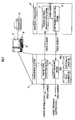
- the compressed solidification manufacturing management system is equipped with a management system 10 and a manufacturing system 20.
- the management system 10 is equipped with a raw material specifying means 11, a memory managing means 12, an issue number database DB1, and a space coordinate database DB2, and the manufacturing system 20 is equipped with a baking material manufacturing means 21 and a compressing-solidifying means 22.
- each processing means 11, 12, DB1, and DB2 are configured by a hardware such as a CPU, a ROM, a RAM and the like, and these processing means may be configured from a common hardware, or a part of or all of these processing means may be configured from different hardware.
- the management system 10 is connected with a keyboard 15 and a mouse 16 as an operating means, and is equipped with a display 17 as a displaying means and a printer 18 as an outputting means.
- the raw material specifying means 11 specifies an introduction date a raw material is introduced to a final disposal site, and classification, weight and consigner of an inorganic waste. Specifically, the raw material specifying means 11 specifies the consigner (an emitter) and the classification of the inorganic waste, from a consigner certificate upon introducing an incineration ash, a melt-solidification product (a meltslug) incinerated by an incinerating facility of a municipality, and the weight of the inorganic waste is specified by weighing at the time of introducing.
- the raw material specifying means 11 issues an issue number accompanying the introduction, and stores the issue number (a manifest number) coordinated with the specified introduction date the raw material is introduced to the final disposal site, the classification, the weight, and the consigner of the inorganic waste, to the issue number database DB1.
- the issue number is a random number without duplicate generated by a random number generator.
- the baking material manufacturing means 21 manufactures a banking material from the inorganic waste managed by the issue number. Specifically, a mixing apparatus (not illustrated) prepares the type-A banking material by mixing type-A inorganic waste, in which concentration of hazardous substances is equal to or less than a predetermined reference value, with added cement and water, and also prepares the type-B banking material by mixing type-B inorganic waste, in which concentration of hazardous substances exceeds the predetermined reference value, with added cement and water.
- the manufactured type-A banking material and type-B banking material are specified and managed by the issued number.
- the type-A inorganic waste may be waste with various concentrations of hazardous substances which are each equal to or less than a given reference value, but may also be waste with a concentration of hazardous substances that is simply less than that of the B-type inorganic waste (irrespective of a reference value).
- the compressing-solidifying means 22 manufactures a compressed solidification using the type-A banking material and the type-B baking material (both managed by the issue number) manufactured by the baking material manufacturing means 21. Specifically, a fill demarcated space is formed by demarcating by walls, and the type-A banking material is set and compressed so as to surround the type-B banking material in the fill demarcated space.
- the memory managing means 12 makes the issue number database DB1 memorize various information coordinated with the issue number issued by the raw material specifying means 11, and manages (inputs/outputs) the information.
- the memory managing means 12 makes the space coordinate database DB2 memorize information on the type-A banking material and the type-B banking material compressed and solidified to the fill demarcation by a compressing-solidifying means 22 for each coordinate space, and manages (inputs/outputs) the information.
- the issue number database DB1 is a memory means which memorizes and manages the issue number issued by the raw material specifying means 11, and memorizes, in coordination with one issue number, the introduction date a raw material is introduced to the final disposal site, and classification, weight and consigner of the inorganic waste. Further, the manufacturing date of the type-A banking material and the type-B banking material managed uniformly with the identical issue number, the used date when the type-A banking material or the type-B banking material is used, and the space coordinate corresponding to the fill demarcation of the compressed solidification manufactured by such use, are memorized coordinated with the issue number.
- the space coordinate database DB2 memorizes and manages, for the coordinate space preliminarily demarcated three-dimensionally with respect to the fill space of the final disposal site, information concerning the actual fill demarcated space corresponding to each coordinate space, for each coordinate space.
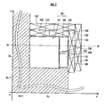
- FIG. 2 shows a look of a plain demarcation (X-Y coordinate space) for an eighth layer of the fill space of the final disposal site with fifteen-layer structure in a vertical direction (Z direction).
- shaded portion indicates the fill demarcated space in which the formation of the compressed solidification has been completed
- a blank portion indicates the fill demarcated space in which the formation of the compressed solidification will be performed hereafter.
- the space coordinate database DB2 memorizes and manages, for each coordinate space, as information of the type-A banking material and the type-B banking material compressed and solidified in the actual fill demarcated space corresponding to each coordinate space, the introduction date the raw material is introduced to the final disposal site, and classification, weight and consigner of the inorganic waste specified by the raw material specifying means 11, the issue number issued by the raw material specifying means 11, the manufacturing date and weight of the type-A banking material and the type-B banking material manufactured by the banking material manufacturing means 21 and coordinated by the issue number, and the used date when the type-A banking material or the type-B banking material is used by the compressing-solidifying means 22 and coordinated by the issue number.
- the demarcation in which the banking material containing the inorganic waste is filled is the actual fill demarcated space corresponded to the coordinate space managed by the space coordinate database DB2, and can be defined as a fill direction X and a fill direction Y orthogonal to the fill direction X in the same plane, and once filling in the same plane is finished, can be expanded by defining a next plane in the height direction Z.
- the compressing-solidifying means 22 divides the divisions (Xn, Yn) on a level Zn by walls to form a fill space Wn, and the fill space Wn is demarcated in the horizontal direction to form a first space 101 and a second space 102 (preprocessing step).
- the fill space Wn is first formed by the walls of already-filled adjacent divisions (Xn, Yn-1) and (Xn-1, Yn), and walls formed by standing up a metal plate 150 onto temporary dams 100, as illustrated in FIG. 3 .
- the temporary dams 100 and the metal plate 150 are disposed for the fill direction X, while the temporary dams 100' and the metal plate 150' are disposed for the orthogonal direction Y.
- compressing-solidifying means 22 disposes an internal partitioning temporary dams 200 in the fill direction X of the fill space Wn and stands up a partitioning metal plate 250 thereon, thereby making the fill space Wn to the second space 102 where the internal partitioning temporary dams 200 are disposed, and the remaining first space 101.
- FIG. 4(A) illustrates how the fill space Wn is partitioned into the first space 101 and the second space 102 by the partitioning metal plate 250 in this way.
- the internal partitioning temporary dams 200 have a tapered face in which the face adjoining the partitioning metal plate 250 becomes narrower proceeding from top to bottom.
- the compressing-solidifying means 22 forms a first compressed solidification part 110 by pouring and compressing the type-B banking material manufactured by the banking material manufacturing element into a first space 101 (first step).
- the first compressed solidification part 110 is formed by pouring the type-B banking material, and setting and compressing the poured type-B banking material, while leaving constant upper spaces 101a and 101b at the top of the first space 101.
- the compressing-solidifying means 22 forms a second compressed solidification part 120 by pouring and compressing the type-A banking material into an upper space 101 a over the first compressed solidification part 110 (second step).
- the second compressed solidification part 120 is formed by pouring the type-A banking material manufactured by the banking material manufacturing means 21 into the upper space 101 a over the first compressed solidification part 110 (leaving the upper space 101b), and then setting and compressing the poured type-A banking material.
- the type-B banking material it is preferable to not have the type-B banking material and the type-A banking material come into direct contact, by evenly spreading and setting fresh gravel over the first compressed solidification part 110 before pouring the type-A banking material. This also exhibits a shielding effect due to the gravel in the case where the type-B banking material contains radioactive substances.
- FIG. 4(B) illustrates how the first compressed solidification part 110 and the second compressed solidification part 120 are formed in the first space 101 in this way.
- the compressing-solidifying means 22 removes the partition between the first space 101 and the second space 102 is removed, and a third compressed solidification part 130 is formed by pouring and compressing the type-A banking material manufactured by the banking material manufacturing means 21 into the second space 102 (third step).
- the compressing-solidifying means 22 forms the third compressed solidification part 130 by pouring the type-A banking material, and then setting and compressing the poured type-A banking material, while leaving the constant upper space 101b at the top of the second space 102.
- the type-A banking material is poured and set such that the surface of the third compressed solidification part 130 becomes continuous with the second compressed solidification part 120.
- FIG. 4(C) illustrates how the third compressed solidification part 130 is formed in the second space 102 in this way.
- the compressing-solidifying means 22 shields the top surface of the second compressed solidification part 120 and the third compressed solidification part 130 (fourth step).
- an upper primary shield layer is formed by evenly spreading and compressing fresh gravel over the second compressed solidification part 120 and the third compressed solidification part 130 (in the upper space 101b).
- an upper capping layer is formed by evenly spreading a covering material consisting of a cement mixture (mortar, for example), and then evenly spreading and compressing gravel onto the evenly spread covering material.
- an upper secondary shield layer is formed by evenly spreading the gravel over the upper capping layer.
- the upper primary shield layer, the upper capping layer, and the upper secondary shield layer are integrated by spreading a cover metal plate (not illustrated) so as to cover the entire top surface, placing a weight (not illustrated) on the cover metal plate, and allowing a curing period to elapse.
- a cover metal plate (not illustrated) so as to cover the entire top surface
- a weight (not illustrated) on the cover metal plate
- FIG. 4(D) illustrates the upper shield structure 140 obtained as a result.
- the compressing-solidifying means 22 shields a lateral face of the third compressed solidification part 130 that is exposed by removing a lateral wall in the fill direction X (fifth step).
- a lateral primary shield layer is formed by applying a coating (a highly waterproof building exterior coating, such as an epoxy resin undercoating, for example) to the exposed lateral face of the third compressed solidification part 130.
- a lateral capping layer is formed by applying a thick coating (a highly waterproof building exterior coating, such as a thick plastic emulsion finishing coat material, for example) to the lateral primary shield layer.
- a lateral secondary shield layer (not illustrated) is formed by applying a coating (a highly waterproof building exterior coating, such as an epoxy resin finish coating, for example) to the lateral capping layer.
- the lateral primary shield layer, the lateral capping layer, and the lateral secondary shield layer after first grouting the depressions with covering material in advance.
- one compressed solidification (a concrete solidified product) is formed by demarcating the actual fill demarcated space corresponding to the coordinate space by walls, and compressing and solidifying the type-A banking material or the type-B banking material in the demarcation, it becomes possible to clearly distinguish the compressed solidification of the adjacent fill demarcated space, and it becomes possible to manufacture the compressed solidification so as to be capable of specifying the same afterwards, both physically and in corresponding relationship with the demarcated space.
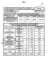
- Fig. 5 shows information of the compressed solidification compressed and solidified in the actual fill demarcated space corresponding to the coordinate space 8-14-10.
- the coordinate space number 10A is indicated on upper right, and as basic information of the coordinate space 8-14-10, a demarcation area, a demarcation volume and the like are displayed therebelow.
- the space coordinate database DB2 memorizes and manages, for each coordinate space, (1) the introduction date the raw material is introduced to the final disposal site, and classification, weight and consigner of the inorganic waste, that are specified by the raw material specifying means 11, (2) the manufacturing date and the weight of the type-A banking material and the type-B banking material that are manufactured by the baking material manufacturing means 21, and (3) the used date when the type-A banking material or the type-B banking material is used by the compressing-solidifying means 22, coordinated with the issue number.
- the recycle treatment certificate (treatment certification) is not output before completing formation of the compressed solidification in the fill demarcated space by the compressing-solidifying means 22, since coordination to the coordinate space is not performed, until the used date of the type-A banking material or the type-B banking material by the compressing-solidifying means 22 is input.
- the compressed solidification manufacturing management system of the present embodiment it becomes possible to manufacture the compressed solidification obtained by filling the banking material including the inorganic waste so as to be capable of specifying the same afterwards, so that it becomes possible to track and manage every record of the manufactured compressed solidification, and consequently improve reliability with respect to the emitter.
- the issue number is issued at the time of introduction of the inorganic waste to the final disposal site by the raw material specifying means.
- the present invention is not limited thereto.
- issuance of the issue number may be omitted, and management may be performed using a waste information acquired from the consigner, or an identification number or an identification code specified by the consigner for each waste.
Landscapes
- Engineering & Computer Science (AREA)
- Environmental & Geological Engineering (AREA)
- Processing Of Solid Wastes (AREA)
Abstract
Description
- The present invention relates to a compressed solidification manufacturing management system which manufactures and manages a compressed solidification obtained by filling a banking material containing an inorganic waste in a final disposal site.
- Conventionally, as a fill management system of waste at a final disposal site of this type, there are known ones in which coordinates are allocated two-dimensionally to a final disposal site preliminarily, a waste is dumped in the two-dimensional coordinate position by a hopper crane, and waste information is coordinated to the coordinate position and is memorized.
- Patent Literature 1: Japanese Patent No.
3786870 - However, in such fill management system of the waste at the final disposal site, the coordinate position is a virtual one, and there is no demarcation in the actual final disposal site. Therefore, at an adjacent region of the coordinate position, it was not clear as to which coordinate position the waste was intended to be dumped.
- Further, as it is apparent from the fact that the hopper crane repeatedly performs dumping of the waste to identical coordinate position, various wastes are piled up in a vertical direction, and it was also not clear at the adjacent region as to which dumping frequency the waste was intended to be dumped.
- In view of the above-mentioned circumstances, the present invention aims at providing a compressed solidification manufacturing management system, which is capable of manufacturing a compressed solidification which is obtained by filling a banking material containing an inorganic waste so as to be capable of specifying the same afterwards, capable of tracking and managing all history of the manufactured compressed solidification, and consequently improving reliability with respect to an emitter.
- A compressed solidification manufacturing management system according to a first aspect of the invention is a compressed solidification manufacturing management system which manufactures and manages a compressed solidification obtained by filling in banking material containing inorganic waste at a final disposal site, characterized by comprising:
- a raw material specifying means which specifies a type, weight and consigner of the inorganic waste introduced into the final disposal site;
- a banking material manufacturing means which manufactures, according to the type of the inorganic waste specified by the raw material specifying means, a type-A banking material prepared by kneading a cement and water with a type-A inorganic waste in which a hazardous material concentration is equal to or less than a predetermined reference value, or a type-B banking material prepared by kneading the cement and water with a type-B inorganic waste in which the hazardous material concentration exceeds the predetermined reference value;
- a compressing-solidifying means which forms the compressed solidification, after demarcating by walls an actual fill demarcated space corresponding to a coordinate space preliminarily partitioned three-dimensionally with respect to fill space of the final disposal site, and providing a first space and a second space by partitioning the fill demarcated space in a horizontal direction, by forming a first compressed solidification part by pouring and compressing the type-B banking material in the first space, by forming a second compressed solidification part by pouring and compressing the type-A banking material on top of the first compressed solidification part, and forming a third compressed solidification part by removing the partition between the first space and the second space in a state where the first compressed solidification part and the second compressed solidification part are formed, and pouring and compressing the type-A banking material in the second space; and
- a memory managing means which memorizes and manages, as information of the type-A banking material and the type-B banking material compressed and solidified in the fill demarcated space by the compressing-solidifying means, the type, the weight and the consigner of the inorganic waste specified by the raw material specifying means, a manufacturing date and a weight of the type-A banking material or the type-B banking material manufactured by the banking material manufacturing means, and a used date on which the type-A banking material or the type-B banking material is used by the compressing-solidifying means, that are coordinated to each coordinate space;
- wherein the memory managing means issues a treatment certification displaying the coordinate space to the consigner, after completion of the formation of the compressed solidification in the fill demarcated space by the compressing-solidifying means.
- According to the compressed solidification manufacturing management system of the first aspect of the invention, as an intermediate treatment of the inorganic waste, the type-A banking material or the type-B baking material as a recycle material may be manufactured from the inorganic waste. Further, by preparing the inorganic waste as the type-A banking material or the type-B banking material, it becomes possible to compress and solidify the same in the fill demarcation demarcated by walls, so as to form one compressed solidification (concrete solidified product), and to clearly distinguish the compressed solidification of the adjacent fill demarcated space.
- By corresponding the actual fill demarcated space with the coordinate space preliminarily partitioned three-dimensionally with respect to the fill space of the final disposal site, it becomes possible to manufacture and manage each one of the compressed solidification so as to be capable of specifying the same afterwards on the three-dimensional coordinate space.
- Further, by coordinating, to the three-dimensional coordinate space, the type, the weight, and the consigner of the inorganic waste specified by the raw material specifying means, the manufacturing date and the weight of the type-A banking material or the type-B banking material manufactured by the banking material manufacturing means, and the used date when the type-A banking material or the type-B banking material is used by the compressing-solidifying means, it becomes possible to manage each one of the compressed solidification, and also to certify treatment with respect to the consigner (for example, an emitter of the inorganic waste).
- At this time, by issuing the treatment certification displaying the coordinate space to the consigner, after completion of the formation of the compressed solidification at the fill demarcated space by the compressing-solidifying means, it becomes possible to certify that it is in the sate where all history of the manufactured compressed solidification may be tracked and managed.
- As such, according to the compressed solidification manufacturing management system of the first aspect of the invention, it becomes possible to manufacture the compressed solidification obtained by filling the banking material including the inorganic waste so as to be capable of specifying the same afterwards, so that it becomes possible to track and manage every record of the manufactured compressed solidification, and consequently improve reliability with respect to the emitter.
- Herein, hazardous substances includes hazardous substances (dioxins) and heavy metals found in the incinerated ash of typical waste such as kitchen waste and disposable plastic, as well as radioactive substances, and are differentiated into type-A inorganic waste and type-B inorganic waste according to whether or not a reference value for any one concentration (such as an amount of radioactivity equal to 100 Bq/kg for radioactive substances, for example) is exceeded.
- The compressed solidification manufacturing management system of a second aspect of the invention is, in the first aspect of the invention,
the raw material specifying means specifies the type, the weight, and the consigner of the inorganic waste introduced into the final disposal site, and issues an issue number accompanying the introduction, and
the memory managing means memorizes and manages, as information of the type-A banking material and the type-B banking material compressed and solidified in the fill demarcation space by the compressing-solidifying means, the issue number issued by the raw material specifying means, that is coordinated to each coordinate space, and display the issue number together with the coordinate space in the treatment certification. - According to the compressed solidification manufacturing management system of the second aspect of the invention, by issuing the issue number (so-called manifest number) when the inorganic waste is introduceed into the final disposal site, and by coordinating the issue number and the three-dimensional coordinate space by the raw material specifying means, it becomes possible to specify afterwards the compressed solidification which is compressed and solidified using the inorganic waste as the banking material from the issue number.
- Further, by displaying the issue number in addition to the coordinate space in the treatment certification, it becomes possible to certify that all history of the manufactured compressed solidification is in the state of being coordinated and traced with the issue number.
- As is explained above, according to the compressed solidification manufacturing management system of the second aspect of the invention, it becomes possible to further improve the reliability with respect to the emitter, by manufacturing the compressed solidification to be able to specify the same afterwards by coordinating with the issue number, and also by being able to trace and manage all history of the manufactured compressed solidification from the issue number.
-
-
FIG. 1 is an overall configuration diagram illustrating a compressed solidification manufacturing management system of the present embodiment; -
FIG. 2 is an explanatory diagram illustrating a coordinate space demarcating three-dimensionally a fill space of a final disposal site; -
FIG. 3 is an explanatory diagram illustrating an actual fill demarcated space coordinated to the coordinate space; -
FIG. 4 is an explanatory diagram illustrating manufacturing process of the compressed solidification by a compressing-solidifying means; -
FIG. 5 is an explanatory diagram illustrating a managing state of the compressed solidification by the coordinate space; and -
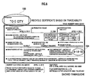
FIG. 6 is an explanatory diagram illustrating a managing state of the compressed solidification by a treatment certification. - A compressed solidification manufacturing management system will now be described as an exemplary embodiment of the present invention.
- As is shown in
FIG. 1 , the compressed solidification manufacturing management system is equipped with amanagement system 10 and amanufacturing system 20. - The
management system 10 is equipped with a raw material specifying means 11, a memory managing means 12, an issue number database DB1, and a space coordinate database DB2, and themanufacturing system 20 is equipped with a baking material manufacturing means 21 and a compressing-solidifying means 22. - In the present embodiment, each processing means 11, 12, DB1, and DB2 are configured by a hardware such as a CPU, a ROM, a RAM and the like, and these processing means may be configured from a common hardware, or a part of or all of these processing means may be configured from different hardware.
- Further, the
management system 10 is connected with akeyboard 15 and amouse 16 as an operating means, and is equipped with adisplay 17 as a displaying means and aprinter 18 as an outputting means. - The raw material specifying means 11 specifies an introduction date a raw material is introduced to a final disposal site, and classification, weight and consigner of an inorganic waste. Specifically, the raw material specifying means 11 specifies the consigner (an emitter) and the classification of the inorganic waste, from a consigner certificate upon introducing an incineration ash, a melt-solidification product (a meltslug) incinerated by an incinerating facility of a municipality, and the weight of the inorganic waste is specified by weighing at the time of introducing.
- Further, the raw material specifying means 11 issues an issue number accompanying the introduction, and stores the issue number (a manifest number) coordinated with the specified introduction date the raw material is introduced to the final disposal site, the classification, the weight, and the consigner of the inorganic waste, to the issue number database DB1. The issue number is a random number without duplicate generated by a random number generator.
- Explanation of the memory managing means 12, the issue number database DB1, and a space coordinate database DB2 will be postponed.
- The baking material manufacturing means 21 manufactures a banking material from the inorganic waste managed by the issue number. Specifically, a mixing apparatus (not illustrated) prepares the type-A banking material by mixing type-A inorganic waste, in which concentration of hazardous substances is equal to or less than a predetermined reference value, with added cement and water, and also prepares the type-B banking material by mixing type-B inorganic waste, in which concentration of hazardous substances exceeds the predetermined reference value, with added cement and water. The manufactured type-A banking material and type-B banking material are specified and managed by the issued number.
- In the present embodiment, the type-A inorganic waste may be waste with various concentrations of hazardous substances which are each equal to or less than a given reference value, but may also be waste with a concentration of hazardous substances that is simply less than that of the B-type inorganic waste (irrespective of a reference value).
- The compressing-solidifying means 22 manufactures a compressed solidification using the type-A banking material and the type-B baking material (both managed by the issue number) manufactured by the baking material manufacturing means 21. Specifically, a fill demarcated space is formed by demarcating by walls, and the type-A banking material is set and compressed so as to surround the type-B banking material in the fill demarcated space.
- The manufacturing of the compressed solidification by the compressing-solidifying means 22 will be explained later with reference to
FIG. 3 andFIG. 4 . - Next, the postponed explanation of the memory managing means 12, the issue number database DB1, and the space coordinate database DB2 will be explained.
- The memory managing means 12 makes the issue number database DB1 memorize various information coordinated with the issue number issued by the raw
material specifying means 11, and manages (inputs/outputs) the information. - Further, the memory managing means 12 makes the space coordinate database DB2 memorize information on the type-A banking material and the type-B banking material compressed and solidified to the fill demarcation by a compressing-solidifying means 22 for each coordinate space, and manages (inputs/outputs) the information.
- The issue number database DB1 is a memory means which memorizes and manages the issue number issued by the raw
material specifying means 11, and memorizes, in coordination with one issue number, the introduction date a raw material is introduced to the final disposal site, and classification, weight and consigner of the inorganic waste. Further, the manufacturing date of the type-A banking material and the type-B banking material managed uniformly with the identical issue number, the used date when the type-A banking material or the type-B banking material is used, and the space coordinate corresponding to the fill demarcation of the compressed solidification manufactured by such use, are memorized coordinated with the issue number. - As is shown in
FIG. 2 , the space coordinate database DB2 memorizes and manages, for the coordinate space preliminarily demarcated three-dimensionally with respect to the fill space of the final disposal site, information concerning the actual fill demarcated space corresponding to each coordinate space, for each coordinate space. -
FIG. 2 shows a look of a plain demarcation (X-Y coordinate space) for an eighth layer of the fill space of the final disposal site with fifteen-layer structure in a vertical direction (Z direction). InFIG. 2 , shaded portion indicates the fill demarcated space in which the formation of the compressed solidification has been completed, and a blank portion indicates the fill demarcated space in which the formation of the compressed solidification will be performed hereafter. - Specifically, the space coordinate database DB2 memorizes and manages, for each coordinate space, as information of the type-A banking material and the type-B banking material compressed and solidified in the actual fill demarcated space corresponding to each coordinate space, the introduction date the raw material is introduced to the final disposal site, and classification, weight and consigner of the inorganic waste specified by the raw
material specifying means 11, the issue number issued by the rawmaterial specifying means 11, the manufacturing date and weight of the type-A banking material and the type-B banking material manufactured by the banking material manufacturing means 21 and coordinated by the issue number, and the used date when the type-A banking material or the type-B banking material is used by the compressing-solidifying means 22 and coordinated by the issue number. - Next, the postponed explanation of the manufacturing of the compressed solidification by the compressing-solidifying
means 22 will be explained with reference toFIG. 3 andFIG. 4 . - As is shown in
FIG. 3 , in the final disposal site, the demarcation in which the banking material containing the inorganic waste is filled, is the actual fill demarcated space corresponded to the coordinate space managed by the space coordinate database DB2, and can be defined as a fill direction X and a fill direction Y orthogonal to the fill direction X in the same plane, and once filling in the same plane is finished, can be expanded by defining a next plane in the height direction Z. - In the present embodiment, the case of shielding compressed solidifications obtained by filling in banking material containing inorganic waste in divisions (Xn, Yn) on a level Zn will be described hereinafter.
- As illustrated in
FIG. 3 , first, the compressing-solidifyingmeans 22 divides the divisions (Xn, Yn) on a level Zn by walls to form a fill space Wn, and the fill space Wn is demarcated in the horizontal direction to form afirst space 101 and a second space 102 (preprocessing step). - Specifically, in such a preprocessing step, the fill space Wn is first formed by the walls of already-filled adjacent divisions (Xn, Yn-1) and (Xn-1, Yn), and walls formed by standing up a
metal plate 150 ontotemporary dams 100, as illustrated inFIG. 3 . - Note that the
temporary dams 100 and themetal plate 150 are disposed for the fill direction X, while the temporary dams 100' and the metal plate 150' are disposed for the orthogonal direction Y. - Next, compressing-solidifying
means 22 disposes an internal partitioningtemporary dams 200 in the fill direction X of the fill space Wn and stands up apartitioning metal plate 250 thereon, thereby making the fill space Wn to thesecond space 102 where the internal partitioningtemporary dams 200 are disposed, and the remainingfirst space 101. -
FIG. 4(A) illustrates how the fill space Wn is partitioned into thefirst space 101 and thesecond space 102 by the partitioningmetal plate 250 in this way. - Note that the internal partitioning
temporary dams 200 have a tapered face in which the face adjoining the partitioningmetal plate 250 becomes narrower proceeding from top to bottom. - Next, the compressing-solidifying
means 22 forms a firstcompressed solidification part 110 by pouring and compressing the type-B banking material manufactured by the banking material manufacturing element into a first space 101 (first step). - In such a first step, the first
compressed solidification part 110 is formed by pouring the type-B banking material, and setting and compressing the poured type-B banking material, while leaving constantupper spaces 101a and 101b at the top of thefirst space 101. - Next, the compressing-solidifying
means 22 forms a secondcompressed solidification part 120 by pouring and compressing the type-A banking material into anupper space 101 a over the first compressed solidification part 110 (second step). - In such a second step, the second
compressed solidification part 120 is formed by pouring the type-A banking material manufactured by the banking material manufacturing means 21 into theupper space 101 a over the first compressed solidification part 110 (leaving the upper space 101b), and then setting and compressing the poured type-A banking material. - Note that in the second step, it is preferable to not have the type-B banking material and the type-A banking material come into direct contact, by evenly spreading and setting fresh gravel over the first
compressed solidification part 110 before pouring the type-A banking material. This also exhibits a shielding effect due to the gravel in the case where the type-B banking material contains radioactive substances. -
FIG. 4(B) illustrates how the firstcompressed solidification part 110 and the secondcompressed solidification part 120 are formed in thefirst space 101 in this way. - Next, the compressing-solidifying
means 22 removes the partition between thefirst space 101 and thesecond space 102 is removed, and a thirdcompressed solidification part 130 is formed by pouring and compressing the type-A banking material manufactured by the banking material manufacturing means 21 into the second space 102 (third step). - In such a third step, first the internal partitioning
temporary dams 200 are hoisted and eliminated, and next the partitioningmetal plate 250 is removed. At this point, since the internal partitioningtemporary dams 200 have a tapered face in which the face adjoining the partitioningmetal plate 250 becomes narrower proceeding from top to bottom, the high pressure applied to this face during the compression of the firstcompressed solidification part 110 and the secondcompressed solidification part 120 acts to push the internal partitioningtemporary dams 200 upwards. For this reason, the internal partitioningtemporary dams 200 may be easily hoisted up and removed. - Subsequently, the compressing-solidifying
means 22 forms the thirdcompressed solidification part 130 by pouring the type-A banking material, and then setting and compressing the poured type-A banking material, while leaving the constant upper space 101b at the top of thesecond space 102. At this point, the type-A banking material is poured and set such that the surface of the thirdcompressed solidification part 130 becomes continuous with the secondcompressed solidification part 120. -
FIG. 4(C) illustrates how the thirdcompressed solidification part 130 is formed in thesecond space 102 in this way. - Note that a structure in which the first
compressed solidification part 110, the secondcompressed solidification part 120, and the thirdcompressed solidification part 130 are integrated is equivalent to a compressed solidification of the present invention. - Further, preferably, the compressing-solidifying
means 22 shields the top surface of the secondcompressed solidification part 120 and the third compressed solidification part 130 (fourth step). - In such a fourth step, an upper primary shield layer is formed by evenly spreading and compressing fresh gravel over the second
compressed solidification part 120 and the third compressed solidification part 130 (in the upper space 101b). Subsequently, an upper capping layer is formed by evenly spreading a covering material consisting of a cement mixture (mortar, for example), and then evenly spreading and compressing gravel onto the evenly spread covering material. Additionally, an upper secondary shield layer is formed by evenly spreading the gravel over the upper capping layer. - In this state, the upper primary shield layer, the upper capping layer, and the upper secondary shield layer are integrated by spreading a cover metal plate (not illustrated) so as to cover the entire top surface, placing a weight (not illustrated) on the cover metal plate, and allowing a curing period to elapse. At this point, the surface f becomes continuous with the adjacent divisions. Then, after the curing period elapses, the cover metal plate and the weight are removed.
- Then partially enlarged view in
FIG. 4(D) illustrates theupper shield structure 140 obtained as a result. - By forming the
upper shield structure 140 on the top face of the compressed solidifications, contact between inorganic waste and rainwater is completely avoided at the top face of the compressed solidifications. - Further, preferably, the compressing-solidifying
means 22 shields a lateral face of the thirdcompressed solidification part 130 that is exposed by removing a lateral wall in the fill direction X (fifth step). - In such a fifth step, first the
temporary dams 100 in the fill direction X side are hoisted and eliminated, and next themetal plate 150 is removed. Subsequently, a lateral primary shield layer is formed by applying a coating (a highly waterproof building exterior coating, such as an epoxy resin undercoating, for example) to the exposed lateral face of the thirdcompressed solidification part 130. In addition, a lateral capping layer is formed by applying a thick coating (a highly waterproof building exterior coating, such as a thick plastic emulsion finishing coat material, for example) to the lateral primary shield layer. Additionally, a lateral secondary shield layer (not illustrated) is formed by applying a coating (a highly waterproof building exterior coating, such as an epoxy resin finish coating, for example) to the lateral capping layer. - Note that in the case where depressions exist in the exposed lateral face of the third
compressed solidification part 130, it is preferable to form the lateral primary shield layer, the lateral capping layer, and the lateral secondary shield layer after first grouting the depressions with covering material in advance. - In the compressed solidification formed as explained above, one compressed solidification (a concrete solidified product) is formed by demarcating the actual fill demarcated space corresponding to the coordinate space by walls, and compressing and solidifying the type-A banking material or the type-B banking material in the demarcation, it becomes possible to clearly distinguish the compressed solidification of the adjacent fill demarcated space, and it becomes possible to manufacture the compressed solidification so as to be capable of specifying the same afterwards, both physically and in corresponding relationship with the demarcated space.
- The above is the configuration of the compressed solidification manufacturing management system of the present embodiment. In the memory managing means 12 of the compressed solidification manufacturing management system, for the coordinate space memorized and managed by the space coordinate database DB2, for example when a coordinate space 8-14-10 of an eighth layer ((Xn, Yn, Zn) = (14, 10, 8)) as a coordinate
space number 10A indicated by a broken line inFig. 2 , is selected by thekeyboard 15 and themouse 16, information related to the actual fill demarcated space corresponding to the coordinate space 8-14-10 is displayed on thedisplay 17, as is shown inFig. 5 . -
Fig. 5 shows information of the compressed solidification compressed and solidified in the actual fill demarcated space corresponding to the coordinate space 8-14-10. First, the coordinatespace number 10A is indicated on upper right, and as basic information of the coordinate space 8-14-10, a demarcation area, a demarcation volume and the like are displayed therebelow. - Further, as information of the type-A banking material and the type-B banking material compressed and solidified in the coordinate space 8-14-10, all of the type-A banking material and the type-B banking material used by the compressing-solidifying
means 22 is displayed. - At this time, the space coordinate database DB2 memorizes and manages, for each coordinate space, (1) the introduction date the raw material is introduced to the final disposal site, and classification, weight and consigner of the inorganic waste, that are specified by the raw
material specifying means 11, (2) the manufacturing date and the weight of the type-A banking material and the type-B banking material that are manufactured by the baking material manufacturing means 21, and (3) the used date when the type-A banking material or the type-B banking material is used by the compressing-solidifyingmeans 22, coordinated with the issue number. - Therefore, it becomes possible to certify treatment, via the memory managing means 12. That is, when a given
consigner 10B is selected in the display screen inFig. 5 , information of the issue number corresponding thereto is displayed in thedisplay 17 as a recycle certificate (treatment certification), as is shown inFig. 6 . Thereafter, such recycle certificate (treatment certification) may be printed out and output by theprinter 18. - The recycle treatment certificate (treatment certification) is not output before completing formation of the compressed solidification in the fill demarcated space by the compressing-solidifying
means 22, since coordination to the coordinate space is not performed, until the used date of the type-A banking material or the type-B banking material by the compressing-solidifyingmeans 22 is input. - That is, it becomes possible to issue the recycle treatment certificate (treatment certification) to the consigner, after completion of the forming of the compressed solidification in the fill demarcated space by the compressing-solidifying
means 22. By doing so, it becomes possible to establish that it is in the state of being able to track and manage every record of the manufactured compressed solidification. - As explained above, according to the compressed solidification manufacturing management system of the present embodiment, it becomes possible to manufacture the compressed solidification obtained by filling the banking material including the inorganic waste so as to be capable of specifying the same afterwards, so that it becomes possible to track and manage every record of the manufactured compressed solidification, and consequently improve reliability with respect to the emitter.
- In the compressed solidification manufacturing management system of the present embodiment, explanation has been given on the case where the issue number is issued at the time of introduction of the inorganic waste to the final disposal site by the raw material specifying means. However, the present invention is not limited thereto. For example, issuance of the issue number may be omitted, and management may be performed using a waste information acquired from the consigner, or an identification number or an identification code specified by the consigner for each waste.
-
- 10: Management system (compressed solidification manufacturing management system)
- 11: Raw material specifying means
- 12: Memory managing means
- 20: Manufacturing system (compressed solidification manufacturing management system)
- 21: Banking material manufacturing means
- 22: Compressing-solidifying means,
- 101: First space
- 102: Second space
- 110: First compressed solidification part (compressed solidification)
- 120: Second compressed solidification part (compressed solidification)
- 130: Third compressed solidification part (compressed solidification)
Claims (2)
- A compressed solidification manufacturing management system which manufactures and manages a compressed solidification obtained by filling in banking material containing inorganic waste at a final disposal site, characterized by comprising:a raw material specifying means which specifies a type, weight and consigner of the inorganic waste introduced into the final disposal site;a banking material manufacturing means which manufactures, according to the type of the inorganic waste specified by the raw material specifying means, a type-A banking material prepared by kneading a cement and water with a type-A inorganic waste in which a hazardous material concentration is equal to or less than a predetermined reference value, or a type-B banking material prepared by kneading the cement and water with a type-B inorganic waste in which the hazardous material concentration exceeds the predetermined reference value;a compressing-solidifying means which forms the compressed solidification, after demarcating by walls an actual fill demarcated space corresponding to a coordinate space preliminarily partitioned three-dimensionally with respect to fill space of the final disposal site, and providing a first space and a second space by partitioning the fill demarcated space in a horizontal direction, by forming a first compressed solidification part by pouring and compressing the type-B banking material in the first space, by forming a second compressed solidification part by pouring and compressing the type-A banking material on top of the first compressed solidification part, and by forming a third compressed solidification part by removing the partition between the first space and the second space in a state where the first compressed solidification part and the second compressed solidification part are formed, and pouring and compressing the type-A banking material in the second space; anda memory managing means which memorizes and manages, as information of the type-A banking material and the type-B banking material compressed and solidified in the fill demarcated space by the compressing-solidifying means, the type, the weight and the consigner of the inorganic waste specified by the raw material specifying means, a manufacturing date and a weight of the type-A banking material or the type-B banking material manufactured by the banking material manufacturing means, and a used date on which the type-A banking material or the type-B banking material is used by the compressing-solidifying means, that are coordinated to each coordinate space;wherein the memory managing means issues a treatment certification displaying the coordinate space to the consigner, after completion of the formation of the compressed solidification in the fill demarcated space by the compressing-solidifying means.
- The compressed solidification manufacturing management system according to Claim 1,
wherein the raw material specifying means specifies the type, the weight, and the consigner of the inorganic waste introduced into the final disposal site, and issues an issue number accompanying the introduction, and
the memory managing means memorizes and manages, as information of the type-A banking material and the type-B banking material compressed and solidified in the fill demarcation space by the compressing-solidifying means, the issue number issued by the raw material specifying means, that is coordinated to each coordinate space, and display the issue number together with the coordinate space in the treatment certification.
Applications Claiming Priority (2)
| Application Number | Priority Date | Filing Date | Title |
|---|---|---|---|
| JP2012247886 | 2012-11-09 | ||
| PCT/JP2012/082691 WO2013085077A1 (en) | 2012-11-09 | 2012-12-17 | Management system for manufacturing compacted molded body |
Publications (3)
| Publication Number | Publication Date |
|---|---|
| EP2644286A1 true EP2644286A1 (en) | 2013-10-02 |
| EP2644286A4 EP2644286A4 (en) | 2015-03-11 |
| EP2644286B1 EP2644286B1 (en) | 2016-08-17 |
Family
ID=48574422
Family Applications (1)
| Application Number | Title | Priority Date | Filing Date |
|---|---|---|---|
| EP12854831.0A Active EP2644286B1 (en) | 2012-11-09 | 2012-12-17 | Method for manufacturing compacted molded body |
Country Status (3)
| Country | Link |
|---|---|
| EP (1) | EP2644286B1 (en) |
| JP (1) | JP5380631B1 (en) |
| WO (1) | WO2013085077A1 (en) |
Family Cites Families (8)
| Publication number | Priority date | Publication date | Assignee | Title |
|---|---|---|---|---|
| JP2002109154A (en) * | 2000-09-29 | 2002-04-12 | Sumitomo Metal Ind Ltd | Waste final disposal site management system |
| JP2001184427A (en) * | 2000-11-07 | 2001-07-06 | Mitsubishi Electric Corp | Emission and waste treatment management system |
| JP3786870B2 (en) | 2001-12-25 | 2006-06-14 | 株式会社建設工学研究社 | Landfill management method and system in final disposal site for coated waste |
| JP4511277B2 (en) * | 2004-08-11 | 2010-07-28 | 株式会社間組 | Landfill management system for waste final disposal site |
| JP5085945B2 (en) * | 2007-01-19 | 2012-11-28 | 株式会社とわに | Disposal of granular waste |
| JP2010023020A (en) * | 2008-06-17 | 2010-02-04 | Taisei Kanri Kaihatsu Kk | System for managing waste landfill disposal site |
| JP4317260B1 (en) * | 2009-03-07 | 2009-08-19 | 株式会社フジコーポレーション | Numerous unit solidified molding disposal methods by separating and integrating inorganic waste at the final disposal site and numerous unit solidified molding disposal structures |
| JP4397050B1 (en) * | 2009-04-01 | 2010-01-13 | 株式会社フジコーポレーション | Landfill waste covering structure at final disposal site |
-
2012
- 2012-12-17 EP EP12854831.0A patent/EP2644286B1/en active Active
- 2012-12-17 JP JP2013518027A patent/JP5380631B1/en active Active
- 2012-12-17 WO PCT/JP2012/082691 patent/WO2013085077A1/en not_active Ceased
Also Published As
| Publication number | Publication date |
|---|---|
| JPWO2013085077A1 (en) | 2015-04-27 |
| JP5380631B1 (en) | 2014-01-08 |
| EP2644286A4 (en) | 2015-03-11 |
| WO2013085077A1 (en) | 2013-06-13 |
| EP2644286B1 (en) | 2016-08-17 |
Similar Documents
| Publication | Publication Date | Title |
|---|---|---|
| Bakchan et al. | Seven-dimensional automated construction waste quantification and management framework: Integration with project and site planning | |
| JP6902180B2 (en) | Casting management system, casting management method and casting management program | |
| CN101718644B (en) | Method for manufacturing direct shear test structural plane model | |
| US6682684B1 (en) | Procedures for rapid build and improved surface characteristics in layered manufacture | |
| Liu et al. | BIM-based integrated framework for detailed cost estimation and schedule planning of construction projects | |
| JP6890796B2 (en) | Casting management system, casting management method and casting management program | |
| US20220274166A1 (en) | Powder packing methods and apparatus | |
| Mazzucco et al. | Numerical modelling of ellipsoidal inclusions | |
| Perko et al. | Decalcification of cracked cement structures | |
| EP2620231B1 (en) | Inorganic waste solid shield structure and method for manufacturing inorganic waste solid shield structure | |
| Faghirinejadfard et al. | Economic comparison of industrialized building system and conventional construction system using building information modeling | |
| Jesus et al. | The potential of 3D printing in building pathology: rehabilitation of cultural heritage | |
| EP2644286B1 (en) | Method for manufacturing compacted molded body | |
| Bakchan et al. | BIM-based estimation of wood waste stream: The case of an institutional building project | |
| Seigneur et al. | Transport properties evolution of cement model system under degradation-Incorporation of a pore-scale approach into reactive transport modelling | |
| KR102112747B1 (en) | Method for planning of construction management using vertical relation and horizontal relation and program and computer readable media thereof | |
| KR102112749B1 (en) | Method for managing of the tower crane using construction management plan and computer readable media thereof | |
| Brückner et al. | How to develop a BIM-workflow for landscape architecture: A practical approach | |
| JP3189378U (en) | Compacted compact manufacturing management system | |
| Shenkman et al. | Advantages of using BIM (BIM-technology) for the design and construction of subsoil use industry buildings and structures | |
| JP2025155126A (en) | Pouring management system and pouring management method | |
| Williams et al. | Use of multiscale particle simulations in the design of nuclear plant decommissioning | |
| Çelik et al. | Modeling and production of solid model of south panel, Tuncbilek open pit by 3D printer | |
| JP7429253B2 (en) | Concrete placement management device, concrete placement management method, and concrete placement management program | |
| Adi et al. | Modeling and Detailing Railway Bridge Structure Using Allplan Engineering |
Legal Events
| Date | Code | Title | Description |
|---|---|---|---|
| PUAI | Public reference made under article 153(3) epc to a published international application that has entered the european phase |
Free format text: ORIGINAL CODE: 0009012 |
|
| 17P | Request for examination filed |
Effective date: 20130624 |
|
| AK | Designated contracting states |
Kind code of ref document: A1 Designated state(s): AL AT BE BG CH CY CZ DE DK EE ES FI FR GB GR HR HU IE IS IT LI LT LU LV MC MK MT NL NO PL PT RO RS SE SI SK SM TR |
|
| RIN1 | Information on inventor provided before grant (corrected) |
Inventor name: YAMAGUCHI, TOKICHIRO |
|
| A4 | Supplementary search report drawn up and despatched |
Effective date: 20150206 |
|
| RIC1 | Information provided on ipc code assigned before grant |
Ipc: B09B 5/00 20060101ALI20150202BHEP Ipc: B09B 1/00 20060101AFI20150202BHEP |
|
| 17Q | First examination report despatched |
Effective date: 20150729 |
|
| DAX | Request for extension of the european patent (deleted) | ||
| GRAP | Despatch of communication of intention to grant a patent |
Free format text: ORIGINAL CODE: EPIDOSNIGR1 |
|
| INTG | Intention to grant announced |
Effective date: 20160422 |
|
| GRAS | Grant fee paid |
Free format text: ORIGINAL CODE: EPIDOSNIGR3 |
|
| GRAA | (expected) grant |
Free format text: ORIGINAL CODE: 0009210 |
|
| AK | Designated contracting states |
Kind code of ref document: B1 Designated state(s): AL AT BE BG CH CY CZ DE DK EE ES FI FR GB GR HR HU IE IS IT LI LT LU LV MC MK MT NL NO PL PT RO RS SE SI SK SM TR |
|
| REG | Reference to a national code |
Ref country code: GB Ref legal event code: FG4D |
|
| REG | Reference to a national code |
Ref country code: CH Ref legal event code: EP |
|
| REG | Reference to a national code |
Ref country code: IE Ref legal event code: FG4D |
|
| REG | Reference to a national code |
Ref country code: AT Ref legal event code: REF Ref document number: 820560 Country of ref document: AT Kind code of ref document: T Effective date: 20160915 |
|
| REG | Reference to a national code |
Ref country code: NL Ref legal event code: FP |
|
| REG | Reference to a national code |
Ref country code: DE Ref legal event code: R096 Ref document number: 602012022054 Country of ref document: DE |
|
| REG | Reference to a national code |
Ref country code: FR Ref legal event code: PLFP Year of fee payment: 5 |
|
| REG | Reference to a national code |
Ref country code: LT Ref legal event code: MG4D |
|
| REG | Reference to a national code |
Ref country code: AT Ref legal event code: MK05 Ref document number: 820560 Country of ref document: AT Kind code of ref document: T Effective date: 20160817 |
|
| PG25 | Lapsed in a contracting state [announced via postgrant information from national office to epo] |
Ref country code: RS Free format text: LAPSE BECAUSE OF FAILURE TO SUBMIT A TRANSLATION OF THE DESCRIPTION OR TO PAY THE FEE WITHIN THE PRESCRIBED TIME-LIMIT Effective date: 20160817 Ref country code: HR Free format text: LAPSE BECAUSE OF FAILURE TO SUBMIT A TRANSLATION OF THE DESCRIPTION OR TO PAY THE FEE WITHIN THE PRESCRIBED TIME-LIMIT Effective date: 20160817 Ref country code: LT Free format text: LAPSE BECAUSE OF FAILURE TO SUBMIT A TRANSLATION OF THE DESCRIPTION OR TO PAY THE FEE WITHIN THE PRESCRIBED TIME-LIMIT Effective date: 20160817 Ref country code: IT Free format text: LAPSE BECAUSE OF FAILURE TO SUBMIT A TRANSLATION OF THE DESCRIPTION OR TO PAY THE FEE WITHIN THE PRESCRIBED TIME-LIMIT Effective date: 20160817 Ref country code: FI Free format text: LAPSE BECAUSE OF FAILURE TO SUBMIT A TRANSLATION OF THE DESCRIPTION OR TO PAY THE FEE WITHIN THE PRESCRIBED TIME-LIMIT Effective date: 20160817 Ref country code: NO Free format text: LAPSE BECAUSE OF FAILURE TO SUBMIT A TRANSLATION OF THE DESCRIPTION OR TO PAY THE FEE WITHIN THE PRESCRIBED TIME-LIMIT Effective date: 20161117 |
|
| PG25 | Lapsed in a contracting state [announced via postgrant information from national office to epo] |
Ref country code: GR Free format text: LAPSE BECAUSE OF FAILURE TO SUBMIT A TRANSLATION OF THE DESCRIPTION OR TO PAY THE FEE WITHIN THE PRESCRIBED TIME-LIMIT Effective date: 20161118 Ref country code: AT Free format text: LAPSE BECAUSE OF FAILURE TO SUBMIT A TRANSLATION OF THE DESCRIPTION OR TO PAY THE FEE WITHIN THE PRESCRIBED TIME-LIMIT Effective date: 20160817 Ref country code: LV Free format text: LAPSE BECAUSE OF FAILURE TO SUBMIT A TRANSLATION OF THE DESCRIPTION OR TO PAY THE FEE WITHIN THE PRESCRIBED TIME-LIMIT Effective date: 20160817 Ref country code: PL Free format text: LAPSE BECAUSE OF FAILURE TO SUBMIT A TRANSLATION OF THE DESCRIPTION OR TO PAY THE FEE WITHIN THE PRESCRIBED TIME-LIMIT Effective date: 20160817 Ref country code: SE Free format text: LAPSE BECAUSE OF FAILURE TO SUBMIT A TRANSLATION OF THE DESCRIPTION OR TO PAY THE FEE WITHIN THE PRESCRIBED TIME-LIMIT Effective date: 20160817 Ref country code: PT Free format text: LAPSE BECAUSE OF FAILURE TO SUBMIT A TRANSLATION OF THE DESCRIPTION OR TO PAY THE FEE WITHIN THE PRESCRIBED TIME-LIMIT Effective date: 20161219 Ref country code: ES Free format text: LAPSE BECAUSE OF FAILURE TO SUBMIT A TRANSLATION OF THE DESCRIPTION OR TO PAY THE FEE WITHIN THE PRESCRIBED TIME-LIMIT Effective date: 20160817 |
|
| PG25 | Lapsed in a contracting state [announced via postgrant information from national office to epo] |
Ref country code: RO Free format text: LAPSE BECAUSE OF FAILURE TO SUBMIT A TRANSLATION OF THE DESCRIPTION OR TO PAY THE FEE WITHIN THE PRESCRIBED TIME-LIMIT Effective date: 20160817 Ref country code: EE Free format text: LAPSE BECAUSE OF FAILURE TO SUBMIT A TRANSLATION OF THE DESCRIPTION OR TO PAY THE FEE WITHIN THE PRESCRIBED TIME-LIMIT Effective date: 20160817 |
|
| REG | Reference to a national code |
Ref country code: DE Ref legal event code: R097 Ref document number: 602012022054 Country of ref document: DE |
|
| PG25 | Lapsed in a contracting state [announced via postgrant information from national office to epo] |
Ref country code: SM Free format text: LAPSE BECAUSE OF FAILURE TO SUBMIT A TRANSLATION OF THE DESCRIPTION OR TO PAY THE FEE WITHIN THE PRESCRIBED TIME-LIMIT Effective date: 20160817 Ref country code: SK Free format text: LAPSE BECAUSE OF FAILURE TO SUBMIT A TRANSLATION OF THE DESCRIPTION OR TO PAY THE FEE WITHIN THE PRESCRIBED TIME-LIMIT Effective date: 20160817 Ref country code: BG Free format text: LAPSE BECAUSE OF FAILURE TO SUBMIT A TRANSLATION OF THE DESCRIPTION OR TO PAY THE FEE WITHIN THE PRESCRIBED TIME-LIMIT Effective date: 20161117 Ref country code: DK Free format text: LAPSE BECAUSE OF FAILURE TO SUBMIT A TRANSLATION OF THE DESCRIPTION OR TO PAY THE FEE WITHIN THE PRESCRIBED TIME-LIMIT Effective date: 20160817 Ref country code: CZ Free format text: LAPSE BECAUSE OF FAILURE TO SUBMIT A TRANSLATION OF THE DESCRIPTION OR TO PAY THE FEE WITHIN THE PRESCRIBED TIME-LIMIT Effective date: 20160817 |
|
| PLBE | No opposition filed within time limit |
Free format text: ORIGINAL CODE: 0009261 |
|
| STAA | Information on the status of an ep patent application or granted ep patent |
Free format text: STATUS: NO OPPOSITION FILED WITHIN TIME LIMIT |
|
| 26N | No opposition filed |
Effective date: 20170518 |
|
| REG | Reference to a national code |
Ref country code: CH Ref legal event code: PL |
|
| GBPC | Gb: european patent ceased through non-payment of renewal fee |
Effective date: 20161217 |
|
| PG25 | Lapsed in a contracting state [announced via postgrant information from national office to epo] |
Ref country code: SI Free format text: LAPSE BECAUSE OF FAILURE TO SUBMIT A TRANSLATION OF THE DESCRIPTION OR TO PAY THE FEE WITHIN THE PRESCRIBED TIME-LIMIT Effective date: 20160817 |
|
| PG25 | Lapsed in a contracting state [announced via postgrant information from national office to epo] |
Ref country code: MC Free format text: LAPSE BECAUSE OF FAILURE TO SUBMIT A TRANSLATION OF THE DESCRIPTION OR TO PAY THE FEE WITHIN THE PRESCRIBED TIME-LIMIT Effective date: 20160817 |
|
| REG | Reference to a national code |
Ref country code: IE Ref legal event code: MM4A |
|
| PG25 | Lapsed in a contracting state [announced via postgrant information from national office to epo] |
Ref country code: LI Free format text: LAPSE BECAUSE OF NON-PAYMENT OF DUE FEES Effective date: 20161231 Ref country code: CH Free format text: LAPSE BECAUSE OF NON-PAYMENT OF DUE FEES Effective date: 20161231 Ref country code: LU Free format text: LAPSE BECAUSE OF NON-PAYMENT OF DUE FEES Effective date: 20161217 |
|
| PG25 | Lapsed in a contracting state [announced via postgrant information from national office to epo] |
Ref country code: GB Free format text: LAPSE BECAUSE OF NON-PAYMENT OF DUE FEES Effective date: 20161217 Ref country code: IE Free format text: LAPSE BECAUSE OF NON-PAYMENT OF DUE FEES Effective date: 20161217 |
|
| REG | Reference to a national code |
Ref country code: FR Ref legal event code: PLFP Year of fee payment: 6 |
|
| PG25 | Lapsed in a contracting state [announced via postgrant information from national office to epo] |
Ref country code: CY Free format text: LAPSE BECAUSE OF FAILURE TO SUBMIT A TRANSLATION OF THE DESCRIPTION OR TO PAY THE FEE WITHIN THE PRESCRIBED TIME-LIMIT Effective date: 20160817 Ref country code: HU Free format text: LAPSE BECAUSE OF FAILURE TO SUBMIT A TRANSLATION OF THE DESCRIPTION OR TO PAY THE FEE WITHIN THE PRESCRIBED TIME-LIMIT; INVALID AB INITIO Effective date: 20121217 |
|
| PG25 | Lapsed in a contracting state [announced via postgrant information from national office to epo] |
Ref country code: MK Free format text: LAPSE BECAUSE OF FAILURE TO SUBMIT A TRANSLATION OF THE DESCRIPTION OR TO PAY THE FEE WITHIN THE PRESCRIBED TIME-LIMIT Effective date: 20160817 Ref country code: IS Free format text: LAPSE BECAUSE OF FAILURE TO SUBMIT A TRANSLATION OF THE DESCRIPTION OR TO PAY THE FEE WITHIN THE PRESCRIBED TIME-LIMIT Effective date: 20160817 |
|
| PG25 | Lapsed in a contracting state [announced via postgrant information from national office to epo] |
Ref country code: MT Free format text: LAPSE BECAUSE OF NON-PAYMENT OF DUE FEES Effective date: 20161217 |
|
| PG25 | Lapsed in a contracting state [announced via postgrant information from national office to epo] |
Ref country code: TR Free format text: LAPSE BECAUSE OF FAILURE TO SUBMIT A TRANSLATION OF THE DESCRIPTION OR TO PAY THE FEE WITHIN THE PRESCRIBED TIME-LIMIT Effective date: 20160817 Ref country code: AL Free format text: LAPSE BECAUSE OF FAILURE TO SUBMIT A TRANSLATION OF THE DESCRIPTION OR TO PAY THE FEE WITHIN THE PRESCRIBED TIME-LIMIT Effective date: 20160817 |
|
| PGFP | Annual fee paid to national office [announced via postgrant information from national office to epo] |
Ref country code: DE Payment date: 20251211 Year of fee payment: 14 |
|
| PGFP | Annual fee paid to national office [announced via postgrant information from national office to epo] |
Ref country code: NL Payment date: 20251219 Year of fee payment: 14 Ref country code: FR Payment date: 20251223 Year of fee payment: 14 |
|
| PGFP | Annual fee paid to national office [announced via postgrant information from national office to epo] |
Ref country code: BE Payment date: 20251219 Year of fee payment: 14 |