EP2644256A1 - Verfahren und Vorrichtung zur wirksamen Kohlendioxiderfassung - Google Patents
Verfahren und Vorrichtung zur wirksamen Kohlendioxiderfassung Download PDFInfo
- Publication number
- EP2644256A1 EP2644256A1 EP12162635.2A EP12162635A EP2644256A1 EP 2644256 A1 EP2644256 A1 EP 2644256A1 EP 12162635 A EP12162635 A EP 12162635A EP 2644256 A1 EP2644256 A1 EP 2644256A1
- Authority
- EP
- European Patent Office
- Prior art keywords
- calciner
- absorbent
- gases
- flue
- carbonator
- Prior art date
- Legal status (The legal status is an assumption and is not a legal conclusion. Google has not performed a legal analysis and makes no representation as to the accuracy of the status listed.)
- Withdrawn
Links
Images

Classifications
-
- B—PERFORMING OPERATIONS; TRANSPORTING
- B01—PHYSICAL OR CHEMICAL PROCESSES OR APPARATUS IN GENERAL
- B01D—SEPARATION
- B01D53/00—Separation of gases or vapours; Recovering vapours of volatile solvents from gases; Chemical or biological purification of waste gases, e.g. engine exhaust gases, smoke, fumes, flue gases, aerosols
- B01D53/34—Chemical or biological purification of waste gases
- B01D53/46—Removing components of defined structure
- B01D53/62—Carbon oxides
-
- Y—GENERAL TAGGING OF NEW TECHNOLOGICAL DEVELOPMENTS; GENERAL TAGGING OF CROSS-SECTIONAL TECHNOLOGIES SPANNING OVER SEVERAL SECTIONS OF THE IPC; TECHNICAL SUBJECTS COVERED BY FORMER USPC CROSS-REFERENCE ART COLLECTIONS [XRACs] AND DIGESTS
- Y02—TECHNOLOGIES OR APPLICATIONS FOR MITIGATION OR ADAPTATION AGAINST CLIMATE CHANGE
- Y02A—TECHNOLOGIES FOR ADAPTATION TO CLIMATE CHANGE
- Y02A50/00—TECHNOLOGIES FOR ADAPTATION TO CLIMATE CHANGE in human health protection, e.g. against extreme weather
- Y02A50/20—Air quality improvement or preservation, e.g. vehicle emission control or emission reduction by using catalytic converters
-
- Y—GENERAL TAGGING OF NEW TECHNOLOGICAL DEVELOPMENTS; GENERAL TAGGING OF CROSS-SECTIONAL TECHNOLOGIES SPANNING OVER SEVERAL SECTIONS OF THE IPC; TECHNICAL SUBJECTS COVERED BY FORMER USPC CROSS-REFERENCE ART COLLECTIONS [XRACs] AND DIGESTS
- Y02—TECHNOLOGIES OR APPLICATIONS FOR MITIGATION OR ADAPTATION AGAINST CLIMATE CHANGE
- Y02C—CAPTURE, STORAGE, SEQUESTRATION OR DISPOSAL OF GREENHOUSE GASES [GHG]
- Y02C20/00—Capture or disposal of greenhouse gases
- Y02C20/40—Capture or disposal of greenhouse gases of CO2
Definitions
- the present disclosure relates to the reduction of carbon dioxide (CO 2 ) emissions from flue gases. More particularly, it relates to an efficient method and apparatus to capture CO 2 from flue gases of a while simultaneously reducing the energy and capital expenditures necessary for CO 2 capture.
- CO 2 carbon dioxide
- Certain processes such as combustion of carbon containing fuels, produce gaseous emissions of CO 2 .
- CO 2 has been identified as a "greenhouse” gas, which appears to contribute to global warming. Because of its status as a “greenhouse” gas, technologies have been developed to prevent large quantities of CO 2 from being released into the atmosphere from the use of fossil fuels. The technologies generally fall into one of three areas: post combustion capture (PCC), where CO 2 is removed after combustion; pre-combustion (PC), where fuel is converted before combustion; and oxy-firing combustion where, fuel is burned in enriched or pure oxygen instead of ambient air.
- PCC post combustion capture
- PC pre-combustion
- oxy-firing combustion where, fuel is burned in enriched or pure oxygen instead of ambient air.
- Methods for PCC removal of CO 2 from existing gas streams include chemical absoiption/adsorption with particular solvent systems, membrane separation, cryogenic fractionation, and/or adsorption using molecular sieves.
- CO 2 can be captured from a flue stream using a CO 2 absorbent by the following reaction: Absorbent + CO 2 --> Carbonated Absorbent (carbonation) - exothermic The absorbent is placed in contact with the flue stream containing CO 2 in a reactor (carbonator), wherein the CO 2 is absorbed, forming a carbonated absorbent.
- the carbonated absorbent may be then heated in a second reactor (calciner), releasing the CO 2 for capture and processing, and regenerating absorbent by the following reaction: Carbonated Absorbent-->Absorbent + CO 2 (calcination) - endothermic
- This process is considered a regenerative process because the absorbent material is, to a large extent, not consumed and may be continually regenerated and cycled through the system.
- US Patent No. 6,737,031 discloses an absorbent looping method employing lime (CaO) as the absorbent wherein the CaO is produced in a circulating fluidized bed hearth which has been injected with calcium carbonate (CaCO 3 ).
- the CaO is used, in part, to capture CO 2 from combustion via carbonation, forming CaCO 3 .
- the CaO may be continually regenerated from the CaCO 3 via calcination.
- a method for carbon dioxide (CO 2 ) capture from flue gases of a gas plant including, transmitting a first portion of the flue gases to a heating surface of a calciner, calcining a carbonated absorbent in the calciner, separating from a flue stream of the calciner an absorbent, transmitting absorbent to a carbonator, transmitting the first portion of the flue gases from the heating surface of the calciner to the carbonator, transmitting a second portion of the flue stream to the carbonator, absorbing CO 2 from the flue gases by placing the flue gases in contact with the absorbent within the carbonator such that carbonated absorbent is formed, separating carbonated absorbent from a flue stream of the carbonator, and transmitting the carbonated absorbent to the calciner.
- CO 2 carbon dioxide
- Heat present in the first portion of the flue stream provides partial heat energy for a calcination reaction in the calciner.
- the first portion of the flue stream is further heated via a first heat exchange with gases exiting the heating surface of the calciner.
- the first portion of the flue stream is further heated by a combustion chamber to acquire temperatures necessary for calcination. Heat is transferred from the first portion of the flue stream to the calciner via the heating surface of the calciner.
- a method to reduce carbon dioxide (CO 2 ) emissions including transferring heat contained in hot off gases to a calciner, calcining a carbonated absorbent in the calciner, transmitting calcinated absorbent from the calciner to a carbonator, transmitting the off gases to the carbonator, and capturing CO 2 from the off gases by placing the off gases in contact with the calcinated absorbent such that carbonation occurs forming carbonated absorbent.
- CO 2 carbon dioxide
- an apparatus for CO 2 capture from flue gases which includes a calciner, a heating element attached to the calciner, a flue stream configured to transmit flue gases to the heating element, and a carbonator configured to receive absorbent from the calciner.
- the heating element is configured to externally transfer heat from the flue gases to the calciner.
- Calcinated absorbent is created via calcination of carbonated absorbent in the calciner. Flue gases are transmitted to the carbonator.
- CO 2 is captured from the flue gases in the carbonator by placing the flue gases in contact with calcinated absorbent.
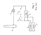
- Figure 1 is a schematic flow diagram of a typical conventional gas plant.
- Figure 2 is a schematic flow diagram of an exemplary embodiment of the present disclosure.
- a method is provided to capture CO 2 from flue gases by transmitting a first portion of flue gases to a calciner and a second portion of flue gases to a carbonator.
- Carbonated CO 2 absorbent is calcinated in the calciner and absorbent is separated from a flue stream of the calciner and transmitted to the carbonator where the absorbent is placed in contact with the flue gases for absorption of CO 2 via carbonation.
- Heat energy required to calcinate the carbonated absorbent in the calciner is provided, in part, by the flue gases, which may be of various temperatures depending upon the plant and/or process the flue gases are generated in.
- the flue gases used to moderate hot side temperatures of the calciner may be further heated via a heat exchange with gases exiting a heating surface of the calciner. Any additional heat necessary to reach sufficient temperatures for calcination may be provided by a combustion chamber.
- the flue gases are then transmitted such that they externally heat the calciner, providing heat for calcination. After heating the calciner, the flue gases are transmitted to the carbonator for CO 2 absorption.
- an apparatus having a calciner, a heating element attached to the calciner, a flue stream configured to transmit to the heating element and a carbonator configured to receive absorbent from the calciner.
- Heat in the flue stream is transferred to the heat element such that the calciner is heated for calcination.
- CO 2 is captured from the flue gases in the carbonator by placing the flue gases in contact with calcinated absorbent formed in the calciner.
- Embodiments of the present disclosure reduce the energy and capital costs of capturing CO 2 from flue gases by exposing CO 2 contained in the flue gases to an absorbent which is created from a calcination process with heat supplied, in part, from the flue gases.
- an absorbent which is created from a calcination process with heat supplied, in part, from the flue gases.
- a calciner By transferring heat from the flue gases to a calciner, ongoing calcination of carbonated absorbent for return as absorbent to a carbonator may be accomplished with reduced energy consumption. Unconditioned temperatures of the flue gases are utilized to avoid unnecessary cooling or heating.
- the flue gases treated by absorbent are reduced in carbon dioxide content suitable for release into the atmosphere and gases from the flue stream of the calciner are primarily CO 2 thereby simplifying the process of capture and storage of the CO 2 .
- embodiments of the present disclosure substantially reduce the energy and capital costs typically associated with CO 2 capture using a CO 2 absorbent.
- Fig. 1 which generally shows a typical conventional gas plant having a gas turbine 14 supplied by a fuel 10 and air 12.
- enriched oxygen gas may be used instead of air.
- Off gases 16 of the gas turbine 14 are transmitted to heat exchanger 18 for heat recovery prior to transmission to a stack 24 and venting to the atmosphere.
- a portion 20 of the off gases 16 may be retuned to the gas turbine 14 which returned portion 20 may be first cooled in a cooler 22, which may be a direct contact cooler.
- off gases 16 will typically have a temperature of about 650°C.
- flue gases 16 from the gas turbine 14 are split, with a first portion 36 being transmitted to first heat exchanger 60 such that first portion 36 is further heated by exit gases 72 leaving a heating surface 70 of a calciner 32.
- the exemplary embodiment shown in Fig. 2 shows flue gases from gas turbine 14, however, flue gases from other combustion plants or industrial processes are contemplated by the present disclosure.
- the flue gases 16 and first portion 36 will typically be approximately 650°C, depending on the combustion plant or industrial process producing the flue gases 16.
- First portion 36 may generally be heated to approximately 850°C via heat exchange in first heat exchanger 60.
- First portion 36 may be further heated via combustion chamber 64 supplied by fuel 66 and air 68.
- Combustion chamber 64 may be a direct fire furnace.
- First portion 36 may be heated by combustion chamber 64 to approximately 1050°C, depending the temperatures required for calcination of the absorbent.
- furnace 64 may be utilized to increase a temperature of first portion 36 by 150°C to 200°C providing sufficient temperature of portion 36 to heat calciner 32 to calcination temperatures.
- first portion 36 may also be heated by flue stream 76 of the calciner 32.
- first portion 36 may be transmitted to heating surface 70 of calciner 32 such that first portion 36 externally provides heat to the calciner 32.
- the calciner 32 is heated to a temperature sufficient to permit calcination of an absorbent within the calciner 32, which may vary depending on the absorbent chosen. For lime/limestone, a target temperature of calciner 32 typically would be above 850°C.
- Heat input from first portion 36 to calciner 32 is indirect via heat surface 70, which may be heat surfaces installed in calciner 32 or alternative indirect heating systems such as rotary kilns or heated bubbling beds.
- combustion chamber 64 may be configured such that calciner 32 is located inside of combustion chamber 64. In the alternative embodiment, combustion chamber 64 may be a gas boiler.
- First portion 36 exits heat surface 70 and transmits back to first exchanger 60. From first exchanger 60, the now partially cooled first portion 72 may be transmitted to a carbonator 28. Optionally, partially cooled first portion 72 may be first transmitted to second heat exchanger 74 to recover heat for steam production prior to transmission to the carbonator 28. A second portion 38 of the flue gases 16 may be transmitted directly to the carbonator 28.
- Solids present in a flue stream of the calciner 32 are separated in first solid separator 34, which may be cyclone, and transmitted 48 such that portion 58 of solids are returned to the calciner 32 and portion 50 of solids 48 are forwarded to solid/solid heat exchanger 44.
- portion 50 may transfer heat to solids 42 from the carbonator 28.
- Portion 50 is further transferred 52 to the carbonator 28.
- portion 50/52 will include a substantial concentration of calcinated absorbent.
- calcinated absorbent may be placed in contact with flue gases 16, including returned first portion 72 and second portion 38, so as to capture CO 2 contained in flue gases 16 by carbonization.
- Solids present in a flue stream of the carbonator 28 may be separated in second solid separator 30, which may be a cyclone. Exiting second solid separator 30, flue stream 17 of the carbonator 28 will have substantially reduced CO 2 content and may be transmitted to stack 24 and vented to the atmosphere. Prior to venting, flue stream 17 may be transmitted to heat exchanger 18 for heat recovery and/or gas conditioning equipment 19.
- Solids 40 from second solid separator 30 may be transmitted in pant 54 back to the carbonator 28 allowing additional calcinated absorbent to interact with flue gases 16.
- a second portion 56 may be transmitted such that heat may be recovered from second portion 56 and the solids, which may contain a mix of carbonated absorbent and calcinated absorbent, may be recovered for future uses. If the absorbent utilized is lime, second portion 56, after heat recovery, will typically be a mixture of lime and limestone.
- a third portion 42 of solids 40 may be transmitted to solid/solid heat exchanger 44 such that third portion 42 may absorb heat from solids 50. Solids of third portion 42 typically may contain a substantial concentration of carbonated absorbent.
- flue stream 76 may be transmitted for CO 2 capture and processing.
- Flue stream 76 will typically contain a high concentration of CO 2 from the calcination process. The high concentration of CO 2 reduces the energy demands and difficulties of capturing the CO 2 .
- the calciner 32 is heated via first portion 36 externally instead of injecting first portion 36 into the calciner 32, the components of first portion 36 are not introduced to the calciner, preventing flue stream 76 from being diluted by inerts, such as nitrogen, that may be found in flue gases 16 and first portion 36.
- CO 2 added to first portion 36 by combustion chamber 64 is captured in the carbonator 28 when first portion 36 is returned 72 to the carbonator 28.
- flue stream 78 Prior to transmission to compressor 88, gas processing unit 90 and CO2 capture 92, flue stream 78 may be transmitted to flue gas conditioning equipment 80 and heat exchanger 82 permitting heat recovery for steam production.
- a portion 84 of flue stream 76 may be recirculated via recirculation fan 86 such that portion 84 transmits to heat exchanger 78 and receives heat transfer from flue stream 76.
- Portion 84 may further be transmitted to calciner 32 for fluidization purposes, degassing of absorbent, and/or temperature regulation.
- aspects of the present disclosure provide an integrated process for the treatment of existing CO 2 emissions while minimizing the impact of additional CO 2 absorbent generation and substantially reducing the capital and energy requirements typically required for the regeneration of a CO 2 absorbent of a regenerative absorbent cycle.
Priority Applications (2)
| Application Number | Priority Date | Filing Date | Title |
|---|---|---|---|
| EP12162635.2A EP2644256A1 (de) | 2012-03-30 | 2012-03-30 | Verfahren und Vorrichtung zur wirksamen Kohlendioxiderfassung |
| PCT/IB2013/052417 WO2013144853A1 (en) | 2012-03-30 | 2013-03-26 | Method and apparatus for efficient carbon dioxide capture |
Applications Claiming Priority (1)
| Application Number | Priority Date | Filing Date | Title |
|---|---|---|---|
| EP12162635.2A EP2644256A1 (de) | 2012-03-30 | 2012-03-30 | Verfahren und Vorrichtung zur wirksamen Kohlendioxiderfassung |
Publications (1)
| Publication Number | Publication Date |
|---|---|
| EP2644256A1 true EP2644256A1 (de) | 2013-10-02 |
Family
ID=48430873
Family Applications (1)
| Application Number | Title | Priority Date | Filing Date |
|---|---|---|---|
| EP12162635.2A Withdrawn EP2644256A1 (de) | 2012-03-30 | 2012-03-30 | Verfahren und Vorrichtung zur wirksamen Kohlendioxiderfassung |
Country Status (2)
| Country | Link |
|---|---|
| EP (1) | EP2644256A1 (de) |
| WO (1) | WO2013144853A1 (de) |
Cited By (1)
| Publication number | Priority date | Publication date | Assignee | Title |
|---|---|---|---|---|
| WO2020193410A1 (de) | 2019-03-22 | 2020-10-01 | Otto-Von-Guericke-Universität Magdeburg | Feststoffreaktor, system und verfahren zur kohlendioxidabtrennung, insbesondere aus abgasen |
Families Citing this family (5)
| Publication number | Priority date | Publication date | Assignee | Title |
|---|---|---|---|---|
| US20150362187A1 (en) | 2014-06-16 | 2015-12-17 | Alstom Technology Ltd | Gas processing unit and method of operating the same |
| US9791852B2 (en) | 2014-08-21 | 2017-10-17 | General Electric Technology Gmbh | Apparatus and method for controlling at least one operational parameter of a plant |
| TWI602778B (zh) * | 2016-11-24 | 2017-10-21 | 財團法人工業技術研究院 | 二氧化碳捕獲裝置與系統及其方法 |
| CN115178075A (zh) * | 2022-07-20 | 2022-10-14 | 合肥中亚环保科技有限公司 | 一种脱除小窑炉烟气中二氧化碳的工艺系统 |
| CN116492816B (zh) * | 2023-03-23 | 2024-03-12 | 中国能源建设集团广东省电力设计研究院有限公司 | 一种高co2负荷吸收剂碳捕集解吸系统及方法 |
Citations (4)
| Publication number | Priority date | Publication date | Assignee | Title |
|---|---|---|---|---|
| US6737031B2 (en) | 2000-09-27 | 2004-05-18 | Alstom Power Nv | Method of simultaneously reducing CO2 and SO2 emissions in a combustion installation |
| US20060093540A1 (en) * | 2003-02-06 | 2006-05-04 | The Ohio State University | Separation of carbon dioxide (CO2) from gas mixtures by calcium based reaction separation (CaRS-CO2) process |
| WO2007045048A1 (en) * | 2005-10-21 | 2007-04-26 | Calix Pty Ltd | System and method for calcination/carbonation cycle processing |
| US20100086456A1 (en) * | 2008-10-08 | 2010-04-08 | Bernd Epple | Method and arrangement for separation of CO2 from combustion flue gas |
-
2012
- 2012-03-30 EP EP12162635.2A patent/EP2644256A1/de not_active Withdrawn
-
2013
- 2013-03-26 WO PCT/IB2013/052417 patent/WO2013144853A1/en active Application Filing
Patent Citations (4)
| Publication number | Priority date | Publication date | Assignee | Title |
|---|---|---|---|---|
| US6737031B2 (en) | 2000-09-27 | 2004-05-18 | Alstom Power Nv | Method of simultaneously reducing CO2 and SO2 emissions in a combustion installation |
| US20060093540A1 (en) * | 2003-02-06 | 2006-05-04 | The Ohio State University | Separation of carbon dioxide (CO2) from gas mixtures by calcium based reaction separation (CaRS-CO2) process |
| WO2007045048A1 (en) * | 2005-10-21 | 2007-04-26 | Calix Pty Ltd | System and method for calcination/carbonation cycle processing |
| US20100086456A1 (en) * | 2008-10-08 | 2010-04-08 | Bernd Epple | Method and arrangement for separation of CO2 from combustion flue gas |
Cited By (1)
| Publication number | Priority date | Publication date | Assignee | Title |
|---|---|---|---|---|
| WO2020193410A1 (de) | 2019-03-22 | 2020-10-01 | Otto-Von-Guericke-Universität Magdeburg | Feststoffreaktor, system und verfahren zur kohlendioxidabtrennung, insbesondere aus abgasen |
Also Published As
| Publication number | Publication date |
|---|---|
| WO2013144853A1 (en) | 2013-10-03 |
Similar Documents
| Publication | Publication Date | Title |
|---|---|---|
| CA2829602C (en) | Desulfurization in a regenerative calcium cycle system | |
| US8435470B2 (en) | Method and arrangement for separation of CO2 from combustion flue gas | |
| CA2479886C (en) | Combustion method with integrated carbon dioxide separation by means of carbonation | |
| EP2644256A1 (de) | Verfahren und Vorrichtung zur wirksamen Kohlendioxiderfassung | |
| EP2559475A1 (de) | Vorrichtung und System zur CO2-Abscheidung bei der Verbrennung von Kraftstoffen | |
| US9630879B2 (en) | Method and system for producing cement clinker from raw cement mixture | |
| KR20220005074A (ko) | 탄소 포집을 위한 시스템 및 방법 | |
| AU2014200271B2 (en) | Integrated carbon dioxide removal and ammonia-soda process | |
| WO2013118035A1 (en) | Integrated process and system for carbon dioxide emission capture | |
| EP2987548B1 (de) | Verbrennungs- und rauchgasbehandlungssystem | |
| US20240009618A1 (en) | Apparatus and Method for Carbon Dioxide Recovery | |
| CN105485701A (zh) | 与钙基吸收剂顺序脱硫脱碳系统深度集成的燃煤发电系统 | |
| EP2614877A1 (de) | Verfahren und System zur emissionsarmen CO2-Erfassung | |
| CN115430363B (zh) | 一种二氧化碳捕集方法及碳酸化炉 | |
| AU2014271243A1 (en) | Arrangement and process for integrated flue gas treatment and soda ash production | |
| DK2359925T3 (en) | METHOD AND DEVICE FOR BIOMASS BURNING AND SIMULTANEOUS CAPTURE OF CARBON DIOXIDE In a combustor-carbonator | |
| Arias Rozada et al. | Advanced CO2 capture systems based on Calcium Looping for deep decarbonization of flue gases | |
| Arias et al. | Advanced CO2 Capture Systems Based on Calcium Looping for Deep Decarbonization of Flue Gases | |
| WO2023165895A1 (en) | Process for decarbonation of carbonated materials and hydration thereof and device thereof | |
| WO2023165896A1 (en) | Process for decarbonation of carbonated materials and hydration thereof and device therefof | |
| TW201350190A (zh) | 用於低排放二氧化碳捕獲之裝置及系統 | |
| CZ31287U1 (cs) | Nízkoemisní energetický systém tvořený integrovaným paroplynovým cyklem s precombustion záchytem CO2 | |
| EP2589911A1 (de) | Kalzinierungs-Reaktorsystem | |
| TW201326079A (zh) | 鍛燒反應器系統 |
Legal Events
| Date | Code | Title | Description |
|---|---|---|---|
| PUAI | Public reference made under article 153(3) epc to a published international application that has entered the european phase |
Free format text: ORIGINAL CODE: 0009012 |
|
| AK | Designated contracting states |
Kind code of ref document: A1 Designated state(s): AL AT BE BG CH CY CZ DE DK EE ES FI FR GB GR HR HU IE IS IT LI LT LU LV MC MK MT NL NO PL PT RO RS SE SI SK SM TR |
|
| AX | Request for extension of the european patent |
Extension state: BA ME |
|
| STAA | Information on the status of an ep patent application or granted ep patent |
Free format text: STATUS: THE APPLICATION IS DEEMED TO BE WITHDRAWN |
|
| 18D | Application deemed to be withdrawn |
Effective date: 20140403 |