EP2644254A1 - Scrubber for cleaning a process gas and recovering heat - Google Patents
Scrubber for cleaning a process gas and recovering heat Download PDFInfo
- Publication number
- EP2644254A1 EP2644254A1 EP12162726.9A EP12162726A EP2644254A1 EP 2644254 A1 EP2644254 A1 EP 2644254A1 EP 12162726 A EP12162726 A EP 12162726A EP 2644254 A1 EP2644254 A1 EP 2644254A1
- Authority
- EP
- European Patent Office
- Prior art keywords
- wet scrubber
- stage
- liquid
- process gas
- condensing
- Prior art date
- Legal status (The legal status is an assumption and is not a legal conclusion. Google has not performed a legal analysis and makes no representation as to the accuracy of the status listed.)
- Granted
Links
Images
Classifications
-
- B—PERFORMING OPERATIONS; TRANSPORTING
- B01—PHYSICAL OR CHEMICAL PROCESSES OR APPARATUS IN GENERAL
- B01D—SEPARATION
- B01D53/00—Separation of gases or vapours; Recovering vapours of volatile solvents from gases; Chemical or biological purification of waste gases, e.g. engine exhaust gases, smoke, fumes, flue gases, aerosols
- B01D53/34—Chemical or biological purification of waste gases
- B01D53/343—Heat recovery
-
- B—PERFORMING OPERATIONS; TRANSPORTING
- B01—PHYSICAL OR CHEMICAL PROCESSES OR APPARATUS IN GENERAL
- B01D—SEPARATION
- B01D53/00—Separation of gases or vapours; Recovering vapours of volatile solvents from gases; Chemical or biological purification of waste gases, e.g. engine exhaust gases, smoke, fumes, flue gases, aerosols
- B01D53/14—Separation of gases or vapours; Recovering vapours of volatile solvents from gases; Chemical or biological purification of waste gases, e.g. engine exhaust gases, smoke, fumes, flue gases, aerosols by absorption
-
- B—PERFORMING OPERATIONS; TRANSPORTING
- B01—PHYSICAL OR CHEMICAL PROCESSES OR APPARATUS IN GENERAL
- B01D—SEPARATION
- B01D53/00—Separation of gases or vapours; Recovering vapours of volatile solvents from gases; Chemical or biological purification of waste gases, e.g. engine exhaust gases, smoke, fumes, flue gases, aerosols
- B01D53/34—Chemical or biological purification of waste gases
- B01D53/38—Removing components of undefined structure
- B01D53/40—Acidic components
-
- B—PERFORMING OPERATIONS; TRANSPORTING
- B01—PHYSICAL OR CHEMICAL PROCESSES OR APPARATUS IN GENERAL
- B01D—SEPARATION
- B01D53/00—Separation of gases or vapours; Recovering vapours of volatile solvents from gases; Chemical or biological purification of waste gases, e.g. engine exhaust gases, smoke, fumes, flue gases, aerosols
- B01D53/34—Chemical or biological purification of waste gases
- B01D53/74—General processes for purification of waste gases; Apparatus or devices specially adapted therefor
- B01D53/77—Liquid phase processes
- B01D53/78—Liquid phase processes with gas-liquid contact
-
- B—PERFORMING OPERATIONS; TRANSPORTING
- B01—PHYSICAL OR CHEMICAL PROCESSES OR APPARATUS IN GENERAL
- B01D—SEPARATION
- B01D2257/00—Components to be removed
- B01D2257/20—Halogens or halogen compounds
- B01D2257/204—Inorganic halogen compounds
- B01D2257/2045—Hydrochloric acid
-
- B—PERFORMING OPERATIONS; TRANSPORTING
- B01—PHYSICAL OR CHEMICAL PROCESSES OR APPARATUS IN GENERAL
- B01D—SEPARATION
- B01D2257/00—Components to be removed
- B01D2257/40—Nitrogen compounds
- B01D2257/406—Ammonia
-
- B—PERFORMING OPERATIONS; TRANSPORTING
- B01—PHYSICAL OR CHEMICAL PROCESSES OR APPARATUS IN GENERAL
- B01D—SEPARATION
- B01D2257/00—Components to be removed
- B01D2257/60—Heavy metals or heavy metal compounds
- B01D2257/602—Mercury or mercury compounds
-
- B—PERFORMING OPERATIONS; TRANSPORTING
- B01—PHYSICAL OR CHEMICAL PROCESSES OR APPARATUS IN GENERAL
- B01D—SEPARATION
- B01D2258/00—Sources of waste gases
- B01D2258/02—Other waste gases
- B01D2258/0283—Flue gases
-
- B—PERFORMING OPERATIONS; TRANSPORTING
- B01—PHYSICAL OR CHEMICAL PROCESSES OR APPARATUS IN GENERAL
- B01D—SEPARATION
- B01D2259/00—Type of treatment
- B01D2259/12—Methods and means for introducing reactants
- B01D2259/124—Liquid reactants
-
- B—PERFORMING OPERATIONS; TRANSPORTING
- B01—PHYSICAL OR CHEMICAL PROCESSES OR APPARATUS IN GENERAL
- B01D—SEPARATION
- B01D2259/00—Type of treatment
- B01D2259/65—Employing advanced heat integration, e.g. Pinch technology
Definitions
- the present disclosure relates to a wet scrubber for removing gaseous pollutants from a process gas.
- the present disclosure also relates to a method of removing gaseous pollutants from a process gas.
- gaseous pollutants from process gases such as flue gases from, for example, a waste incineration plant, incinerating household and/or industrial waste, a coal- or oil-fired fired power plant, and/or a biofuel fired boiler
- process gases such as flue gases from, for example, a waste incineration plant, incinerating household and/or industrial waste, a coal- or oil-fired fired power plant, and/or a biofuel fired boiler
- US 4,340,572 An example of a wet scrubber is disclosed in US 4,340,572 .
- the wet scrubber disclosed in US 4,340,572 serves to both remove gaseous pollutants from the flue gas, and recovering heat from the flue gas.
- the object of the present disclosure is to provide a method of cleaning a gas and recovering heat in a wet scrubber in a manner more efficient than that of the prior art.
- This object is achieved by a method for capturing gaseous pollutants and recovering heat from a process gas stream containing water vapor in a wet scrubber.
- the method comprises:
- An advantage of this method is that cleaning and recovering heat is achieved in a very efficient manner with respect to investment and operating costs.
- a further object of the present disclosure is to provide a wet scrubber which is more efficient in cleaning a process gas, and which allows recovering heat of the flue gas.
- wet scrubber for capturing gaseous pollutants and recovering heat from a process gas stream containing water vapor, wherein the wet scrubber comprises:
- the inlet further comprises a horizontal inlet duct.
- the horizontal duct requires a limited space.
- the horizontal inlet duct has an upper wall, and a lower wall, wherein the upper wall connects to the wet scrubber tower in a point which is located a vertical distance (VD) of less than 50 cm below an underside of the packing of the scrubbing stage.
- VD vertical distance
- An advantage of this embodiment is that the process gas stream is well distributed inside the wet scrubber tower using the structured packing which is also utilized for bringing the scrubbing liquid into contact with the flue gas. This reduces the need for any additional gas distribution devices, which reduces the investment cost and the height of the wet scrubber tower.
- the vertical distance (VD) between the underside of the structured packing and said point is 0 to 30 cm.
- At least one of the scrubbing stage and the condensing stage comprises a liquid drip tube distributor for distributing the scrubbing liquid over the respective structured packing.
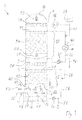
- Fig. 1 shows schematically a wet scrubber 1.
- the wet scrubber 1 is adapted for cleaning process gases, for example flue gases from a waste incineration plant, incinerating household and/or industrial waste, a coal- or oil-fired fired power plant, and/or a biofuel fired boiler.
- the wet scrubber 1 comprises a vertical wet scrubber tower 2, an inlet 4 arranged at a lower end 5 of the wet scrubber tower 2, for flue gases FG to be cleaned, and an outlet 6 arranged at an upper end 7 of the wet scrubber tower 2 for flue gases FG from which at least a portion of the content of gaseous pollutants have been removed.
- the wet scrubber 1 has a scrubbing stage 8 and a condensing stage 10 arranged in interior 3 of scrubbing tower 2.
- the scrubbing stage 8 and the condensing stage 10 are both arranged in the wet scrubbing tower 2, with the condensing stage 10 arranged vertically above the scrubbing stage 8.
- the scrubbing stage 8 comprises a tank 12.
- the tank 12 is arranged in the bottom 14 of the wet scrubber tower 2.
- a circulation pump 16 is, via a circulation pipe 18, fluidly connected to the tank 12.
- the circulation pump 16 is arranged to pump scrubbing liquid from the tank 12 to a fluidly connected liquid distributor 20 via the circulation pipe 18.
- the liquid distributor 20 is a liquid drip tube distributor.
- An advantage of such a liquid distributor 20 is that the liquid is supplied at a very low pressure to the liquid distributor 20, which means that the power consumed by the pump 16 is reduced. The liquid is then distributed in the liquid distributor and drips downwards.
- An example of a useful liquid distributor is the Splash-plate distributor VEP, which is available from Sulzer Chemtech AG, Winterthur, CH.
- the liquid distributor 20 distributes the liquid over a packing 22 of the scrubbing stage 8.
- the packing 22 is a structured packing arranged to provide efficient contact between the flue gas and the liquid.
- a structured packing is the Mellapak packing, which is available from Sulzer Chemtech AG, Winterthur, CH.
- the liquid may typically be water having a pH of about 0.2 to 3, more typically a pH of 0.5 to 2.
- a liquid of such pH is very efficient to capture, for example, hydrogen chloride, HCl, mercury, Hg, and ammonia, NH 3 , from the flue gas FG.
- liquid is drained from the scrubbing stage 8 via a drain pipe 24.
- the drained liquid containing captured HCl, Hg and NH 3 , may be forwarded to a water treatment plant (not shown) for being cleaned.
- Make up water which may, for example, be pure process water, or condensate from the condensing stage 10, is supplied to the scrubbing state 8 via a supply pipe 26.
- the at least partially cleaned flue gas FG moves vertically upwards from the scrubbing stage 8 and into the condensing stage 10.
- the condensing stage 10 comprises a liquid collector 28.
- the liquid collector 28 is arranged vertically above the scrubbing stage 8.
- the liquid collector 28 captures liquid coming from above, while allowing the flue gas FG to pass vertically upwards through the liquid collector 28.
- useful liquid collectors include the Vane collector SP, and the Chimney tray collector SK, both of which are available from Sulzer Chemtech AG, Winterthur, CH.
- a circulation pump 30 is, via a circulation pipe 32, fluidly connected to the liquid collector 28.
- the circulation pump 30 is arranged to pump condensing liquid from the liquid collector 28 to a fluidly connected liquid distributor 34 via the circulation pipe 32.
- the liquid distributor 34 is a liquid drip tube distributor to which the liquid is supplied at a very low pressure, which means that the power consumed by the pump 30 is reduced. The liquid is then distributed in the liquid distributor 34 and drips downwards.
- An example of a useful liquid distributor 34 is the Splash-plate distributor VEP, which is available from Sulzer Chemtech AG, Winterthur, CH.
- the liquid distributor 34 distributes the liquid over a packing 36 of the condensing stage 10.
- the packing 34 is a structured packing arranged to provide efficient contact between the flue gas and the liquid.
- a structured packing is the Mellapak packing, which is available from Sulzer Chemtech AG, Winterthur, CH.
- the liquid may typically be water having a pH of about 5 to 9, more typically a pH of 5.5 to 7.5.
- a liquid of such pH is very efficient to capture, for example, sulphur dioxide, SO 2 , from the flue gas FG.
- an alkaline substance may be added to the liquid. It is preferred that the liquid circulating in the condensing stage 10 is a clear liquid, and not a slurry.
- an alkaline substance is added from a source 38 to the liquid of the condensing stage 10 via a supply pipe 40 fluidly connected to the circulation pipe 32.
- a pH-meter 42 measuring the pH of the liquid circulating in the circulation pipe 32 controls the supply of alkaline substance from the source 40.
- the alkaline substance which is stored in the storage 38 and which is utilized for controlling the pH of the cooling liquid circulating in the condensing stage 10 has a solubility in water, at a temperature of 20°C, of at least 50 g/litre, more preferably at least 100 g/litre at 20°C.
- suitable alkaline substances include sodium hydroxide (NaOH), potassium hydroxide (KOH), sodium carbonate (Na 2 C0 3 ), and sodium bicarbonate (NaHCO 3 )
- the most preferred alkaline substance is sodium hydroxide (NaOH).
- a heat exchanger 44 is arranged for cooling the liquid circulating in the circulation pipe 32.
- the heat exchanger 44 may be connected to, for example, a boiler feed water heater, a district heating system, or some other system where there is a need for heat. Hence, the heat exchanger 44 cools the liquid circulating in the circulating pipe 32 and recovers heat for use in another system, where there is a need for the heat.
- the cooled liquid circulating in the pipe 32, downstream of the heat exchanger 44, is forwarded to the liquid distributor 34 and is brought into contact with the flue gas FG inside the packing 36 of the condensing stage 10.
- the flue gas FG will be cooled to a temperature which is lower than that temperature at which water vapor starts to condense from the flue gas FG.
- inside the packing 36 at least a portion of a water vapor content of the flue gas FG will condense and form liquid water.
- liquid water is continuously added to the liquid circulating in the condensing stage 10. To compensate for this liquid is drained from the condensing stage 10 via a drain pipe 46.
- the drained liquid, containing condensed water and captured SO 2 may be forwarded to a water treatment plant (not shown) for being cleaned.
- a water treatment plant not shown
- at least a portion of the liquid drained from the condensing stage 10 may be forwarded to the scrubbing stage 8 and supplied, via pipe 26, as make-up liquid.
- the at least partially cleaned flue gas FG moves vertically upwards from the condensing stage 10 and leaves the wet scrubber 1 via the outlet 6.
- An upper mist eliminator 48 may be arranged downstream of the condensing stage 10 to remove at least a portion of liquid droplets that are entrained with the flue gas FG to avoid that such liquid droplets leave the wet scrubber 1.
- An intermediate mist eliminator 50 may be arranged between the scrubbing stage 8 and the condensing stage 10 to remove at least a portion of liquid droplets that are entrained with the flue gas FG from the scrubbing stage 8 to avoid that such liquid droplets, having a low pH, enter the condensing stage 10.
- One example of a mist eliminator type that can be used as the upper and intermediate mist eliminators 48, 50 is the Sulzer Mellachevron mist eliminators, available from Sulzer Chemtech AG, Winterthur, CH.
- the inlet 4 comprises a horizontal inlet duct 52.
- the inlet duct is arranged for a horizontal flow of the flue gas FG entering the wet scrubber 1.
- the inlet duct 52 has an upper wall 54, and a lower wall 56.
- the lower wall 56 connects to the scrubbing tower 2 in a point 58 which is located above a liquid level LV of the liquid in the tank 12.
- the upper wall 54 connects to the scrubbing tower 2 in a point 60.
- the packing 22 of the scrubbing stage 8 has an underside 62.
- the point 60 is often located at a lower vertical level than the underside 62 of the packing 22.
- the vertical distance VD from the point 60 and up to the underside 62 is very short.
- the distance VD would be less than 50 cm, and more preferably less than 30 cm. It is also possible that the vertical distance VD is negative, i.e., that the underside 62 is located on a lower vertical level than the point 60. Such negative distance VD could be in the range of 0 to -10 cm, more prefarably in the range of 0 to -5 cm. Hence, the underside 62 could be located from 10 cm, preferably 5 cm, vertically below the point 60, and up to 50 cm, preferably 30 cm, vertically above the point 60. Most preferably, the distance VD is 0 to 10 cm, with the underside 62 located 0 to 10 cm vertically above the point 60.
- the combination of the horizontal inlet duct 52, the packing 22 and the short distance VD provides for efficient and even distribution of the flue gas FG within the horizontal cross-section of the interior 3 of the scrubbing tower 2.
- Liquid LC having passed through the packing 22 and leaving the packing 22 via the underside 62 thereof will be brought into contact with the flue gas FG entering via the inlet duct 52 and will cool the inlet flue gas FG just below the packing 22.
- the flue gas FG entering the inlet duct 52 may have a temperature of about 100°C.
- the temperature of the flue gas may be lowered to about 60°C.
- the flue gas FG is saturated with water vapor.
- the flue gas would have this temperature, 60°C, while passing through the scrubbing stage 8.
- the flue gas FG may be brought into contact with a liquid having a temperature, at the liquid distributor 34, of about 20°C.
- the flue gas FG is thereby, as an effect of being brought into contact with this cool liquid, gradually cooled from about 60°C to about 25°C while passing vertically upwards through the condensing stage 10.
- the liquid is heated from a temperature of approximately 20°C at the liquid distributor 34, to a temperature of about 55°C when collected at the liquid collector 28.
- heat is transferred from the flue gas FG to the liquid in the condensing stage 10.
- water vapor is condensed from the flue gas FG and forms liquid water as an effect of the cooling of the flue gas FG to a temperature that is below that temperature at which the flue gas FG is saturated with respect to water vapor.
- a wet scrubber for capturing gaseous pollutants and recovering heat from a process gas stream comprises a wet scrubber tower (2) having an inlet arranged at a lower end thereof, a scrubbing stage (8) arranged in the interior (3) of the wet scrubber tower (2) and comprising a structured packing (22) for bringing the process gas stream into contact with a scrubbing liquid for capturing at least one gaseous pollutant from the process gas stream, and a condensing stage (10) arranged inside the interior (3) of the wet scrubber tower vertically above the scrubbing stage (8) and comprising a structured packing (36) for bringing the process gas stream into contact with a condensing liquid for condensing at least a portion of a water vapor content of the process gas.
Landscapes
- Engineering & Computer Science (AREA)
- Chemical & Material Sciences (AREA)
- Environmental & Geological Engineering (AREA)
- Analytical Chemistry (AREA)
- General Chemical & Material Sciences (AREA)
- Oil, Petroleum & Natural Gas (AREA)
- Chemical Kinetics & Catalysis (AREA)
- Health & Medical Sciences (AREA)
- Biomedical Technology (AREA)
- Treating Waste Gases (AREA)
- Gas Separation By Absorption (AREA)
Abstract
a condensing stage (10) arranged inside the interior (3) of the wet scrubber tower vertically above the scrubbing stage (8) and comprising a structured packing (36) for bringing the process gas stream into contact with a condensing liquid for condensing at least a portion of a water vapor content of the process gas.
Description
- The present disclosure relates to a wet scrubber for removing gaseous pollutants from a process gas. The present disclosure also relates to a method of removing gaseous pollutants from a process gas.
- When separating gaseous pollutants from process gases, such as flue gases from, for example, a waste incineration plant, incinerating household and/or industrial waste, a coal- or oil-fired fired power plant, and/or a biofuel fired boiler, a method is frequently used, in which the flue gases are brought into contact with liquid in a wet scrubber to remove gaseous pollutants.
- An example of a wet scrubber is disclosed in
US 4,340,572 . The wet scrubber disclosed inUS 4,340,572 serves to both remove gaseous pollutants from the flue gas, and recovering heat from the flue gas. - The object of the present disclosure is to provide a method of cleaning a gas and recovering heat in a wet scrubber in a manner more efficient than that of the prior art.
- This object is achieved by a method for capturing gaseous pollutants and recovering heat from a process gas stream containing water vapor in a wet scrubber. The method comprises:
- transporting a process gas stream to an interior of a wet scrubber tower of the wet scrubber via an inlet arranged at a lower end thereof,
- bringing the process gas stream into contact with a scrubbing liquid in a structured packing of a scrubbing stage of the wet scrubber for capturing at least one gaseous pollutant from the process gas stream,
- transporting the process gas stream vertically upwards from the scrubbing stage to a condensing stage arranged vertically above the scrubbing stage, and
- bringing the process gas stream into contact with a condensing liquid in a structured packing of the condensing stage of the wet scrubber for condensing at least a portion of a water vapor content of the process gas.
- An advantage of this method is that cleaning and recovering heat is achieved in a very efficient manner with respect to investment and operating costs.
- A further object of the present disclosure is to provide a wet scrubber which is more efficient in cleaning a process gas, and which allows recovering heat of the flue gas.
- This object is achieved by means of a wet scrubber for capturing gaseous pollutants and recovering heat from a process gas stream containing water vapor, wherein the wet scrubber comprises:
- a wet scrubber tower having an inlet arranged at a lower end thereof, and an outlet arranged at an upper end thereof,
- a scrubbing stage arranged in the interior of the wet scrubber tower and comprising a structured packing for bringing the process gas stream entering the wet scrubber tower via the inlet into contact with a scrubbing liquid for capturing at least one gaseous pollutant from the process gas stream, and
- a condensing stage arranged inside the interior of the wet scrubber tower vertically above the scrubbing stage and comprising a structured packing for bringing the process gas stream into contact with a condensing liquid for condensing at least a portion of a water vapor content of the process gas.
- An advantage of this wet scrubber is that the investment cost becomes lower, compared to the scrubber of the prior art.
- According to one embodiment, the inlet further comprises a horizontal inlet duct. The horizontal duct requires a limited space.
- According to one embodiment the horizontal inlet duct has an upper wall, and a lower wall, wherein the upper wall connects to the wet scrubber tower in a point which is located a vertical distance (VD) of less than 50 cm below an underside of the packing of the scrubbing stage. An advantage of this embodiment is that the process gas stream is well distributed inside the wet scrubber tower using the structured packing which is also utilized for bringing the scrubbing liquid into contact with the flue gas. This reduces the need for any additional gas distribution devices, which reduces the investment cost and the height of the wet scrubber tower.
- According to one embodiment the vertical distance (VD) between the underside of the structured packing and said point is 0 to 30 cm.
- According to one embodiment at least one of the scrubbing stage and the condensing stage comprises a liquid drip tube distributor for distributing the scrubbing liquid over the respective structured packing. An advantage of this embodiment is that liquid may be supplied to the structured packing without requiring the high liquid pressures required in spray nozzle based distribution devices.
- Further objects and features of the present invention will be apparent from the description and the claims.
- The invention will now be described in more detail by way of exemplary embodiments and with reference to the accompanying drawings.
-
Fig. 1 is a schematic side view of a wet scrubber. -
Fig. 1 shows schematically a wet scrubber 1. The wet scrubber 1 is adapted for cleaning process gases, for example flue gases from a waste incineration plant, incinerating household and/or industrial waste, a coal- or oil-fired fired power plant, and/or a biofuel fired boiler. The wet scrubber 1 comprises a verticalwet scrubber tower 2, aninlet 4 arranged at a lower end 5 of thewet scrubber tower 2, for flue gases FG to be cleaned, and anoutlet 6 arranged at an upper end 7 of thewet scrubber tower 2 for flue gases FG from which at least a portion of the content of gaseous pollutants have been removed. - The wet scrubber 1 has a scrubbing stage 8 and a condensing
stage 10 arranged ininterior 3 ofscrubbing tower 2. The scrubbing stage 8 and thecondensing stage 10 are both arranged in thewet scrubbing tower 2, with the condensingstage 10 arranged vertically above the scrubbing stage 8. - The scrubbing stage 8 comprises a
tank 12. Thetank 12 is arranged in thebottom 14 of thewet scrubber tower 2. Acirculation pump 16 is, via acirculation pipe 18, fluidly connected to thetank 12. Thecirculation pump 16 is arranged to pump scrubbing liquid from thetank 12 to a fluidly connectedliquid distributor 20 via thecirculation pipe 18. According to one embodiment theliquid distributor 20 is a liquid drip tube distributor. An advantage of such aliquid distributor 20 is that the liquid is supplied at a very low pressure to theliquid distributor 20, which means that the power consumed by thepump 16 is reduced. The liquid is then distributed in the liquid distributor and drips downwards. An example of a useful liquid distributor is the Splash-plate distributor VEP, which is available from Sulzer Chemtech AG, Winterthur, CH. - The
liquid distributor 20 distributes the liquid over apacking 22 of the scrubbing stage 8. Thepacking 22 is a structured packing arranged to provide efficient contact between the flue gas and the liquid. One example of a structured packing is the Mellapak packing, which is available from Sulzer Chemtech AG, Winterthur, CH. - Inside the packing 22 the flue gas, FG forwarded vertically upward through the
packing 22 is brought into contact with the liquid. The liquid may typically be water having a pH of about 0.2 to 3, more typically a pH of 0.5 to 2. A liquid of such pH is very efficient to capture, for example, hydrogen chloride, HCl, mercury, Hg, and ammonia, NH3, from the flue gas FG. - To maintain the pH at a desired level in the scrubbing stage 8 liquid is drained from the scrubbing stage 8 via a
drain pipe 24. The drained liquid, containing captured HCl, Hg and NH3, may be forwarded to a water treatment plant (not shown) for being cleaned. Make up water, which may, for example, be pure process water, or condensate from thecondensing stage 10, is supplied to the scrubbing state 8 via asupply pipe 26. - The at least partially cleaned flue gas FG moves vertically upwards from the scrubbing stage 8 and into the condensing
stage 10. - The
condensing stage 10 comprises aliquid collector 28. Theliquid collector 28 is arranged vertically above the scrubbing stage 8. Theliquid collector 28 captures liquid coming from above, while allowing the flue gas FG to pass vertically upwards through theliquid collector 28. Examples of useful liquid collectors include the Vane collector SP, and the Chimney tray collector SK, both of which are available from Sulzer Chemtech AG, Winterthur, CH. - A
circulation pump 30 is, via acirculation pipe 32, fluidly connected to theliquid collector 28. Thecirculation pump 30 is arranged to pump condensing liquid from theliquid collector 28 to a fluidly connectedliquid distributor 34 via thecirculation pipe 32. According to one embodiment theliquid distributor 34 is a liquid drip tube distributor to which the liquid is supplied at a very low pressure, which means that the power consumed by thepump 30 is reduced. The liquid is then distributed in theliquid distributor 34 and drips downwards. An example of auseful liquid distributor 34 is the Splash-plate distributor VEP, which is available from Sulzer Chemtech AG, Winterthur, CH. - The
liquid distributor 34 distributes the liquid over a packing 36 of the condensingstage 10. The packing 34 is a structured packing arranged to provide efficient contact between the flue gas and the liquid. One example of a structured packing is the Mellapak packing, which is available from Sulzer Chemtech AG, Winterthur, CH. - Inside the packing 36 the flue gas, FG forwarded vertically upward through the packing 36 is brought into contact with the liquid supplied by the
pump 30. The liquid may typically be water having a pH of about 5 to 9, more typically a pH of 5.5 to 7.5. A liquid of such pH is very efficient to capture, for example, sulphur dioxide, SO2, from the flue gas FG. - To maintain the pH at a desired level in the condensing
stage 10 an alkaline substance may be added to the liquid. It is preferred that the liquid circulating in the condensingstage 10 is a clear liquid, and not a slurry. In one embodiment an alkaline substance is added from asource 38 to the liquid of the condensingstage 10 via asupply pipe 40 fluidly connected to thecirculation pipe 32. A pH-meter 42 measuring the pH of the liquid circulating in thecirculation pipe 32 controls the supply of alkaline substance from thesource 40. Preferably, the alkaline substance which is stored in thestorage 38 and which is utilized for controlling the pH of the cooling liquid circulating in the condensingstage 10 has a solubility in water, at a temperature of 20°C, of at least 50 g/litre, more preferably at least 100 g/litre at 20°C. Examples of suitable alkaline substances include sodium hydroxide (NaOH), potassium hydroxide (KOH), sodium carbonate (Na2C03), and sodium bicarbonate (NaHCO3) Often, the most preferred alkaline substance is sodium hydroxide (NaOH). - A
heat exchanger 44 is arranged for cooling the liquid circulating in thecirculation pipe 32. Theheat exchanger 44 may be connected to, for example, a boiler feed water heater, a district heating system, or some other system where there is a need for heat. Hence, theheat exchanger 44 cools the liquid circulating in the circulatingpipe 32 and recovers heat for use in another system, where there is a need for the heat. - The cooled liquid circulating in the
pipe 32, downstream of theheat exchanger 44, is forwarded to theliquid distributor 34 and is brought into contact with the flue gas FG inside the packing 36 of the condensingstage 10. As an effect of such contact the flue gas FG will be cooled to a temperature which is lower than that temperature at which water vapor starts to condense from the flue gas FG. Hence, inside the packing 36 at least a portion of a water vapor content of the flue gas FG will condense and form liquid water. This means that liquid water is continuously added to the liquid circulating in the condensingstage 10. To compensate for this liquid is drained from the condensingstage 10 via adrain pipe 46. The drained liquid, containing condensed water and captured SO2, may be forwarded to a water treatment plant (not shown) for being cleaned. Optionally at least a portion of the liquid drained from the condensingstage 10 may be forwarded to the scrubbing stage 8 and supplied, viapipe 26, as make-up liquid. - The at least partially cleaned flue gas FG moves vertically upwards from the condensing
stage 10 and leaves the wet scrubber 1 via theoutlet 6. - An
upper mist eliminator 48 may be arranged downstream of the condensingstage 10 to remove at least a portion of liquid droplets that are entrained with the flue gas FG to avoid that such liquid droplets leave the wet scrubber 1. Anintermediate mist eliminator 50 may be arranged between the scrubbing stage 8 and the condensingstage 10 to remove at least a portion of liquid droplets that are entrained with the flue gas FG from the scrubbing stage 8 to avoid that such liquid droplets, having a low pH, enter the condensingstage 10. One example of a mist eliminator type that can be used as the upper andintermediate mist eliminators - The
inlet 4 comprises ahorizontal inlet duct 52. The inlet duct is arranged for a horizontal flow of the flue gas FG entering the wet scrubber 1. Theinlet duct 52 has anupper wall 54, and a lower wall 56. The lower wall 56 connects to the scrubbingtower 2 in a point 58 which is located above a liquid level LV of the liquid in thetank 12. Theupper wall 54 connects to the scrubbingtower 2 in apoint 60. The packing 22 of the scrubbing stage 8 has anunderside 62. Thepoint 60 is often located at a lower vertical level than theunderside 62 of the packing 22. The vertical distance VD from thepoint 60 and up to theunderside 62 is very short. Typically the distance VD would be less than 50 cm, and more preferably less than 30 cm. It is also possible that the vertical distance VD is negative, i.e., that theunderside 62 is located on a lower vertical level than thepoint 60. Such negative distance VD could be in the range of 0 to -10 cm, more prefarably in the range of 0 to -5 cm. Hence, theunderside 62 could be located from 10 cm, preferably 5 cm, vertically below thepoint 60, and up to 50 cm, preferably 30 cm, vertically above thepoint 60. Most preferably, the distance VD is 0 to 10 cm, with theunderside 62 located 0 to 10 cm vertically above thepoint 60. The combination of thehorizontal inlet duct 52, the packing 22 and the short distance VD provides for efficient and even distribution of the flue gas FG within the horizontal cross-section of theinterior 3 of the scrubbingtower 2. Liquid LC having passed through the packing 22 and leaving the packing 22 via theunderside 62 thereof will be brought into contact with the flue gas FG entering via theinlet duct 52 and will cool the inlet flue gas FG just below the packing 22. - In accordance with one example, the flue gas FG entering the
inlet duct 52 may have a temperature of about 100°C. Upon being brought into contact with the liquid LC, the temperature of the flue gas may be lowered to about 60°C. At this temperature the flue gas FG is saturated with water vapor. The flue gas would have this temperature, 60°C, while passing through the scrubbing stage 8. In the condensingstage 10 the flue gas FG may be brought into contact with a liquid having a temperature, at theliquid distributor 34, of about 20°C. The flue gas FG is thereby, as an effect of being brought into contact with this cool liquid, gradually cooled from about 60°C to about 25°C while passing vertically upwards through the condensingstage 10. At the same time the liquid is heated from a temperature of approximately 20°C at theliquid distributor 34, to a temperature of about 55°C when collected at theliquid collector 28. Hence, heat is transferred from the flue gas FG to the liquid in the condensingstage 10. Furthermore, water vapor is condensed from the flue gas FG and forms liquid water as an effect of the cooling of the flue gas FG to a temperature that is below that temperature at which the flue gas FG is saturated with respect to water vapor. - It will be appreciated that numerous variants of the embodiments described above are possible within the scope of the appended claims.
- To summarize, a wet scrubber for capturing gaseous pollutants and recovering heat from a process gas stream comprises
a wet scrubber tower (2) having an inlet arranged at a lower end thereof,
a scrubbing stage (8) arranged in the interior (3) of the wet scrubber tower (2) and comprising a structured packing (22) for bringing the process gas stream into contact with a scrubbing liquid for capturing at least one gaseous pollutant from the process gas stream, and
a condensing stage (10) arranged inside the interior (3) of the wet scrubber tower vertically above the scrubbing stage (8) and comprising a structured packing (36) for bringing the process gas stream into contact with a condensing liquid for condensing at least a portion of a water vapor content of the process gas. - While the invention has been described with reference to a number of preferred embodiments, it will be understood by those skilled in the art that various changes may be made and equivalents may be substituted for elements thereof without departing from the scope of the present invention. In addition, many modifications may be made to adapt a particular situation or material to the teachings of the invention without departing from the essential scope thereof. Therefore, it is intended that the invention not be limited to the particular embodiments disclosed as the best mode contemplated for carrying out this invention, but that the invention will include all embodiments falling within the scope of the appended claims. Moreover, the use of the terms first, second, etc. do not denote any order or importance, but rather the terms first, second, etc. are used to distinguish one element from another.
Claims (12)
- A method for capturing gaseous pollutants and recovering heat from a process gas stream containing water vapor in a wet scrubber, characterised in
transporting a process gas stream to an interior of a wet scrubber tower of the wet scrubber via an inlet arranged at a lower end thereof,
bringing the process gas stream into contact with a scrubbing liquid in a structured packing of a scrubbing stage of the wet scrubber for capturing at least one gaseous pollutant from the process gas stream,
transporting the process gas stream vertically upwards from the scrubbing stage to a condensing stage arranged vertically above the scrubbing stage, and
bringing the process gas stream into contact with a condensing liquid in a structured packing of the condensing stage of the wet scrubber for condensing at least a portion of a water vapor content of the process gas. - A method according to claim 1, further comprising forwarding the process gas stream into the wet scrubber tower in a horizontal gas flow direction.
- A method according to claim 2, further comprising forwarding the process gas stream into the wet scrubber tower via a horizontal inlet duct having an upper wall, and a lower wall, wherein the upper wall connects to the wet scrubber tower in a point which is located a vertical distance (VD) of less than 50 cm below an underside of the structured packing of the scrubbing stage.
- A method according to any one of the preceding claims, wherein the scrubbing liquid of the scrubbing stage has a pH of 0.2 to 3, and wherein the condensing liquid of the condensing stage has a pH of 5 to 9.
- A wet scrubber for capturing gaseous pollutants and recovering heat from a process gas stream containing water vapor, characterised in the wet scrubber comprising:a wet scrubber tower having an inlet arranged at a lower end thereof, and an outlet arranged at an upper end thereof,a scrubbing stage arranged in the interior of the wet scrubber tower and comprising a structured packing for bringing the process gas stream entering the wet scrubber tower via the inlet into contact with a scrubbing liquid for capturing at least one gaseous pollutant from the process gas stream, anda condensing stage arranged inside the interior of the wet scrubber tower vertically above the scrubbing stage and comprising a structured packing for bringing the process gas stream into contact with a condensing liquid for condensing at least a portion of a water vapor content of the process gas.
- A wet scrubber according to claim 5, the inlet further comprising a horizontal inlet duct.
- A wet scrubber according to claim 6, wherein the horizontal inlet duct has an upper wall, and a lower wall, wherein the upper wall connects to the wet scrubber tower in a point which is located a vertical distance (VD) of less than 50 cm below an underside of the structured packing of the scrubbing stage.
- A wet scrubber according to claim 7, wherein the vertical distance (VD) is 0 to 30 cm.
- A wet scrubber according to any one of claims 5-8, wherein at least one of the scrubbing stage and the condensing stage comprises a liquid drip tube distributor for distributing the scrubbing liquid over the respective structured packing.
- A wet scrubber according to any one of claims 5-9, wherein a liquid collector is arranged between the structured packing of the scrubbing stage and the structured packing of the condensing stage for collecting condensing liquid that has passed through the condensing stage.
- A wet scrubber according to any one of claims 5-10, wherein the wet scrubber comprises a source for supply of an alkaline substance to the condensing stage.
- A wet scrubber according to any one of claims 5-11, wherein an intermediate mist eliminator is arranged between the scrubbing stage and the condensing stage.
Priority Applications (2)
| Application Number | Priority Date | Filing Date | Title |
|---|---|---|---|
| EP12162726.9A EP2644254B1 (en) | 2012-03-30 | 2012-03-30 | Scrubber for cleaning a process gas and recovering heat |
| PL12162726T PL2644254T3 (en) | 2012-03-30 | 2012-03-30 | Scrubber for cleaning a process gas and recovering heat |
Applications Claiming Priority (1)
| Application Number | Priority Date | Filing Date | Title |
|---|---|---|---|
| EP12162726.9A EP2644254B1 (en) | 2012-03-30 | 2012-03-30 | Scrubber for cleaning a process gas and recovering heat |
Publications (2)
| Publication Number | Publication Date |
|---|---|
| EP2644254A1 true EP2644254A1 (en) | 2013-10-02 |
| EP2644254B1 EP2644254B1 (en) | 2016-08-17 |
Family
ID=46027583
Family Applications (1)
| Application Number | Title | Priority Date | Filing Date |
|---|---|---|---|
| EP12162726.9A Active EP2644254B1 (en) | 2012-03-30 | 2012-03-30 | Scrubber for cleaning a process gas and recovering heat |
Country Status (2)
| Country | Link |
|---|---|
| EP (1) | EP2644254B1 (en) |
| PL (1) | PL2644254T3 (en) |
Cited By (4)
| Publication number | Priority date | Publication date | Assignee | Title |
|---|---|---|---|---|
| CN105013309A (en) * | 2015-07-01 | 2015-11-04 | 太仓市顺邦防腐设备有限公司 | Multifunctional waste gas purification tower |
| CN107321127A (en) * | 2017-07-06 | 2017-11-07 | 大唐东北电力试验研究所有限公司 | Ammoniacal liquor recovery system and method in thermal power plant's condenser |
| CN107569980A (en) * | 2017-09-30 | 2018-01-12 | 江苏迈克化工机械有限公司 | A kind of multistage composite Ammonic washing tower |
| FI131513B1 (en) * | 2022-08-25 | 2025-05-30 | Aliceco Ip Oy | System and method for efficient district heating |
Citations (4)
| Publication number | Priority date | Publication date | Assignee | Title |
|---|---|---|---|---|
| US3638708A (en) * | 1969-06-11 | 1972-02-01 | Marathon Engineering Inc | Methods of multiple stage evaporation from heat sources other than steam |
| US3733777A (en) * | 1971-06-10 | 1973-05-22 | R Huntington | Flue gas recovery method and apparatus |
| US3957951A (en) * | 1974-08-23 | 1976-05-18 | International Telephone And Telegraph Corporation | Process for removing contaminants from hot waste gas streams |
| US4340572A (en) | 1978-05-19 | 1982-07-20 | Woodside Construction, Inc. | Process for recovering heat from stack or flue gas |
Family Cites Families (5)
| Publication number | Priority date | Publication date | Assignee | Title |
|---|---|---|---|---|
| ATE425806T1 (en) * | 1998-11-23 | 2009-04-15 | Fluor Corp | DEVICE FOR DIVIDING A FLOW |
| JP3969949B2 (en) * | 2000-10-25 | 2007-09-05 | 関西電力株式会社 | Amine recovery method and apparatus, and decarbonation gas apparatus provided with the same |
| AU2009216164B2 (en) * | 2008-02-22 | 2011-10-13 | Mitsubishi Heavy Industries, Ltd. | Apparatus for recovering CO2 and method of recovering CO2 |
| NO332812B1 (en) * | 2009-03-13 | 2013-01-21 | Aker Clean Carbon As | Amine emission control |
| JP5638262B2 (en) * | 2010-02-23 | 2014-12-10 | 三菱重工業株式会社 | CO2 recovery apparatus and CO2 recovery method |
-
2012
- 2012-03-30 EP EP12162726.9A patent/EP2644254B1/en active Active
- 2012-03-30 PL PL12162726T patent/PL2644254T3/en unknown
Patent Citations (4)
| Publication number | Priority date | Publication date | Assignee | Title |
|---|---|---|---|---|
| US3638708A (en) * | 1969-06-11 | 1972-02-01 | Marathon Engineering Inc | Methods of multiple stage evaporation from heat sources other than steam |
| US3733777A (en) * | 1971-06-10 | 1973-05-22 | R Huntington | Flue gas recovery method and apparatus |
| US3957951A (en) * | 1974-08-23 | 1976-05-18 | International Telephone And Telegraph Corporation | Process for removing contaminants from hot waste gas streams |
| US4340572A (en) | 1978-05-19 | 1982-07-20 | Woodside Construction, Inc. | Process for recovering heat from stack or flue gas |
Cited By (4)
| Publication number | Priority date | Publication date | Assignee | Title |
|---|---|---|---|---|
| CN105013309A (en) * | 2015-07-01 | 2015-11-04 | 太仓市顺邦防腐设备有限公司 | Multifunctional waste gas purification tower |
| CN107321127A (en) * | 2017-07-06 | 2017-11-07 | 大唐东北电力试验研究所有限公司 | Ammoniacal liquor recovery system and method in thermal power plant's condenser |
| CN107569980A (en) * | 2017-09-30 | 2018-01-12 | 江苏迈克化工机械有限公司 | A kind of multistage composite Ammonic washing tower |
| FI131513B1 (en) * | 2022-08-25 | 2025-05-30 | Aliceco Ip Oy | System and method for efficient district heating |
Also Published As
| Publication number | Publication date |
|---|---|
| EP2644254B1 (en) | 2016-08-17 |
| PL2644254T3 (en) | 2017-03-31 |
Similar Documents
| Publication | Publication Date | Title |
|---|---|---|
| AU2010325773B2 (en) | A method and device for cleaning a carbon dioxide rich flue gas | |
| US9901872B2 (en) | Air pollution control system | |
| AU2008316968B2 (en) | Multi-stage CO2 removal system and method for processing a flue gas stream | |
| AU2012212630B2 (en) | Gas treatment process and system | |
| EP2898940B1 (en) | Carbon dioxide recovery device | |
| EP2703063A1 (en) | Desulphurization and cooling of process gas | |
| US20130098104A1 (en) | Method and system for condensing water vapour from a carbon dioxide rich flue gas | |
| US8387545B2 (en) | Water recovery from flue gas in steam-assisted production | |
| US20150101485A1 (en) | Method and apparatus for wet desulfurization spray towers | |
| EP2510998B1 (en) | Compression condensate conditioning in the flue gas condenser | |
| JP2013202422A (en) | Method and apparatus for treating combustion exhaust gas of coal fired boiler | |
| US9492786B2 (en) | Multi-purpose absorber | |
| KR20160062707A (en) | System and method for reducing gas emissions from wet flue gas desulfurization waste water | |
| EP2644254B1 (en) | Scrubber for cleaning a process gas and recovering heat | |
| JP6173734B2 (en) | Exhaust gas treatment system | |
| CN109078445A (en) | Flue gas ash removal takes off white integrated apparatus | |
| CN101332410A (en) | Exhaust gas treatment device and exhaust gas treatment method | |
| CA2710687C (en) | Water recovery from flue gas in steam-assisted production |
Legal Events
| Date | Code | Title | Description |
|---|---|---|---|
| PUAI | Public reference made under article 153(3) epc to a published international application that has entered the european phase |
Free format text: ORIGINAL CODE: 0009012 |
|
| AK | Designated contracting states |
Kind code of ref document: A1 Designated state(s): AL AT BE BG CH CY CZ DE DK EE ES FI FR GB GR HR HU IE IS IT LI LT LU LV MC MK MT NL NO PL PT RO RS SE SI SK SM TR |
|
| AX | Request for extension of the european patent |
Extension state: BA ME |
|
| 17P | Request for examination filed |
Effective date: 20131220 |
|
| RBV | Designated contracting states (corrected) |
Designated state(s): AL AT BE BG CH CY CZ DE DK EE ES FI FR GB GR HR HU IE IS IT LI LT LU LV MC MK MT NL NO PL PT RO RS SE SI SK SM TR |
|
| 17Q | First examination report despatched |
Effective date: 20140526 |
|
| REG | Reference to a national code |
Ref country code: DE Ref legal event code: R079 Ref document number: 602012021741 Country of ref document: DE Free format text: PREVIOUS MAIN CLASS: B01D0053340000 Ipc: B01D0053140000 |
|
| GRAP | Despatch of communication of intention to grant a patent |
Free format text: ORIGINAL CODE: EPIDOSNIGR1 |
|
| RIC1 | Information provided on ipc code assigned before grant |
Ipc: B01D 53/14 20060101AFI20160216BHEP |
|
| INTG | Intention to grant announced |
Effective date: 20160311 |
|
| GRAS | Grant fee paid |
Free format text: ORIGINAL CODE: EPIDOSNIGR3 |
|
| GRAA | (expected) grant |
Free format text: ORIGINAL CODE: 0009210 |
|
| AK | Designated contracting states |
Kind code of ref document: B1 Designated state(s): AL AT BE BG CH CY CZ DE DK EE ES FI FR GB GR HR HU IE IS IT LI LT LU LV MC MK MT NL NO PL PT RO RS SE SI SK SM TR |
|
| RAP1 | Party data changed (applicant data changed or rights of an application transferred) |
Owner name: GENERAL ELECTRIC TECHNOLOGY GMBH |
|
| REG | Reference to a national code |
Ref country code: GB Ref legal event code: FG4D |
|
| REG | Reference to a national code |
Ref country code: CH Ref legal event code: EP |
|
| REG | Reference to a national code |
Ref country code: IE Ref legal event code: FG4D |
|
| REG | Reference to a national code |
Ref country code: AT Ref legal event code: REF Ref document number: 820512 Country of ref document: AT Kind code of ref document: T Effective date: 20160915 |
|
| REG | Reference to a national code |
Ref country code: DE Ref legal event code: R096 Ref document number: 602012021741 Country of ref document: DE |
|
| REG | Reference to a national code |
Ref country code: SE Ref legal event code: TRGR |
|
| REG | Reference to a national code |
Ref country code: NL Ref legal event code: MP Effective date: 20160817 |
|
| REG | Reference to a national code |
Ref country code: LT Ref legal event code: MG4D |
|
| PG25 | Lapsed in a contracting state [announced via postgrant information from national office to epo] |
Ref country code: RS Free format text: LAPSE BECAUSE OF FAILURE TO SUBMIT A TRANSLATION OF THE DESCRIPTION OR TO PAY THE FEE WITHIN THE PRESCRIBED TIME-LIMIT Effective date: 20160817 Ref country code: LT Free format text: LAPSE BECAUSE OF FAILURE TO SUBMIT A TRANSLATION OF THE DESCRIPTION OR TO PAY THE FEE WITHIN THE PRESCRIBED TIME-LIMIT Effective date: 20160817 Ref country code: NO Free format text: LAPSE BECAUSE OF FAILURE TO SUBMIT A TRANSLATION OF THE DESCRIPTION OR TO PAY THE FEE WITHIN THE PRESCRIBED TIME-LIMIT Effective date: 20161117 Ref country code: FI Free format text: LAPSE BECAUSE OF FAILURE TO SUBMIT A TRANSLATION OF THE DESCRIPTION OR TO PAY THE FEE WITHIN THE PRESCRIBED TIME-LIMIT Effective date: 20160817 Ref country code: NL Free format text: LAPSE BECAUSE OF FAILURE TO SUBMIT A TRANSLATION OF THE DESCRIPTION OR TO PAY THE FEE WITHIN THE PRESCRIBED TIME-LIMIT Effective date: 20160817 Ref country code: HR Free format text: LAPSE BECAUSE OF FAILURE TO SUBMIT A TRANSLATION OF THE DESCRIPTION OR TO PAY THE FEE WITHIN THE PRESCRIBED TIME-LIMIT Effective date: 20160817 |
|
| PG25 | Lapsed in a contracting state [announced via postgrant information from national office to epo] |
Ref country code: LV Free format text: LAPSE BECAUSE OF FAILURE TO SUBMIT A TRANSLATION OF THE DESCRIPTION OR TO PAY THE FEE WITHIN THE PRESCRIBED TIME-LIMIT Effective date: 20160817 Ref country code: PT Free format text: LAPSE BECAUSE OF FAILURE TO SUBMIT A TRANSLATION OF THE DESCRIPTION OR TO PAY THE FEE WITHIN THE PRESCRIBED TIME-LIMIT Effective date: 20161219 Ref country code: ES Free format text: LAPSE BECAUSE OF FAILURE TO SUBMIT A TRANSLATION OF THE DESCRIPTION OR TO PAY THE FEE WITHIN THE PRESCRIBED TIME-LIMIT Effective date: 20160817 Ref country code: GR Free format text: LAPSE BECAUSE OF FAILURE TO SUBMIT A TRANSLATION OF THE DESCRIPTION OR TO PAY THE FEE WITHIN THE PRESCRIBED TIME-LIMIT Effective date: 20161118 |
|
| REG | Reference to a national code |
Ref country code: FR Ref legal event code: PLFP Year of fee payment: 6 |
|
| PG25 | Lapsed in a contracting state [announced via postgrant information from national office to epo] |
Ref country code: RO Free format text: LAPSE BECAUSE OF FAILURE TO SUBMIT A TRANSLATION OF THE DESCRIPTION OR TO PAY THE FEE WITHIN THE PRESCRIBED TIME-LIMIT Effective date: 20160817 Ref country code: EE Free format text: LAPSE BECAUSE OF FAILURE TO SUBMIT A TRANSLATION OF THE DESCRIPTION OR TO PAY THE FEE WITHIN THE PRESCRIBED TIME-LIMIT Effective date: 20160817 |
|
| REG | Reference to a national code |
Ref country code: DE Ref legal event code: R097 Ref document number: 602012021741 Country of ref document: DE |
|
| PG25 | Lapsed in a contracting state [announced via postgrant information from national office to epo] |
Ref country code: SM Free format text: LAPSE BECAUSE OF FAILURE TO SUBMIT A TRANSLATION OF THE DESCRIPTION OR TO PAY THE FEE WITHIN THE PRESCRIBED TIME-LIMIT Effective date: 20160817 Ref country code: CZ Free format text: LAPSE BECAUSE OF FAILURE TO SUBMIT A TRANSLATION OF THE DESCRIPTION OR TO PAY THE FEE WITHIN THE PRESCRIBED TIME-LIMIT Effective date: 20160817 Ref country code: BE Free format text: LAPSE BECAUSE OF FAILURE TO SUBMIT A TRANSLATION OF THE DESCRIPTION OR TO PAY THE FEE WITHIN THE PRESCRIBED TIME-LIMIT Effective date: 20160817 Ref country code: BG Free format text: LAPSE BECAUSE OF FAILURE TO SUBMIT A TRANSLATION OF THE DESCRIPTION OR TO PAY THE FEE WITHIN THE PRESCRIBED TIME-LIMIT Effective date: 20161117 Ref country code: DK Free format text: LAPSE BECAUSE OF FAILURE TO SUBMIT A TRANSLATION OF THE DESCRIPTION OR TO PAY THE FEE WITHIN THE PRESCRIBED TIME-LIMIT Effective date: 20160817 Ref country code: SK Free format text: LAPSE BECAUSE OF FAILURE TO SUBMIT A TRANSLATION OF THE DESCRIPTION OR TO PAY THE FEE WITHIN THE PRESCRIBED TIME-LIMIT Effective date: 20160817 |
|
| PLBE | No opposition filed within time limit |
Free format text: ORIGINAL CODE: 0009261 |
|
| STAA | Information on the status of an ep patent application or granted ep patent |
Free format text: STATUS: NO OPPOSITION FILED WITHIN TIME LIMIT |
|
| 26N | No opposition filed |
Effective date: 20170518 |
|
| PG25 | Lapsed in a contracting state [announced via postgrant information from national office to epo] |
Ref country code: SI Free format text: LAPSE BECAUSE OF FAILURE TO SUBMIT A TRANSLATION OF THE DESCRIPTION OR TO PAY THE FEE WITHIN THE PRESCRIBED TIME-LIMIT Effective date: 20160817 |
|
| PG25 | Lapsed in a contracting state [announced via postgrant information from national office to epo] |
Ref country code: MC Free format text: LAPSE BECAUSE OF FAILURE TO SUBMIT A TRANSLATION OF THE DESCRIPTION OR TO PAY THE FEE WITHIN THE PRESCRIBED TIME-LIMIT Effective date: 20160817 |
|
| REG | Reference to a national code |
Ref country code: IE Ref legal event code: MM4A |
|
| PG25 | Lapsed in a contracting state [announced via postgrant information from national office to epo] |
Ref country code: LU Free format text: LAPSE BECAUSE OF NON-PAYMENT OF DUE FEES Effective date: 20170330 |
|
| PG25 | Lapsed in a contracting state [announced via postgrant information from national office to epo] |
Ref country code: IE Free format text: LAPSE BECAUSE OF NON-PAYMENT OF DUE FEES Effective date: 20170330 |
|
| REG | Reference to a national code |
Ref country code: FR Ref legal event code: PLFP Year of fee payment: 7 |
|
| PG25 | Lapsed in a contracting state [announced via postgrant information from national office to epo] |
Ref country code: MT Free format text: LAPSE BECAUSE OF NON-PAYMENT OF DUE FEES Effective date: 20170330 |
|
| PG25 | Lapsed in a contracting state [announced via postgrant information from national office to epo] |
Ref country code: AL Free format text: LAPSE BECAUSE OF FAILURE TO SUBMIT A TRANSLATION OF THE DESCRIPTION OR TO PAY THE FEE WITHIN THE PRESCRIBED TIME-LIMIT Effective date: 20160817 |
|
| PG25 | Lapsed in a contracting state [announced via postgrant information from national office to epo] |
Ref country code: HU Free format text: LAPSE BECAUSE OF FAILURE TO SUBMIT A TRANSLATION OF THE DESCRIPTION OR TO PAY THE FEE WITHIN THE PRESCRIBED TIME-LIMIT; INVALID AB INITIO Effective date: 20120330 |
|
| REG | Reference to a national code |
Ref country code: AT Ref legal event code: UEP Ref document number: 820512 Country of ref document: AT Kind code of ref document: T Effective date: 20160817 |
|
| PG25 | Lapsed in a contracting state [announced via postgrant information from national office to epo] |
Ref country code: CY Free format text: LAPSE BECAUSE OF NON-PAYMENT OF DUE FEES Effective date: 20160817 |
|
| PG25 | Lapsed in a contracting state [announced via postgrant information from national office to epo] |
Ref country code: MK Free format text: LAPSE BECAUSE OF FAILURE TO SUBMIT A TRANSLATION OF THE DESCRIPTION OR TO PAY THE FEE WITHIN THE PRESCRIBED TIME-LIMIT Effective date: 20160817 |
|
| PG25 | Lapsed in a contracting state [announced via postgrant information from national office to epo] |
Ref country code: TR Free format text: LAPSE BECAUSE OF FAILURE TO SUBMIT A TRANSLATION OF THE DESCRIPTION OR TO PAY THE FEE WITHIN THE PRESCRIBED TIME-LIMIT Effective date: 20160817 |
|
| PGFP | Annual fee paid to national office [announced via postgrant information from national office to epo] |
Ref country code: AT Payment date: 20200227 Year of fee payment: 9 Ref country code: GB Payment date: 20200221 Year of fee payment: 9 |
|
| PG25 | Lapsed in a contracting state [announced via postgrant information from national office to epo] |
Ref country code: IS Free format text: LAPSE BECAUSE OF FAILURE TO SUBMIT A TRANSLATION OF THE DESCRIPTION OR TO PAY THE FEE WITHIN THE PRESCRIBED TIME-LIMIT Effective date: 20161217 |
|
| REG | Reference to a national code |
Ref country code: AT Ref legal event code: MM01 Ref document number: 820512 Country of ref document: AT Kind code of ref document: T Effective date: 20210330 |
|
| GBPC | Gb: european patent ceased through non-payment of renewal fee |
Effective date: 20210330 |
|
| PG25 | Lapsed in a contracting state [announced via postgrant information from national office to epo] |
Ref country code: AT Free format text: LAPSE BECAUSE OF NON-PAYMENT OF DUE FEES Effective date: 20210330 Ref country code: GB Free format text: LAPSE BECAUSE OF NON-PAYMENT OF DUE FEES Effective date: 20210330 |
|
| PGFP | Annual fee paid to national office [announced via postgrant information from national office to epo] |
Ref country code: IT Payment date: 20220322 Year of fee payment: 11 |
|
| REG | Reference to a national code |
Ref country code: DE Ref legal event code: R081 Ref document number: 602012021741 Country of ref document: DE Owner name: ANDRITZ AKTIEBOLAG, SE Free format text: FORMER OWNER: GENERAL ELECTRIC TECHNOLOGY GMBH, BADEN, CH |
|
| P01 | Opt-out of the competence of the unified patent court (upc) registered |
Effective date: 20230523 |
|
| PG25 | Lapsed in a contracting state [announced via postgrant information from national office to epo] |
Ref country code: IT Free format text: LAPSE BECAUSE OF NON-PAYMENT OF DUE FEES Effective date: 20230330 |
|
| REG | Reference to a national code |
Ref country code: DE Ref legal event code: R082 Ref document number: 602012021741 Country of ref document: DE Representative=s name: DENNEMEYER & ASSOCIATES RECHTSANWALTSGESELLSCH, DE |
|
| PGFP | Annual fee paid to national office [announced via postgrant information from national office to epo] |
Ref country code: CH Payment date: 20250401 Year of fee payment: 14 |
|
| REG | Reference to a national code |
Ref country code: CH Ref legal event code: U11 Free format text: ST27 STATUS EVENT CODE: U-0-0-U10-U11 (AS PROVIDED BY THE NATIONAL OFFICE) Effective date: 20260401 |
|
| PGFP | Annual fee paid to national office [announced via postgrant information from national office to epo] |
Ref country code: SE Payment date: 20260319 Year of fee payment: 15 |
|
| PGFP | Annual fee paid to national office [announced via postgrant information from national office to epo] |
Ref country code: DE Payment date: 20260319 Year of fee payment: 15 |
|
| PGFP | Annual fee paid to national office [announced via postgrant information from national office to epo] |
Ref country code: FR Payment date: 20260320 Year of fee payment: 15 |
|
| PGFP | Annual fee paid to national office [announced via postgrant information from national office to epo] |
Ref country code: PL Payment date: 20260319 Year of fee payment: 15 |