EP2644214A2 - Medical dressings, systems, and methods employing sealants - Google Patents
Medical dressings, systems, and methods employing sealants Download PDFInfo
- Publication number
- EP2644214A2 EP2644214A2 EP13173894.0A EP13173894A EP2644214A2 EP 2644214 A2 EP2644214 A2 EP 2644214A2 EP 13173894 A EP13173894 A EP 13173894A EP 2644214 A2 EP2644214 A2 EP 2644214A2
- Authority
- EP
- European Patent Office
- Prior art keywords
- seal
- tissue site
- drape
- sealant
- reduced pressure
- Prior art date
- Legal status (The legal status is an assumption and is not a legal conclusion. Google has not performed a legal analysis and makes no representation as to the accuracy of the status listed.)
- Granted
Links
Images
Classifications
-
- A—HUMAN NECESSITIES
- A61—MEDICAL OR VETERINARY SCIENCE; HYGIENE
- A61F—FILTERS IMPLANTABLE INTO BLOOD VESSELS; PROSTHESES; DEVICES PROVIDING PATENCY TO, OR PREVENTING COLLAPSING OF, TUBULAR STRUCTURES OF THE BODY, e.g. STENTS; ORTHOPAEDIC, NURSING OR CONTRACEPTIVE DEVICES; FOMENTATION; TREATMENT OR PROTECTION OF EYES OR EARS; BANDAGES, DRESSINGS OR ABSORBENT PADS; FIRST-AID KITS
- A61F13/00—Bandages or dressings; Absorbent pads
- A61F13/05—Bandages or dressings; Absorbent pads specially adapted for use with sub-pressure or over-pressure therapy, wound drainage or wound irrigation, e.g. for use with negative-pressure wound therapy [NPWT]
-
- A—HUMAN NECESSITIES
- A61—MEDICAL OR VETERINARY SCIENCE; HYGIENE
- A61F—FILTERS IMPLANTABLE INTO BLOOD VESSELS; PROSTHESES; DEVICES PROVIDING PATENCY TO, OR PREVENTING COLLAPSING OF, TUBULAR STRUCTURES OF THE BODY, e.g. STENTS; ORTHOPAEDIC, NURSING OR CONTRACEPTIVE DEVICES; FOMENTATION; TREATMENT OR PROTECTION OF EYES OR EARS; BANDAGES, DRESSINGS OR ABSORBENT PADS; FIRST-AID KITS
- A61F13/00—Bandages or dressings; Absorbent pads
- A61F13/02—Adhesive bandages or dressings
- A61F13/0246—Adhesive bandages or dressings characterised by the skin-adhering layer
- A61F13/0253—Adhesive bandages or dressings characterised by the skin-adhering layer characterized by the adhesive material
-
- A—HUMAN NECESSITIES
- A61—MEDICAL OR VETERINARY SCIENCE; HYGIENE
- A61L—METHODS OR APPARATUS FOR STERILISING MATERIALS OR OBJECTS IN GENERAL; DISINFECTION, STERILISATION OR DEODORISATION OF AIR; CHEMICAL ASPECTS OF BANDAGES, DRESSINGS, ABSORBENT PADS OR SURGICAL ARTICLES; MATERIALS FOR BANDAGES, DRESSINGS, ABSORBENT PADS OR SURGICAL ARTICLES
- A61L15/00—Chemical aspects of, or use of materials for, bandages, dressings or absorbent pads
- A61L15/16—Bandages, dressings or absorbent pads for physiological fluids such as urine or blood, e.g. sanitary towels, tampons
- A61L15/42—Use of materials characterised by their function or physical properties
- A61L15/58—Adhesives
-
- A—HUMAN NECESSITIES
- A61—MEDICAL OR VETERINARY SCIENCE; HYGIENE
- A61M—DEVICES FOR INTRODUCING MEDIA INTO, OR ONTO, THE BODY; DEVICES FOR TRANSDUCING BODY MEDIA OR FOR TAKING MEDIA FROM THE BODY; DEVICES FOR PRODUCING OR ENDING SLEEP OR STUPOR
- A61M1/00—Suction or pumping devices for medical purposes; Devices for carrying-off, for treatment of, or for carrying-over, body-liquids; Drainage systems
- A61M1/90—Negative pressure wound therapy devices, i.e. devices for applying suction to a wound to promote healing, e.g. including a vacuum dressing
- A61M1/91—Suction aspects of the dressing
- A61M1/915—Constructional details of the pressure distribution manifold
-
- A—HUMAN NECESSITIES
- A61—MEDICAL OR VETERINARY SCIENCE; HYGIENE
- A61M—DEVICES FOR INTRODUCING MEDIA INTO, OR ONTO, THE BODY; DEVICES FOR TRANSDUCING BODY MEDIA OR FOR TAKING MEDIA FROM THE BODY; DEVICES FOR PRODUCING OR ENDING SLEEP OR STUPOR
- A61M1/00—Suction or pumping devices for medical purposes; Devices for carrying-off, for treatment of, or for carrying-over, body-liquids; Drainage systems
- A61M1/90—Negative pressure wound therapy devices, i.e. devices for applying suction to a wound to promote healing, e.g. including a vacuum dressing
- A61M1/91—Suction aspects of the dressing
- A61M1/916—Suction aspects of the dressing specially adapted for deep wounds
-
- A—HUMAN NECESSITIES
- A61—MEDICAL OR VETERINARY SCIENCE; HYGIENE
- A61M—DEVICES FOR INTRODUCING MEDIA INTO, OR ONTO, THE BODY; DEVICES FOR TRANSDUCING BODY MEDIA OR FOR TAKING MEDIA FROM THE BODY; DEVICES FOR PRODUCING OR ENDING SLEEP OR STUPOR
- A61M1/00—Suction or pumping devices for medical purposes; Devices for carrying-off, for treatment of, or for carrying-over, body-liquids; Drainage systems
- A61M1/90—Negative pressure wound therapy devices, i.e. devices for applying suction to a wound to promote healing, e.g. including a vacuum dressing
- A61M1/94—Negative pressure wound therapy devices, i.e. devices for applying suction to a wound to promote healing, e.g. including a vacuum dressing with gas supply means
-
- A—HUMAN NECESSITIES
- A61—MEDICAL OR VETERINARY SCIENCE; HYGIENE
- A61M—DEVICES FOR INTRODUCING MEDIA INTO, OR ONTO, THE BODY; DEVICES FOR TRANSDUCING BODY MEDIA OR FOR TAKING MEDIA FROM THE BODY; DEVICES FOR PRODUCING OR ENDING SLEEP OR STUPOR
- A61M1/00—Suction or pumping devices for medical purposes; Devices for carrying-off, for treatment of, or for carrying-over, body-liquids; Drainage systems
- A61M1/84—Drainage tubes; Aspiration tips
- A61M1/85—Drainage tubes; Aspiration tips with gas or fluid supply means, e.g. for supplying rinsing fluids or anticoagulants
Definitions
- the present invention relates generally to medical treatment systems, and more particularly, medical dressings, systems, and methods employing sealants.
- a system for treating a wound at a tissue site of a patient comprising a reduced-pressure source to supply reduced pressure, a drape adhering to the tissue site to cover the wound where possible leak passages between the drape and tissue site may occur, and a seal disposed between the drape and the tissue site, is disclosed.
- the seal is adapted to react with a fluid to form a sealant substantially filling the passages in response to air leaking through the passages from outside the drape when reduced pressure is applied to the wound.
- an apparatus includes a seal having a first side and a second, tissue-facing side.
- the seal is adapted for placement adjacent the tissue site and is operable to expand in a presence of a fluid to form a substantially sealed space at the tissue site.
- the apparatus also includes a drape for covering the sealant and further forming the substantially sealed space.
- a method for sealing a drape to a tissue site for treating a wound at the tissue site comprising applying the drape to cover the tissue site whereby passages are formed between the drape and the tissue site, positioning a seal between the drape and the tissue site wherein the seal is adapted to react with a fluid to form a sealant for substantially filling the passages, is also disclosed.
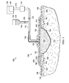
- Figure 1 is a schematic, cross-sectional view of a reduced-pressure treatment system including dressing that utilizes a sealant according to one illustrative embodiment
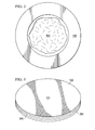
- Figure 2 is a schematic, plan view of the sealant and the wound shown in the embodiment of Figure 1 ;
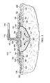
- Figure 3 is a schematic, cross-sectional view of the dressing and the sealant shown in Figure 1 after the sealant has transformed to a gelatinous or liquid state;
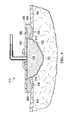
- Figure 4 is a schematic, cross-sectional view of another embodiment of dressing that utilizes a sealant in the reduced-pressure treatment system of Figure 1 ;
- Figure 5 is a schematic, perspective view of a drape, sealant, and release liner for use with dressing of Figure 4 according to one illustrative embodiment.
- reduced pressure generally refers to a pressure less than the ambient pressure at a tissue site that is being subjected to treatment. In most cases, this reduced pressure will be less than the atmospheric pressure at which the patient is located. Alternatively, the reduced pressure may be less than a hydrostatic pressure associated with tissue at the tissue site. Although the terms “vacuum” and “negative pressure” may be used to describe the pressure applied to the tissue site, the actual pressure reduction applied to the tissue site may be significantly less than the pressure reduction normally associated with a complete vacuum. Reduced pressure may initially generate fluid flow in the area of the tissue site. As the hydrostatic pressure around the tissue site approaches the desired reduced pressure, the flow may subside, and the reduced pressure is then maintained. Unless otherwise indicated, values of pressure stated herein are gauge pressures. Similarly, references to increases in reduced pressure typically refer to a decrease in absolute pressure, while decreases in reduced pressure typically refer to an increase in absolute pressure.
- tissue site includes, without limitation, a wound or defect located on or within any tissue, including but not limited to, bone tissue, adipose tissue, muscle tissue, neural tissue, dermal tissue, vascular tissue, connective tissue, cartilage, tendons, or ligaments.
- tissue site may further refer to areas of any tissue that are not necessarily wounded or defective, but are instead areas in which it is desired to add or promote the growth of additional tissue.
- reduced pressure tissue treatment may be used in certain tissue areas to grow additional tissue that may be harvested and transplanted to another tissue location.
- the tissue may be that of any mammal, such as a mouse, rat, rabbit, cat, dog, or primate, including humans, that are being treated as patients.
- the wound at the tissue site may be due to a variety of causes, including trauma, surgery, degeneration, and other causes.
- a reduced pressure treatment system 100 for applying a reduced pressure to a tissue site 101 of a patient according to an illustrative embodiment where the tissue site 101 includes a wound 102 surrounded by healthy tissue including, without limitation, an epidermis 103 of such tissue.
- the system 100 comprises a canister 104 having a filter (not shown) contained within the canister 104 and a fluid supply 106 for delivering a fluid 105 to the tissue site 101.
- the canister 104 is positioned in fluid communication with a reduced pressure source 108 and a reduced pressure dressing 110 that is positioned at the tissue site 101.
- the reduced pressure dressing 110 is fluidly connected to the canister 104 by a conduit 112.
- the conduit 112 may fluidly communicate with the reduced pressure dressing 110 through a tubing adapter 114.
- a second conduit 116 fluidly connects the canister 104 with the reduced pressure source 108.
- the canister 104 may be a fluid reservoir, or collection member, to filter or hold exudates and other fluids removed from the tissue site 101.
- the canister 104 and the reduced pressure source 108 are integrated into a single housing structure.
- the fluid supply 106 is fluidly connected to the reduced pressure dressing 110 by a third conduit 118 that may be connected directly to the reduced pressure dressing 110 (not shown) or indirectly via the conduit 112 which requires valves 122 and 124 for controlling the delivery of reduced pressure from the reduced pressure source 108 and/or the fluid 105 from the fluid supply 106, respectively.
- the fluid 105 may be any gas or liquid, and may contain growth factors, healing factors, or other substances to treat the wound 102 at the tissue site 101.
- the fluid 105 may be air, water, saline, or dye saline.
- the reduced pressure source 108 is an electrically-driven vacuum pump.
- the reduced pressure source 108 may instead be a manually-actuated or manually-charged pump that does not require electrical power.
- the reduced pressure source 108 instead may be any other type of reduced pressure pump, or alternatively a wall suction port such as those available in hospitals and other medical facilities.
- the reduced pressure source 108 may be housed within or used in conjunction with a reduced pressure treatment unit 128, which may also contain sensors, processing units, alarm indicators, memory, databases, software, display unites, and user interfaces that further facilitate the application of reduced pressure treatment to the tissue site 101.
- a sensor or switch may be disposed at or near the reduced pressure source 108 to determine a source pressure generated by the reduced pressure source 108.
- the sensor may communicate with a processing unit that monitors and controls the reduced pressure that is delivered by the reduced pressure source 108.
- the reduced pressure dressing 110 includes a distribution manifold 130 adapted to be positioned at the tissue site 101, and a drape 132 that covers the distribution manifold 130 to maintain reduced pressure beneath the drape 132 at the tissue site 101.
- the drape 132 includes an aperture 134 through which the tubing adapter 114 extends to provide fluid communication between the conduit 112 and the distribution manifold 130.
- the drape 132 further includes a periphery portion 136 that may extend beyond a perimeter of the tissue site 101 and may include an adhesive or bonding agent (not shown) to secure the drape 132 to tissue adjacent the tissue site 101.
- the adhesive disposed on the drape 132 may be used to provide a seal between the epidermis 103 and the drape 132 to prevent leakage of reduced pressure from the tissue site 101.
- a seal layer such as, for example, a hydrogel or other material may be disposed between the drape 132 and the epidermis 103 to augment or substitute for the sealing properties of the adhesive.
- the distribution manifold 130 of the reduced pressure dressing 110 is adapted to contact the tissue site 101.
- the distribution manifold 130 may be partially or fully in contact with the tissue site 101 being treated by the reduced pressure dressing 110.
- the distribution manifold 130 may partially or fully fill the wound 102.
- the distribution manifold 130 may be any size, shape, or thickness depending on a variety of factors, such as the type of treatment being implemented or the nature and size of the tissue site 101 or the wound 102.
- the size and shape of the distribution manifold 130 may be customized by a user to cover a particular portion of the tissue site 101, or to fill or partially fill the tissue site 101 or the wound 102.
- the distribution manifold 130 may have, for example, a square shape, or may be shaped as a circle, oval, polygon, an irregular shape, or any other shape.
- the distribution manifold 130 may further promote granulation at the tissue site 101 when a reduced pressure is applied through the reduced pressure dressing 110.
- any or all of the surfaces of the distribution manifold 130 may have an uneven, coarse, or jagged profile that causes microstrains and stresses at the tissue site 101 when reduced pressure is applied through the distribution manifold 130. These microstrains and stresses have been shown to increase new tissue growth.
- the distribution manifold 130 is a foam material that distributes reduced pressure to the tissue site 101 when the distribution manifold 130 is in contact with or near the tissue site 101.
- the foam material may be either hydrophobic or hydrophilic.
- the distribution manifold 130 is an open-cell, reticulated polyurethane foam such as GranuFoam ® dressing available from Kinetic Concepts, Inc. of San Antonio, Texas.
- the distribution manifold 130 also functions to wick fluid away from the tissue site 101, while continuing to provide reduced pressure to the tissue site 101 as a manifold.
- the wicking properties of the distribution manifold 130 draw fluid away from the tissue site 101 by capillary flow or other wicking mechanisms.
- a hydrophilic foam is a polyvinyl alcohol, open-cell foam such as V.A.C. WhiteFoam ® dressing available from Kinetic Concepts, Inc. of San Antonio, Texas.
- Other hydrophilic foams may include those made from polyether.
- Other foams that may exhibit hydrophilic characteristics include hydrophobic foams that have been treated or coated to provide hydrophilicity.
- the distribution manifold 130 may be constructed from bioresorbable materials that do not have to be removed from a patient's body following use of the reduced pressure dressing 110.
- Suitable bioresorbable materials may include, without limitation, a polymeric blend of polylactic acid (PLA) and polyglycolic acid (PGA).
- the polymeric blend may also include, without limitation, polycarbonates, polyfumarates, and capralactones.
- the distribution manifold 130 may further serve as a scaffold for new cell-growth, or a scaffold material may be used in conjunction with the distribution manifold 130 to promote cell-growth.
- a scaffold is a substance or structure used to enhance or promote the growth of cells or formation of tissue, such as a three-dimensional porous structure that provides a template for cell growth.
- Illustrative examples of scaffold materials include calcium phosphate, collagen, PLA/PGA, coral hydroxy apatites, carbonates, or processed allograft materials.
- the drape 132 may be any material that provides a pneumatic or fluid seal.
- the drape 132 may, for example, be an impermeable or semi-permeable, elastomeric material.
- "Elastomeric” means having the properties of an elastomer, and generally refers to a polymeric material that has rubber-like properties. More specifically, most elastomers have elongation rates greater than 100% and a significant amount of resilience. The resilience of a material refers to the material's ability to recover from an elastic deformation.
- elastomers may include, but are not limited to, natural rubbers, polyisoprene, styrene butadiene rubber, chloroprene rubber, polybutadiene, nitrile rubber, butyl rubber, ethylene propylene rubber, ethylene propylene diene monomer, chlorosulfonated polyethylene, polysulfide rubber, polyurethane, EVA film, co-polyester, and silicones.
- drape materials include a silicone drape, 3M Tegaderm ® drape, acrylic drape such as one available from Avery Dennison, or an incise drape.
- the reduced pressure dressing 110 further includes a seal 140 that is generally annular in shape and disposed between the tissue site 101 and the drape 132 thereby having a tissue-facing side 142 and a drape-facing side 144 when positioned on the tissue site 101.
- the drape 132 covers the seal 140 such that the periphery portion 136 of the drape 132 extends beyond the seal 140 so that the adhesive portion of the drape 132 adheres to the tissue surrounding the wound 102 at the tissue site 101.
- the seal 140 is substantially solid in form and substantially surrounds the wound 102 so that the tissue-facing side 142 is positioned adjacent the epidermis 103 of the tissue site 101.
- the epidermis 103 may have recesses and cracks or other discontinuities on the surface, i.e., epidermal discontinuities 150, extending beyond the periphery portion 136. These epidermal discontinuities 150 form passages 152 through which air from outside the reduced pressure dressing 110 ("external air”) may leak into the tissue site 101 when reduced pressure is delivered to the distribution manifold 130.
- folds or buckles in the drape 132 may also form the passages 152 through which external air may leak into the tissue site 101 when reduced pressure is delivered to the distribution manifold 130.
- the seal 140 is initially solid in form that is made from material adapted to react with fluid such as, for example, the flow of external air as indicated by arrows 155.
- This reaction transforms the seal 140 from solid phase to either liquid or gel which flows or expands to fill the passages 152 created by the epidermal discontinuities 150 and/or the drape discontinuities 154. Consequently, the transformed seal 140 forms a sealant 160 that fills the passages 152 and prevents the external air from leaking into the tissue site 101 when reduced pressure is delivered to the distribution manifold 130.
- the sealant 160 substantially blocks the passages 152 to prevent the external air from being drawn into the wound 102 by the reduced pressure, thereby maintaining the level of reduced pressure being delivered by the distribution manifold 130 to the tissue site 101.
- the seal 140 may be fabricated from a material containing isocyanate that reacts with water vapor content of the external air to create carbon dioxide gas within the material causing the material to expand and fill the passages 152 forming the sealant 160 that plugs the passages 152 created by the epidermal discontinuities 150 and the drape discontinuities 154.
- Water-sensitive polymers may also be used to form the seal 140.
- the seal 140 may be formed from an uncrosslinked water-sensitive polymer to liquify when exposed to moisture.
- the seal 140 may also be formed from a crosslinked water-sensitive polymer to swell when exposed to moisture.
- Water-sensitive polymers include polyacrylates, polyvinylpyrrolidone, polyvinyl alcohol, alginates, and carboxymethyl cellulose.
- the seal 140 may be formed from water-sensitive materials that liberate gases such as metal hydrides and carbides. Further, hygroscopic materials, such as anhydrides, may be used to form the seal 140 some of which may also increase in volume as moisture is absorbed.
- the transformation of a water-sensitive seal 140 to form the sealant 160 may be initiated or accelerated by first using a sponge or other application device to wet the surfaces of the seal 140 with water. Further transformation results when the water vapor content of the external air reacts with the water-sensitive material being utilized for the seal 140.
- the fluid supply 106 may provide the fluid 105 to the tissue site 101 via the distribution manifold 130 as described above and further indicated by arrows 164 wherein the fluid 105 includes an agent that facilitates the transformation of the seal 140 into the sealant 160 when exposed to the leakage of external air that comes in contact with the seal 140.
- the fluid supply 106 may provide the fluid 105 to the tissue site 101 via the distribution manifold 130 as described above and further indicated by the arrows 164 wherein the fluid 105 includes an agent that causes the transformation of the seal 140 into the sealant 160 without being exposed to the leakage of external air that comes in contact with the seal 140.
- solvents may be introduced as solutions that cause the seal 140 to liquefy or swell.
- the transformation of a water-sensitive seal 140 to form the sealant 160 may be initiated or accelerated by first using a sponge or other application device to wet the surfaces of the seal 140 with either water or the solvent.
- solvents examples include alcohols, glycols, polyethylene glycols, and glycerine that react with a seal 140 that is fabricated from materials such as modified polyurethanes, acrylics, and acetates.
- Other solvents, incompatible with water, may also be used and introduced as emulsions or dispersions that are absorbed by the seal 140 which liquefies or swells as a result of the reaction.
- these water-incompatible solvents include esters, phthalates, trimellitates, citrates, and vegetable oils.
- the seal 140 may also be formed from polyurethane that contains an active substance that expands upon contact with the fluid 105.
- the polyurethane may also function as an adhesive so that the sealant 160 adheres more tightly to the drape 132 and the patient's epidermis 103.
- the seal 140 may also include isocyanate, tartaric acid and sodium bicarbonate, super absorbent fiber that expands when exposed to a fluid, or water-absorbing polymers that swell when exposed to a fluid.
- the fiber may form a mesh such that the fibers are oriented along at least two directions and intersect with one another.
- the expansion of the seal 140 may be caused by the formation of bubbles within the seal 140 after it transforms into the sealant 160. These bubbles may be caused by the release of carbon dioxide upon contact between the seal 140 and the fluid 105.
- the specific material used for the seal 140 may depend upon the manner in which the expansion of the seal 140 is activated. Also, the shape of the seal 140 can vary depending on the manner in which the seal 140 is used or applied.
- the expansion of the seal 140 can be activated using any of a variety of mechanisms depending on the embodiment employed, and several non-limiting examples follow.
- the seal 140 expands in the presence of the fluid 105 delivered from the fluid supply 106 via the distribution manifold 130 as indicated by the arrows 164 in Figure 3 .
- the fluid 105 flows through the distribution manifold 130 and contacts the seal 140 causing it to expand to fill the passages 152 created by the epidermal discontinuities 150 and the drape discontinuities 154 as described above.
- the fluid 105 may continue to be supplied to the sealant 160 after the expansion of the seal 140 to provide therapy to the wound 102.
- the fluid used to activate and expand the seal 140 may originate from sources other than the fluid supply 106.
- the fluid supplied to the seal 140 may be exudate from the wound 102.
- the exudate flows to the seal 140 as indicated by exudate flow arrows 157.
- fluid may be supplied to the seal 140 by pre-applying the fluid to the tissue site 101 with a sponge or other application device and, more specifically, the surface layer of the epidermis 103, before applying the reduced pressure dressing 110 to the tissue site 101.
- This pre-applied fluid may be a gel or liquid sufficient to activate the expansion of the seal 140.
- a fluid may be applied to the seal 140 from under the periphery portion 136 of the drape 132 after the reduced pressure dressing 110 has been applied to the tissue site 101.
- the fluid may be sprayed, injected, or otherwise applied onto or into the seal 140 by a care giver, including the patient.
- the care giver may desire to expose all or a substantial portion of the seal 140 to the fluid, the care giver may also apply the fluid to targeted regions of the seal 140 based on an assessment of the areas in the reduced pressure dressing 110 where the passages 152 are detected. Using this technique, a care giver may determine the areas at which a fluid lead exists in the reduced pressure dressing 110, and apply the fluid to those portions of the seal 140 that are adjacent the passages 152.
- reduced pressure may be applied to the distribution manifold 130 so that the external air is drawn to the seal 140 from the outside of the reduced pressure dressing 110 through the passages 152 as described above and as indicated by the arrows 155.
- the seal 140 may be formed from material that reacts with the air or component thereof.
- the seal 140 may react with oxygen, carbon dioxide, or other component of the gas to cause the expansion of the seal 140.
- the seal 140 may be formed from material that reacts to gases other than air that may be externally injected into the passages 152 causing the seal 140 to expand.
- Examples of materials that increase in volume when absorbing a gas include iron that reacts with oxygen to form iron oxide (Fe 2 O 3 ), and zinc oxide that reacts with carbon dioxide to form zinc carbonate. Amines and alcohol amines may also be used in the seal 140 to absorb carbon dioxide.
- reduced pressure can be applied to the distribution manifold 130 to create a pressure differential under the drape 132 of sufficient magnitude to cause the expansion of the seal 140.
- the seal 140 is formed from a material that expands when a pressure drop exists across the length of the material.
- the seal 140 may be a composition comprising a material containing polymer spheres or bubbles (e.g., Expancel ® from Akzo Nobel N.V. located at Strawinskylaan 2555, 1077 ZZ Amsterdam, Postbus 75730) that are filled with low boiling point liquids. Upon heating, the polymer softens and the spheres expand so that the seal 140 fills any of the passages 152.
- the polymer spheres may soften into an elastic state without a significant change in the internal pressure or the corresponding size of the spheres.
- the elastic spheres When a reduced pressure is applied to the seal 140, however, the elastic spheres are subjected to a pressure differential causing them to expand so that the seal 140 fills the passages 152.
- the pressure differential may be increased further causing the spheres to expand and ultimately rupture releasing their contents, such as gels or adhesives, to fill any of the passages 152 and bind the spheres together to form a tighter seal.
- the exposed contents may be oxygen sensitive and harden over a period of time to increase the stability of the seal.
- the seal 140 and the drape 132 may be applied to the tissue site 101 as a unit, or a care giver can cover the seal 140 with the drape 132 after the seal 140 has been applied.
- the care giver may insert all or a portion of the seal 140 under the periphery portion 136 of the drape 132 after the drape 132 has been applied to the tissue site 101.
- a reduced pressure dressing 210 is shown that includes the drape 132, a seal 240 (as shown in Figure 5 ) and the distribution manifold 130.
- the drape 132 includes a first side 250 and a second, tissue-facing side 252.
- the seal 240 is different from the seal 140 of Figure 1 only in shape which covers a substantial portion of the second, tissue-facing side 252 of the drape 132.
- the sealant 260 covers a larger surface area of the epidermis 103 to plug more of the passages 152 (not shown) resulting from the epidermal discontinuities 150 and drape discontinuities (not shown) as described above.
- Using a sealant that covers a larger area of contact between the drape 132 and the epidermis 103 may further reduce the number and severity of the passages 152 caused by both discontinuities.
- a release liner 254 as shown in Figure 5 may be utilized to cover a tissue-facing side 212 of the seal 240, prior to application of the reduced pressure dressing 210 to the tissue site 101.
- the release liner 254 preserves the adhesiveness of the seal 240 prior to the seal's 240 contact with the epidermis 103.
- the release liner 254 also prevents fluid from contacting the seal 240 prior to application of the reduced pressure dressing 210 to the tissue site 101.
- the release liner 254 may be formed from any gas or liquid impermeable material to prevent the seal 240 from being contaminated or from transforming to a gelatinous or liquid state before being applied to the tissue site 101.
- the release liner 254 may also have tabs (not shown) so that a care giver can easily peel the release liner 254 from the seal 240 when desired.
- the seal 240 may be inserted in separate pieces between the drape 132 and the epidermis 103 after the reduced pressure dressing 110 is applied to the tissue site 101.
- the drape 132 may be applied to the tissue site 101 and held in place by an adhesive (not shown) that may also function as a sealant.
- the peripheral portion of the drape 132 is free from adhesive to leave a space for inserting pieces of the seal 240 between the drape 132 and the epidermis 103 to plug any of the passages 152 that may be detected after reduced pressure is applied to the wound 102.
- the separate pieces of the seal 240 do not need to be annular in shape as shown in Figures 1 and 4 , but rather may be whatever shape necessary to plug the passages 152 that is detected.
- the separate piece or pieces of seal 240 are inserted under the drape 132 at the desired location and then exposed to any of the stimuli described above, e.g., reduced pressure or fluids, to transform the seal to the sealant 160, 260 as shown in Figures 3 and 4 , respectively.
Landscapes
- Health & Medical Sciences (AREA)
- Heart & Thoracic Surgery (AREA)
- General Health & Medical Sciences (AREA)
- Veterinary Medicine (AREA)
- Engineering & Computer Science (AREA)
- Public Health (AREA)
- Life Sciences & Earth Sciences (AREA)
- Animal Behavior & Ethology (AREA)
- Vascular Medicine (AREA)
- Biomedical Technology (AREA)
- Hematology (AREA)
- Anesthesiology (AREA)
- Dermatology (AREA)
- Chemical & Material Sciences (AREA)
- Materials Engineering (AREA)
- Epidemiology (AREA)
- Media Introduction/Drainage Providing Device (AREA)
- Materials For Medical Uses (AREA)
- Surgical Instruments (AREA)
- External Artificial Organs (AREA)
Abstract
Description
- The present invention claims the benefit, under 35 USC § 119(e), of the filing of
U.S. Provisional Patent Application serial number 61/242,488 - The present invention relates generally to medical treatment systems, and more particularly, medical dressings, systems, and methods employing sealants.
- Clinical studies and practice have shown that providing a reduced pressure in proximity to a tissue site augments and accelerates the growth of new tissue at the tissue site. The applications of this phenomenon are numerous, but application of reduced pressure has been particularly successful in treating wounds. This treatment (frequently referred to in the medical community as "negative pressure wound therapy," "reduced pressure therapy," or "vacuum therapy") provides a number of benefits, which may include faster healing and increased formulation of granulation tissue. Unless otherwise indicated, as used herein, "or" does not require mutual exclusivity.
- According to an illustrative embodiment, a system for treating a wound at a tissue site of a patient comprising a reduced-pressure source to supply reduced pressure, a drape adhering to the tissue site to cover the wound where possible leak passages between the drape and tissue site may occur, and a seal disposed between the drape and the tissue site, is disclosed. The seal is adapted to react with a fluid to form a sealant substantially filling the passages in response to air leaking through the passages from outside the drape when reduced pressure is applied to the wound.
- According to another illustrative embodiment, an apparatus includes a seal having a first side and a second, tissue-facing side. The seal is adapted for placement adjacent the tissue site and is operable to expand in a presence of a fluid to form a substantially sealed space at the tissue site. The apparatus also includes a drape for covering the sealant and further forming the substantially sealed space.
- According to another illustrative embodiment, a method for sealing a drape to a tissue site for treating a wound at the tissue site comprising applying the drape to cover the tissue site whereby passages are formed between the drape and the tissue site, positioning a seal between the drape and the tissue site wherein the seal is adapted to react with a fluid to form a sealant for substantially filling the passages, is also disclosed.
-
Figure 1 is a schematic, cross-sectional view of a reduced-pressure treatment system including dressing that utilizes a sealant according to one illustrative embodiment; -
Figure 2 is a schematic, plan view of the sealant and the wound shown in the embodiment ofFigure 1 ; -
Figure 3 is a schematic, cross-sectional view of the dressing and the sealant shown inFigure 1 after the sealant has transformed to a gelatinous or liquid state; -
Figure 4 is a schematic, cross-sectional view of another embodiment of dressing that utilizes a sealant in the reduced-pressure treatment system ofFigure 1 ; and -
Figure 5 is a schematic, perspective view of a drape, sealant, and release liner for use with dressing ofFigure 4 according to one illustrative embodiment. - In the following detailed description of the illustrative embodiments, reference is made to the accompanying drawings that form a part hereof. These embodiments are described in sufficient detail to enable those skilled in the art to practice the invention, and it is understood that other embodiments may be utilized and that logical structural, mechanical, electrical, and chemical changes may be made without departing from the spirit or scope of the invention. To avoid detail not necessary to enable those skilled in the art to practice the embodiments described herein, the description may omit certain information known to those skilled in the art. The following detailed description is, therefore, not to be taken in a limiting sense, and the scope of the illustrative embodiments are defined only by the appended claims.
- The term "reduced pressure" as used herein generally refers to a pressure less than the ambient pressure at a tissue site that is being subjected to treatment. In most cases, this reduced pressure will be less than the atmospheric pressure at which the patient is located. Alternatively, the reduced pressure may be less than a hydrostatic pressure associated with tissue at the tissue site. Although the terms "vacuum" and "negative pressure" may be used to describe the pressure applied to the tissue site, the actual pressure reduction applied to the tissue site may be significantly less than the pressure reduction normally associated with a complete vacuum. Reduced pressure may initially generate fluid flow in the area of the tissue site. As the hydrostatic pressure around the tissue site approaches the desired reduced pressure, the flow may subside, and the reduced pressure is then maintained. Unless otherwise indicated, values of pressure stated herein are gauge pressures. Similarly, references to increases in reduced pressure typically refer to a decrease in absolute pressure, while decreases in reduced pressure typically refer to an increase in absolute pressure.
- The term "tissue site" as used herein includes, without limitation, a wound or defect located on or within any tissue, including but not limited to, bone tissue, adipose tissue, muscle tissue, neural tissue, dermal tissue, vascular tissue, connective tissue, cartilage, tendons, or ligaments. The term "tissue site" may further refer to areas of any tissue that are not necessarily wounded or defective, but are instead areas in which it is desired to add or promote the growth of additional tissue. For example, reduced pressure tissue treatment may be used in certain tissue areas to grow additional tissue that may be harvested and transplanted to another tissue location. The tissue may be that of any mammal, such as a mouse, rat, rabbit, cat, dog, or primate, including humans, that are being treated as patients. Also, the wound at the tissue site may be due to a variety of causes, including trauma, surgery, degeneration, and other causes.
- Referring to
Figures 1 and2 , a reducedpressure treatment system 100 for applying a reduced pressure to atissue site 101 of a patient according to an illustrative embodiment where thetissue site 101 includes awound 102 surrounded by healthy tissue including, without limitation, anepidermis 103 of such tissue. Thesystem 100 comprises acanister 104 having a filter (not shown) contained within thecanister 104 and afluid supply 106 for delivering afluid 105 to thetissue site 101. Thecanister 104 is positioned in fluid communication with a reducedpressure source 108 and a reducedpressure dressing 110 that is positioned at thetissue site 101. The reducedpressure dressing 110 is fluidly connected to thecanister 104 by aconduit 112. Theconduit 112 may fluidly communicate with the reducedpressure dressing 110 through atubing adapter 114. Asecond conduit 116 fluidly connects thecanister 104 with the reducedpressure source 108. - The
canister 104 may be a fluid reservoir, or collection member, to filter or hold exudates and other fluids removed from thetissue site 101. In one embodiment, thecanister 104 and the reducedpressure source 108 are integrated into a single housing structure. Thefluid supply 106 is fluidly connected to the reducedpressure dressing 110 by athird conduit 118 that may be connected directly to the reduced pressure dressing 110 (not shown) or indirectly via theconduit 112 which requiresvalves pressure source 108 and/or thefluid 105 from thefluid supply 106, respectively. Thefluid 105 may be any gas or liquid, and may contain growth factors, healing factors, or other substances to treat thewound 102 at thetissue site 101. For example, thefluid 105 may be air, water, saline, or dye saline. - In the embodiment illustrated in
Figure 1 , the reducedpressure source 108 is an electrically-driven vacuum pump. In another implementation, the reducedpressure source 108 may instead be a manually-actuated or manually-charged pump that does not require electrical power. The reducedpressure source 108 instead may be any other type of reduced pressure pump, or alternatively a wall suction port such as those available in hospitals and other medical facilities. The reducedpressure source 108 may be housed within or used in conjunction with a reducedpressure treatment unit 128, which may also contain sensors, processing units, alarm indicators, memory, databases, software, display unites, and user interfaces that further facilitate the application of reduced pressure treatment to thetissue site 101. In one example, a sensor or switch (not shown) may be disposed at or near the reducedpressure source 108 to determine a source pressure generated by the reducedpressure source 108. The sensor may communicate with a processing unit that monitors and controls the reduced pressure that is delivered by the reducedpressure source 108. - The reduced
pressure dressing 110 includes adistribution manifold 130 adapted to be positioned at thetissue site 101, and adrape 132 that covers thedistribution manifold 130 to maintain reduced pressure beneath thedrape 132 at thetissue site 101. Thedrape 132 includes anaperture 134 through which thetubing adapter 114 extends to provide fluid communication between theconduit 112 and thedistribution manifold 130. Thedrape 132 further includes aperiphery portion 136 that may extend beyond a perimeter of thetissue site 101 and may include an adhesive or bonding agent (not shown) to secure thedrape 132 to tissue adjacent thetissue site 101. In one embodiment, the adhesive disposed on thedrape 132 may be used to provide a seal between theepidermis 103 and thedrape 132 to prevent leakage of reduced pressure from thetissue site 101. In another embodiment, a seal layer (not shown) such as, for example, a hydrogel or other material may be disposed between thedrape 132 and theepidermis 103 to augment or substitute for the sealing properties of the adhesive. - The
distribution manifold 130 of the reducedpressure dressing 110 is adapted to contact thetissue site 101. Thedistribution manifold 130 may be partially or fully in contact with thetissue site 101 being treated by the reducedpressure dressing 110. When thedistribution manifold 130 is in contact with thewound 102 at thetissue site 101, thedistribution manifold 130 may partially or fully fill thewound 102. Thedistribution manifold 130 may be any size, shape, or thickness depending on a variety of factors, such as the type of treatment being implemented or the nature and size of thetissue site 101 or thewound 102. For example, the size and shape of thedistribution manifold 130 may be customized by a user to cover a particular portion of thetissue site 101, or to fill or partially fill thetissue site 101 or thewound 102. Thedistribution manifold 130 may have, for example, a square shape, or may be shaped as a circle, oval, polygon, an irregular shape, or any other shape. Thedistribution manifold 130 may further promote granulation at thetissue site 101 when a reduced pressure is applied through the reduced pressure dressing 110. For example, any or all of the surfaces of thedistribution manifold 130 may have an uneven, coarse, or jagged profile that causes microstrains and stresses at thetissue site 101 when reduced pressure is applied through thedistribution manifold 130. These microstrains and stresses have been shown to increase new tissue growth. - In one illustrative embodiment, the
distribution manifold 130 is a foam material that distributes reduced pressure to thetissue site 101 when thedistribution manifold 130 is in contact with or near thetissue site 101. The foam material may be either hydrophobic or hydrophilic. In one non-limiting example, thedistribution manifold 130 is an open-cell, reticulated polyurethane foam such as GranuFoam® dressing available from Kinetic Concepts, Inc. of San Antonio, Texas. In the example in which thedistribution manifold 130 is made from a hydrophilic material, thedistribution manifold 130 also functions to wick fluid away from thetissue site 101, while continuing to provide reduced pressure to thetissue site 101 as a manifold. The wicking properties of thedistribution manifold 130 draw fluid away from thetissue site 101 by capillary flow or other wicking mechanisms. An example of a hydrophilic foam is a polyvinyl alcohol, open-cell foam such as V.A.C. WhiteFoam® dressing available from Kinetic Concepts, Inc. of San Antonio, Texas. Other hydrophilic foams may include those made from polyether. Other foams that may exhibit hydrophilic characteristics include hydrophobic foams that have been treated or coated to provide hydrophilicity. - In one embodiment, the
distribution manifold 130 may be constructed from bioresorbable materials that do not have to be removed from a patient's body following use of the reduced pressure dressing 110. Suitable bioresorbable materials may include, without limitation, a polymeric blend of polylactic acid (PLA) and polyglycolic acid (PGA). The polymeric blend may also include, without limitation, polycarbonates, polyfumarates, and capralactones. Thedistribution manifold 130 may further serve as a scaffold for new cell-growth, or a scaffold material may be used in conjunction with thedistribution manifold 130 to promote cell-growth. A scaffold is a substance or structure used to enhance or promote the growth of cells or formation of tissue, such as a three-dimensional porous structure that provides a template for cell growth. Illustrative examples of scaffold materials include calcium phosphate, collagen, PLA/PGA, coral hydroxy apatites, carbonates, or processed allograft materials. - The
drape 132 may be any material that provides a pneumatic or fluid seal. Thedrape 132 may, for example, be an impermeable or semi-permeable, elastomeric material. "Elastomeric" means having the properties of an elastomer, and generally refers to a polymeric material that has rubber-like properties. More specifically, most elastomers have elongation rates greater than 100% and a significant amount of resilience. The resilience of a material refers to the material's ability to recover from an elastic deformation. Examples of elastomers may include, but are not limited to, natural rubbers, polyisoprene, styrene butadiene rubber, chloroprene rubber, polybutadiene, nitrile rubber, butyl rubber, ethylene propylene rubber, ethylene propylene diene monomer, chlorosulfonated polyethylene, polysulfide rubber, polyurethane, EVA film, co-polyester, and silicones. Specific examples of drape materials include a silicone drape, 3M Tegaderm® drape, acrylic drape such as one available from Avery Dennison, or an incise drape. - The reduced pressure dressing 110 further includes a
seal 140 that is generally annular in shape and disposed between thetissue site 101 and thedrape 132 thereby having a tissue-facingside 142 and a drape-facingside 144 when positioned on thetissue site 101. Thedrape 132 covers theseal 140 such that theperiphery portion 136 of thedrape 132 extends beyond theseal 140 so that the adhesive portion of thedrape 132 adheres to the tissue surrounding thewound 102 at thetissue site 101. Theseal 140 is substantially solid in form and substantially surrounds thewound 102 so that the tissue-facingside 142 is positioned adjacent theepidermis 103 of thetissue site 101. Even though theperiphery portion 136 of thedrape 132 functions as an adhesive with some sealing capability as described above, theepidermis 103 may have recesses and cracks or other discontinuities on the surface, i.e.,epidermal discontinuities 150, extending beyond theperiphery portion 136. Theseepidermal discontinuities 150form passages 152 through which air from outside the reduced pressure dressing 110 ("external air") may leak into thetissue site 101 when reduced pressure is delivered to thedistribution manifold 130. Additionally, when thedrape 132 is positioned on thetissue site 101, folds or buckles in thedrape 132, i.e., drapediscontinuities 154, may also form thepassages 152 through which external air may leak into thetissue site 101 when reduced pressure is delivered to thedistribution manifold 130. - Referring to
Figures 1 and3 , theseal 140 is initially solid in form that is made from material adapted to react with fluid such as, for example, the flow of external air as indicated byarrows 155. This reaction transforms theseal 140 from solid phase to either liquid or gel which flows or expands to fill thepassages 152 created by theepidermal discontinuities 150 and/or thedrape discontinuities 154. Consequently, the transformedseal 140 forms asealant 160 that fills thepassages 152 and prevents the external air from leaking into thetissue site 101 when reduced pressure is delivered to thedistribution manifold 130. Thesealant 160 substantially blocks thepassages 152 to prevent the external air from being drawn into thewound 102 by the reduced pressure, thereby maintaining the level of reduced pressure being delivered by thedistribution manifold 130 to thetissue site 101. - The
seal 140 may be fabricated from a material containing isocyanate that reacts with water vapor content of the external air to create carbon dioxide gas within the material causing the material to expand and fill thepassages 152 forming thesealant 160 that plugs thepassages 152 created by theepidermal discontinuities 150 and thedrape discontinuities 154. Water-sensitive polymers may also be used to form theseal 140. For example, theseal 140 may be formed from an uncrosslinked water-sensitive polymer to liquify when exposed to moisture. Theseal 140 may also be formed from a crosslinked water-sensitive polymer to swell when exposed to moisture. Water-sensitive polymers include polyacrylates, polyvinylpyrrolidone, polyvinyl alcohol, alginates, and carboxymethyl cellulose. In another example, theseal 140 may be formed from water-sensitive materials that liberate gases such as metal hydrides and carbides. Further, hygroscopic materials, such as anhydrides, may be used to form theseal 140 some of which may also increase in volume as moisture is absorbed. The transformation of a water-sensitive seal 140 to form thesealant 160 may be initiated or accelerated by first using a sponge or other application device to wet the surfaces of theseal 140 with water. Further transformation results when the water vapor content of the external air reacts with the water-sensitive material being utilized for theseal 140. - In another embodiment, the
fluid supply 106 may provide the fluid 105 to thetissue site 101 via thedistribution manifold 130 as described above and further indicated byarrows 164 wherein the fluid 105 includes an agent that facilitates the transformation of theseal 140 into thesealant 160 when exposed to the leakage of external air that comes in contact with theseal 140. In another embodiment, thefluid supply 106 may provide the fluid 105 to thetissue site 101 via thedistribution manifold 130 as described above and further indicated by thearrows 164 wherein the fluid 105 includes an agent that causes the transformation of theseal 140 into thesealant 160 without being exposed to the leakage of external air that comes in contact with theseal 140. For example, solvents may be introduced as solutions that cause theseal 140 to liquefy or swell. As described above, the transformation of a water-sensitive seal 140 to form thesealant 160 may be initiated or accelerated by first using a sponge or other application device to wet the surfaces of theseal 140 with either water or the solvent. - Examples of solvents that may be used include alcohols, glycols, polyethylene glycols, and glycerine that react with a
seal 140 that is fabricated from materials such as modified polyurethanes, acrylics, and acetates. Other solvents, incompatible with water, may also be used and introduced as emulsions or dispersions that are absorbed by theseal 140 which liquefies or swells as a result of the reaction. Examples of these water-incompatible solvents include esters, phthalates, trimellitates, citrates, and vegetable oils. Theseal 140 may also be formed from polyurethane that contains an active substance that expands upon contact with thefluid 105. The polyurethane may also function as an adhesive so that thesealant 160 adheres more tightly to thedrape 132 and the patient'sepidermis 103. - In another embodiment, the
seal 140 may also include isocyanate, tartaric acid and sodium bicarbonate, super absorbent fiber that expands when exposed to a fluid, or water-absorbing polymers that swell when exposed to a fluid. In the example in which theseal 140 is formed from a fiber, the fiber may form a mesh such that the fibers are oriented along at least two directions and intersect with one another. In one embodiment, the expansion of theseal 140 may be caused by the formation of bubbles within theseal 140 after it transforms into thesealant 160. These bubbles may be caused by the release of carbon dioxide upon contact between theseal 140 and thefluid 105. The specific material used for theseal 140 may depend upon the manner in which the expansion of theseal 140 is activated. Also, the shape of theseal 140 can vary depending on the manner in which theseal 140 is used or applied. - The expansion of the
seal 140 can be activated using any of a variety of mechanisms depending on the embodiment employed, and several non-limiting examples follow. In one example, as discussed above, theseal 140 expands in the presence of the fluid 105 delivered from thefluid supply 106 via thedistribution manifold 130 as indicated by thearrows 164 inFigure 3 . The fluid 105 flows through thedistribution manifold 130 and contacts theseal 140 causing it to expand to fill thepassages 152 created by theepidermal discontinuities 150 and thedrape discontinuities 154 as described above. The fluid 105 may continue to be supplied to thesealant 160 after the expansion of theseal 140 to provide therapy to thewound 102. - The fluid used to activate and expand the
seal 140 may originate from sources other than thefluid supply 106. In one embodiment, the fluid supplied to theseal 140 may be exudate from thewound 102. In this example, the exudate flows to theseal 140 as indicated byexudate flow arrows 157. In another example, fluid may be supplied to theseal 140 by pre-applying the fluid to thetissue site 101 with a sponge or other application device and, more specifically, the surface layer of theepidermis 103, before applying the reduced pressure dressing 110 to thetissue site 101. This pre-applied fluid may be a gel or liquid sufficient to activate the expansion of theseal 140. In yet another example, a fluid may be applied to theseal 140 from under theperiphery portion 136 of thedrape 132 after the reduced pressure dressing 110 has been applied to thetissue site 101. In this example the fluid may be sprayed, injected, or otherwise applied onto or into theseal 140 by a care giver, including the patient. Although the care giver may desire to expose all or a substantial portion of theseal 140 to the fluid, the care giver may also apply the fluid to targeted regions of theseal 140 based on an assessment of the areas in the reduced pressure dressing 110 where thepassages 152 are detected. Using this technique, a care giver may determine the areas at which a fluid lead exists in the reduced pressure dressing 110, and apply the fluid to those portions of theseal 140 that are adjacent thepassages 152. - In another example of a mechanism by which the
seal 140 may be exposed to a fluid, reduced pressure may be applied to thedistribution manifold 130 so that the external air is drawn to theseal 140 from the outside of the reduced pressure dressing 110 through thepassages 152 as described above and as indicated by thearrows 155. When contacting theseal 140, the vapor or humidity within the air reacts with theseal 140 as described above. Theseal 140 may be formed from material that reacts with the air or component thereof. For example, theseal 140 may react with oxygen, carbon dioxide, or other component of the gas to cause the expansion of theseal 140. In another embodiment, theseal 140 may be formed from material that reacts to gases other than air that may be externally injected into thepassages 152 causing theseal 140 to expand. Examples of materials that increase in volume when absorbing a gas include iron that reacts with oxygen to form iron oxide (Fe2O3), and zinc oxide that reacts with carbon dioxide to form zinc carbonate. Amines and alcohol amines may also be used in theseal 140 to absorb carbon dioxide. - In yet another example, reduced pressure can be applied to the
distribution manifold 130 to create a pressure differential under thedrape 132 of sufficient magnitude to cause the expansion of theseal 140. In this example, theseal 140 is formed from a material that expands when a pressure drop exists across the length of the material. In one embodiment, theseal 140 may be a composition comprising a material containing polymer spheres or bubbles (e.g., Expancel® from Akzo Nobel N.V. located at Strawinskylaan 2555, 1077 ZZ Amsterdam, Postbus 75730) that are filled with low boiling point liquids. Upon heating, the polymer softens and the spheres expand so that theseal 140 fills any of thepassages 152. Alternatively, the polymer spheres may soften into an elastic state without a significant change in the internal pressure or the corresponding size of the spheres. When a reduced pressure is applied to theseal 140, however, the elastic spheres are subjected to a pressure differential causing them to expand so that theseal 140 fills thepassages 152. The pressure differential may be increased further causing the spheres to expand and ultimately rupture releasing their contents, such as gels or adhesives, to fill any of thepassages 152 and bind the spheres together to form a tighter seal. Also, the exposed contents may be oxygen sensitive and harden over a period of time to increase the stability of the seal. - The
seal 140 and thedrape 132 may be applied to thetissue site 101 as a unit, or a care giver can cover theseal 140 with thedrape 132 after theseal 140 has been applied. In another embodiment, the care giver may insert all or a portion of theseal 140 under theperiphery portion 136 of thedrape 132 after thedrape 132 has been applied to thetissue site 101. By inserting theseal 140 to the reduced pressure dressing 110 after the reduced pressure dressing 110 has been applied to thetissue site 101, theseal 140 may be used in conjunction with existing wound dressings. - Referring now to
Figures 4 and5 , a reduced pressure dressing 210 is shown that includes thedrape 132, a seal 240 (as shown inFigure 5 ) and thedistribution manifold 130. Thedrape 132 includes afirst side 250 and a second, tissue-facingside 252. Theseal 240 is different from theseal 140 ofFigure 1 only in shape which covers a substantial portion of the second, tissue-facingside 252 of thedrape 132. When theseal 240 transforms to a gelatinous or liquid state to form asealant 260 as shown inFigure 4 , thesealant 260 covers a larger surface area of theepidermis 103 to plug more of the passages 152 (not shown) resulting from theepidermal discontinuities 150 and drape discontinuities (not shown) as described above. Using a sealant that covers a larger area of contact between thedrape 132 and theepidermis 103 may further reduce the number and severity of thepassages 152 caused by both discontinuities. - A
release liner 254 as shown inFigure 5 may be utilized to cover a tissue-facingside 212 of theseal 240, prior to application of the reduced pressure dressing 210 to thetissue site 101. Therelease liner 254 preserves the adhesiveness of theseal 240 prior to the seal's 240 contact with theepidermis 103. Therelease liner 254 also prevents fluid from contacting theseal 240 prior to application of the reduced pressure dressing 210 to thetissue site 101. Therelease liner 254 may be formed from any gas or liquid impermeable material to prevent theseal 240 from being contaminated or from transforming to a gelatinous or liquid state before being applied to thetissue site 101. Therelease liner 254 may also have tabs (not shown) so that a care giver can easily peel therelease liner 254 from theseal 240 when desired. - In an alternative embodiment, the
seal 240 may be inserted in separate pieces between thedrape 132 and theepidermis 103 after the reduced pressure dressing 110 is applied to thetissue site 101. Thedrape 132 may be applied to thetissue site 101 and held in place by an adhesive (not shown) that may also function as a sealant. The peripheral portion of thedrape 132 is free from adhesive to leave a space for inserting pieces of theseal 240 between thedrape 132 and theepidermis 103 to plug any of thepassages 152 that may be detected after reduced pressure is applied to thewound 102. The separate pieces of theseal 240 do not need to be annular in shape as shown inFigures 1 and4 , but rather may be whatever shape necessary to plug thepassages 152 that is detected. The separate piece or pieces ofseal 240 are inserted under thedrape 132 at the desired location and then exposed to any of the stimuli described above, e.g., reduced pressure or fluids, to transform the seal to thesealant Figures 3 and4 , respectively. - Although the present invention and its advantages have been disclosed in the context of certain illustrative, non-limiting embodiments, it should be understood that various changes, substitutions, permutations, and alterations can be made without departing from the scope of the invention as defined by the appended claims.
- Aspects of the invention are disclosed in the following numbered clauses.
- Clause 1. A system for treating a wound at a tissue site, the system comprising:
- a pressure source to supply reduced pressure;
- a manifold in fluid communication with said pressure source to provide reduced pressure to the wound;
- a drape adhering to the tissue site to cover the wound and said manifold, there being passages between said drape and the tissue site; and,
- a seal disposed between said drape and the tissue site, said seal adapted to react with a fluid to form a sealant substantially filling the passages in response to air leaking through the passages from outside said drape when said manifold provides reduced pressure to the wound.
- Clause 2. The system of clause 1, wherein said seal contains an isocyanate material and the fluid is water vapor contained in the air that leaks from outside said drape to contact said seal.
- Clause 3. The system of clause 1, wherein said seal is a water-sensitive polymer and the fluid is water vapor contained in the air that leaks from outside said drape to contact said seal.
- Clause 4. The system of clause 3, wherein the water-sensitive polymer is polyacrylate, polyvinylpyrrolidone, polyvinyl alcohol, alginates, or carboxymethyl cellulose.
- Clause 5. The system of clause 1, wherein said seal is a water-sensitive polymer and the fluid is exudates from the wound that contact said seal.
- Clause 6. The system of clause 1, wherein said seal is a water-sensitive polymer and the fluid is water applied to said seal.
- Clause 7. The system of clause 1, wherein said seal is a water-sensitive material that liberates gases to form the sealant and the fluid is water vapor contained in the air that leaks from outside said drape to contact said seal.
- Clause 8. The system of clause 7, wherein the water-sensitive material is a metal hydride or a metal carbide.
- Clause 9. The system of clause 1, further comprising a fluid supply for providing the fluid to the tissue site.
- Clause 10. The system of clause 9, wherein the seal is polyurethane, acrylic, or acetate and the fluid is a solvent.
- Clause 1 1. The system of clause 10, wherein the solvent is alcohol, glycol, polyethylene glycol, or glycerine.
- Clause 12. The system of clause 1, wherein the fluid is a gas drawn into said manifold in response to application of reduced pressure to the tissue site, wherein the gas reacts with said seal to expand said seal to form the sealant.
- Clause 13. The system of clause 1, wherein the fluid is pre-applied to the tissue site.
- Clause 14. The system of clause 1, wherein said seal is a material comprising polymer spheres responsive to reduced pressure and expanding in response to a pressure differential provided by said pressure source to form the sealant.
- Clause 15. The system of clause 1, wherein said seal has a first side and a second side facing the tissue site, further comprising:
- a release liner covering at least one of the first side and the second side of the seal, the release liner adapted to prevent said seal from forming the sealant prior to application of the seal and the drape to the tissue site.
- Clause 16. The system of clause 1, wherein said seal expands to form the sealant for filling the passages.
- Clause 17. The system of clause 1, wherein the sealant at least partially fills the passages formed by a fold in said drape to substantially seal the passages.
- Clause 18. The system of clause 1, wherein the seal forms an annulus at least partially surrounding the wound at the tissue site.
- Clause 19. The system of clause 1, wherein said drape has a first side and a second side facing the tissue site, and wherein said seal substantially covers the second side of said drape.
- Clause 20. The system of clause 1, wherein the sealant is adhesive and operable to cause said drape to adhere to the tissue site.
- Clause 21. An apparatus for treating a wound at a tissue site, the apparatus comprising:
- a manifold adapted to provide reduced pressure to the wound;
- a drape having an adhesive surface for adhering to the tissue site to cover the wound and said manifold, there being passages between said drape and the tissue site; and,
- a seal adjacent the adhesive surface of said drape, said seal disposed between said drape and the tissue site when applied to the tissue site and transformable to form a sealant substantially filling the passages between said drape and the tissue site when said manifold provides reduced pressure to the wound; whereby air leaks from outside said drape are reduced when said manifold provides reduced pressure to the wound.
- Clause 22. The apparatus of clause 21, wherein said seal contains an isocyanate material reactive with water vapor and transforms to form the sealant in response to water vapor contained in air when air leaks from outside said drape and contacts said seal.
- Clause 23. The apparatus of clause 21, wherein said seal is a water-sensitive polymer that transforms to form the sealant in response to water vapor contained in air when air leaks from outside said drape and contacts said seal.
- Clause 24. The apparatus of clause 23, wherein the water-sensitive polymer is polyacrylate, polyvinylpyrrolidone, polyvinyl alcohol, alginates, or carboxymethyl cellulose.
- Clause 25. The apparatus of clause 21, wherein said seal is a water-sensitive polymer that transforms to form the sealant in response to exudates from the wound contacting said seal.
- Clause 26. The apparatus of clause 21, wherein said seal is a water-sensitive polymer that transforms to form the sealant in response to water vapor applied to said seal.
- Clause 27. The apparatus of clause 21, wherein said seal is a water-sensitive material that liberates gases to form the sealant in response to water vapor contained in air when air leaks from outside said drape and contacts said seal.
- Clause 28. The apparatus of clause 27, wherein the water-sensitive material is a metal hydride or a metal carbide.
- Clause 29. The apparatus of clause 21, wherein said manifold is further adapted to provide a fluid to the tissue site, and wherein said seal transforms to form the sealant in response to the fluid contacting said seal.
- Clause 30. The apparatus of clause 29, wherein the seal is polyurethane, acrylic, or acetate and the fluid is a solvent.
- Clause 31. The apparatus of clause 30, wherein the solvent is alcohol, glycol, polyethylene glycol, or glycerine.
- Clause 32. The apparatus of clause 29, wherein the fluid is a gas drawn into said manifold in response to application of reduced pressure to the tissue site, wherein the gas reacts with the seal to expand said seal to form the sealant.
- Clause 33. The apparatus of clause 29, wherein the fluid is pre-applied to the tissue site.
- Clause 34. The apparatus of clause 21, wherein said seal is a material comprising polymer spheres responsive to reduced pressure and expanding in response to a pressure differential provided by said pressure source to form the sealant.
- Clause 35. The apparatus of clause 21, wherein said seal has a first side and a second side for contacting the tissue site, further comprising:
- a release liner covering at least one of the first side and the second side of the seal, the release liner adapted to prevent said seal from transforming to the sealant prior to application of the seal and the drape to the tissue site.
- Clause 36. The apparatus of clause 21, wherein said seal expands to form the sealant for filling the passages.
- Clause 37. The apparatus of clause 21, wherein the sealant at least partially fills the passages formed by a fold in said drape to substantially seal the passages.
- Clause 38. The apparatus of clause 21, wherein the seal forms an annulus at least partially surrounding the wound at the tissue site.
- Clause 39. The apparatus of clause 21, wherein said drape has a first side and a second side for contacting the tissue site, and wherein said seal substantially covers the second side of said drape.
- Clause 40. The apparatus of clause 21, wherein the sealant is adhesive and operable to cause said drape to adhere to the tissue site.
- Clause 41. A method for sealing a drape to a tissue site for treating a wound at the tissue site, the method comprising:
- applying the drape to cover the tissue site whereby passages are formed between the drape and the tissue site;
- positioning a seal between the drape and the tissue site wherein the seal is adapted to react with a fluid to form a sealant for substantially filling the passages; applying reduced pressure to the tissue site; and,
- applying the fluid to the seal to form the sealant, whereby the sealant substantially fills the passages and reduces air leaking from outside said drape when reduced pressure is applied to the tissue site.
- Clause 42. The method of clause 41, wherein the seal is a water-sensitive polymer and the fluid is water vapor within the air that leaks from outside said drape to contact the seal.
- Clause 43. The method of clause 41, wherein the seal is a water-sensitive polymer and the fluid is water vapor within the air that leaks from outside the drape when a reduced pressure is applied to the tissue site.
- Clause 44. The method of clause 43, wherein the water-sensitive polymer is polyacrylate, polyvinylpyrrolidone, polyvinyl alcohol, alginates, or carboxymethyl cellulose.
- Clause 45. The method of clause 41, wherein the seal is a water-sensitive polymer and the fluid is exudates from the wound that are applied to the seal when reduced pressure is applied to the tissue site.
- Clause 46. The method of clause 41, wherein the seal is polyurethane, acrylic, or acetate and the fluid is a solvent.
- Clause 47. The method of clause 41, wherein the seal is polyurethane, acrylic, or acetate and the fluid is a solvent provided by a fluid supply to the seal when a reduced pressure is applied to the tissue site.
- Clause 48. The method of clause 41, wherein the seal is polyurethane, acrylic, or acetate and the fluid is a gas drawn from a fluid supply that is applied to the seal when a reduced pressure is applied to the tissue site.
- Clause 49. The method of clause 41, wherein the seal comprises polymer spheres responsive to reduced pressure and further applying a pressure differential to the seal when reduced pressure is applied to the tissue site.
- Clause 50. The method of clause 41, wherein the seal contains an isocyanate material and the fluid is water vapor.
- Clause 51. A method for treating a tissue site of a patient, the method comprising:
- applying a dressing to the tissue site, the dressing comprising:
- a seal having a first side and a second, tissue-facing side, the seal adapted for placement adjacent the tissue site, the seal operable to expand in a presence of a fluid to form a substantially sealed space at the tissue site; and a drape for covering the seal and further forming the substantially sealed space.
- applying a dressing to the tissue site, the dressing comprising:
- Clause 52. The method of clause 51, wherein applying the dressing to the tissue site includes covering the seal with the drape.
- Clause 53. The method of clause 51, further comprising:
- applying a reduced pressure to the substantially sealed space.
- Clause 54. The method of clause 51 , further comprising:
- applying a reduced pressure to the substantially sealed space, the reduced pressure drawing vapor toward the seal to cause expansion of the seal.
- Clause 55. The method of clause 51, further comprising:
- applying the fluid to the substantially sealed space, the fluid contacting the seal to cause expansion of the seal.
- Clause 56. The method of clause 51 , further comprising:
- applying the fluid to the tissue site prior to applying the dressing to the tissue site.
- Clause 57. The method of clause 51, further comprising:
- applying the fluid to the seal after covering the seal with the drape.
- Clause 58. The method of clause 51, wherein the dressing has a first side and a second, tissue-facing side, the method further comprising:
- removing a release liner from the tissue-facing side of the dressing prior to applying the dressing to the tissue site.
Claims (19)
- An apparatus for treating a wound (102) at a tissue site (101), the apparatus
comprising:a manifold (130) adapted to provide reduced pressure to the wound (102);a drape (132) having an adhesive surface for adhering to the tissue site (101) to cover
the wound (102) and said manifold (130); anda seal (140, 240) adjacent the adhesive surface of said drape (132), said seal (140, 240)
for disposing between said drape (132) and the tissue site (101) and transformable to form a sealant (160, 260) substantially filling [[the]] passages (152) between said drape (132) and the tissue site (101) to reduce air leaking through the passages (152) and into the tissue site (101) from outside said drape (132) when said manifold (130) provides reduced pressure to the wound (102). - The apparatus of claim 1, wherein said seal contains an isocyanate material
reactive with water vapor and transforms to form the sealant in response to water vapor contained in air when air leaks from outside said drape and contacts said seal. - The apparatus of claim 1, wherein said seal is a water-sensitive polymer that
transforms to form the sealant in response to water vapor contained in air when air leaks from outside said drape and contacts said seal. - The apparatus of claim 3, wherein the water-sensitive polymer is polyacrylate,
polyvinylpyrrolidone, polyvinyl alcohol, alginates, or carboxymethyl cellulose. - The apparatus of claim 1, wherein said seal is a water-sensitive polymer that
transforms to form the sealant in response to exudates from the wound contacting said seal. - The apparatus of claim 1, wherein said seal is a water-sensitive polymer that
transforms to form the sealant in response to water vapor applied to said seal. - The apparatus of claim 1, wherein said seal is a water-sensitive material that
liberates gases to form the sealant in response to water vapor contained in air when air leaks from outside said drape and contacts said seal. - The apparatus of claim 7, wherein the water-sensitive material is a metal hydride
or a metal carbide. - The apparatus of claim 1, wherein said manifold is further adapted to provide a
fluid to the tissue site, and wherein said seal transforms to form the sealant in response to the fluid contacting said seal. - The apparatus of claim 9, wherein the seal is polyurethane, acrylic, or acetate and
the fluid is a solvent. - The apparatus of claim 10, wherein the solvent is alcohol, glycol, polyethylene
glycol, or glycerine. - The apparatus of claim 9, wherein the fluid is a gas drawn into said manifold in
response to application of reduced pressure to the tissue site, wherein the gas reacts with the seal to expand said seal to form the sealant. - The apparatus of claim 9, wherein the fluid is pre-applied to the tissue site.
- The apparatus of claim 1, wherein said seal is a material comprising polymer
spheres responsive to reduced pressure and expanding in response to a pressure differential provided by said pressure source to form the sealant. - The apparatus of claim 1, wherein said seal has a first side and a second side for
contacting the tissue site, further comprising:a release liner covering at least one of the first side and the second side of the seal, the
release liner adapted to prevent said seal from transforming to the sealant prior to application of the seal and the drape to the tissue site. - The apparatus of claim 1, the passages (152) being provided by a fold (154) in
said drape (132), wherein said seal (140, 240) expands to form the sealant, thereby substantially filling the passages (152). - The apparatus of claim 1, wherein the seal forms an annulus at least partially
surrounding the wound at the tissue site. - The apparatus of claim 1, wherein said drape has a first side and a second side for
contacting the tissue site, and wherein said seal covers at least a portion the second side of said drape. - The apparatus of claim 1, wherein the sealant is adhesive and operable to cause
said drape to adhere to the tissue site.
Applications Claiming Priority (4)
| Application Number | Priority Date | Filing Date | Title |
|---|---|---|---|
| US24248809P | 2009-09-15 | 2009-09-15 | |
| US12/870,535 US20110066123A1 (en) | 2009-09-15 | 2010-08-27 | Medical dressings, systems, and methods employing sealants |
| EP10766145.6A EP2477674B2 (en) | 2009-09-15 | 2010-09-10 | Medical dressings, systems, and methods employing sealants |
| PCT/US2010/048432 WO2011034789A1 (en) | 2009-09-15 | 2010-09-10 | Medical dressings, systems, and methods employing sealants |
Related Parent Applications (3)
| Application Number | Title | Priority Date | Filing Date |
|---|---|---|---|
| EP10766145.6 Division | 2010-09-10 | ||
| EP10766145.6A Division EP2477674B2 (en) | 2009-09-15 | 2010-09-10 | Medical dressings, systems, and methods employing sealants |
| EP10766145.6A Division-Into EP2477674B2 (en) | 2009-09-15 | 2010-09-10 | Medical dressings, systems, and methods employing sealants |
Publications (4)
| Publication Number | Publication Date |
|---|---|
| EP2644214A2 true EP2644214A2 (en) | 2013-10-02 |
| EP2644214A3 EP2644214A3 (en) | 2013-10-23 |
| EP2644214B1 EP2644214B1 (en) | 2016-04-06 |
| EP2644214B2 EP2644214B2 (en) | 2019-03-13 |
Family
ID=43731275
Family Applications (2)
| Application Number | Title | Priority Date | Filing Date |
|---|---|---|---|
| EP13173894.0A Active EP2644214B2 (en) | 2009-09-15 | 2010-09-10 | Medical dressings, systems, and methods employing sealants |
| EP10766145.6A Active EP2477674B2 (en) | 2009-09-15 | 2010-09-10 | Medical dressings, systems, and methods employing sealants |
Family Applications After (1)
| Application Number | Title | Priority Date | Filing Date |
|---|---|---|---|
| EP10766145.6A Active EP2477674B2 (en) | 2009-09-15 | 2010-09-10 | Medical dressings, systems, and methods employing sealants |
Country Status (8)
| Country | Link |
|---|---|
| US (3) | US20110066123A1 (en) |
| EP (2) | EP2644214B2 (en) |
| JP (1) | JP2013504385A (en) |
| CN (1) | CN102711856A (en) |
| AU (1) | AU2010295855A1 (en) |
| CA (1) | CA2774208A1 (en) |
| TW (1) | TW201121597A (en) |
| WO (1) | WO2011034789A1 (en) |
Families Citing this family (67)
| Publication number | Priority date | Publication date | Assignee | Title |
|---|---|---|---|---|
| GB0808376D0 (en) | 2008-05-08 | 2008-06-18 | Bristol Myers Squibb Co | Wound dressing |
| GB2461261A (en) * | 2008-06-23 | 2009-12-30 | Carmeli Adahan | A device for vacuum treatment of damaged tissue |
| GB0817796D0 (en) | 2008-09-29 | 2008-11-05 | Convatec Inc | wound dressing |
| GB0902816D0 (en) * | 2009-02-19 | 2009-04-08 | Smith & Nephew | Fluid communication path |
| US20110066123A1 (en) * | 2009-09-15 | 2011-03-17 | Aidan Marcus Tout | Medical dressings, systems, and methods employing sealants |
| JP2014500538A (en) | 2010-10-12 | 2014-01-09 | タニス,ケヴィン ジェイ. | Medical equipment |
| CN107033596A (en) | 2010-11-25 | 2017-08-11 | 史密夫及内修公开有限公司 | Composition I-II and products thereof and purposes |
| GB201020005D0 (en) | 2010-11-25 | 2011-01-12 | Smith & Nephew | Composition 1-1 |
| GB201020236D0 (en) | 2010-11-30 | 2011-01-12 | Convatec Technologies Inc | A composition for detecting biofilms on viable tissues |
| WO2012078724A1 (en) | 2010-12-08 | 2012-06-14 | Convatec Technologies Inc. | Apparatus and method for applying pressure to a wound site |
| US9526816B2 (en) | 2010-12-08 | 2016-12-27 | Convatec Technologies Inc. | Wound exudate monitor accessory |
| CA2819475C (en) | 2010-12-08 | 2019-02-12 | Convatec Technologies Inc. | Integrated system for assessing wound exudates |
| CA3101119C (en) | 2011-06-24 | 2023-07-04 | Kci Licensing, Inc. | Reduced-pressure dressings employing tissue-fixation elements |
| GB201115182D0 (en) | 2011-09-02 | 2011-10-19 | Trio Healthcare Ltd | Skin contact material |
| US20150159066A1 (en) | 2011-11-25 | 2015-06-11 | Smith & Nephew Plc | Composition, apparatus, kit and method and uses thereof |
| GB2497406A (en) | 2011-11-29 | 2013-06-12 | Webtec Converting Llc | Dressing with a perforated binder layer |
| GB201120693D0 (en) | 2011-12-01 | 2012-01-11 | Convatec Technologies Inc | Wound dressing for use in vacuum therapy |
| WO2013085891A1 (en) * | 2011-12-09 | 2013-06-13 | Avery Dennison Corporation | Fast curing polymeric sealant for negative pressure wound therapy |
| RU2669395C2 (en) * | 2012-01-18 | 2018-10-11 | Волдвайд Инновейтив Хелскэа, Инк. | Modifiable occlusive skin dressing |
| US11944519B2 (en) | 2012-01-18 | 2024-04-02 | Worldwide Innovative Healthcare, Inc. | Unbacked and modifiable tapes and skin dressings |
| EP2804635B1 (en) * | 2012-01-18 | 2017-12-13 | Worldwide Innovative Healthcare, Inc. | Modifiable occlusive skin dressing |
| BR112014029100A2 (en) | 2012-05-23 | 2017-06-27 | Smith & Nephew | negative pressure wound therapy apparatus and methods |
| AU2013298198B2 (en) | 2012-08-01 | 2017-05-11 | Smith & Nephew Plc | Wound dressing |
| BR112015002154A2 (en) | 2012-08-01 | 2017-07-04 | Smith & Nephew | wound dressing |
| EP2935688A2 (en) | 2012-12-20 | 2015-10-28 | ConvaTec Technologies Inc. | Processing of chemically modified cellulosic fibres |
| US9737649B2 (en) | 2013-03-14 | 2017-08-22 | Smith & Nephew, Inc. | Systems and methods for applying reduced pressure therapy |
| AU2014236701B2 (en) | 2013-03-14 | 2018-07-19 | Smith & Nephew Inc. | Systems and methods for applying reduced pressure therapy |
| US10695226B2 (en) | 2013-03-15 | 2020-06-30 | Smith & Nephew Plc | Wound dressing and method of treatment |
| US10493184B2 (en) | 2013-03-15 | 2019-12-03 | Smith & Nephew Plc | Wound dressing and method of treatment |
| EP2968647B1 (en) | 2013-03-15 | 2022-06-29 | Smith & Nephew plc | Wound dressing sealant and use thereof |
| US20140261449A1 (en) | 2013-03-15 | 2014-09-18 | Elwha Llc | Sleep-apnea-treatment system with multiple pressure and sealing surfaces |
| US10874577B2 (en) | 2013-03-15 | 2020-12-29 | Somne Llc | Obtaining, with a sleep-apnea device, information related to sleep-apnea events and sleep-apnea treatment, and correlating sleep apnea events and sleep-apnea treatment with subject lifestyle and wellbeing |
| US20160120706A1 (en) | 2013-03-15 | 2016-05-05 | Smith & Nephew Plc | Wound dressing sealant and use thereof |
| CA2920850C (en) | 2013-08-13 | 2022-08-30 | Smith & Nephew, Inc. | Systems and methods for applying reduced pressure therapy |
| JP5550775B1 (en) * | 2013-10-01 | 2014-07-16 | 合同会社Syndeo | Encapsulant delivery device |
| EP4424252B1 (en) * | 2014-05-09 | 2026-03-11 | Solventum Intellectual Properties Company | System having tissue contact layer for use with negative pressure |
| US12133789B2 (en) | 2014-07-31 | 2024-11-05 | Smith & Nephew, Inc. | Reduced pressure therapy apparatus construction and control |
| EP3659638B1 (en) | 2014-07-31 | 2026-01-07 | Smith & Nephew, Inc. | Systems and methods for applying reduced pressure therapy |
| PE20180755A1 (en) | 2015-07-29 | 2018-05-03 | Innovative Therapies Inc | WOUND THERAPY DEVICE PRESSURE MONITORING AND CONTROL SYSTEM |
| JP6875378B2 (en) | 2015-08-31 | 2021-05-26 | スリーエム イノベイティブ プロパティズ カンパニー | Negative pressure wound therapy dressing containing (meth) acrylate pressure-sensitive adhesive with enhanced adhesion to wet surfaces |
| US11306224B2 (en) | 2015-08-31 | 2022-04-19 | 3M Innovative Properties Company | Articles comprising (meth)acrylate pressure-sensitive adhesive with enhanced adhesion to wet surfaces |
| GB2543544A (en) | 2015-10-21 | 2017-04-26 | Brightwake Ltd | Wound dressing |
| AU2017218439B2 (en) | 2016-02-12 | 2022-07-28 | Smith & Nephew, Inc. | Systems and methods for detecting operational conditions of reduced pressure therapy |
| AU2017243601A1 (en) | 2016-03-30 | 2018-11-22 | Acib Gmbh | Detecting microbial infection in wounds |
| CN109310528B (en) | 2016-03-30 | 2021-07-20 | 康沃特克科技公司 | Detection of microbial infections in wounds |
| GB201608099D0 (en) | 2016-05-09 | 2016-06-22 | Convatec Technologies Inc | Negative pressure wound dressing |
| EP4059530B1 (en) | 2016-05-13 | 2025-07-23 | Smith & Nephew, Inc. | Automatic wound coupling detection in negative pressure wound therapy systems |
| EP3481360B1 (en) | 2016-07-08 | 2022-03-09 | ConvaTec Technologies Inc. | Fluid flow sensing |
| TW201805034A (en) | 2016-07-08 | 2018-02-16 | 美商康瓦鐵克科技股份有限公司 | Flexible negative pressure system |
| MX2019000234A (en) | 2016-07-08 | 2019-09-06 | Convatec Technologies Inc | Fluid collection apparatus. |
| US10426874B2 (en) * | 2016-12-02 | 2019-10-01 | Apex Medical Corp. | Wound management assembly and negative pressure wound therapy system |
| US10046095B1 (en) * | 2017-04-04 | 2018-08-14 | Aatru Medical, LLC | Wound therapy device and method |
| US11166849B2 (en) | 2017-07-20 | 2021-11-09 | Shifamed Holdings, Llc | Adjustable flow glaucoma shunts and methods for making and using same |
| US11058581B2 (en) | 2017-07-20 | 2021-07-13 | Shifamed Holdings, Llc | Adjustable flow glaucoma shunts and methods for making and using same |
| US12161792B2 (en) | 2017-11-16 | 2024-12-10 | Convatec Limited | Fluid collection apparatus |
| CN107981978A (en) * | 2017-12-28 | 2018-05-04 | 广州润虹医药科技股份有限公司 | A kind of sucked type negative pressure drainage trauma care device |
| WO2020150663A1 (en) | 2019-01-18 | 2020-07-23 | Shifamed Holdings, Llc | Adjustable flow glaucoma shunts and methods for making and using same |
| SG11202112292QA (en) | 2019-06-03 | 2021-12-30 | Convatec Ltd | Methods and devices to disrupt and contain pathogens |
| US11517477B2 (en) | 2019-10-10 | 2022-12-06 | Shifamed Holdings, Llc | Adjustable flow glaucoma shunts and associated systems and methods |
| US11771819B2 (en) | 2019-12-27 | 2023-10-03 | Convatec Limited | Low profile filter devices suitable for use in negative pressure wound therapy systems |
| US11331221B2 (en) | 2019-12-27 | 2022-05-17 | Convatec Limited | Negative pressure wound dressing |
| CN115379818A (en) | 2020-01-23 | 2022-11-22 | 施菲姆德控股有限责任公司 | Adjustable flow glaucoma shunt and related systems and methods |
| EP4103117A4 (en) | 2020-02-14 | 2024-03-20 | Shifamed Holdings, LLC | DIVERSION SYSTEMS WITH ROTATIONAL FLOW CONTROL ASSEMBLIES, AND ASSOCIATED SYSTEMS AND METHODS |
| US11737920B2 (en) | 2020-02-18 | 2023-08-29 | Shifamed Holdings, Llc | Adjustable flow glaucoma shunts having non-linearly arranged flow control elements, and associated systems and methods |
| JP7743435B2 (en) | 2020-04-16 | 2025-09-24 | シファメド・ホールディングス・エルエルシー | Adjustable Glaucoma Treatment Device and Associated Systems and Methods |
| US11865283B2 (en) | 2021-01-22 | 2024-01-09 | Shifamed Holdings, Llc | Adjustable shunting systems with plate assemblies, and associated systems and methods |
| US20250010044A1 (en) * | 2021-12-06 | 2025-01-09 | Shifamed Holdings, Llc | Adjustable shunting systems and associated systems, devices, and methods |
Family Cites Families (148)
| Publication number | Priority date | Publication date | Assignee | Title |
|---|---|---|---|---|
| US1355846A (en) * | 1920-02-06 | 1920-10-19 | David A Rannells | Medical appliance |
| US2547758A (en) * | 1949-01-05 | 1951-04-03 | Wilmer B Keeling | Instrument for treating the male urethra |
| US2632443A (en) * | 1949-04-18 | 1953-03-24 | Eleanor P Lesher | Surgical dressing |
| GB692578A (en) | 1949-09-13 | 1953-06-10 | Minnesota Mining & Mfg | Improvements in or relating to drape sheets for surgical use |
| US2682873A (en) * | 1952-07-30 | 1954-07-06 | Johnson & Johnson | General purpose protective dressing |
| NL189176B (en) * | 1956-07-13 | 1900-01-01 | Hisamitsu Pharmaceutical Co | PLASTER BASED ON A SYNTHETIC RUBBER. |
| US2969057A (en) * | 1957-11-04 | 1961-01-24 | Brady Co W H | Nematodic swab |
| US3066672A (en) | 1960-09-27 | 1962-12-04 | Jr William H Crosby | Method and apparatus for serial sampling of intestinal juice |
| US3367332A (en) * | 1965-08-27 | 1968-02-06 | Gen Electric | Product and process for establishing a sterile area of skin |
| US3520300A (en) * | 1967-03-15 | 1970-07-14 | Amp Inc | Surgical sponge and suction device |
| US3568675A (en) * | 1968-08-30 | 1971-03-09 | Clyde B Harvey | Fistula and penetrating wound dressing |
| US3682180A (en) * | 1970-06-08 | 1972-08-08 | Coilform Co Inc | Drain clip for surgical drain |
| BE789293Q (en) * | 1970-12-07 | 1973-01-15 | Parke Davis & Co | MEDICO-SURGICAL DRESSING FOR BURNS AND SIMILAR LESIONS |
| US3826254A (en) * | 1973-02-26 | 1974-07-30 | Verco Ind | Needle or catheter retaining appliance |
| DE2527706A1 (en) * | 1975-06-21 | 1976-12-30 | Hanfried Dr Med Weigand | DEVICE FOR THE INTRODUCTION OF CONTRAST AGENTS INTO AN ARTIFICIAL INTESTINAL OUTLET |
| DE2640413C3 (en) | 1976-09-08 | 1980-03-27 | Richard Wolf Gmbh, 7134 Knittlingen | Catheter monitor |
| NL7710909A (en) * | 1976-10-08 | 1978-04-11 | Smith & Nephew | COMPOSITE STRAPS. |
| GB1562244A (en) * | 1976-11-11 | 1980-03-05 | Lock P M | Wound dressing materials |
| US4080970A (en) * | 1976-11-17 | 1978-03-28 | Miller Thomas J | Post-operative combination dressing and internal drain tube with external shield and tube connector |
| US4139004A (en) * | 1977-02-17 | 1979-02-13 | Gonzalez Jr Harry | Bandage apparatus for treating burns |
| GB1586182A (en) * | 1977-03-04 | 1981-03-18 | Rhodes J | Adhesive compositions suitable for application to the skin and surgical products incorporating same |
| US4184510A (en) * | 1977-03-15 | 1980-01-22 | Fibra-Sonics, Inc. | Valued device for controlling vacuum in surgery |
| US4165748A (en) * | 1977-11-07 | 1979-08-28 | Johnson Melissa C | Catheter tube holder |
| US4256109A (en) * | 1978-07-10 | 1981-03-17 | Nichols Robert L | Shut off valve for medical suction apparatus |
| SE414994B (en) * | 1978-11-28 | 1980-09-01 | Landstingens Inkopscentral | VENKATETERFORBAND |
| WO1980001139A1 (en) * | 1978-12-06 | 1980-06-12 | Svedman Paul | Device for treating tissues,for example skin |
| US4266545A (en) | 1979-04-06 | 1981-05-12 | Moss James P | Portable suction device for collecting fluids from a closed wound |
| US4284079A (en) * | 1979-06-28 | 1981-08-18 | Adair Edwin Lloyd | Method for applying a male incontinence device |
| US4261363A (en) * | 1979-11-09 | 1981-04-14 | C. R. Bard, Inc. | Retention clips for body fluid drains |
| US4569348A (en) * | 1980-02-22 | 1986-02-11 | Velcro Usa Inc. | Catheter tube holder strap |
| ATE14835T1 (en) * | 1980-03-11 | 1985-08-15 | Schmid Eduard | SKIN GRAFT PRESSURE BANDAGE. |
| US4297995A (en) * | 1980-06-03 | 1981-11-03 | Key Pharmaceuticals, Inc. | Bandage containing attachment post |
| US4333468A (en) * | 1980-08-18 | 1982-06-08 | Geist Robert W | Mesentery tube holder apparatus |
| US4465485A (en) * | 1981-03-06 | 1984-08-14 | Becton, Dickinson And Company | Suction canister with unitary shut-off valve and filter features |
| US4392853A (en) * | 1981-03-16 | 1983-07-12 | Rudolph Muto | Sterile assembly for protecting and fastening an indwelling device |
| US4373519A (en) * | 1981-06-26 | 1983-02-15 | Minnesota Mining And Manufacturing Company | Composite wound dressing |
| US4392858A (en) * | 1981-07-16 | 1983-07-12 | Sherwood Medical Company | Wound drainage device |
| US4419097A (en) | 1981-07-31 | 1983-12-06 | Rexar Industries, Inc. | Attachment for catheter tube |
| AU550575B2 (en) | 1981-08-07 | 1986-03-27 | Richard Christian Wright | Wound drainage device |
| SE429197B (en) * | 1981-10-14 | 1983-08-22 | Frese Nielsen | SAR TREATMENT DEVICE |
| DE3146266A1 (en) * | 1981-11-21 | 1983-06-01 | B. Braun Melsungen Ag, 3508 Melsungen | COMBINED DEVICE FOR A MEDICAL SUCTION DRAINAGE |
| US4551139A (en) * | 1982-02-08 | 1985-11-05 | Marion Laboratories, Inc. | Method and apparatus for burn wound treatment |
| US4475909A (en) * | 1982-05-06 | 1984-10-09 | Eisenberg Melvin I | Male urinary device and method for applying the device |
| EP0100148B1 (en) | 1982-07-06 | 1986-01-08 | Dow Corning Limited | Medical-surgical dressing and a process for the production thereof |
| NZ206837A (en) | 1983-01-27 | 1986-08-08 | Johnson & Johnson Prod Inc | Thin film adhesive dressing:backing material in three sections |
| US4548202A (en) * | 1983-06-20 | 1985-10-22 | Ethicon, Inc. | Mesh tissue fasteners |
| US4540412A (en) * | 1983-07-14 | 1985-09-10 | The Kendall Company | Device for moist heat therapy |
| US4543100A (en) * | 1983-11-01 | 1985-09-24 | Brodsky Stuart A | Catheter and drain tube retainer |
| US4525374A (en) * | 1984-02-27 | 1985-06-25 | Manresa, Inc. | Treating hydrophobic filters to render them hydrophilic |
| CA1286177C (en) | 1984-05-03 | 1991-07-16 | Smith And Nephew Associated Companies Plc | Adhesive wound dressing |
| US4897081A (en) * | 1984-05-25 | 1990-01-30 | Thermedics Inc. | Percutaneous access device |
| US5215522A (en) * | 1984-07-23 | 1993-06-01 | Ballard Medical Products | Single use medical aspirating device and method |
| GB8419745D0 (en) * | 1984-08-02 | 1984-09-05 | Smith & Nephew Ass | Wound dressing |
| US4872450A (en) * | 1984-08-17 | 1989-10-10 | Austad Eric D | Wound dressing and method of forming same |
| US4826494A (en) * | 1984-11-09 | 1989-05-02 | Stryker Corporation | Vacuum wound drainage system |
| US4655754A (en) * | 1984-11-09 | 1987-04-07 | Stryker Corporation | Vacuum wound drainage system and lipids baffle therefor |
| US4605399A (en) * | 1984-12-04 | 1986-08-12 | Complex, Inc. | Transdermal infusion device |
| US5037397A (en) * | 1985-05-03 | 1991-08-06 | Medical Distributors, Inc. | Universal clamp |
| US4640688A (en) * | 1985-08-23 | 1987-02-03 | Mentor Corporation | Urine collection catheter |
| US4710165A (en) | 1985-09-16 | 1987-12-01 | Mcneil Charles B | Wearable, variable rate suction/collection device |
| US4758220A (en) * | 1985-09-26 | 1988-07-19 | Alcon Laboratories, Inc. | Surgical cassette proximity sensing and latching apparatus |
| US4733659A (en) * | 1986-01-17 | 1988-03-29 | Seton Company | Foam bandage |
| WO1987004626A1 (en) | 1986-01-31 | 1987-08-13 | Osmond, Roger, L., W. | Suction system for wound and gastro-intestinal drainage |
| US4838883A (en) * | 1986-03-07 | 1989-06-13 | Nissho Corporation | Urine-collecting device |
| JPS62281965A (en) * | 1986-05-29 | 1987-12-07 | テルモ株式会社 | Catheter and catheter fixing member |
| GB8621884D0 (en) * | 1986-09-11 | 1986-10-15 | Bard Ltd | Catheter applicator |
| GB2195255B (en) | 1986-09-30 | 1991-05-01 | Vacutec Uk Limited | Apparatus for vacuum treatment of an epidermal surface |
| US4743232A (en) * | 1986-10-06 | 1988-05-10 | The Clinipad Corporation | Package assembly for plastic film bandage |
| DE3634569A1 (en) * | 1986-10-10 | 1988-04-21 | Sachse Hans E | CONDOM CATHETER, A URINE TUBE CATHETER FOR PREVENTING RISING INFECTIONS |
| JPS63135179A (en) * | 1986-11-26 | 1988-06-07 | 立花 俊郎 | Subcataneous drug administration set |
| GB8628564D0 (en) | 1986-11-28 | 1987-01-07 | Smiths Industries Plc | Anti-foaming agent suction apparatus |
| GB8706116D0 (en) * | 1987-03-14 | 1987-04-15 | Smith & Nephew Ass | Adhesive dressings |
| US4787888A (en) * | 1987-06-01 | 1988-11-29 | University Of Connecticut | Disposable piezoelectric polymer bandage for percutaneous delivery of drugs and method for such percutaneous delivery (a) |
| US4863449A (en) * | 1987-07-06 | 1989-09-05 | Hollister Incorporated | Adhesive-lined elastic condom cathether |
| US5176663A (en) * | 1987-12-02 | 1993-01-05 | Pal Svedman | Dressing having pad with compressibility limiting elements |
| US4906240A (en) * | 1988-02-01 | 1990-03-06 | Matrix Medica, Inc. | Adhesive-faced porous absorbent sheet and method of making same |
| US4985019A (en) * | 1988-03-11 | 1991-01-15 | Michelson Gary K | X-ray marker |
| GB8812803D0 (en) | 1988-05-28 | 1988-06-29 | Smiths Industries Plc | Medico-surgical containers |
| US4919654A (en) * | 1988-08-03 | 1990-04-24 | Kalt Medical Corporation | IV clamp with membrane |
| US5000741A (en) | 1988-08-22 | 1991-03-19 | Kalt Medical Corporation | Transparent tracheostomy tube dressing |
| DE69017479T2 (en) * | 1989-01-16 | 1995-07-13 | Roussel Uclaf | Azabicyclohepten derivatives and their salts, processes for their preparation, their use as medicaments and preparations containing them. |
| GB8906100D0 (en) | 1989-03-16 | 1989-04-26 | Smith & Nephew | Laminates |
| US5100396A (en) * | 1989-04-03 | 1992-03-31 | Zamierowski David S | Fluidic connection system and method |
| US5261893A (en) | 1989-04-03 | 1993-11-16 | Zamierowski David S | Fastening system and method |
| US5527293A (en) * | 1989-04-03 | 1996-06-18 | Kinetic Concepts, Inc. | Fastening system and method |
| US4969880A (en) | 1989-04-03 | 1990-11-13 | Zamierowski David S | Wound dressing and treatment method |
| US5358494A (en) * | 1989-07-11 | 1994-10-25 | Svedman Paul | Irrigation dressing |
| JP2719671B2 (en) * | 1989-07-11 | 1998-02-25 | 日本ゼオン株式会社 | Wound dressing |
| US5232453A (en) * | 1989-07-14 | 1993-08-03 | E. R. Squibb & Sons, Inc. | Catheter holder |
| GB2235877A (en) | 1989-09-18 | 1991-03-20 | Antonio Talluri | Closed wound suction apparatus |
| US5134994A (en) * | 1990-02-12 | 1992-08-04 | Say Sam L | Field aspirator in a soft pack with externally mounted container |
| US5092858A (en) * | 1990-03-20 | 1992-03-03 | Becton, Dickinson And Company | Liquid gelling agent distributor device |
| JP2941918B2 (en) | 1990-09-19 | 1999-08-30 | テルモ株式会社 | Weighing device |
| US5591447A (en) * | 1990-10-01 | 1997-01-07 | Hollister Incorporated | Wound dressing having a contoured adhesive layer |
| DE4102341A1 (en) | 1991-01-26 | 1992-07-30 | Bayer Ag | ETHER AND ESTER GROUPS HAVING ISOCYANATE PRAEPOLYMERS, A METHOD FOR THEIR PRODUCTION AND THEIR USE |
| US5149331A (en) * | 1991-05-03 | 1992-09-22 | Ariel Ferdman | Method and device for wound closure |
| US5278100A (en) * | 1991-11-08 | 1994-01-11 | Micron Technology, Inc. | Chemical vapor deposition technique for depositing titanium silicide on semiconductor wafers |
| US5645081A (en) | 1991-11-14 | 1997-07-08 | Wake Forest University | Method of treating tissue damage and apparatus for same |
| US5636643A (en) * | 1991-11-14 | 1997-06-10 | Wake Forest University | Wound treatment employing reduced pressure |
| US5279550A (en) * | 1991-12-19 | 1994-01-18 | Gish Biomedical, Inc. | Orthopedic autotransfusion system |
| US5167613A (en) | 1992-03-23 | 1992-12-01 | The Kendall Company | Composite vented wound dressing |
| FR2690617B1 (en) * | 1992-04-29 | 1994-06-24 | Cbh Textile | TRANSPARENT ADHESIVE DRESSING. |
| DE4306478A1 (en) | 1993-03-02 | 1994-09-08 | Wolfgang Dr Wagner | Drainage device, in particular pleural drainage device, and drainage method |
| US6241747B1 (en) * | 1993-05-03 | 2001-06-05 | Quill Medical, Inc. | Barbed Bodily tissue connector |
| US5342376A (en) * | 1993-05-03 | 1994-08-30 | Dermagraphics, Inc. | Inserting device for a barbed tissue connector |
| US5344415A (en) * | 1993-06-15 | 1994-09-06 | Deroyal Industries, Inc. | Sterile system for dressing vascular access site |
| US5437651A (en) * | 1993-09-01 | 1995-08-01 | Research Medical, Inc. | Medical suction apparatus |
| US5549584A (en) * | 1994-02-14 | 1996-08-27 | The Kendall Company | Apparatus for removing fluid from a wound |
| US5607388A (en) * | 1994-06-16 | 1997-03-04 | Hercules Incorporated | Multi-purpose wound dressing |
| US5556375A (en) * | 1994-06-16 | 1996-09-17 | Hercules Incorporated | Wound dressing having a fenestrated base layer |
| US5664270A (en) | 1994-07-19 | 1997-09-09 | Kinetic Concepts, Inc. | Patient interface system |
| DK1219311T3 (en) | 1994-08-22 | 2004-08-30 | Kci Licensing Inc | Container |
| DE4433450A1 (en) | 1994-09-20 | 1996-03-21 | Wim Dr Med Fleischmann | Device for sealing a wound area |
| DE29504378U1 (en) | 1995-03-15 | 1995-09-14 | MTG Medizinisch, technische Gerätebau GmbH, 66299 Friedrichsthal | Electronically controlled low-vacuum pump for chest and wound drainage |
| US5704905A (en) * | 1995-10-10 | 1998-01-06 | Jensen; Ole R. | Wound dressing having film-backed hydrocolloid-containing adhesive layer with linear depressions |
| GB9523253D0 (en) | 1995-11-14 | 1996-01-17 | Mediscus Prod Ltd | Portable wound treatment apparatus |
| EP0880953B1 (en) | 1997-05-27 | 2003-10-01 | Fleischmann, Wilhelm, Dr. med. | Device for the application of active agents to a wound surface |
| US6135116A (en) * | 1997-07-28 | 2000-10-24 | Kci Licensing, Inc. | Therapeutic method for treating ulcers |
| AU755496B2 (en) | 1997-09-12 | 2002-12-12 | Kci Licensing, Inc. | Surgical drape and suction head for wound treatment |
| GB9719520D0 (en) | 1997-09-12 | 1997-11-19 | Kci Medical Ltd | Surgical drape and suction heads for wound treatment |
| US6071267A (en) * | 1998-02-06 | 2000-06-06 | Kinetic Concepts, Inc. | Medical patient fluid management interface system and method |
| US6488643B1 (en) | 1998-10-08 | 2002-12-03 | Kci Licensing, Inc. | Wound healing foot wrap |
| US6287316B1 (en) * | 1999-03-26 | 2001-09-11 | Ethicon, Inc. | Knitted surgical mesh |
| US7799004B2 (en) * | 2001-03-05 | 2010-09-21 | Kci Licensing, Inc. | Negative pressure wound treatment apparatus and infection identification system and method |
| US6856821B2 (en) * | 2000-05-26 | 2005-02-15 | Kci Licensing, Inc. | System for combined transcutaneous blood gas monitoring and vacuum assisted wound closure |
| US6991643B2 (en) * | 2000-12-20 | 2006-01-31 | Usgi Medical Inc. | Multi-barbed device for retaining tissue in apposition and methods of use |
| WO2001062328A1 (en) | 2000-02-24 | 2001-08-30 | Venetec International, Inc. | Universal catheter anchoring system |
| US6540705B2 (en) * | 2001-02-22 | 2003-04-01 | Core Products International, Inc. | Ankle brace providing upper and lower ankle adjustment |
| US6979324B2 (en) * | 2002-09-13 | 2005-12-27 | Neogen Technologies, Inc. | Closed wound drainage system |
| US9511536B2 (en) * | 2002-10-18 | 2016-12-06 | The Boeing Company | Method and apparatus to assist with removing an adhesive system |
| US7976519B2 (en) | 2002-12-31 | 2011-07-12 | Kci Licensing, Inc. | Externally-applied patient interface system and method |
| US7285576B2 (en) | 2003-03-12 | 2007-10-23 | 3M Innovative Properties Co. | Absorbent polymer compositions, medical articles, and methods |
| GB0508531D0 (en) * | 2005-04-27 | 2005-06-01 | Smith & Nephew | Sai with ultrasound |
| GB2415382A (en) * | 2004-06-21 | 2005-12-28 | Johnson & Johnson Medical Ltd | Wound dressings for vacuum therapy |
| WO2007067623A2 (en) | 2005-12-06 | 2007-06-14 | Tyco Healthcare Group Lp | Biocompatible tissue sealants and adhesives |
| JP5263882B2 (en) † | 2006-02-07 | 2013-08-14 | コビディエン・リミテッド・パートナーシップ | Surgical wound dressing |
| US7779625B2 (en) † | 2006-05-11 | 2010-08-24 | Kalypto Medical, Inc. | Device and method for wound therapy |
| EP3473293A1 (en) † | 2006-10-13 | 2019-04-24 | KCI Licensing, Inc. | Reduced pressure delivery system having a manually-activated pump for providing treatment to low-severity wounds |
| US7790946B2 (en) | 2007-07-06 | 2010-09-07 | Tyco Healthcare Group Lp | Subatmospheric pressure wound therapy dressing |
| GB0722820D0 (en) | 2007-11-21 | 2008-01-02 | Smith & Nephew | Vacuum assisted wound dressing |
| US20090177133A1 (en) * | 2008-01-04 | 2009-07-09 | Kristine Kieswetter | Reduced pressure dressing coated with biomolecules |
| CN101925369A (en) * | 2008-02-27 | 2010-12-22 | 凯希特许有限公司 | Systems and methods for healing wounds at tissue sites |
| EP2361641B2 (en) † | 2008-03-05 | 2021-11-03 | KCI Licensing, Inc. | Dressing for applying reduced pressure to and collecting and storing fluid from a tissue site |
| JP2011521708A (en) * | 2008-05-27 | 2011-07-28 | カリプト メディカル インコーポレーション | Negative pressure trauma treatment device |
| KR101733021B1 (en) * | 2009-04-27 | 2017-05-08 | 애버리 데니슨 코포레이션 | Systems, methods and materials for delivery and debonding on demand |
| JP5600737B2 (en) * | 2009-04-28 | 2014-10-01 | スリーエム イノベイティブ プロパティズ カンパニー | Water-soluble pressure sensitive adhesive |
| US9421309B2 (en) † | 2009-06-02 | 2016-08-23 | Kci Licensing, Inc. | Reduced-pressure treatment systems and methods employing hydrogel reservoir members |
| US20110066123A1 (en) | 2009-09-15 | 2011-03-17 | Aidan Marcus Tout | Medical dressings, systems, and methods employing sealants |
-
2010
- 2010-08-27 US US12/870,535 patent/US20110066123A1/en not_active Abandoned
- 2010-09-10 CA CA2774208A patent/CA2774208A1/en not_active Abandoned
- 2010-09-10 WO PCT/US2010/048432 patent/WO2011034789A1/en not_active Ceased
- 2010-09-10 JP JP2012528929A patent/JP2013504385A/en active Pending
- 2010-09-10 CN CN2010800503316A patent/CN102711856A/en active Pending
- 2010-09-10 AU AU2010295855A patent/AU2010295855A1/en not_active Abandoned
- 2010-09-10 EP EP13173894.0A patent/EP2644214B2/en active Active
- 2010-09-10 EP EP10766145.6A patent/EP2477674B2/en active Active
- 2010-09-15 TW TW099131308A patent/TW201121597A/en unknown
-
2013
- 2013-12-23 US US14/139,518 patent/US9814627B2/en active Active
-
2017
- 2017-10-12 US US15/782,075 patent/US10792192B2/en active Active
Non-Patent Citations (1)
| Title |
|---|
| None |
Also Published As
| Publication number | Publication date |
|---|---|
| EP2644214A3 (en) | 2013-10-23 |
| CN102711856A (en) | 2012-10-03 |
| JP2013504385A (en) | 2013-02-07 |
| US20110066123A1 (en) | 2011-03-17 |
| EP2644214B2 (en) | 2019-03-13 |
| AU2010295855A1 (en) | 2012-03-29 |
| US20140114264A1 (en) | 2014-04-24 |
| TW201121597A (en) | 2011-07-01 |
| US10792192B2 (en) | 2020-10-06 |
| EP2644214B1 (en) | 2016-04-06 |
| EP2477674A1 (en) | 2012-07-25 |
| US9814627B2 (en) | 2017-11-14 |
| EP2477674B1 (en) | 2013-07-03 |
| EP2477674B2 (en) | 2022-01-05 |
| WO2011034789A1 (en) | 2011-03-24 |
| CA2774208A1 (en) | 2011-03-24 |
| US20180028366A1 (en) | 2018-02-01 |
Similar Documents
| Publication | Publication Date | Title |
|---|---|---|
| US10792192B2 (en) | Medical dressings, systems, and methods employing sealants | |
| US11529453B2 (en) | Reduced-pressure treatment and debridement systems and methods | |
| US11083629B2 (en) | Re-epithelialization wound dressings and systems | |
| EP3681549B1 (en) | Oxygen therapy with fluid removal | |
| CA2844663C (en) | Reduced-pressure systems and methods employing a leak-detection member | |
| CA2767982C (en) | Reduced-pressure dressings, systems, and methods employing desolidifying barrier layers | |
| US9352075B2 (en) | Wound healing apparatus for promoting granulation and epithelialization at a tissue site | |
| KR20200016929A (en) | Composite dressing for improving childcare and reducing smoke by using negative pressure treatment | |
| US10064759B2 (en) | Reduced-pressure wound dressings and systems for re-epithelialization and granulation |
Legal Events
| Date | Code | Title | Description |
|---|---|---|---|
| PUAL | Search report despatched |
Free format text: ORIGINAL CODE: 0009013 |
|
| AC | Divisional application: reference to earlier application |
Ref document number: 2477674 Country of ref document: EP Kind code of ref document: P |
|
| AK | Designated contracting states |
Kind code of ref document: A2 Designated state(s): AL AT BE BG CH CY CZ DE DK EE ES FI FR GB GR HR HU IE IS IT LI LT LU LV MC MK MT NL NO PL PT RO SE SI SK SM TR |
|
| PUAI | Public reference made under article 153(3) epc to a published international application that has entered the european phase |
Free format text: ORIGINAL CODE: 0009012 |
|
| AK | Designated contracting states |
Kind code of ref document: A3 Designated state(s): AL AT BE BG CH CY CZ DE DK EE ES FI FR GB GR HR HU IE IS IT LI LT LU LV MC MK MT NL NO PL PT RO SE SI SK SM TR |
|
| RIC1 | Information provided on ipc code assigned before grant |
Ipc: A61M 1/00 20060101AFI20130918BHEP Ipc: A61L 15/58 20060101ALI20130918BHEP Ipc: A61F 13/02 20060101ALI20130918BHEP |
|
| 17P | Request for examination filed |
Effective date: 20140423 |
|
| RBV | Designated contracting states (corrected) |
Designated state(s): AL AT BE BG CH CY CZ DE DK EE ES FI FR GB GR HR HU IE IS IT LI LT LU LV MC MK MT NL NO PL PT RO SE SI SK SM TR |
|
| GRAP | Despatch of communication of intention to grant a patent |
Free format text: ORIGINAL CODE: EPIDOSNIGR1 |
|
| INTG | Intention to grant announced |
Effective date: 20151111 |
|
| GRAS | Grant fee paid |
Free format text: ORIGINAL CODE: EPIDOSNIGR3 |
|
| GRAA | (expected) grant |
Free format text: ORIGINAL CODE: 0009210 |
|
| AC | Divisional application: reference to earlier application |
Ref document number: 2477674 Country of ref document: EP Kind code of ref document: P |
|
| AK | Designated contracting states |
Kind code of ref document: B1 Designated state(s): AL AT BE BG CH CY CZ DE DK EE ES FI FR GB GR HR HU IE IS IT LI LT LU LV MC MK MT NL NO PL PT RO SE SI SK SM TR |
|
| REG | Reference to a national code |
Ref country code: GB Ref legal event code: FG4D |
|
| REG | Reference to a national code |
Ref country code: AT Ref legal event code: REF Ref document number: 787026 Country of ref document: AT Kind code of ref document: T Effective date: 20160415 Ref country code: CH Ref legal event code: EP |
|
| REG | Reference to a national code |
Ref country code: IE Ref legal event code: FG4D |
|
| REG | Reference to a national code |
Ref country code: DE Ref legal event code: R096 Ref document number: 602010032154 Country of ref document: DE |
|
| REG | Reference to a national code |
Ref country code: LT Ref legal event code: MG4D Ref country code: NL Ref legal event code: MP Effective date: 20160406 |
|
| REG | Reference to a national code |
Ref country code: AT Ref legal event code: MK05 Ref document number: 787026 Country of ref document: AT Kind code of ref document: T Effective date: 20160406 |
|
| REG | Reference to a national code |
Ref country code: FR Ref legal event code: PLFP Year of fee payment: 7 |
|
| PG25 | Lapsed in a contracting state [announced via postgrant information from national office to epo] |
Ref country code: NL Free format text: LAPSE BECAUSE OF FAILURE TO SUBMIT A TRANSLATION OF THE DESCRIPTION OR TO PAY THE FEE WITHIN THE PRESCRIBED TIME-LIMIT Effective date: 20160406 |
|
| PG25 | Lapsed in a contracting state [announced via postgrant information from national office to epo] |
Ref country code: IS Free format text: LAPSE BECAUSE OF FAILURE TO SUBMIT A TRANSLATION OF THE DESCRIPTION OR TO PAY THE FEE WITHIN THE PRESCRIBED TIME-LIMIT Effective date: 20160806 Ref country code: PL Free format text: LAPSE BECAUSE OF FAILURE TO SUBMIT A TRANSLATION OF THE DESCRIPTION OR TO PAY THE FEE WITHIN THE PRESCRIBED TIME-LIMIT Effective date: 20160406 Ref country code: LT Free format text: LAPSE BECAUSE OF FAILURE TO SUBMIT A TRANSLATION OF THE DESCRIPTION OR TO PAY THE FEE WITHIN THE PRESCRIBED TIME-LIMIT Effective date: 20160406 Ref country code: NO Free format text: LAPSE BECAUSE OF FAILURE TO SUBMIT A TRANSLATION OF THE DESCRIPTION OR TO PAY THE FEE WITHIN THE PRESCRIBED TIME-LIMIT Effective date: 20160706 Ref country code: FI Free format text: LAPSE BECAUSE OF FAILURE TO SUBMIT A TRANSLATION OF THE DESCRIPTION OR TO PAY THE FEE WITHIN THE PRESCRIBED TIME-LIMIT Effective date: 20160406 |
|
| PG25 | Lapsed in a contracting state [announced via postgrant information from national office to epo] |
Ref country code: PT Free format text: LAPSE BECAUSE OF FAILURE TO SUBMIT A TRANSLATION OF THE DESCRIPTION OR TO PAY THE FEE WITHIN THE PRESCRIBED TIME-LIMIT Effective date: 20160808 Ref country code: LV Free format text: LAPSE BECAUSE OF FAILURE TO SUBMIT A TRANSLATION OF THE DESCRIPTION OR TO PAY THE FEE WITHIN THE PRESCRIBED TIME-LIMIT Effective date: 20160406 Ref country code: ES Free format text: LAPSE BECAUSE OF FAILURE TO SUBMIT A TRANSLATION OF THE DESCRIPTION OR TO PAY THE FEE WITHIN THE PRESCRIBED TIME-LIMIT Effective date: 20160406 Ref country code: SE Free format text: LAPSE BECAUSE OF FAILURE TO SUBMIT A TRANSLATION OF THE DESCRIPTION OR TO PAY THE FEE WITHIN THE PRESCRIBED TIME-LIMIT Effective date: 20160406 Ref country code: HR Free format text: LAPSE BECAUSE OF FAILURE TO SUBMIT A TRANSLATION OF THE DESCRIPTION OR TO PAY THE FEE WITHIN THE PRESCRIBED TIME-LIMIT Effective date: 20160406 Ref country code: GR Free format text: LAPSE BECAUSE OF FAILURE TO SUBMIT A TRANSLATION OF THE DESCRIPTION OR TO PAY THE FEE WITHIN THE PRESCRIBED TIME-LIMIT Effective date: 20160707 Ref country code: AT Free format text: LAPSE BECAUSE OF FAILURE TO SUBMIT A TRANSLATION OF THE DESCRIPTION OR TO PAY THE FEE WITHIN THE PRESCRIBED TIME-LIMIT Effective date: 20160406 |
|
| PG25 | Lapsed in a contracting state [announced via postgrant information from national office to epo] |
Ref country code: IT Free format text: LAPSE BECAUSE OF FAILURE TO SUBMIT A TRANSLATION OF THE DESCRIPTION OR TO PAY THE FEE WITHIN THE PRESCRIBED TIME-LIMIT Effective date: 20160406 Ref country code: BE Free format text: LAPSE BECAUSE OF FAILURE TO SUBMIT A TRANSLATION OF THE DESCRIPTION OR TO PAY THE FEE WITHIN THE PRESCRIBED TIME-LIMIT Effective date: 20160406 |
|
| RAP2 | Party data changed (patent owner data changed or rights of a patent transferred) |
Owner name: KCI LICENSING, INC. |
|
| REG | Reference to a national code |
Ref country code: DE Ref legal event code: R026 Ref document number: 602010032154 Country of ref document: DE |
|
| PLBI | Opposition filed |
Free format text: ORIGINAL CODE: 0009260 |
|
| RAP2 | Party data changed (patent owner data changed or rights of a patent transferred) |
Owner name: KCI LICENSING, INC. |
|
| PLBI | Opposition filed |
Free format text: ORIGINAL CODE: 0009260 |
|
| PG25 | Lapsed in a contracting state [announced via postgrant information from national office to epo] |
Ref country code: CZ Free format text: LAPSE BECAUSE OF FAILURE TO SUBMIT A TRANSLATION OF THE DESCRIPTION OR TO PAY THE FEE WITHIN THE PRESCRIBED TIME-LIMIT Effective date: 20160406 Ref country code: RO Free format text: LAPSE BECAUSE OF FAILURE TO SUBMIT A TRANSLATION OF THE DESCRIPTION OR TO PAY THE FEE WITHIN THE PRESCRIBED TIME-LIMIT Effective date: 20160406 Ref country code: DK Free format text: LAPSE BECAUSE OF FAILURE TO SUBMIT A TRANSLATION OF THE DESCRIPTION OR TO PAY THE FEE WITHIN THE PRESCRIBED TIME-LIMIT Effective date: 20160406 Ref country code: SK Free format text: LAPSE BECAUSE OF FAILURE TO SUBMIT A TRANSLATION OF THE DESCRIPTION OR TO PAY THE FEE WITHIN THE PRESCRIBED TIME-LIMIT Effective date: 20160406 Ref country code: EE Free format text: LAPSE BECAUSE OF FAILURE TO SUBMIT A TRANSLATION OF THE DESCRIPTION OR TO PAY THE FEE WITHIN THE PRESCRIBED TIME-LIMIT Effective date: 20160406 |
|
| 26 | Opposition filed |
Opponent name: PAUL HARTMANN AG Effective date: 20170105 |
|
| 26 | Opposition filed |
Opponent name: SMITH AND NEPHEW, INC. Effective date: 20170106 |
|
| PLAX | Notice of opposition and request to file observation + time limit sent |
Free format text: ORIGINAL CODE: EPIDOSNOBS2 |
|
| PG25 | Lapsed in a contracting state [announced via postgrant information from national office to epo] |
Ref country code: SM Free format text: LAPSE BECAUSE OF FAILURE TO SUBMIT A TRANSLATION OF THE DESCRIPTION OR TO PAY THE FEE WITHIN THE PRESCRIBED TIME-LIMIT Effective date: 20160406 |
|
| PLAB | Opposition data, opponent's data or that of the opponent's representative modified |
Free format text: ORIGINAL CODE: 0009299OPPO |
|
| R26 | Opposition filed (corrected) |
Opponent name: SMITH AND NEPHEW, INC. Effective date: 20170106 |
|
| PG25 | Lapsed in a contracting state [announced via postgrant information from national office to epo] |
Ref country code: MC Free format text: LAPSE BECAUSE OF FAILURE TO SUBMIT A TRANSLATION OF THE DESCRIPTION OR TO PAY THE FEE WITHIN THE PRESCRIBED TIME-LIMIT Effective date: 20160406 |
|
| REG | Reference to a national code |
Ref country code: CH Ref legal event code: PL |
|
| PG25 | Lapsed in a contracting state [announced via postgrant information from national office to epo] |
Ref country code: SI Free format text: LAPSE BECAUSE OF FAILURE TO SUBMIT A TRANSLATION OF THE DESCRIPTION OR TO PAY THE FEE WITHIN THE PRESCRIBED TIME-LIMIT Effective date: 20160406 |
|
| PLBB | Reply of patent proprietor to notice(s) of opposition received |
Free format text: ORIGINAL CODE: EPIDOSNOBS3 |
|
| PG25 | Lapsed in a contracting state [announced via postgrant information from national office to epo] |
Ref country code: LI Free format text: LAPSE BECAUSE OF NON-PAYMENT OF DUE FEES Effective date: 20160930 Ref country code: CH Free format text: LAPSE BECAUSE OF NON-PAYMENT OF DUE FEES Effective date: 20160930 |
|
| RAP2 | Party data changed (patent owner data changed or rights of a patent transferred) |
Owner name: KCI LICENSING, INC. |
|
| REG | Reference to a national code |
Ref country code: FR Ref legal event code: PLFP Year of fee payment: 8 |
|
| PG25 | Lapsed in a contracting state [announced via postgrant information from national office to epo] |
Ref country code: LU Free format text: LAPSE BECAUSE OF NON-PAYMENT OF DUE FEES Effective date: 20160910 |
|
| PLAY | Examination report in opposition despatched + time limit |
Free format text: ORIGINAL CODE: EPIDOSNORE2 |
|
| PLBC | Reply to examination report in opposition received |
Free format text: ORIGINAL CODE: EPIDOSNORE3 |
|
| PG25 | Lapsed in a contracting state [announced via postgrant information from national office to epo] |
Ref country code: CY Free format text: LAPSE BECAUSE OF FAILURE TO SUBMIT A TRANSLATION OF THE DESCRIPTION OR TO PAY THE FEE WITHIN THE PRESCRIBED TIME-LIMIT Effective date: 20160406 Ref country code: HU Free format text: LAPSE BECAUSE OF FAILURE TO SUBMIT A TRANSLATION OF THE DESCRIPTION OR TO PAY THE FEE WITHIN THE PRESCRIBED TIME-LIMIT; INVALID AB INITIO Effective date: 20100910 |
|
| PG25 | Lapsed in a contracting state [announced via postgrant information from national office to epo] |
Ref country code: MT Free format text: LAPSE BECAUSE OF NON-PAYMENT OF DUE FEES Effective date: 20160930 Ref country code: MK Free format text: LAPSE BECAUSE OF FAILURE TO SUBMIT A TRANSLATION OF THE DESCRIPTION OR TO PAY THE FEE WITHIN THE PRESCRIBED TIME-LIMIT Effective date: 20160406 Ref country code: TR Free format text: LAPSE BECAUSE OF FAILURE TO SUBMIT A TRANSLATION OF THE DESCRIPTION OR TO PAY THE FEE WITHIN THE PRESCRIBED TIME-LIMIT Effective date: 20160406 |
|
| REG | Reference to a national code |
Ref country code: DE Ref legal event code: R082 Ref document number: 602010032154 Country of ref document: DE Representative=s name: SIMMONS & SIMMONS LLP, DE |
|
| PG25 | Lapsed in a contracting state [announced via postgrant information from national office to epo] |
Ref country code: BG Free format text: LAPSE BECAUSE OF FAILURE TO SUBMIT A TRANSLATION OF THE DESCRIPTION OR TO PAY THE FEE WITHIN THE PRESCRIBED TIME-LIMIT Effective date: 20160406 |
|
| REG | Reference to a national code |
Ref country code: FR Ref legal event code: PLFP Year of fee payment: 9 |
|
| PG25 | Lapsed in a contracting state [announced via postgrant information from national office to epo] |
Ref country code: AL Free format text: LAPSE BECAUSE OF FAILURE TO SUBMIT A TRANSLATION OF THE DESCRIPTION OR TO PAY THE FEE WITHIN THE PRESCRIBED TIME-LIMIT Effective date: 20160406 |
|
| PGFP | Annual fee paid to national office [announced via postgrant information from national office to epo] |
Ref country code: IE Payment date: 20180827 Year of fee payment: 15 |
|
| PUAH | Patent maintained in amended form |
Free format text: ORIGINAL CODE: 0009272 |
|
| STAA | Information on the status of an ep patent application or granted ep patent |
Free format text: STATUS: PATENT MAINTAINED AS AMENDED |
|
| 27A | Patent maintained in amended form |
Effective date: 20190313 |
|
| AK | Designated contracting states |
Kind code of ref document: B2 Designated state(s): AL AT BE BG CH CY CZ DE DK EE ES FI FR GB GR HR HU IE IS IT LI LT LU LV MC MK MT NL NO PL PT RO SE SI SK SM TR |
|
| REG | Reference to a national code |
Ref country code: DE Ref legal event code: R102 Ref document number: 602010032154 Country of ref document: DE |
|
| PG25 | Lapsed in a contracting state [announced via postgrant information from national office to epo] |
Ref country code: IE Free format text: LAPSE BECAUSE OF NON-PAYMENT OF DUE FEES Effective date: 20190910 |
|
| PG25 | Lapsed in a contracting state [announced via postgrant information from national office to epo] |
Ref country code: FR Free format text: LAPSE BECAUSE OF NON-PAYMENT OF DUE FEES Effective date: 20190930 |
|
| PGFP | Annual fee paid to national office [announced via postgrant information from national office to epo] |
Ref country code: GB Payment date: 20200819 Year of fee payment: 11 |
|
| REG | Reference to a national code |
Ref country code: GB Ref legal event code: 732E Free format text: REGISTERED BETWEEN 20201203 AND 20201209 |
|
| REG | Reference to a national code |
Ref country code: DE Ref legal event code: R081 Ref document number: 602010032154 Country of ref document: DE Owner name: SOLVENTUM INTELLECTUAL PROPERTIES CO. (N.D.GES, US Free format text: FORMER OWNER: KCI LICENSING, INC., SAN ANTONIO, TEX., US Ref country code: DE Ref legal event code: R082 Ref document number: 602010032154 Country of ref document: DE Representative=s name: SIMMONS & SIMMONS LLP, DE Ref country code: DE Ref legal event code: R081 Ref document number: 602010032154 Country of ref document: DE Owner name: 3M INNOVATIVE PROPERTIES COMPANY, ST. PAUL, US Free format text: FORMER OWNER: KCI LICENSING, INC., SAN ANTONIO, TEX., US |
|
| GBPC | Gb: european patent ceased through non-payment of renewal fee |
Effective date: 20210910 |
|
| PG25 | Lapsed in a contracting state [announced via postgrant information from national office to epo] |
Ref country code: GB Free format text: LAPSE BECAUSE OF NON-PAYMENT OF DUE FEES Effective date: 20210910 |
|
| REG | Reference to a national code |
Ref country code: DE Ref legal event code: R081 Ref document number: 602010032154 Country of ref document: DE Owner name: SOLVENTUM INTELLECTUAL PROPERTIES CO. (N.D.GES, US Free format text: FORMER OWNER: 3M INNOVATIVE PROPERTIES COMPANY, ST. PAUL, MN, US |
|
| PGFP | Annual fee paid to national office [announced via postgrant information from national office to epo] |
Ref country code: DE Payment date: 20250820 Year of fee payment: 16 |