EP2642769A1 - A loudspeaker drive circuit for determining loudspeaker characteristics and/or diagnostics - Google Patents
A loudspeaker drive circuit for determining loudspeaker characteristics and/or diagnostics Download PDFInfo
- Publication number
- EP2642769A1 EP2642769A1 EP12160401.1A EP12160401A EP2642769A1 EP 2642769 A1 EP2642769 A1 EP 2642769A1 EP 12160401 A EP12160401 A EP 12160401A EP 2642769 A1 EP2642769 A1 EP 2642769A1
- Authority
- EP
- European Patent Office
- Prior art keywords
- loudspeaker
- amplifier
- diagnostics
- circuit
- output voltage
- Prior art date
- Legal status (The legal status is an assumption and is not a legal conclusion. Google has not performed a legal analysis and makes no representation as to the accuracy of the status listed.)
- Granted
Links
- 238000012545 processing Methods 0.000 claims abstract description 31
- 230000005236 sound signal Effects 0.000 claims abstract description 10
- 238000012546 transfer Methods 0.000 claims description 39
- 238000006073 displacement reaction Methods 0.000 claims description 23
- 238000000034 method Methods 0.000 claims description 23
- 238000004458 analytical method Methods 0.000 abstract description 4
- 230000004044 response Effects 0.000 description 14
- 238000001914 filtration Methods 0.000 description 11
- 230000003044 adaptive effect Effects 0.000 description 7
- 238000013459 approach Methods 0.000 description 5
- 230000007246 mechanism Effects 0.000 description 5
- 238000004422 calculation algorithm Methods 0.000 description 4
- 238000012512 characterization method Methods 0.000 description 4
- 230000007547 defect Effects 0.000 description 4
- 238000005259 measurement Methods 0.000 description 3
- 238000005070 sampling Methods 0.000 description 3
- 230000003321 amplification Effects 0.000 description 2
- 238000013461 design Methods 0.000 description 2
- 230000000694 effects Effects 0.000 description 2
- 230000005520 electrodynamics Effects 0.000 description 2
- 238000011156 evaluation Methods 0.000 description 2
- 230000017525 heat dissipation Effects 0.000 description 2
- 238000003199 nucleic acid amplification method Methods 0.000 description 2
- 230000008569 process Effects 0.000 description 2
- 208000019300 CLIPPERS Diseases 0.000 description 1
- 230000032683 aging Effects 0.000 description 1
- 230000008901 benefit Effects 0.000 description 1
- 238000004364 calculation method Methods 0.000 description 1
- 208000021930 chronic lymphocytic inflammation with pontine perivascular enhancement responsive to steroids Diseases 0.000 description 1
- 230000006835 compression Effects 0.000 description 1
- 238000007906 compression Methods 0.000 description 1
- 238000012937 correction Methods 0.000 description 1
- 230000003111 delayed effect Effects 0.000 description 1
- 230000001419 dependent effect Effects 0.000 description 1
- 238000011161 development Methods 0.000 description 1
- 230000018109 developmental process Effects 0.000 description 1
- 238000004519 manufacturing process Methods 0.000 description 1
- 230000005855 radiation Effects 0.000 description 1
- 238000011160 research Methods 0.000 description 1
- 238000000926 separation method Methods 0.000 description 1
- 238000004088 simulation Methods 0.000 description 1
- 238000012360 testing method Methods 0.000 description 1
Images
Classifications
-
- H—ELECTRICITY
- H04—ELECTRIC COMMUNICATION TECHNIQUE
- H04R—LOUDSPEAKERS, MICROPHONES, GRAMOPHONE PICK-UPS OR LIKE ACOUSTIC ELECTROMECHANICAL TRANSDUCERS; DEAF-AID SETS; PUBLIC ADDRESS SYSTEMS
- H04R3/00—Circuits for transducers, loudspeakers or microphones
- H04R3/002—Damping circuit arrangements for transducers, e.g. motional feedback circuits
-
- H—ELECTRICITY
- H04—ELECTRIC COMMUNICATION TECHNIQUE
- H04R—LOUDSPEAKERS, MICROPHONES, GRAMOPHONE PICK-UPS OR LIKE ACOUSTIC ELECTROMECHANICAL TRANSDUCERS; DEAF-AID SETS; PUBLIC ADDRESS SYSTEMS
- H04R29/00—Monitoring arrangements; Testing arrangements
- H04R29/001—Monitoring arrangements; Testing arrangements for loudspeakers
-
- H—ELECTRICITY
- H04—ELECTRIC COMMUNICATION TECHNIQUE
- H04R—LOUDSPEAKERS, MICROPHONES, GRAMOPHONE PICK-UPS OR LIKE ACOUSTIC ELECTROMECHANICAL TRANSDUCERS; DEAF-AID SETS; PUBLIC ADDRESS SYSTEMS
- H04R3/00—Circuits for transducers, loudspeakers or microphones
- H04R3/007—Protection circuits for transducers
-
- H—ELECTRICITY
- H04—ELECTRIC COMMUNICATION TECHNIQUE
- H04R—LOUDSPEAKERS, MICROPHONES, GRAMOPHONE PICK-UPS OR LIKE ACOUSTIC ELECTROMECHANICAL TRANSDUCERS; DEAF-AID SETS; PUBLIC ADDRESS SYSTEMS
- H04R3/00—Circuits for transducers, loudspeakers or microphones
- H04R3/04—Circuits for transducers, loudspeakers or microphones for correcting frequency response
Definitions
- This invention relates to a device for determining loudspeaker characteristics and/or diagnostics.
- a thermal defect occurs when there is too much heat dissipation in the loudspeaker. Going beyond the displacement and/or thermal limit either damages the loudspeaker immediately, or can considerably reduce its expected life-time.
- variable cut-off filters high-pass or other
- the measured control signal is referred to as the displacement predictor, and this requires modelling of the loudspeaker characteristics so that the displacement can be predicted in response to a given input signal.
- Loudspeaker characteristics are thus used to implement loudspeaker protection mechanisms, to prevent loudspeaker failure. These characteristics can be provided by the manufacturer, following detailed testing. However, they may vary from one device to another. For this reason, each individual loudspeaker is ideally characterised.
- the invention provides a loudspeaker drive circuit for deriving characteristics and/or diagnostics of a loudspeaker driven by the drive circuit, comprising:
- the device of the invention essentially uses an audio amplifier (with known gain) and a means to measure the current flowing into the loudspeaker load driven by the amplifier, in combination with determination of the clipping level of the amplifier.
- the known gain and the clipping level together define the amplifier transfer function.
- the amplifier clipping can vary for example with the battery level.
- loudspeaker diagnostics can be computed and output, such that they can conveniently be used for further processing, for example to implement a loudspeaker protection mechanism.
- the loudspeaker diagnostics can be mechanical characteristics (for example Fres, Qres) and predicted or measured signals that quantify the behaviour of the loudspeaker.
- the device thus combines an audio amplifier and a processing module to determine a number of loudspeaker diagnostics, which are provided as outputs.
- This device allows a user to develop audio processing and loudspeaker protection software modules without the need to spend development effort into the characterisation of the loudspeaker.
- the diagnostic and characterisation of the loudspeaker is built in to the amplification function, but the further signal processing for overload or thermal protection (for example) remain separate.
- the amplifier stage can be used by a variety of signal processing platforms, giving flexibility to the end user in how to implement the desired signal processing.
- the drive circuit preferably comprises a delay element between the audio input and the amplifier, such that the derived amplifier output voltage is a predicted amplifier output voltage to be supplied to the loudspeaker after the delay of the delay element. This enables the protection which will use the characteristics/diagnostics to be implemented in a predictive (feedforward) manner.
- the processing module can be adapted to derive the amplifier output voltage which is supplied to the loudspeaker based on the audio input provided to the circuit and the known gain and clipping level of the amplifier. This gives the predicted output when a delay element is used.
- the processing module can derive a loudspeaker temperature, for example from the sensed current and the amplifier output voltage supplied to the loudspeaker.
- the processing module can also be adapted to derive an electrical impedance function from the amplifier output voltage and the sensed current. This can be used to obtain various loudspeaker parameters, including a voltage to displacement transfer function for the loudspeaker, from which the loudspeaker excursion can be obtained based on the amplifier output voltage. A measure of loudspeaker distortion can also be obtained based on the electrical impedance function. A resonance frequency for the loudspeaker and a Q-factor can also be obtained for the loudspeaker from the electrical impedance function.
- the loudspeaker amplifier can be used as the drive circuit for using the loudspeaker.
- the invention provides a method of deriving characteristics and/or diagnostics of a loudspeaker, comprising:
- the invention provides a loudspeaker amplifier, wherein various signals relating to the input and output of the amplifier are analysed such that the characteristics and/or diagnostics of a loudspeaker driven by the amplifier can be derived. These are then presented as outputs, so that different circuitry can make use of the information for audio signal processing.
- loudspeaker behaviour that is relevant for audio processing modules, thereby taking away the need for spending significant research effort in the characterisation of the loudspeaker model.
- loudspeaker diagnostics such as those provided by the device of the invention, are available, traditional signal processing modules and control mechanisms can be implemented (dynamic range compression, PID controllers, etc.), without knowledge about how the diagnostics have been obtained.
- the invention enables a loudspeaker model to be formed which is specific to an individual loudspeaker, thereby enabling the prediction of the diaphragm displacement, and enables the voice coil temperature to be determined, for thermal protection.
- a loudspeaker model is typically based on the physical behaviour of the loudspeaker and the enclosure in which it is mounted. The parameters of a model are determined in order to characterise a specific loudspeaker.
- the model parameters can be estimated by minimising the discrepancy between the measured electrical impedance and the impedance predicted by the loudspeaker model (as a function of the parameters).
- the voltage across the loudspeaker coil and the current flowing into the loudspeaker need to be known.
- useful transfer functions can be derived, such as the voltage-to-displacement transfer function, which predicts the diaphragm displacement for a given input voltage signal.
- the diaphragm displacement, or cone excursion is a measure for how far the cone has moved from its rest position.
- an additional parameter needs to be known, namely the so-called force factor or BI-product.
- the displacement scales inversely linearly with the force factor, and therefore, the excursion can be linearly predicted up to an (unknown) scaling factor without knowledge of the physical BI-product value.
- the electrical impedance can also be used to determine the resonance frequency of the loudspeaker and its Q-factor. This information can for example be used to generate a digital filter to linearise the acoustical output of the loudspeaker.
- Voice coil temperature estimation is also carried out as part of the characterisation of the loudspeaker.
- Loudspeakers are essentially devices to convert electrical energy into acoustical energy. However, much of the electrical power that is applied to the loudspeaker results in heat dissipation, which increases the temperature of the loudspeaker voice coil.
- There exist methods for predicting the voice coil temperature based on a number of pre-estimated parameters starting from the electrical signal that is sent to the loudspeaker Chapman, P., May 1998. Thermal simulation of loudspeakers. In: Proceedings of the 104th AES Convention, Amsterdam. Paper number 4667 and Klippel, W., 2004. Nonlinear modelling of the heat transfer in loudspeakers. J. Audio Eng. Soc. 52, 3-25 .). These methods predict the voice coil temperature based on a thermal model of the loudspeaker, and do not measure the temperature or derivatives thereof.
- the temperature of the voice coil, T can be estimated from the DC resistance, Re, with respect to a reference DC resistance, Re 0 , at a reference temperature, To ( Behler, G., boss, U., Arimont, T., February 1995. Measuring the loudspeaker's impedance during operation for the evaluation of the voice coil temperature. In: Proceedings of the 98th AES Convention, Paris. Paper number 4001 .) in the following manner.
- R e R e ⁇ 0 1 + ⁇ 0 ⁇ T - T 0 + ⁇ 0 ⁇ T - T 0 2
- ⁇ 0 and ⁇ 0 are temperature coefficients that depend on the properties of the voice coil material. Thus, if the DC resistance is known for a certain temperature, these values can be used as references for further voice coil temperature estimation, and it is possible to estimate absolute temperatures.
- a temperature increase with respect to a previously measured (but unknown) temperature can be estimated.
- These methods measure a signal related to the temperature, rather than generating a model-based prediction.
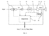
- Figure 1 shows in schematic form the device 10 of the invention which provides an amplified output Vout to a loudspeaker 11.
- a digital input signal is filtered by the filter 12 and fed into a delay line 14 and converted to the analog domain by a digital to analogue converter 16 ("DAC”) and amplified by amplifier 18.
- DAC digital to analogue converter
- the current flowing into the loudspeaker is measured (“Isense”) by a current sensor 20, and is used for computing the loudspeaker diagnostics.
- the audio input to the circuit can be considered to be the pre-filtered signal or the signal V1 at the output of the filter.
- a processing module 22 carries out the calculation of the loudspeaker parameters.
- the clipping level of the amplifier is also used for computing the diagnostics, and this is represented by the line 24.
- the inputs to the diagnostics module 22 are the following:
- Vout which is sent to the loudspeaker
- Vout can be estimated based on V1, the gain and the clipping level of the amplifier 18.
- Vout can thus be derived by multiplying V1 with the amplifier gain, and passing it through a nonlinear model of the amplifier (such as a hard or a soft clipper).
- the derived signal Vout is a prediction of a future value rather than the current Vout value.
- respective up-and down-sampling stages can be added to lower aliasing artifacts (by performing the nonlinear operation at a higher sampling rate, aliasing effects are lowered).
- the electrical impedance function can be estimated.
- the loudspeaker model can then be estimated from the electrical impedance function.
- the voltage-to-displacement transfer function is obtained, and the predicted excursion, Xn, can be computed by applying the transfer function to Vout.
- the actual excursion prediction can be computed, if not, it is proportional to the linear prediction (with an unknown scaling factor).
- the resonance frequency, Fres, and the Q-factor, Qres, of the loudspeaker can also be obtained from the electrical impedance function, for example based on the position of the frequency where the peak of the impedance function is obtained, and the 3 dB bandwidth.
- the voice coil temperature, T can be estimated from the DC-impedance of the electrical impedance.
- a signal, D that is related to the loudspeaker distortion can also be derived.
- This signal can for example be obtained as described in EP11173638 (discussed below and not published at the priority date of this application).
- the filtering operation (filter 12 in Fig. 1 ) is optional. It can be included to remove undesired resonance peaks in the acoustical output of the loudspeaker. Indeed, the transfer function of a loudspeaker (from input signal to acoustical output as a function of frequency) can exhibit one or multiple magnitude peaks due to resonance frequencies of the loudspeaker and/or enclosure.
- the filtering operation may also include a high-pass filter to remove frequencies that are reproduced by the loudspeaker with very low efficiency.
- the filtering operation may include a boost or 'correction' of the lower frequencies to compensate for the high-pass characteristic of the acoustical output of the loudspeaker. Indeed, in a typical loudspeaker, the acoustical output for frequencies below the loudspeaker resonance frequency are lower than for frequencies above resonance.
- the acoustical output has a low-frequency roll-off that follows a second-order high-pass filter characteristic for frequencies below resonance. This can be corrected down to a user-defined lower frequency limit (for example as disclosed in Leach, W., 1990. A generalized active equalizer for closed-box loudspeaker systems. J. Audio Eng. Soc. 38, 142-146 ).
- the 14 delay line is also optional. It can be included to implement a look-ahead mechanism. Indeed, it may be necessary to include a look-ahead mechanism in a protection algorithm to ensure that the protection is performed in time.
- the invention thus provides a device which contains at least an amplifier, a means for sensing the current flowing from the amplifier, and a module to determine loudspeaker diagnostics. These diagnostics can then be provided as outputs from the device.
- the output loudspeaker diagnostics that can be determined include one or several of the following:
- the amplifier can have a variable gain which is controlled in such a way that the expected power consumption does not exceed a certain threshold.
- EP11170997 discloses an alternative way to derive a loudspeaker model. It discloses a time-domain estimation method, where the transfer function between voltage and current (i.e. admittance) are estimated in the time domain and are used to derive a voltage-to-excursion transfer function. This can in turn be used to derive a voltage-to-acoustical-output transfer function.
- the model can be adjusted gradually over time, without abrupt changes. This approach does not require prior knowledge regarding the enclosure (e.g. closed or vented box) and can cope with complex designs of the enclosure.
- a non-parametric model is therefore valid in the general case. It is based on a basic property of a loudspeaker/enclosure that is valid for most loudspeaker/enclosure combinations. Therefore, it remains valid when there are defects caused in the production process, or caused by mechanical damage, which would affect the validity of parametric models.
- An admittance function (which is inverse to an impedance function, so that either can be derived and they are interchangeable by simply operating a reciprocal function) is obtained over time from the voice coil voltage and current signals.
- the force factor of the loudspeaker and the blocked electrical impedance the input-voltage-to-excursion transfer function over time is obtained. This is used to control audio processing for the loudspeaker thereby to implement loudspeaker protection and/or acoustic signal processing.
- Estimation of the force factor requires a signal derived from an additional sensor (e.g., a laser to measure the diaphragm displacement), when the loudspeaker is in a known configuration (e.g., infinite baffle, without an enclosure).
- an additional sensor e.g., a laser to measure the diaphragm displacement
- the blocked impedance will not be perfectly constant, for example it changes with temperature. This is not taken into account in the model described below, but the blocked impedance can be re-estimated in the modelling process.
- Equation (18) shows that the voltage-to-excursion transfer function can be computed as the convolution of an integrator with a linear filter derived from the admittance, y(t), of the loudspeaker.
- h ⁇ ⁇ x k 1 ⁇ ⁇ ⁇ k - R e ⁇ y k * h int k
- ⁇ [k] is the delta function
- the diaphragm displacement can now be obtained by filtering the voltage signal with h vx[ k].
- This filtering operation can be split into two filtering operations, one with: 1 ⁇ ⁇ ⁇ k - R e ⁇ y k and one with h int [k].
- This relationship can be estimated in the time-domain, using the well-known adaptive filtering theory, e.g. a normalised least-mean-square approach (see, e.g., Haykin, 2002 - Adaptive Filter Theory, 4th Edition. Prentice Hall, Upper Saddle River, NJ .).
- adaptive filtering theory e.g. a normalised least-mean-square approach (see, e.g., Haykin, 2002 - Adaptive Filter Theory, 4th Edition. Prentice Hall, Upper Saddle River, NJ .).
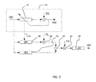
- FIG. 2 A schematic rendition of the adaptive scheme is shown in Figure 2 , although the voltage and current measurements can be taken using the circuit of Figure 1 .
- the dashed rectangle 30 is the part of the system that estimates the admittance function y[k]. It adapts the coefficients of a filter 32 such that the discrepancy, e[k], between the output of the filter and the current, i[k], is minimal, e.g. in the least-squares sense.
- the coefficients of the adaptive filter are optionally smoothed over time, and copied (dashed arrow 34 in Figure 2 ) to the part of the system that is used for computing the diaphragm displacement.
- the filter transfer function comprises the ratio of i[k] to v[k] and thus is a model of the admittance function y[k]. This function y[k] is duplicated in the lower part of the circuit.
- It comprises the copied admittance function 36, a multiplier 38 for multiplying by the blocked resistance Re, and an adder 40 for adding to the impulse function generated by unit 42.
- the admittance function y[k] is multiplied by the blocked electrical impedance Re and subtracted from the delta function ⁇ [k].
- the result is scaled by the inverse of the force factor ⁇ by the multiplier 44 before processing by the integrator transfer function h int[ k] in block 46.
- v[k], i[k] and e[k] are digitized time signals (for example 16-bit discrete values between -1 and 1).
- the blocks shown as ⁇ [k] and y[k] can be implemented as impulse responses (FIR filters) of length N.
- hint[k] is an IIR filter, the transfer function of which is described by Eq. (20), and is characterised by a set of coefficients.
- h ⁇ p s ⁇ 0 ⁇ S d 2 ⁇ ⁇ d ⁇ s 2 ⁇ h ⁇ x s ,
- ⁇ 0 is the density of air
- S d is the effective diaphragm radiating area
- d is the distance between loudspeaker and evaluation point.
- h ⁇ p k ⁇ 0 ⁇ S d 2 ⁇ ⁇ d ⁇ ⁇ ⁇ ⁇ k - R e ⁇ y k * h diff k
- the transfer function (Eq. (23)) can be used for non-parametric linearisation of the acoustic response of the loudspeaker, i.e. to derive a filtering operation that renders the expected acoustical response uniform across frequencies, or to derive a filtering operation that changes the expected acoustical response to a certain desired response.
- the transfer function(s) are computed on the basis of recordings of voltage across and current flowing into the loudspeaker voice coil, or are computed in an on-line fashion while sound is played on the loudspeaker.
- the transfer function(s) are computed in the time domain and the method avoids the need for a parametric model of a loudspeaker.
- a series resistor can be used for current sensing, in the path of the voice coil of the loudspeaker.
- the voltages on each end of the resistor are then monitored by the processor 22, which implements the algorithm.
- the measure of non-linearity is also based on the voice coil voltage and current.
- non-linearity measure is the maximum excursion. However, a more generic measurement of non-linearity can be made. The non-linearity parameter can then be used as the control input for the processing of the audio signal. A feedback control loop can then be formed which avoids the need for the input-voltage-to-excursion transfer function.
- v k i k * z k
- z[k] is the impulse response corresponding to the electrical impedance function of the loudspeaker (the linear transfer function from current to voltage).
- a first possibility uses a fixed electrical impedance, that is determined in an initial estimation phase.
- the impedance function can be determined by playing a noise sequence on the loudspeaker at a low amplitude, such that the diaphragm displacement is very small, and computing the transfer function from current to voltage. Estimation methods are available in the literature.
- the impulse response corresponding to this transfer function is referred to as z 0 [k].
- An example non-linearity measure is the ratio of the (smoothed) signal powers of the measured voltage and e 0 [k].
- a second possibility uses an adaptive electrical impedance, that is estimated in an on-line manner.
- This possibility adapts to changes in the impedance function due to, e.g., loudspeaker aging, and takes into account differences across samples. Furthermore, it does not require an initial estimation stage.
- the circuit of Figure 1 can again implement the non-linearity analysis explained above, with the processor 22 implementing the algorithm to derive the non-linearity or distortion measure.
- the invention derives loudspeaker characteristics and/or diagnostics which can be used to control the audio processing in order to implement loudspeaker protection and/or acoustic signal processing (such as flattening, or frequency selective filtering).
- loudspeaker protection and/or acoustic signal processing such as flattening, or frequency selective filtering.
- Mechanical and thermal protection is particularly interesting for customers that want to maintain control over the audio path, without having to develop methods to obtain the loudspeaker diagnostics.
- the invention can also be used in a loudspeaker maximisation algorithm. It can also be used to linearise the acoustic response of a loudspeaker, to make it uniform across frequencies (to give a flat frequency response) or to make it as close as possible to a desired frequency response, in a non-parametric manner, i.e., without assuming knowledge regarding the enclosure.
- the invention is also able to handle complex designs of the enclosure without requiring a more complex model.
- EP10152597 (published as EP 2 355 542 ) is mentioned above. This discloses a frequency domain analysis which is analogous to the time domain analysis outlined above, and which is disclosed in unpublished EP11170997 .
- the characteristics and/or diagnostics generated by the amplifier can be used by any independent processor.
- This independent processor will then process the digital audio input signal to implement the desired processing before it is supplied to the amplifier circuit of the invention.
- the means for determining a clipping level can comprise a measure derived from the measured battery voltage (when the battery voltage drops, the amplifier clipping level drops also), or a measure derived from the observed distortion in the current sense signal, since the clipping behaviour will also be apparent in the measured current signal.
- the invention does not reside in the specific characteristics and diagnostics that are measured, and indeed any other known loudspeaker parameters than can be obtained from the current and voltage signals and amplifier characteristics can be provided as output.
- the invention involves separation of the diagnostic measurements and the audio signal processing, so that a device is provided which essentially provides only the basic signal amplification and diagnostic functions - the diagnostic information is then used by other circuitry.
Abstract
Description
- This invention relates to a device for determining loudspeaker characteristics and/or diagnostics.
- It is well known that the output of a loudspeaker should be controlled in such a way that it is not simply driven by any input signal. For example, signals should be controlled to prevent loudspeaker failure. Two important causes of loudspeaker failure are mechanical and thermal defects.
- A mechanical defect arises when the loudspeaker diaphragm is displaced beyond a certain limit, which is usually supplied by the manufacturer.
- A thermal defect occurs when there is too much heat dissipation in the loudspeaker. Going beyond the displacement and/or thermal limit either damages the loudspeaker immediately, or can considerably reduce its expected life-time.
- There exist several methods to limit the displacement of the diaphragm of a loudspeaker to prevent such failures, for example by processing the input signal with variable cut-off filters (high-pass or other), the characteristics of which are controlled via a feedforward or feedback control loop. The measured control signal is referred to as the displacement predictor, and this requires modelling of the loudspeaker characteristics so that the displacement can be predicted in response to a given input signal.
- Many applications of electrodynamic loudspeaker modelling, such as loudspeaker protection as mentioned above and also linearisation of the loudspeaker output, contain a module that predicts the diaphragm displacement, also referred to as cone excursion, using a model of a loudspeaker. This model can be linear or non-linear and usually has parameters that allow for a physical interpretation.
- Loudspeaker characteristics are thus used to implement loudspeaker protection mechanisms, to prevent loudspeaker failure. These characteristics can be provided by the manufacturer, following detailed testing. However, they may vary from one device to another. For this reason, each individual loudspeaker is ideally characterised.
- According to the invention, there is provided an apparatus and method as defined in the independent claims.
- In one aspect, the invention provides a loudspeaker drive circuit for deriving characteristics and/or diagnostics of a loudspeaker driven by the drive circuit, comprising:
- an amplifier;
- means for determining a clipping level of the amplifier;
- means for sensing the current flowing into the loudspeaker; and
- a processing module to determine the loudspeaker characteristics and/or diagnostics, based on the input audio signal, the sensed current and the clipping level of the amplifier; and
- means for outputting loudspeaker characteristics and/or diagnostics.
- The device of the invention essentially uses an audio amplifier (with known gain) and a means to measure the current flowing into the loudspeaker load driven by the amplifier, in combination with determination of the clipping level of the amplifier. The known gain and the clipping level together define the amplifier transfer function. The amplifier clipping can vary for example with the battery level.
- A number of loudspeaker diagnostics can be computed and output, such that they can conveniently be used for further processing, for example to implement a loudspeaker protection mechanism. The loudspeaker diagnostics can be mechanical characteristics (for example Fres, Qres) and predicted or measured signals that quantify the behaviour of the loudspeaker.
- The device thus combines an audio amplifier and a processing module to determine a number of loudspeaker diagnostics, which are provided as outputs. This device allows a user to develop audio processing and loudspeaker protection software modules without the need to spend development effort into the characterisation of the loudspeaker.
- In this way, the diagnostic and characterisation of the loudspeaker is built in to the amplification function, but the further signal processing for overload or thermal protection (for example) remain separate. This means that the amplifier stage can be used by a variety of signal processing platforms, giving flexibility to the end user in how to implement the desired signal processing.
- The drive circuit preferably comprises a delay element between the audio input and the amplifier, such that the derived amplifier output voltage is a predicted amplifier output voltage to be supplied to the loudspeaker after the delay of the delay element. This enables the protection which will use the characteristics/diagnostics to be implemented in a predictive (feedforward) manner.
- The processing module can be adapted to derive the amplifier output voltage which is supplied to the loudspeaker based on the audio input provided to the circuit and the known gain and clipping level of the amplifier. This gives the predicted output when a delay element is used.
- The processing module can derive a loudspeaker temperature, for example from the sensed current and the amplifier output voltage supplied to the loudspeaker.
- The processing module can also be adapted to derive an electrical impedance function from the amplifier output voltage and the sensed current. This can be used to obtain various loudspeaker parameters, including a voltage to displacement transfer function for the loudspeaker, from which the loudspeaker excursion can be obtained based on the amplifier output voltage. A measure of loudspeaker distortion can also be obtained based on the electrical impedance function. A resonance frequency for the loudspeaker and a Q-factor can also be obtained for the loudspeaker from the electrical impedance function.
- The loudspeaker amplifier can be used as the drive circuit for using the loudspeaker.
- In another aspect, the invention provides a method of deriving characteristics and/or diagnostics of a loudspeaker, comprising:
- driving the loudspeaker using an amplifier;
- determining a clipping level of the amplifier;
- sensing the current flowing into the loudspeaker;
- determining the loudspeaker characteristics and/or diagnostics, based on the input audio signal, the sensed current and the clipping level of the amplifier; and
- outputting the loudspeaker characteristics and/or diagnostics.
- An example of the invention will now be described in detail with reference to the accompanying drawings, in which:
-
Figure 1 shows a loudspeaker drive circuit of the invention; -
Figure 2 shows one way of deriving a loudspeaker model. - The invention provides a loudspeaker amplifier, wherein various signals relating to the input and output of the amplifier are analysed such that the characteristics and/or diagnostics of a loudspeaker driven by the amplifier can be derived. These are then presented as outputs, so that different circuitry can make use of the information for audio signal processing.
- In this way, information is provided regarding the loudspeaker behaviour that is relevant for audio processing modules, thereby taking away the need for spending significant research effort in the characterisation of the loudspeaker model. Indeed, once the loudspeaker diagnostics, such as those provided by the device of the invention, are available, traditional signal processing modules and control mechanisms can be implemented (dynamic range compression, PID controllers, etc.), without knowledge about how the diagnostics have been obtained.
- The invention enables a loudspeaker model to be formed which is specific to an individual loudspeaker, thereby enabling the prediction of the diaphragm displacement, and enables the voice coil temperature to be determined, for thermal protection.
- A loudspeaker model is typically based on the physical behaviour of the loudspeaker and the enclosure in which it is mounted. The parameters of a model are determined in order to characterise a specific loudspeaker.
- The model parameters can be estimated by minimising the discrepancy between the measured electrical impedance and the impedance predicted by the loudspeaker model (as a function of the parameters). There exist alternatives, such as that described in
EP10152597 EP11170997 - To measure the electrical impedance, the voltage across the loudspeaker coil and the current flowing into the loudspeaker need to be known. From this loudspeaker model, useful transfer functions can be derived, such as the voltage-to-displacement transfer function, which predicts the diaphragm displacement for a given input voltage signal. The diaphragm displacement, or cone excursion, is a measure for how far the cone has moved from its rest position. To obtain the correct voltage-to-displacement transfer function, however, an additional parameter needs to be known, namely the so-called force factor or BI-product.
- In a linear model, the displacement scales inversely linearly with the force factor, and therefore, the excursion can be linearly predicted up to an (unknown) scaling factor without knowledge of the physical BI-product value. The electrical impedance can also be used to determine the resonance frequency of the loudspeaker and its Q-factor. This information can for example be used to generate a digital filter to linearise the acoustical output of the loudspeaker.
- Voice coil temperature estimation is also carried out as part of the characterisation of the loudspeaker.
- Loudspeakers are essentially devices to convert electrical energy into acoustical energy. However, much of the electrical power that is applied to the loudspeaker results in heat dissipation, which increases the temperature of the loudspeaker voice coil. There exist methods for predicting the voice coil temperature based on a number of pre-estimated parameters starting from the electrical signal that is sent to the loudspeaker (Chapman, P., May 1998. Thermal simulation of loudspeakers. In: Proceedings of the 104th AES Convention, Amsterdam. Paper number 4667 and Klippel, W., 2004. Nonlinear modelling of the heat transfer in loudspeakers. J. Audio Eng. Soc. 52, 3-25.). These methods predict the voice coil temperature based on a thermal model of the loudspeaker, and do not measure the temperature or derivatives thereof.
- Other methods derive the temperature from the DC-resistance of the loudspeaker: as the input power is dissipated into heat, the rise in temperature also increases the DC resistance of the voice coil, Re. The temperature of the voice coil, T , can be estimated from the DC resistance, Re, with respect to a reference DC resistance, Re0, at a reference temperature, To (Behler, G., Spätling, U., Arimont, T., February 1995. Measuring the loudspeaker's impedance during operation for the evaluation of the voice coil temperature. In: Proceedings of the 98th AES Convention, Paris. Paper number 4001.) in the following manner.

α 0 and β0 are temperature coefficients that depend on the properties of the voice coil material. Thus, if the DC resistance is known for a certain temperature, these values can be used as references for further voice coil temperature estimation, and it is possible to estimate absolute temperatures. - If such values are not known, a temperature increase with respect to a previously measured (but unknown) temperature can be estimated. These methods measure a signal related to the temperature, rather than generating a model-based prediction.
-
Figure 1 shows in schematic form thedevice 10 of the invention which provides an amplified output Vout to aloudspeaker 11. - A digital input signal is filtered by the
filter 12 and fed into adelay line 14 and converted to the analog domain by a digital to analogue converter 16 ("DAC") and amplified byamplifier 18. The current flowing into the loudspeaker is measured ("Isense") by acurrent sensor 20, and is used for computing the loudspeaker diagnostics. - The audio input to the circuit can be considered to be the pre-filtered signal or the signal V1 at the output of the filter.
- A
processing module 22 carries out the calculation of the loudspeaker parameters. - The clipping level of the amplifier is also used for computing the diagnostics, and this is represented by the
line 24. - The inputs to the
diagnostics module 22 are the following: - Isense: the current flowing into the loudspeaker voice coil;
- Vclip: the clipping level of the
amplifier 18; - V1 the digital audio signal, of which a delayed version is sent to the
DAC 16. - The analog audio signal, Vout, which is sent to the loudspeaker, can be estimated based on V1, the gain and the clipping level of the
amplifier 18. Vout can thus be derived by multiplying V1 with the amplifier gain, and passing it through a nonlinear model of the amplifier (such as a hard or a soft clipper). - By estimating (rather than measuring) Vout, a prediction of the analog output voltage is obtained, and the delay line is used for this purpose. The protection can be implemented and can be performed in real time. Thus, the derived signal Vout is a prediction of a future value rather than the current Vout value.
- Before and after the nonlinear model, respective up-and down-sampling stages can be added to lower aliasing artifacts (by performing the nonlinear operation at a higher sampling rate, aliasing effects are lowered).
- Based on Vout and Isense, the electrical impedance function can be estimated.
- The loudspeaker model can then be estimated from the electrical impedance function.
- From the electrical impedance model, the voltage-to-displacement transfer function is obtained, and the predicted excursion, Xn, can be computed by applying the transfer function to Vout.
- When the BI-product is known, the actual excursion prediction can be computed, if not, it is proportional to the linear prediction (with an unknown scaling factor).
- The resonance frequency, Fres, and the Q-factor, Qres, of the loudspeaker can also be obtained from the electrical impedance function, for example based on the position of the frequency where the peak of the impedance function is obtained, and the 3 dB bandwidth.
- The voice coil temperature, T, can be estimated from the DC-impedance of the electrical impedance.
- From the electrical impedance, a signal, D, that is related to the loudspeaker distortion can also be derived. This signal can for example be obtained as described in
EP11173638 - The filtering operation (filter 12 in
Fig. 1 ) is optional. It can be included to remove undesired resonance peaks in the acoustical output of the loudspeaker. Indeed, the transfer function of a loudspeaker (from input signal to acoustical output as a function of frequency) can exhibit one or multiple magnitude peaks due to resonance frequencies of the loudspeaker and/or enclosure. - Reducing these resonance peaks can linearise the frequency response and create headroom that may be used for boosting the input signal. The filtering operation may also include a high-pass filter to remove frequencies that are reproduced by the loudspeaker with very low efficiency. The filtering operation may include a boost or 'correction' of the lower frequencies to compensate for the high-pass characteristic of the acoustical output of the loudspeaker. Indeed, in a typical loudspeaker, the acoustical output for frequencies below the loudspeaker resonance frequency are lower than for frequencies above resonance.
- For example for a closed-box configuration, the acoustical output has a low-frequency roll-off that follows a second-order high-pass filter characteristic for frequencies below resonance. This can be corrected down to a user-defined lower frequency limit (for example as disclosed in Leach, W., 1990. A generalized active equalizer for closed-box loudspeaker systems. J. Audio Eng. Soc. 38, 142-146).
- The 14 delay line is also optional. It can be included to implement a look-ahead mechanism. Indeed, it may be necessary to include a look-ahead mechanism in a protection algorithm to ensure that the protection is performed in time.
- The invention thus provides a device which contains at least an amplifier, a means for sensing the current flowing from the amplifier, and a module to determine loudspeaker diagnostics. These diagnostics can then be provided as outputs from the device.
- The output loudspeaker diagnostics that can be determined include one or several of the following:
- the measured or estimated input signal to the loudspeaker;
- an estimate of the voice coil temperature;
- linear prediction of the loudspeaker diaphragm displacement (possibly scaled by an unknown scaling factor);
- a signal related to the loudspeaker nonlinearities;
- the resonance frequency and the Q-factor of the loudspeaker.
- The amplifier can have a variable gain which is controlled in such a way that the expected power consumption does not exceed a certain threshold.
- As mentioned above,
EP11170997 - A non-parametric model is therefore valid in the general case. It is based on a basic property of a loudspeaker/enclosure that is valid for most loudspeaker/enclosure combinations. Therefore, it remains valid when there are defects caused in the production process, or caused by mechanical damage, which would affect the validity of parametric models.
- An admittance function (which is inverse to an impedance function, so that either can be derived and they are interchangeable by simply operating a reciprocal function) is obtained over time from the voice coil voltage and current signals. In combination with a delta function, the force factor of the loudspeaker and the blocked electrical impedance, the input-voltage-to-excursion transfer function over time is obtained. This is used to control audio processing for the loudspeaker thereby to implement loudspeaker protection and/or acoustic signal processing.
- In order to explain the approach of
EP11170997 - An expression for the voltage-to-excursion transfer function is derived as a function of the admittance, Y(s), which is the inverse of the electrical impedance transfer function, Z(s).
- The voltage equation for an electrodynamic loudspeaker, which relates the loudspeaker voice coil voltage, v(t), to the voice coil current, i(t) and the diaphragm velocity ẋ(t) is the following:

where Re and Le are the DC resistance and the inductance of the voice coil when the voice coil is mechanically blocked, φ is the force factor or BI-product (assumed to be constant), and ẋ(t) is the velocity of the diaphragm. - The Laplace transform yields:

where Ze(s) is the blocked electrical impedance of the voice coil. The force factor, φ, represents the ratio between the Lorentz force, which is exerted on the cone, and the input current:
- Estimation of the force factor requires a signal derived from an additional sensor (e.g., a laser to measure the diaphragm displacement), when the loudspeaker is in a known configuration (e.g., infinite baffle, without an enclosure).
- Known techniques for estimating or measuring these parameters will be well known to those skilled in the art.
- The blocked impedance will not be perfectly constant, for example it changes with temperature. This is not taken into account in the model described below, but the blocked impedance can be re-estimated in the modelling process. There are many methods for estimating the blocked electrical impedance, and its estimation is not part of the proposed invention. For example, reference is made to Leach, W., 2002: "Loudspeaker voice-coil inductance losses: Circuit models, parameter estimation, and effect on frequency response" J. Audio Eng. Soc. 50 (6), 442-450, and Vanderkooy, J., 1989: "A model of loudspeaker driver impedance incorporating eddy currents in the pole structure" J. Audio Eng. Soc. 37, 119-128.
- The mechanical impedance is defined as the ratio between force and velocity:


- Rearranging the voltage equation Eq. (2), yields:


from which an expression for the mechanical impedance is derived:
- Starting from the voltage equation (Eq. (2)), an expression for the voltage-to-excursion transfer function can be derived:


from which the Laplace-domain voltage-to-displacement transfer function hvx(s) is derived:
- The Laplace domain transfer function can be rewritten:


- If it is now assumed that the blocked electrical impedance, Ze(s), is purely resistive (as is often done for micro-speakers), i.e. Ze(s) = Re, the voltage-to-excursion transfer function can be written as:

where Y(s) = Z(s)-1 is the admittance of the loudspeaker. The time-domain equivalent of this transfer function is the following:
where δ(t) is the Dirac pulse, and L-1 denotes the inverse Laplace transform. - Equation (18) shows that the voltage-to-excursion transfer function can be computed as the convolution of an integrator with a linear filter derived from the admittance, y(t), of the loudspeaker.
- In the discrete-time case, it can be easily derived that:

where δ[k] is the delta function, and hint[k] is a (leaky) integrator, e.g. described by:
with γleak the integrator leakage factor and fs is the sampling rate. - The diaphragm displacement can now be obtained by filtering the voltage signal with hvx[k]. This filtering operation can be split into two filtering operations, one with:

and one with hint[k]. - In the voltage-to-excursion transfer function (Eq. (19)), it is assumed that φ and Re are known. The admittance, y[k] can be estimated as the linear transfer function between the voltage and the current signal, since:

- This relationship can be estimated in the time-domain, using the well-known adaptive filtering theory, e.g. a normalised least-mean-square approach (see, e.g., Haykin, 2002 - Adaptive Filter Theory, 4th Edition. Prentice Hall, Upper Saddle River, NJ.).
- A schematic rendition of the adaptive scheme is shown in
Figure 2 , although the voltage and current measurements can be taken using the circuit ofFigure 1 . - The dashed
rectangle 30 is the part of the system that estimates the admittance function y[k]. It adapts the coefficients of afilter 32 such that the discrepancy, e[k], between the output of the filter and the current, i[k], is minimal, e.g. in the least-squares sense. - The coefficients of the adaptive filter are optionally smoothed over time, and copied (dashed arrow 34 in
Figure 2 ) to the part of the system that is used for computing the diaphragm displacement. The filter transfer function comprises the ratio of i[k] to v[k] and thus is a model of the admittance function y[k]. This function y[k] is duplicated in the lower part of the circuit. - The lower part is a possible implementation of Eq. (19), and yields the diaphragm displacement, x[k].
- It comprises the copied
admittance function 36, amultiplier 38 for multiplying by the blocked resistance Re, and anadder 40 for adding to the impulse function generated byunit 42. - In this way, the admittance function y[k] is multiplied by the blocked electrical impedance Re and subtracted from the delta function δ[k]. The result is scaled by the inverse of the force factor φby the
multiplier 44 before processing by the integrator transfer function hint[k] inblock 46. - v[k], i[k] and e[k] are digitized time signals (for example 16-bit discrete values between -1 and 1). The blocks shown as δ[k] and y[k] can be implemented as impulse responses (FIR filters) of length N.
- The block shown as hint[k] is an IIR filter, the transfer function of which is described by Eq. (20), and is characterised by a set of coefficients.
- The corresponding acoustical output transfer function can be obtained as the second derivative of hvx[k], scaled by a constant factor. In the Laplace domain, this yields:

- Where ρ0 is the density of air, Sd is the effective diaphragm radiating area, and d is the distance between loudspeaker and evaluation point. This transfer function assumes a half-plane radiation and neglects the phase lag caused by wave propagation (thus, the phase information is incorrect).
- From Eq. (19), the time-domain voltage-to-acoustical output transfer function can be obtained:


- The transfer function (Eq. (23)) can be used for non-parametric linearisation of the acoustic response of the loudspeaker, i.e. to derive a filtering operation that renders the expected acoustical response uniform across frequencies, or to derive a filtering operation that changes the expected acoustical response to a certain desired response.
- There is thus a method to predict the diaphragm displacement for a given input voltage. The transfer function(s) are computed on the basis of recordings of voltage across and current flowing into the loudspeaker voice coil, or are computed in an on-line fashion while sound is played on the loudspeaker. The transfer function(s) are computed in the time domain and the method avoids the need for a parametric model of a loudspeaker.
- The approach above can be implemented by the circuit of
Figure 1 . A series resistor can be used for current sensing, in the path of the voice coil of the loudspeaker. The voltages on each end of the resistor are then monitored by theprocessor 22, which implements the algorithm. - Reference is also made above to
EP11173638 - The measure of non-linearity is also based on the voice coil voltage and current.
- One known non-linearity measure is the maximum excursion. However, a more generic measurement of non-linearity can be made. The non-linearity parameter can then be used as the control input for the processing of the audio signal. A feedback control loop can then be formed which avoids the need for the input-voltage-to-excursion transfer function.
- There are several possibilities to compute the measure of non-linearity based on the electrical impedance of the loudspeaker:

where * denotes the convolution operator, and z[k] is the impulse response corresponding to the electrical impedance function of the loudspeaker (the linear transfer function from current to voltage). - A first possibility uses a fixed electrical impedance, that is determined in an initial estimation phase.
- The impedance function can be determined by playing a noise sequence on the loudspeaker at a low amplitude, such that the diaphragm displacement is very small, and computing the transfer function from current to voltage. Estimation methods are available in the literature.
- The impulse response corresponding to this transfer function is referred to as z0[k]. The measure of non-linearity is derived from the discrepancy between the measured voltage ṽ[k] and that expected from the measured current ĩ[k] given the fixed electrical impedance:

- An example non-linearity measure is the ratio of the (smoothed) signal powers of the measured voltage and e0[k].
- A second possibility uses an adaptive electrical impedance, that is estimated in an on-line manner. Indeed, the impedance can be estimated using an adaptive filter that minimises the following error signal in terms of the impulse response z1[k]:

- This possibility adapts to changes in the impedance function due to, e.g., loudspeaker aging, and takes into account differences across samples. Furthermore, it does not require an initial estimation stage.
- The circuit of
Figure 1 can again implement the non-linearity analysis explained above, with theprocessor 22 implementing the algorithm to derive the non-linearity or distortion measure. - The invention derives loudspeaker characteristics and/or diagnostics which can be used to control the audio processing in order to implement loudspeaker protection and/or acoustic signal processing (such as flattening, or frequency selective filtering). Mechanical and thermal protection is particularly interesting for customers that want to maintain control over the audio path, without having to develop methods to obtain the loudspeaker diagnostics. The invention can also be used in a loudspeaker maximisation algorithm. It can also be used to linearise the acoustic response of a loudspeaker, to make it uniform across frequencies (to give a flat frequency response) or to make it as close as possible to a desired frequency response, in a non-parametric manner, i.e., without assuming knowledge regarding the enclosure. The invention is also able to handle complex designs of the enclosure without requiring a more complex model.
-
EP10152597 EP 2 355 542 ) is mentioned above. This discloses a frequency domain analysis which is analogous to the time domain analysis outlined above, and which is disclosed in unpublishedEP11170997 - The characteristics and/or diagnostics generated by the amplifier can be used by any independent processor. This independent processor will then process the digital audio input signal to implement the desired processing before it is supplied to the amplifier circuit of the invention.
- The means for determining a clipping level can comprise a measure derived from the measured battery voltage (when the battery voltage drops, the amplifier clipping level drops also), or a measure derived from the observed distortion in the current sense signal, since the clipping behaviour will also be apparent in the measured current signal.
- The invention does not reside in the specific characteristics and diagnostics that are measured, and indeed any other known loudspeaker parameters than can be obtained from the current and voltage signals and amplifier characteristics can be provided as output. The invention involves separation of the diagnostic measurements and the audio signal processing, so that a device is provided which essentially provides only the basic signal amplification and diagnostic functions - the diagnostic information is then used by other circuitry.
- Other variations to the disclosed embodiments can be understood and effected by those skilled in the art in practicing the claimed invention, from a study of the drawings, the disclosure, and the appended claims. In the claims, the word "comprising" does not exclude other elements or steps, and the indefinite article "a" or "an" does not exclude a plurality. The mere fact that certain measures are recited in mutually different dependent claims does not indicate that a combination of these measured cannot be used to advantage. Any reference signs in the claims should not be construed as limiting the scope.
Claims (15)
- A loudspeaker drive circuit for deriving characteristics and/or diagnostics of a loudspeaker driven by the drive circuit, comprising:an amplifier (18);means for determining a clipping level of the amplifier;a means (20) for sensing the current flowing into the loudspeaker;a processing module (22) to determine the loudspeaker characteristics and/or diagnostics, based on the input audio signal (V1), the sensed current (Isense) and the clipping level of the amplifier; andmeans for outputting the characteristics and/or diagnostics.
- A circuit as claimed in claim 1, wherein the processing module (22) is adapted to derive a loudspeaker temperature.
- A circuit as claimed in claim 1, wherein the processing module (22) is adapted to derive the amplifier output voltage (Vout) which is supplied to the loudspeaker (11) based on the audio input (V1) provided to the circuit and the known gain and clipping level of the amplifier (18).
- A circuit as claimed in claim 3, wherein the drive circuit comprises a delay element (14) between the audio input (V1) and the amplifier, such that the derived amplifier output voltage is a predicted amplifier output voltage to be supplied to the loudspeaker after the delay of the delay element.
- A circuit as claimed in claim 3 or 4, wherein the processing module (22) is adapted to derive an electrical impedance function from the amplifier output voltage and the sensed current.
- A circuit as claimed in claim 5, wherein the processing module (22) is adapted to derive a voltage to displacement transfer function for the loudspeaker, and thereby derive the loudspeaker excursion based on the amplifier output voltage.
- A circuit as claimed in claim 5 or 6, wherein the processing module (22) is adapted to derive a measure of loudspeaker distortion based on the electrical impedance function.
- A circuit as claimed in any one of claims 5 to 7, wherein the processing module (22) is adapted to derive a resonance frequency and /or a Q-factor for the loudspeaker from the electrical impedance function.
- A method of deriving characteristics and/or diagnostics of a loudspeaker, comprising:driving the loudspeaker (11) using an amplifier (18);determining a clipping level of the amplifier;sensing the current (Isense) flowing into the loudspeaker (11);determining the loudspeaker characteristics and/or diagnostics, based on the input audio signal (V1), the sensed current (Isense) and the clipping level of the amplifier; andoutputting the loudspeaker characteristics and/or diagnostics.
- A method as claimed in claim 9, comprising deriving the amplifier output voltage which is supplied to the loudspeaker (11) based on the audio input provided to the circuit and the known gain and clipping level of the amplifier.
- A method as claimed in claim 10, comprising providing a delay (14) between the audio input and the amplifier, such that the derived amplifier output voltage is a predicted amplifier output voltage to be supplied to the loudspeaker after the delay of the delay element.
- A method as claimed in claim 10 or 11, comprising deriving a loudspeaker temperature.
- A method as claimed in claim 10, 11 or 12, comprising deriving an electrical impedance function from the amplifier output voltage and the sensed current.
- A method as claimed in claim 13, comprising deriving a voltage to displacement transfer function for the loudspeaker, and thereby deriving the loudspeaker excursion based on the amplifier output voltage.
- A method as claimed in claim 13 or 14, comprising, based on the electrical impedance function, deriving:a measure of loudspeaker distortion; and/ora resonance frequency for the loudspeaker; and/ora Q-factor for the loudspeaker.
Priority Applications (3)
| Application Number | Priority Date | Filing Date | Title |
|---|---|---|---|
| EP12160401.1A EP2642769B1 (en) | 2012-03-20 | 2012-03-20 | A loudspeaker drive circuit for determining loudspeaker characteristics and/or diagnostics |
| US13/762,811 US20130251164A1 (en) | 2012-03-20 | 2013-02-08 | Loudspeaker drive circuit for determining loudspeaker characteristics and/or diagnostics |
| CN201310088169.2A CN103327437B (en) | 2012-03-20 | 2013-03-19 | A loudspeaker drive circuit for determining loudspeaker characteristics and/or diagnostics |
Applications Claiming Priority (1)
| Application Number | Priority Date | Filing Date | Title |
|---|---|---|---|
| EP12160401.1A EP2642769B1 (en) | 2012-03-20 | 2012-03-20 | A loudspeaker drive circuit for determining loudspeaker characteristics and/or diagnostics |
Publications (2)
| Publication Number | Publication Date |
|---|---|
| EP2642769A1 true EP2642769A1 (en) | 2013-09-25 |
| EP2642769B1 EP2642769B1 (en) | 2017-12-13 |
Family
ID=45976092
Family Applications (1)
| Application Number | Title | Priority Date | Filing Date |
|---|---|---|---|
| EP12160401.1A Active EP2642769B1 (en) | 2012-03-20 | 2012-03-20 | A loudspeaker drive circuit for determining loudspeaker characteristics and/or diagnostics |
Country Status (3)
| Country | Link |
|---|---|
| US (1) | US20130251164A1 (en) |
| EP (1) | EP2642769B1 (en) |
| CN (1) | CN103327437B (en) |
Cited By (14)
| Publication number | Priority date | Publication date | Assignee | Title |
|---|---|---|---|---|
| EP2988528A1 (en) * | 2014-08-18 | 2016-02-24 | Nxp B.V. | Voice coil motor and loudspeaker controller |
| JP2018033019A (en) * | 2016-08-25 | 2018-03-01 | オンキヨー株式会社 | Amplifier |
| FR3056064A1 (en) * | 2016-09-14 | 2018-03-16 | Jeremy Clouzeau | PRE-ANALYSIS CORRECTION SYSTEM FOR ELECTRODYNAMIC TRANSDUCERS |
| EP3342179A4 (en) * | 2015-12-28 | 2018-08-22 | Samsung Electronics Co., Ltd. | Control of electrodynamic speaker driver using a low-order non-linear model |
| EP3503582A1 (en) * | 2017-12-21 | 2019-06-26 | Harman International Industries, Incorporated | Constrained nonlinear parameter estimation for robust nonlinear loudspeaker modeling for the purpose of smart limiting |
| US10349195B1 (en) | 2017-12-21 | 2019-07-09 | Harman International Industries, Incorporated | Constrained nonlinear parameter estimation for robust nonlinear loudspeaker modeling for the purpose of smart limiting |
| US10462565B2 (en) | 2017-01-04 | 2019-10-29 | Samsung Electronics Co., Ltd. | Displacement limiter for loudspeaker mechanical protection |
| US10506347B2 (en) | 2018-01-17 | 2019-12-10 | Samsung Electronics Co., Ltd. | Nonlinear control of vented box or passive radiator loudspeaker systems |
| US10536774B2 (en) | 2017-12-21 | 2020-01-14 | Harman International Industries, Incorporated | Constrained nonlinear parameter estimation for robust nonlinear loudspeaker modeling for the purpose of smart limiting |
| US10542361B1 (en) | 2018-08-07 | 2020-01-21 | Samsung Electronics Co., Ltd. | Nonlinear control of loudspeaker systems with current source amplifier |
| US10797666B2 (en) | 2018-09-06 | 2020-10-06 | Samsung Electronics Co., Ltd. | Port velocity limiter for vented box loudspeakers |
| US11012773B2 (en) | 2018-09-04 | 2021-05-18 | Samsung Electronics Co., Ltd. | Waveguide for smooth off-axis frequency response |
| US11356773B2 (en) | 2020-10-30 | 2022-06-07 | Samsung Electronics, Co., Ltd. | Nonlinear control of a loudspeaker with a neural network |
| EP4084503A1 (en) | 2021-04-28 | 2022-11-02 | Nxp B.V. | Audio playback system fault detection method and apparatus |
Families Citing this family (29)
| Publication number | Priority date | Publication date | Assignee | Title |
|---|---|---|---|---|
| US9161126B2 (en) | 2013-03-08 | 2015-10-13 | Cirrus Logic, Inc. | Systems and methods for protecting a speaker |
| US9980068B2 (en) | 2013-11-06 | 2018-05-22 | Analog Devices Global | Method of estimating diaphragm excursion of a loudspeaker |
| EP2890160B1 (en) * | 2013-12-24 | 2019-08-14 | Nxp B.V. | Loudspeaker controller |
| KR101855725B1 (en) | 2014-01-13 | 2018-06-20 | 삼성전자주식회사 | Audio Outputting Control Method and Electronic Device supporting the same |
| US9531433B2 (en) * | 2014-02-07 | 2016-12-27 | Analog Devices Global | Echo cancellation methodology and assembly for electroacoustic communication apparatuses |
| US9959716B2 (en) | 2014-02-13 | 2018-05-01 | Nxp B.V. | Multi-tone haptic pattern generator |
| US9357302B2 (en) * | 2014-02-18 | 2016-05-31 | Maxim Integrated Products, Inc. | System and method for extracting parameters of a speaker without using stimulus |
| CN103929692B (en) * | 2014-03-24 | 2020-03-24 | 联想(北京)有限公司 | Audio information processing method and electronic equipment |
| EP3010251B1 (en) * | 2014-10-15 | 2019-11-13 | Nxp B.V. | Audio system |
| DE102015002009A1 (en) * | 2015-02-20 | 2016-08-25 | Dialog Semiconductor (Uk) Limited | Optimized speaker operation |
| CN106033676B (en) * | 2015-03-13 | 2018-12-11 | 北京智谷睿拓技术服务有限公司 | Audio play control method and device, electronic equipment |
| CN105050019B (en) * | 2015-06-01 | 2018-03-23 | 歌尔股份有限公司 | The method and system of electro-acoustic conversion device amplitude and temperature parameter are verified simultaneously |
| WO2017042098A1 (en) * | 2015-09-10 | 2017-03-16 | Yayuma Audio Sp. Z.O.O. | A method of an audio signal correction |
| CN106612479A (en) * | 2015-10-23 | 2017-05-03 | 钰太芯微电子科技(上海)有限公司 | Loudspeaker based protective circuit |
| CN106817655B (en) * | 2015-12-01 | 2019-11-12 | 展讯通信(上海)有限公司 | Speaker control method and device |
| TWI584274B (en) * | 2016-02-02 | 2017-05-21 | 美律實業股份有限公司 | Audio signal processing method for out-of-phase attenuation of shared enclosure volume loudspeaker systems and apparatus using the same |
| CN110536214A (en) * | 2016-04-11 | 2019-12-03 | 展讯通信(上海)有限公司 | Speaker control method and device |
| CN106341763B (en) * | 2016-11-17 | 2019-07-30 | 矽力杰半导体技术(杭州)有限公司 | Speaker driving apparatus and loudspeaker driving method |
| US10153744B1 (en) * | 2017-08-02 | 2018-12-11 | 2236008 Ontario Inc. | Automatically tuning an audio compressor to prevent distortion |
| US10701485B2 (en) * | 2018-03-08 | 2020-06-30 | Samsung Electronics Co., Ltd. | Energy limiter for loudspeaker protection |
| CN112119643B (en) | 2018-05-18 | 2022-04-22 | 杜比实验室特许公司 | Apparatus, system, and method for offset protection of loudspeakers |
| WO2019233416A1 (en) * | 2018-06-05 | 2019-12-12 | Dong Yaobin | Electrostatic loudspeaker, moving-coil loudspeaker, and apparatus for processing audio signal |
| CN109218952B (en) * | 2018-08-08 | 2020-12-22 | 厦门傅里叶电子有限公司 | Loudspeaker temperature testing system and method based on phase change measurement |
| WO2020146728A1 (en) * | 2019-01-10 | 2020-07-16 | Parts Express International, Inc. | Measuring loudspeaker nonlinearity and asymmetry |
| TWI760707B (en) * | 2020-03-06 | 2022-04-11 | 瑞昱半導體股份有限公司 | Method for calculating displacement of diaphragm of speaker, speaker protection device and computer readable storage medium |
| CN113965851B (en) * | 2020-07-02 | 2024-02-09 | 上海艾为电子技术股份有限公司 | Loudspeaker diaphragm displacement control circuit and control method and electronic equipment |
| CN113965850B (en) * | 2020-07-02 | 2024-01-26 | 上海艾为电子技术股份有限公司 | Loudspeaker diaphragm displacement control circuit and control method and electronic equipment |
| JP2022111608A (en) * | 2021-01-20 | 2022-08-01 | 本田技研工業株式会社 | Active noise controller and vehicle |
| CN113465724A (en) * | 2021-06-22 | 2021-10-01 | 西安艾科特声学科技有限公司 | Secondary sound source with fault detection function for active noise reduction equipment and fault detection method |
Citations (4)
| Publication number | Priority date | Publication date | Assignee | Title |
|---|---|---|---|---|
| EP1887830A2 (en) * | 2006-08-11 | 2008-02-13 | Flying Mole Corporation | Protection circuit and load current detection circuit |
| EP2237569A1 (en) * | 2009-03-31 | 2010-10-06 | Harman International Industries, Incorporated | Motional feedback system |
| EP2355542A1 (en) | 2010-02-04 | 2011-08-10 | Nxp B.V. | Control of a loudspeaker output |
| EP2369852A1 (en) * | 2010-03-17 | 2011-09-28 | Harman International Industries, Incorporated | Audio power management system |
Family Cites Families (10)
| Publication number | Priority date | Publication date | Assignee | Title |
|---|---|---|---|---|
| US5471651A (en) * | 1991-03-20 | 1995-11-28 | British Broadcasting Corporation | Method and system for compressing the dynamic range of audio signals |
| DE4336609A1 (en) * | 1993-10-27 | 1995-05-04 | Klippel Wolfgang | Predictive protective circuit for electroacoustic sound transmitters |
| CN1185908C (en) * | 1999-07-02 | 2005-01-19 | 皇家菲利浦电子有限公司 | Loudspeaker protection system having frequency band selective audio power control |
| US6388524B1 (en) * | 2001-05-04 | 2002-05-14 | Motorola, Inc. | Hysteretic control of audio gain in response to battery conditions |
| US20050031140A1 (en) * | 2003-08-07 | 2005-02-10 | Tymphany Corporation | Position detection of an actuator using a capacitance measurement |
| JP2005072983A (en) * | 2003-08-25 | 2005-03-17 | Matsushita Electric Ind Co Ltd | Voice signal amplifier and acoustic device |
| US20050069153A1 (en) * | 2003-09-26 | 2005-03-31 | Hall David S. | Adjustable speaker systems and methods |
| US7106865B2 (en) * | 2004-12-15 | 2006-09-12 | Motorola, Inc. | Speaker diagnostics based upon driving-point impedance |
| US7940198B1 (en) * | 2008-04-30 | 2011-05-10 | V Corp Technologies, Inc. | Amplifier linearizer |
| US8319507B2 (en) * | 2010-02-08 | 2012-11-27 | Nxp B.V. | System and method for sensing an amplifier load current |
-
2012
- 2012-03-20 EP EP12160401.1A patent/EP2642769B1/en active Active
-
2013
- 2013-02-08 US US13/762,811 patent/US20130251164A1/en not_active Abandoned
- 2013-03-19 CN CN201310088169.2A patent/CN103327437B/en active Active
Patent Citations (4)
| Publication number | Priority date | Publication date | Assignee | Title |
|---|---|---|---|---|
| EP1887830A2 (en) * | 2006-08-11 | 2008-02-13 | Flying Mole Corporation | Protection circuit and load current detection circuit |
| EP2237569A1 (en) * | 2009-03-31 | 2010-10-06 | Harman International Industries, Incorporated | Motional feedback system |
| EP2355542A1 (en) | 2010-02-04 | 2011-08-10 | Nxp B.V. | Control of a loudspeaker output |
| EP2369852A1 (en) * | 2010-03-17 | 2011-09-28 | Harman International Industries, Incorporated | Audio power management system |
Non-Patent Citations (7)
| Title |
|---|
| BEHLER, G.; SP''ATLING, U.; ARIMONT, T.: "Measuring the loudspeaker's impedance during operation for the evaluation of the voice coil temperature", PROCEEDINGS OF THE 98TH AES CONVENTION, February 1995 (1995-02-01) |
| CHAPMAN, P.: "Thermal simulation of loudspeakers", PROCEEDINGS OF THE 104TH AES CONVENTION, May 1998 (1998-05-01) |
| HAYKIN: "Adaptive Filter Theory, 4th Edition", 2002, PRENTICE HALL |
| KLIPPEL, W.: "Nonlinear modelling of the heat transfer in loudspeakers", J. AUDIO ENG. SOC., vol. 52, 2004, pages 3 - 25, XP040507072 |
| LEACH, W.: "A generalized active equalizer for closed-box loudspeaker systems", J. AUDIO ENG. SOC., vol. 38, 1990, pages 142 - 146, XP000143230 |
| LEACH, W.: "Loudspeaker voice-coil inductance losses: Circuit models, parameter estimation, and effect on frequency response", J. AUDIO ENG. SOC., vol. 50, no. 6, 2002, pages 442 - 450, XP001244881 |
| VANDERKOOY, J.: "A model of loudspeaker driver impedance incorporating eddy currents in the pole structure", J. AUDIO ENG. SOC., vol. 37, 1989, pages 119 - 128, XP000007165 |
Cited By (20)
| Publication number | Priority date | Publication date | Assignee | Title |
|---|---|---|---|---|
| EP2988528A1 (en) * | 2014-08-18 | 2016-02-24 | Nxp B.V. | Voice coil motor and loudspeaker controller |
| US9913041B2 (en) | 2014-08-18 | 2018-03-06 | Nxp B.V. | Voice coil motor and loudspeaker controller |
| US10547942B2 (en) | 2015-12-28 | 2020-01-28 | Samsung Electronics Co., Ltd. | Control of electrodynamic speaker driver using a low-order non-linear model |
| CN108476356A (en) * | 2015-12-28 | 2018-08-31 | 三星电子株式会社 | Dynamic loudspeaker driver is controlled using lower order nonlinear model |
| EP3342179A4 (en) * | 2015-12-28 | 2018-08-22 | Samsung Electronics Co., Ltd. | Control of electrodynamic speaker driver using a low-order non-linear model |
| US10008988B2 (en) | 2016-08-25 | 2018-06-26 | Onkyo Corporation | Amplifier |
| JP2018033019A (en) * | 2016-08-25 | 2018-03-01 | オンキヨー株式会社 | Amplifier |
| EP3297158A3 (en) * | 2016-08-25 | 2018-05-02 | Onkyo Corporation | Amplifier |
| FR3056064A1 (en) * | 2016-09-14 | 2018-03-16 | Jeremy Clouzeau | PRE-ANALYSIS CORRECTION SYSTEM FOR ELECTRODYNAMIC TRANSDUCERS |
| US10462565B2 (en) | 2017-01-04 | 2019-10-29 | Samsung Electronics Co., Ltd. | Displacement limiter for loudspeaker mechanical protection |
| US10349195B1 (en) | 2017-12-21 | 2019-07-09 | Harman International Industries, Incorporated | Constrained nonlinear parameter estimation for robust nonlinear loudspeaker modeling for the purpose of smart limiting |
| US10381994B2 (en) | 2017-12-21 | 2019-08-13 | Harman International Industries, Incorporated | Constrained nonlinear parameter estimation for robust nonlinear loudspeaker modeling for the purpose of smart limiting |
| US10536774B2 (en) | 2017-12-21 | 2020-01-14 | Harman International Industries, Incorporated | Constrained nonlinear parameter estimation for robust nonlinear loudspeaker modeling for the purpose of smart limiting |
| EP3503582A1 (en) * | 2017-12-21 | 2019-06-26 | Harman International Industries, Incorporated | Constrained nonlinear parameter estimation for robust nonlinear loudspeaker modeling for the purpose of smart limiting |
| US10506347B2 (en) | 2018-01-17 | 2019-12-10 | Samsung Electronics Co., Ltd. | Nonlinear control of vented box or passive radiator loudspeaker systems |
| US10542361B1 (en) | 2018-08-07 | 2020-01-21 | Samsung Electronics Co., Ltd. | Nonlinear control of loudspeaker systems with current source amplifier |
| US11012773B2 (en) | 2018-09-04 | 2021-05-18 | Samsung Electronics Co., Ltd. | Waveguide for smooth off-axis frequency response |
| US10797666B2 (en) | 2018-09-06 | 2020-10-06 | Samsung Electronics Co., Ltd. | Port velocity limiter for vented box loudspeakers |
| US11356773B2 (en) | 2020-10-30 | 2022-06-07 | Samsung Electronics, Co., Ltd. | Nonlinear control of a loudspeaker with a neural network |
| EP4084503A1 (en) | 2021-04-28 | 2022-11-02 | Nxp B.V. | Audio playback system fault detection method and apparatus |
Also Published As
| Publication number | Publication date |
|---|---|
| US20130251164A1 (en) | 2013-09-26 |
| CN103327437A (en) | 2013-09-25 |
| EP2642769B1 (en) | 2017-12-13 |
| CN103327437B (en) | 2017-04-26 |
Similar Documents
| Publication | Publication Date | Title |
|---|---|---|
| EP2642769B1 (en) | A loudspeaker drive circuit for determining loudspeaker characteristics and/or diagnostics | |
| US9332347B2 (en) | Control of a loudspeaker output | |
| US8798281B2 (en) | Control of a loudspeaker output | |
| US9232311B2 (en) | Method for processing an audio signal with modeling of the overall response of the electrodynamic loudspeaker | |
| US9578416B2 (en) | Control of a loudspeaker output | |
| US9414161B2 (en) | Method, system and apparatus for loudspeaker excursion domain processing | |
| US20150036831A1 (en) | Arrangement and method for converting an input signal into an output signal and for generating a predefined transfer behavior between said input signal and said output signal | |
| US9414160B2 (en) | Method, system and apparatus for loudspeaker excursion domain processing | |
| EP3503583B1 (en) | Constrained nonlinear parameter estimation for robust nonlinear loudspeaker modeling for the purpose of smart limiting | |
| KR20150068995A (en) | Method and arrangement for controlling an electro-acoustical transducer | |
| CN110012395B (en) | System and method for speaker thermal behavior modeling | |
| KR20200127875A (en) | System and method for compensating for non-linear behavior for an acoustic transducer based on magnetic flux | |
| Klippel | Adaptive stabilization of electro-dynamical transducers | |
| KR20200127871A (en) | System and method for compensating for non-linear behavior for an acoustic transducer | |
| CN109951787B (en) | Loudspeaker parameter prediction system | |
| Klippel | Active compensation of transducer nonlinearities | |
| Jakobsson et al. | Modelling and compensation of nonlinear loudspeaker | |
| CN111294718B (en) | Information processing device and method | |
| EP4274256A1 (en) | Measurement-based loudspeaker excursion limiting | |
| CN117015979A (en) | Method for adjusting a loudspeaker, loudspeaker and electronic device |
Legal Events
| Date | Code | Title | Description |
|---|---|---|---|
| PUAI | Public reference made under article 153(3) epc to a published international application that has entered the european phase |
Free format text: ORIGINAL CODE: 0009012 |
|
| AK | Designated contracting states |
Kind code of ref document: A1 Designated state(s): AL AT BE BG CH CY CZ DE DK EE ES FI FR GB GR HR HU IE IS IT LI LT LU LV MC MK MT NL NO PL PT RO RS SE SI SK SM TR |
|
| AX | Request for extension of the european patent |
Extension state: BA ME |
|
| 17P | Request for examination filed |
Effective date: 20131031 |
|
| 17Q | First examination report despatched |
Effective date: 20140121 |
|
| RBV | Designated contracting states (corrected) |
Designated state(s): AL AT BE BG CH CY CZ DE DK EE ES FI FR GB GR HR HU IE IS IT LI LT LU LV MC MK MT NL NO PL PT RO RS SE SI SK SM TR |
|
| RIC1 | Information provided on ipc code assigned before grant |
Ipc: H04R 29/00 20060101ALI20170517BHEP Ipc: H04R 3/04 20060101ALI20170517BHEP Ipc: H04R 3/00 20060101AFI20170517BHEP |
|
| GRAP | Despatch of communication of intention to grant a patent |
Free format text: ORIGINAL CODE: EPIDOSNIGR1 |
|
| INTG | Intention to grant announced |
Effective date: 20170629 |
|
| GRAS | Grant fee paid |
Free format text: ORIGINAL CODE: EPIDOSNIGR3 |
|
| GRAA | (expected) grant |
Free format text: ORIGINAL CODE: 0009210 |
|
| AK | Designated contracting states |
Kind code of ref document: B1 Designated state(s): AL AT BE BG CH CY CZ DE DK EE ES FI FR GB GR HR HU IE IS IT LI LT LU LV MC MK MT NL NO PL PT RO RS SE SI SK SM TR |
|
| REG | Reference to a national code |
Ref country code: GB Ref legal event code: FG4D |
|
| REG | Reference to a national code |
Ref country code: AT Ref legal event code: REF Ref document number: 955393 Country of ref document: AT Kind code of ref document: T Effective date: 20171215 Ref country code: CH Ref legal event code: EP |
|
| REG | Reference to a national code |
Ref country code: IE Ref legal event code: FG4D |
|
| REG | Reference to a national code |
Ref country code: DE Ref legal event code: R096 Ref document number: 602012040765 Country of ref document: DE |
|
| REG | Reference to a national code |
Ref country code: NL Ref legal event code: MP Effective date: 20171213 |
|
| REG | Reference to a national code |
Ref country code: LT Ref legal event code: MG4D |
|
| PG25 | Lapsed in a contracting state [announced via postgrant information from national office to epo] |
Ref country code: SE Free format text: LAPSE BECAUSE OF FAILURE TO SUBMIT A TRANSLATION OF THE DESCRIPTION OR TO PAY THE FEE WITHIN THE PRESCRIBED TIME-LIMIT Effective date: 20171213 Ref country code: FI Free format text: LAPSE BECAUSE OF FAILURE TO SUBMIT A TRANSLATION OF THE DESCRIPTION OR TO PAY THE FEE WITHIN THE PRESCRIBED TIME-LIMIT Effective date: 20171213 Ref country code: LT Free format text: LAPSE BECAUSE OF FAILURE TO SUBMIT A TRANSLATION OF THE DESCRIPTION OR TO PAY THE FEE WITHIN THE PRESCRIBED TIME-LIMIT Effective date: 20171213 Ref country code: NO Free format text: LAPSE BECAUSE OF FAILURE TO SUBMIT A TRANSLATION OF THE DESCRIPTION OR TO PAY THE FEE WITHIN THE PRESCRIBED TIME-LIMIT Effective date: 20180313 |
|
| REG | Reference to a national code |
Ref country code: AT Ref legal event code: MK05 Ref document number: 955393 Country of ref document: AT Kind code of ref document: T Effective date: 20171213 |
|
| PG25 | Lapsed in a contracting state [announced via postgrant information from national office to epo] |
Ref country code: LV Free format text: LAPSE BECAUSE OF FAILURE TO SUBMIT A TRANSLATION OF THE DESCRIPTION OR TO PAY THE FEE WITHIN THE PRESCRIBED TIME-LIMIT Effective date: 20171213 Ref country code: GR Free format text: LAPSE BECAUSE OF FAILURE TO SUBMIT A TRANSLATION OF THE DESCRIPTION OR TO PAY THE FEE WITHIN THE PRESCRIBED TIME-LIMIT Effective date: 20180314 Ref country code: RS Free format text: LAPSE BECAUSE OF FAILURE TO SUBMIT A TRANSLATION OF THE DESCRIPTION OR TO PAY THE FEE WITHIN THE PRESCRIBED TIME-LIMIT Effective date: 20171213 Ref country code: BG Free format text: LAPSE BECAUSE OF FAILURE TO SUBMIT A TRANSLATION OF THE DESCRIPTION OR TO PAY THE FEE WITHIN THE PRESCRIBED TIME-LIMIT Effective date: 20180313 Ref country code: HR Free format text: LAPSE BECAUSE OF FAILURE TO SUBMIT A TRANSLATION OF THE DESCRIPTION OR TO PAY THE FEE WITHIN THE PRESCRIBED TIME-LIMIT Effective date: 20171213 |
|
| PG25 | Lapsed in a contracting state [announced via postgrant information from national office to epo] |
Ref country code: NL Free format text: LAPSE BECAUSE OF FAILURE TO SUBMIT A TRANSLATION OF THE DESCRIPTION OR TO PAY THE FEE WITHIN THE PRESCRIBED TIME-LIMIT Effective date: 20171213 |
|
| PG25 | Lapsed in a contracting state [announced via postgrant information from national office to epo] |
Ref country code: ES Free format text: LAPSE BECAUSE OF FAILURE TO SUBMIT A TRANSLATION OF THE DESCRIPTION OR TO PAY THE FEE WITHIN THE PRESCRIBED TIME-LIMIT Effective date: 20171213 Ref country code: SK Free format text: LAPSE BECAUSE OF FAILURE TO SUBMIT A TRANSLATION OF THE DESCRIPTION OR TO PAY THE FEE WITHIN THE PRESCRIBED TIME-LIMIT Effective date: 20171213 Ref country code: CY Free format text: LAPSE BECAUSE OF FAILURE TO SUBMIT A TRANSLATION OF THE DESCRIPTION OR TO PAY THE FEE WITHIN THE PRESCRIBED TIME-LIMIT Effective date: 20171213 Ref country code: EE Free format text: LAPSE BECAUSE OF FAILURE TO SUBMIT A TRANSLATION OF THE DESCRIPTION OR TO PAY THE FEE WITHIN THE PRESCRIBED TIME-LIMIT Effective date: 20171213 Ref country code: CZ Free format text: LAPSE BECAUSE OF FAILURE TO SUBMIT A TRANSLATION OF THE DESCRIPTION OR TO PAY THE FEE WITHIN THE PRESCRIBED TIME-LIMIT Effective date: 20171213 |
|
| PG25 | Lapsed in a contracting state [announced via postgrant information from national office to epo] |
Ref country code: IT Free format text: LAPSE BECAUSE OF FAILURE TO SUBMIT A TRANSLATION OF THE DESCRIPTION OR TO PAY THE FEE WITHIN THE PRESCRIBED TIME-LIMIT Effective date: 20171213 Ref country code: SM Free format text: LAPSE BECAUSE OF FAILURE TO SUBMIT A TRANSLATION OF THE DESCRIPTION OR TO PAY THE FEE WITHIN THE PRESCRIBED TIME-LIMIT Effective date: 20171213 Ref country code: PL Free format text: LAPSE BECAUSE OF FAILURE TO SUBMIT A TRANSLATION OF THE DESCRIPTION OR TO PAY THE FEE WITHIN THE PRESCRIBED TIME-LIMIT Effective date: 20171213 Ref country code: AT Free format text: LAPSE BECAUSE OF FAILURE TO SUBMIT A TRANSLATION OF THE DESCRIPTION OR TO PAY THE FEE WITHIN THE PRESCRIBED TIME-LIMIT Effective date: 20171213 Ref country code: RO Free format text: LAPSE BECAUSE OF FAILURE TO SUBMIT A TRANSLATION OF THE DESCRIPTION OR TO PAY THE FEE WITHIN THE PRESCRIBED TIME-LIMIT Effective date: 20171213 Ref country code: IS Free format text: LAPSE BECAUSE OF FAILURE TO SUBMIT A TRANSLATION OF THE DESCRIPTION OR TO PAY THE FEE WITHIN THE PRESCRIBED TIME-LIMIT Effective date: 20180413 |
|
| REG | Reference to a national code |
Ref country code: DE Ref legal event code: R097 Ref document number: 602012040765 Country of ref document: DE |
|
| PLBE | No opposition filed within time limit |
Free format text: ORIGINAL CODE: 0009261 |
|
| STAA | Information on the status of an ep patent application or granted ep patent |
Free format text: STATUS: NO OPPOSITION FILED WITHIN TIME LIMIT |
|
| REG | Reference to a national code |
Ref country code: CH Ref legal event code: PL |
|
| 26N | No opposition filed |
Effective date: 20180914 |
|
| GBPC | Gb: european patent ceased through non-payment of renewal fee |
Effective date: 20180320 |
|
| PG25 | Lapsed in a contracting state [announced via postgrant information from national office to epo] |
Ref country code: DK Free format text: LAPSE BECAUSE OF FAILURE TO SUBMIT A TRANSLATION OF THE DESCRIPTION OR TO PAY THE FEE WITHIN THE PRESCRIBED TIME-LIMIT Effective date: 20171213 Ref country code: MC Free format text: LAPSE BECAUSE OF FAILURE TO SUBMIT A TRANSLATION OF THE DESCRIPTION OR TO PAY THE FEE WITHIN THE PRESCRIBED TIME-LIMIT Effective date: 20171213 |
|
| REG | Reference to a national code |
Ref country code: BE Ref legal event code: MM Effective date: 20180331 |
|
| REG | Reference to a national code |
Ref country code: IE Ref legal event code: MM4A |
|
| PG25 | Lapsed in a contracting state [announced via postgrant information from national office to epo] |
Ref country code: LU Free format text: LAPSE BECAUSE OF NON-PAYMENT OF DUE FEES Effective date: 20180320 |
|
| PG25 | Lapsed in a contracting state [announced via postgrant information from national office to epo] |
Ref country code: IE Free format text: LAPSE BECAUSE OF NON-PAYMENT OF DUE FEES Effective date: 20180320 |
|
| PG25 | Lapsed in a contracting state [announced via postgrant information from national office to epo] |
Ref country code: LI Free format text: LAPSE BECAUSE OF NON-PAYMENT OF DUE FEES Effective date: 20180331 Ref country code: CH Free format text: LAPSE BECAUSE OF NON-PAYMENT OF DUE FEES Effective date: 20180331 Ref country code: BE Free format text: LAPSE BECAUSE OF NON-PAYMENT OF DUE FEES Effective date: 20180331 Ref country code: SI Free format text: LAPSE BECAUSE OF FAILURE TO SUBMIT A TRANSLATION OF THE DESCRIPTION OR TO PAY THE FEE WITHIN THE PRESCRIBED TIME-LIMIT Effective date: 20171213 Ref country code: GB Free format text: LAPSE BECAUSE OF NON-PAYMENT OF DUE FEES Effective date: 20180320 |
|
| PG25 | Lapsed in a contracting state [announced via postgrant information from national office to epo] |
Ref country code: FR Free format text: LAPSE BECAUSE OF NON-PAYMENT OF DUE FEES Effective date: 20180331 |
|
| PG25 | Lapsed in a contracting state [announced via postgrant information from national office to epo] |
Ref country code: MT Free format text: LAPSE BECAUSE OF NON-PAYMENT OF DUE FEES Effective date: 20180320 |
|
| PG25 | Lapsed in a contracting state [announced via postgrant information from national office to epo] |
Ref country code: TR Free format text: LAPSE BECAUSE OF FAILURE TO SUBMIT A TRANSLATION OF THE DESCRIPTION OR TO PAY THE FEE WITHIN THE PRESCRIBED TIME-LIMIT Effective date: 20171213 |
|
| PG25 | Lapsed in a contracting state [announced via postgrant information from national office to epo] |
Ref country code: PT Free format text: LAPSE BECAUSE OF FAILURE TO SUBMIT A TRANSLATION OF THE DESCRIPTION OR TO PAY THE FEE WITHIN THE PRESCRIBED TIME-LIMIT Effective date: 20171213 Ref country code: HU Free format text: LAPSE BECAUSE OF FAILURE TO SUBMIT A TRANSLATION OF THE DESCRIPTION OR TO PAY THE FEE WITHIN THE PRESCRIBED TIME-LIMIT; INVALID AB INITIO Effective date: 20120320 |
|
| PG25 | Lapsed in a contracting state [announced via postgrant information from national office to epo] |
Ref country code: MK Free format text: LAPSE BECAUSE OF NON-PAYMENT OF DUE FEES Effective date: 20171213 |
|
| PG25 | Lapsed in a contracting state [announced via postgrant information from national office to epo] |
Ref country code: AL Free format text: LAPSE BECAUSE OF FAILURE TO SUBMIT A TRANSLATION OF THE DESCRIPTION OR TO PAY THE FEE WITHIN THE PRESCRIBED TIME-LIMIT Effective date: 20171213 |
|
| REG | Reference to a national code |
Ref country code: DE Ref legal event code: R081 Ref document number: 602012040765 Country of ref document: DE Owner name: GOODIX TECHNOLOGY (HK) COMPANY LIMITED, CN Free format text: FORMER OWNER: NXP B.V., EINDHOVEN, NL |
|
| PGFP | Annual fee paid to national office [announced via postgrant information from national office to epo] |
Ref country code: DE Payment date: 20230321 Year of fee payment: 12 |