EP2642567A1 - Redox polymer energy storage system - Google Patents
Redox polymer energy storage system Download PDFInfo
- Publication number
- EP2642567A1 EP2642567A1 EP13159818.7A EP13159818A EP2642567A1 EP 2642567 A1 EP2642567 A1 EP 2642567A1 EP 13159818 A EP13159818 A EP 13159818A EP 2642567 A1 EP2642567 A1 EP 2642567A1
- Authority
- EP
- European Patent Office
- Prior art keywords
- current collector
- energy storage
- carbon nanotubes
- dimercapto
- thiadiazole
- Prior art date
- Legal status (The legal status is an assumption and is not a legal conclusion. Google has not performed a legal analysis and makes no representation as to the accuracy of the status listed.)
- Granted
Links
- 238000004146 energy storage Methods 0.000 title claims abstract description 40
- 229920000642 polymer Polymers 0.000 title claims description 22
- OKTJSMMVPCPJKN-UHFFFAOYSA-N Carbon Chemical compound [C] OKTJSMMVPCPJKN-UHFFFAOYSA-N 0.000 claims abstract description 60
- 239000002041 carbon nanotube Substances 0.000 claims abstract description 51
- 229910021393 carbon nanotube Inorganic materials 0.000 claims abstract description 51
- 239000002071 nanotube Substances 0.000 claims abstract description 13
- 239000002253 acid Substances 0.000 claims description 13
- -1 poly(2,5-dimercapto-1,3,4-thiadiazole) Polymers 0.000 claims description 13
- 238000000034 method Methods 0.000 claims description 11
- 239000011248 coating agent Substances 0.000 claims description 10
- 238000000576 coating method Methods 0.000 claims description 10
- 239000000178 monomer Substances 0.000 claims description 9
- CGFYHILWFSGVJS-UHFFFAOYSA-N silicic acid;trioxotungsten Chemical compound O[Si](O)(O)O.O=[W]1(=O)O[W](=O)(=O)O[W](=O)(=O)O1.O=[W]1(=O)O[W](=O)(=O)O[W](=O)(=O)O1.O=[W]1(=O)O[W](=O)(=O)O[W](=O)(=O)O1.O=[W]1(=O)O[W](=O)(=O)O[W](=O)(=O)O1 CGFYHILWFSGVJS-UHFFFAOYSA-N 0.000 claims description 8
- BIGYLAKFCGVRAN-UHFFFAOYSA-N 1,3,4-thiadiazolidine-2,5-dithione Chemical compound S=C1NNC(=S)S1 BIGYLAKFCGVRAN-UHFFFAOYSA-N 0.000 claims description 6
- 238000004519 manufacturing process Methods 0.000 claims description 3
- 239000003990 capacitor Substances 0.000 description 14
- 230000032258 transport Effects 0.000 description 9
- BWGNESOTFCXPMA-UHFFFAOYSA-N Dihydrogen disulfide Chemical compound SS BWGNESOTFCXPMA-UHFFFAOYSA-N 0.000 description 8
- 229910052799 carbon Inorganic materials 0.000 description 4
- 239000002131 composite material Substances 0.000 description 4
- HBBGRARXTFLTSG-UHFFFAOYSA-N Lithium ion Chemical compound [Li+] HBBGRARXTFLTSG-UHFFFAOYSA-N 0.000 description 3
- 238000001567 chrono-coulometry Methods 0.000 description 3
- 238000002484 cyclic voltammetry Methods 0.000 description 3
- 229910001416 lithium ion Inorganic materials 0.000 description 3
- 239000000203 mixture Substances 0.000 description 3
- 239000004020 conductor Substances 0.000 description 2
- 239000003792 electrolyte Substances 0.000 description 2
- 229910002804 graphite Inorganic materials 0.000 description 2
- 229910052751 metal Inorganic materials 0.000 description 2
- 239000002184 metal Substances 0.000 description 2
- 239000002245 particle Substances 0.000 description 2
- 238000006116 polymerization reaction Methods 0.000 description 2
- 230000002441 reversible effect Effects 0.000 description 2
- 239000007787 solid Substances 0.000 description 2
- 229920000049 Carbon (fiber) Polymers 0.000 description 1
- WHXSMMKQMYFTQS-UHFFFAOYSA-N Lithium Chemical compound [Li] WHXSMMKQMYFTQS-UHFFFAOYSA-N 0.000 description 1
- 239000004917 carbon fiber Substances 0.000 description 1
- 239000003575 carbonaceous material Substances 0.000 description 1
- 230000007423 decrease Effects 0.000 description 1
- 229920001746 electroactive polymer Polymers 0.000 description 1
- 239000000835 fiber Substances 0.000 description 1
- 239000010439 graphite Substances 0.000 description 1
- 239000007770 graphite material Substances 0.000 description 1
- 239000007788 liquid Substances 0.000 description 1
- 229910052744 lithium Inorganic materials 0.000 description 1
- 150000002739 metals Chemical class 0.000 description 1
- 239000002699 waste material Substances 0.000 description 1
- XLYOFNOQVPJJNP-UHFFFAOYSA-N water Substances O XLYOFNOQVPJJNP-UHFFFAOYSA-N 0.000 description 1
Images



Classifications
-
- H—ELECTRICITY
- H01—ELECTRIC ELEMENTS
- H01G—CAPACITORS; CAPACITORS, RECTIFIERS, DETECTORS, SWITCHING DEVICES, LIGHT-SENSITIVE OR TEMPERATURE-SENSITIVE DEVICES OF THE ELECTROLYTIC TYPE
- H01G13/00—Apparatus specially adapted for manufacturing capacitors; Processes specially adapted for manufacturing capacitors not provided for in groups H01G4/00 - H01G11/00
-
- H—ELECTRICITY
- H01—ELECTRIC ELEMENTS
- H01G—CAPACITORS; CAPACITORS, RECTIFIERS, DETECTORS, SWITCHING DEVICES, LIGHT-SENSITIVE OR TEMPERATURE-SENSITIVE DEVICES OF THE ELECTROLYTIC TYPE
- H01G11/00—Hybrid capacitors, i.e. capacitors having different positive and negative electrodes; Electric double-layer [EDL] capacitors; Processes for the manufacture thereof or of parts thereof
- H01G11/02—Hybrid capacitors, i.e. capacitors having different positive and negative electrodes; Electric double-layer [EDL] capacitors; Processes for the manufacture thereof or of parts thereof using combined reduction-oxidation reactions, e.g. redox arrangement or solion
-
- H—ELECTRICITY
- H01—ELECTRIC ELEMENTS
- H01G—CAPACITORS; CAPACITORS, RECTIFIERS, DETECTORS, SWITCHING DEVICES, LIGHT-SENSITIVE OR TEMPERATURE-SENSITIVE DEVICES OF THE ELECTROLYTIC TYPE
- H01G11/00—Hybrid capacitors, i.e. capacitors having different positive and negative electrodes; Electric double-layer [EDL] capacitors; Processes for the manufacture thereof or of parts thereof
- H01G11/22—Electrodes
- H01G11/30—Electrodes characterised by their material
- H01G11/32—Carbon-based
- H01G11/36—Nanostructures, e.g. nanofibres, nanotubes or fullerenes
-
- H—ELECTRICITY
- H01—ELECTRIC ELEMENTS
- H01G—CAPACITORS; CAPACITORS, RECTIFIERS, DETECTORS, SWITCHING DEVICES, LIGHT-SENSITIVE OR TEMPERATURE-SENSITIVE DEVICES OF THE ELECTROLYTIC TYPE
- H01G11/00—Hybrid capacitors, i.e. capacitors having different positive and negative electrodes; Electric double-layer [EDL] capacitors; Processes for the manufacture thereof or of parts thereof
- H01G11/22—Electrodes
- H01G11/30—Electrodes characterised by their material
- H01G11/48—Conductive polymers
-
- H—ELECTRICITY
- H01—ELECTRIC ELEMENTS
- H01G—CAPACITORS; CAPACITORS, RECTIFIERS, DETECTORS, SWITCHING DEVICES, LIGHT-SENSITIVE OR TEMPERATURE-SENSITIVE DEVICES OF THE ELECTROLYTIC TYPE
- H01G11/00—Hybrid capacitors, i.e. capacitors having different positive and negative electrodes; Electric double-layer [EDL] capacitors; Processes for the manufacture thereof or of parts thereof
- H01G11/52—Separators
-
- H—ELECTRICITY
- H01—ELECTRIC ELEMENTS
- H01G—CAPACITORS; CAPACITORS, RECTIFIERS, DETECTORS, SWITCHING DEVICES, LIGHT-SENSITIVE OR TEMPERATURE-SENSITIVE DEVICES OF THE ELECTROLYTIC TYPE
- H01G11/00—Hybrid capacitors, i.e. capacitors having different positive and negative electrodes; Electric double-layer [EDL] capacitors; Processes for the manufacture thereof or of parts thereof
- H01G11/54—Electrolytes
- H01G11/56—Solid electrolytes, e.g. gels; Additives therein
-
- H—ELECTRICITY
- H01—ELECTRIC ELEMENTS
- H01M—PROCESSES OR MEANS, e.g. BATTERIES, FOR THE DIRECT CONVERSION OF CHEMICAL ENERGY INTO ELECTRICAL ENERGY
- H01M14/00—Electrochemical current or voltage generators not provided for in groups H01M6/00 - H01M12/00; Manufacture thereof
-
- H—ELECTRICITY
- H01—ELECTRIC ELEMENTS
- H01M—PROCESSES OR MEANS, e.g. BATTERIES, FOR THE DIRECT CONVERSION OF CHEMICAL ENERGY INTO ELECTRICAL ENERGY
- H01M4/00—Electrodes
- H01M4/02—Electrodes composed of, or comprising, active material
- H01M4/36—Selection of substances as active materials, active masses, active liquids
- H01M4/60—Selection of substances as active materials, active masses, active liquids of organic compounds
- H01M4/602—Polymers
-
- H—ELECTRICITY
- H01—ELECTRIC ELEMENTS
- H01M—PROCESSES OR MEANS, e.g. BATTERIES, FOR THE DIRECT CONVERSION OF CHEMICAL ENERGY INTO ELECTRICAL ENERGY
- H01M4/00—Electrodes
- H01M4/02—Electrodes composed of, or comprising, active material
- H01M4/36—Selection of substances as active materials, active masses, active liquids
- H01M4/60—Selection of substances as active materials, active masses, active liquids of organic compounds
- H01M4/602—Polymers
- H01M4/606—Polymers containing aromatic main chain polymers
- H01M4/608—Polymers containing aromatic main chain polymers containing heterocyclic rings
-
- Y—GENERAL TAGGING OF NEW TECHNOLOGICAL DEVELOPMENTS; GENERAL TAGGING OF CROSS-SECTIONAL TECHNOLOGIES SPANNING OVER SEVERAL SECTIONS OF THE IPC; TECHNICAL SUBJECTS COVERED BY FORMER USPC CROSS-REFERENCE ART COLLECTIONS [XRACs] AND DIGESTS
- Y02—TECHNOLOGIES OR APPLICATIONS FOR MITIGATION OR ADAPTATION AGAINST CLIMATE CHANGE
- Y02E—REDUCTION OF GREENHOUSE GAS [GHG] EMISSIONS, RELATED TO ENERGY GENERATION, TRANSMISSION OR DISTRIBUTION
- Y02E60/00—Enabling technologies; Technologies with a potential or indirect contribution to GHG emissions mitigation
- Y02E60/10—Energy storage using batteries
-
- Y—GENERAL TAGGING OF NEW TECHNOLOGICAL DEVELOPMENTS; GENERAL TAGGING OF CROSS-SECTIONAL TECHNOLOGIES SPANNING OVER SEVERAL SECTIONS OF THE IPC; TECHNICAL SUBJECTS COVERED BY FORMER USPC CROSS-REFERENCE ART COLLECTIONS [XRACs] AND DIGESTS
- Y02—TECHNOLOGIES OR APPLICATIONS FOR MITIGATION OR ADAPTATION AGAINST CLIMATE CHANGE
- Y02E—REDUCTION OF GREENHOUSE GAS [GHG] EMISSIONS, RELATED TO ENERGY GENERATION, TRANSMISSION OR DISTRIBUTION
- Y02E60/00—Enabling technologies; Technologies with a potential or indirect contribution to GHG emissions mitigation
- Y02E60/13—Energy storage using capacitors
Definitions
- the field of the invention relates generally to a redox polymer energy storage system, and more particularly to the use of electroactive polymers applied to carbon structures.
- Capacitors having a double layer capacitance may be used as energy storage devices that store and release energy.
- Known double layer capacitors store an amount of energy that is inversely proportional to the thickness of the double layer. At low voltages, these double layer capacitors typically have a higher energy density than conventional dielectric capacitors.
- Lithium ion batteries are also used as energy storage devices. Such batteries typically have very high energy density. Drawbacks of lithium ion batteries are that these batteries need to be hermetically sealed and requires a water free electrolyte composition. In addition, when the lithium ion batteries are spent, the lithium in the battery needs to be sequestered rather than be placed in a waste dump.
- an energy storage system includes a first current collector having a first surface and a second surface, a first electrode including a plurality of carbon nanotubes on the second surface of the first current collector.
- the plurality of carbon nanotubes include a polydisulfide applied onto a surface of the plurality of nanotubes.
- the energy storage system also includes an ionically conductive separator having a first surface and a second surface, with first surface of the ionically conductive separator positioned on the first electrode, a second current collector having a first surface and a second surface, and a second electrode including a plurality of carbon nanotubes positioned between the first surface of the second current collector and the second surface of the ionically conductive separator.
- the plurality of carbon nanotubes of said second electrode comprising a polydisulfide applied onto a surface of said plurality of nanotubes.
- the polydisulfide comprises at least one of poly(2,5-dimercapto-1,3,4-thiadiazole), bis-2,5-dithio-1,3,4-thiadizole, poly(Zn-2,5-dimercapto-1,3,4-thiadiazole), poly(Cu-2,5-dimercapto-1,3,4-thiadiazole), poly(Al-2,5-dimercapto-1,3,4-thiadiazole), and poly(Fe-2,5-dimercapto-1,3,4-thiadiazole).
- the polydisulfide is electropolymerized from a 2,5-dimercapto-1,3,4-thiadiazole monomer.
- the ionically conductive separator comprising an acid polymer gel comprising a silicotungstic acid.
- the plurality of carbon nanotubes comprise a combination of a polydisulfide and a silicotungstic acid applied onto a surface of said plurality of nanotubes.
- an energy storage system includes a first current collector and a second current collector having a plurality of carbon nanotubes bonded to a surface of the first current collector and the second current collector, a polydisulfide deposited onto the carbon nanotubes of at least one current collector, and an ionically conductive separator sandwiched between the carbon nanotubes of the first current collector and the nanotubes of the second current collector.
- the separator being configured to transport protons from the carbon nanotubes of the first current collector to the carbon nanotubes of the second current collector.
- the plurality of carbon nanotubes of said first and second current collectors comprising said polydisulfide applied onto a surface of said plurality of nanotubes.
- the polydisulfide comprises at least one of poly(2,5-dimercapto-1,3,4-thiadiazole), bis-2,5-dithio-1,3,4-thiadizole, poly(Zn-2,5-dimercapto-1,3,4-thiadiazole), poly(Cu-2,5-dimercapto-1,3,4-thiadiazole), poly(Al-2,5-dimercapto-1,3,4-thiadiazole), and poly(Fe-2,5-dimercapto-1,3,4-thiadiazole).
- the polydisulfide is electropolymerized from a 2,5-dimercapto-1,3,4-thiadiazole monomer.
- the ionically conductive separator comprising an acid polymer gel comprising a silicotungstic acid.
- the polydisulfide comprises a combination of a polydisulfide and a silicotungstic acid applied to said nanotubes.
- a method of making an energy storage system includes applying a plurality of carbon nanotubes to a surface of a first current collector, applying a plurality of carbon nanotubes to a surface of a second current collector, and coating the carbon nanotubes of at least one of the first current collector and the second current collector with a polydisulfide.
- the method also includes positioning an ionically conductive separator between the carbon nanotubes applied to the first current collector and the nanotubes applied to the second current collector to form the energy storage system having a sandwich configuration.
- the method further comprises applying an acid polymer gel to the ionically conductive separator.
- the acid polymer gel comprises a silicotungstic acid.
- Advantageously coating the carbon nanotubes comprises coating the carbon nanotubes of the first current collector and the second current collector with a polydisulfide.
- the polydisulfide comprises at least one of poly(2,5-dimercapto-1,3,4-thiadiazole), bis-2,5-dithio-1,3,4-thiadizole, poly(Zn-2,5-dimercapto-1,3,4-thiadiazole), poly(Cu-2,5-dimercapto-1,3,4-thiadiazole), poly(Al-2,5-dimercapto-1,3,4-thiadiazole), and poly(Fe-2,5-dimercapto-1,3,4-thiadiazole).
- the method further comprises electropolymerizing a 2,5-dimercapto-1,3,4-thiadiazole monomer to form the polydisulfide.
- a redox polymer energy storage system and method of making the energy storage system is described in detail below.
- the energy storage system uses electroactive redox polymers for energy storage, for example, in one embodiment, polydisulfides that are coated and/or otherwise applied to carbon nanotube (CNT) structures.
- CNT carbon nanotube
- a disulfide monomer is applied to the CNT structures and may be electro-polymerized to form a polydisulfide.
- the resulting CNT-polydisulfide structure serves as a redox electrode for the energy storage system.
- the polymerization reaction of the disulfide monomer is reversible and permits the energy storage system to withstand multiple charge and discharge cycles.
- the energy storage system includes two current collectors with a first electrode formed from carbon nanotubes, a second electrode of carbon nanotubes, and a transport separator, positioned between the two current collectors.
- the transport separator is positioned between the first and second electrodes to insulate the electrodes from electrical contact.
- the energy storage system is a solid state device that does not utilize liquids and thus is not susceptible to leaking and is stable at high G-forces and temperature extremes.
- the energy storage device mechanism makes and breaks disulfide bonds, and thus only protons transport during the charge and discharge cycles. Because the transport separator only needs to facilitate proton transport, the transport separator facilitates high power density in the energy storage system.
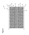
- FIG. 1 is a schematic illustration, in an exemplary embodiment, of a redox polymer energy storage system 10.
- Energy storage system 10 has a sandwich configuration of a plurality of layers. The layers include a first current collector 12 and a second current collector 14. A first electrode 16 formed from carbon nanotubes 18 (CNT) applied to an inner surface 20 of first current collector 12, and a second electrode 22 formed from carbon nanotubes 18 applied to an inner surface 23 of second current collector 14. An ionically conductive separator 24 is positioned between first electrode 16 and second electrode 22.
- CNT carbon nanotubes 18
- Carbon nanotubes 18 have an inherently large surface area and thus a large capacitance (C) because C is proportional to the surface area A of carbon nanotubes 18.
- C ⁇ °A/d where ⁇ is the dielectric permittivity of the electrolyte double layer, ⁇ ° the dielectric permittivity of free space and d is the double layer thickness).
- a polydisulfide is deposited onto the surface of the carbon nanotubes. The polydisulfide enhances the energy storage capability of the electrode by adding a redox capacitance to the existing carbon nanotube capacitance. The magnitude of the redox capacitance is proportional to the molecular density of the disulfide molecule on the carbon nanotube surface.
- An electroactive redox polymer for example, polydisulfide
- polydisulfide is applied to carbon nanotubes 18.
- a disulfide monomer is applied to carbon nanotubes 18, and the disulfide monomer is electro-polymerized to form a polydisulfide on carbon nanotubes 18.
- the polydisulfide may be a poly(2,5-dimercapto-1,3,4-thiadiazole) (polyDMcT).
- Suitable disulfide polymers may include, but not limited to, bis-2,5-dithio-1,3,4-thiadizole, poly(Zn-2,5-dimercapto-1,3,4-thiadiazole), poly(Cu-2,5-dimercapto-1,3,4-thiadiazole), poly(Al-2,5-dimercapto-1,3,4-thiadiazole), poly(Fe-2,5-dimercapto-1,3,4-thiadiazole), and the like.
- Ionically conductive separator 24 transports protons between first electrode 16 and second electrode 22 as storage system is charged and discharged.
- Separator 24 includes an acid polymer gel coated on the surfaces of separator 24.
- the acid polymer gel may be formed from a silicontungstic acid (SiWA).
- the SiWA is dispersed in polyDMcT, and applied to first and second nanotube electrodes 16 and 22. Because only protons are transported through separator 24, high rates of transport are facilitated and provide for low equivalent series resistance (ESR) high power density devices.
- the disulfide for example, 2,5-dimercapto-1,3,4-thiadiazole (DMcT) may be electropolymerized to polyDMcT.
- the DMcT polymerization reaction is reversible as shown below.
- the DMcT is polymerized to polyDMcT during a charging cycle and reverts back to DMcT during a discharge cycle of storage system 10. For example, at the anode electrode DMcT ⁇ polyDMcT, and at the cathode electrode, polyDMcT ⁇ DMcT.
- First current collector 12 and a second current collector 14 may be formed from any conductive material.
- Suitable conductive materials may include, but are not limited to, metals, carbon, graphite, and composite materials, for example, polymers containing carbon fibers or particles, graphite, and metal fibers or particles.
- a redox polymer energy storage system 40 has a sandwich configuration of a plurality of layers as similar to energy storage system 10 described above.
- the layers include a first current collector 42 and a second current collector 44.
- a first electrode 46 formed from carbon nanotubes 48 (CNT) applied to an inner surface 50 of first current collector 42, and a second electrode 52 formed from carbon nanotubes 48 applied to an inner surface 51 of second current collector 44.
- An ionically conductive separator 54 is positioned between first electrode 46 and second electrode 52.
- First electrode 46 includes a polydisulfide deposited onto the surface of the carbon nanotubes 48.
- Second electrode 52 does not include a polydisulfide nor a disulfide.
- Separator 54 includes an acid polymer gel coated on the surfaces of separator 54. The acid polymer gel may be formed from a silicontungstic acid (SiWA).
- the DMcT is polymerized to polyDMcT during a charging cycle and reverts back to DMcT during a discharge cycle of storage system 40.
- DMcT polymerized to polyDMcT during a charging cycle and reverts back to DMcT during a discharge cycle of storage system 40.
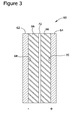
- Type 1 configuration 60 shown in Figure 3 , included two carbon composite electrodes 62 and 64 having a coating 66 of a blend of polyDMcT and SiWA applied to inner surfaces 68 and 70 of electrodes 62 and 64 respectively.
- An ionically conductive separator 72 was positioned between electrodes 62 and 64. Separator 72 was a piece of Whatman 1 qualitative filter paper soaked in SiWA and air dried for about 20 minutes.
- the Type 1 super-capacitor was assembled by stacking electrodes 62 and 64 as shown in Figure 3 with separator 72 between the electrodes.
- Type 2 configuration 80 shown in Figure 4 , included two carbon composite electrodes 82 and 84.
- a coating 86 of a blend of polyDMcT and SiWA was applied to an inner surface 88 of electrode 82.
- a coating 90 of SiWA was applied to an inner surface 92 of electrode 84.
- An ionically conductive separator 94 was positioned between electrodes 82 and 44. Separator 94 was a piece of Whatman 1 qualitative filter paper soaked in SiWA and air dried for about 20 minutes.
- the Type 2 super-capacitor was assembled by stacking electrodes 82 and 84 as shown in Figure 4 with separator 94 between the electrodes.
- Type 3 configuration 100 shown in Figure 5 , included two carbon composite electrodes 102 and 104 having a coating 106 of SiWA applied to inner surfaces 108 and 110 of electrodes 102 and 104 respectively.
- An ionically conductive separator 112 was positioned between electrodes 102 and 104. Separator 112 was a piece of Whatman 1 qualitative filter paper soaked in SiWA and air dried for about 20 minutes.
- the Type 3 super-capacitor was assembled by stacking electrodes 102 and 104 as shown in Figure 5 with separator 112 between the electrodes.
- Cyclic voltammetry was measured for Types 1-3.
- a graph shows the cyclic voltammetry in Figure 6 .
- the graph is an X-Y graph of potential (volts) versus current (amps).
- Chronocoulometry at a charge of 0 to 1.0 volt for 300 seconds was also measured for Types 1-3.
- a graph shows the Chronocoulometry in Figure 7 .
- the graph is an X-Y graph of charge (coulombs) versus time (seconds). As shown in Figures 6 and 7 , configuration Types 1 and 2 showed to be superior to configuration Type 3.
Landscapes
- Engineering & Computer Science (AREA)
- Power Engineering (AREA)
- Chemical & Material Sciences (AREA)
- Chemical Kinetics & Catalysis (AREA)
- Microelectronics & Electronic Packaging (AREA)
- Electrochemistry (AREA)
- General Chemical & Material Sciences (AREA)
- Materials Engineering (AREA)
- Crystallography & Structural Chemistry (AREA)
- Nanotechnology (AREA)
- Manufacturing & Machinery (AREA)
- Electric Double-Layer Capacitors Or The Like (AREA)
- Battery Electrode And Active Subsutance (AREA)
- Secondary Cells (AREA)
- Cell Separators (AREA)
Abstract
Description
- The field of the invention relates generally to a redox polymer energy storage system, and more particularly to the use of electroactive polymers applied to carbon structures.
- Capacitors having a double layer capacitance may be used as energy storage devices that store and release energy. Known double layer capacitors store an amount of energy that is inversely proportional to the thickness of the double layer. At low voltages, these double layer capacitors typically have a higher energy density than conventional dielectric capacitors.
- Lithium ion batteries are also used as energy storage devices. Such batteries typically have very high energy density. Drawbacks of lithium ion batteries are that these batteries need to be hermetically sealed and requires a water free electrolyte composition. In addition, when the lithium ion batteries are spent, the lithium in the battery needs to be sequestered rather than be placed in a waste dump.
- It would be desirable to provide an energy storage system that is a solid state device, has high energy density, is not susceptible to leaking, and is stable at high G-forces and temperature extremes.
- According to an aspect of the present invention there is provided, an energy storage system is provided. The energy storage system includes a first current collector having a first surface and a second surface, a first electrode including a plurality of carbon nanotubes on the second surface of the first current collector. The plurality of carbon nanotubes include a polydisulfide applied onto a surface of the plurality of nanotubes. The energy storage system also includes an ionically conductive separator having a first surface and a second surface, with first surface of the ionically conductive separator positioned on the first electrode, a second current collector having a first surface and a second surface, and a second electrode including a plurality of carbon nanotubes positioned between the first surface of the second current collector and the second surface of the ionically conductive separator.
- Advantageously the plurality of carbon nanotubes of said second electrode comprising a polydisulfide applied onto a surface of said plurality of nanotubes.
- Advantageously the polydisulfide comprises at least one of poly(2,5-dimercapto-1,3,4-thiadiazole), bis-2,5-dithio-1,3,4-thiadizole, poly(Zn-2,5-dimercapto-1,3,4-thiadiazole), poly(Cu-2,5-dimercapto-1,3,4-thiadiazole), poly(Al-2,5-dimercapto-1,3,4-thiadiazole), and poly(Fe-2,5-dimercapto-1,3,4-thiadiazole).
- Advantageously the polydisulfide is electropolymerized from a 2,5-dimercapto-1,3,4-thiadiazole monomer.
- Advantageously the ionically conductive separator comprising an acid polymer gel comprising a silicotungstic acid.
- Advantageously the plurality of carbon nanotubes comprise a combination of a polydisulfide and a silicotungstic acid applied onto a surface of said plurality of nanotubes.
- According to another aspect of the present invention there is provided, an energy storage system is provided. The energy storage system includes a first current collector and a second current collector having a plurality of carbon nanotubes bonded to a surface of the first current collector and the second current collector, a polydisulfide deposited onto the carbon nanotubes of at least one current collector, and an ionically conductive separator sandwiched between the carbon nanotubes of the first current collector and the nanotubes of the second current collector. The separator being configured to transport protons from the carbon nanotubes of the first current collector to the carbon nanotubes of the second current collector.
- Advantageously the plurality of carbon nanotubes of said first and second current collectors comprising said polydisulfide applied onto a surface of said plurality of nanotubes.
- Advantageously the polydisulfide comprises at least one of poly(2,5-dimercapto-1,3,4-thiadiazole), bis-2,5-dithio-1,3,4-thiadizole, poly(Zn-2,5-dimercapto-1,3,4-thiadiazole), poly(Cu-2,5-dimercapto-1,3,4-thiadiazole), poly(Al-2,5-dimercapto-1,3,4-thiadiazole), and poly(Fe-2,5-dimercapto-1,3,4-thiadiazole).
- Advantageously the polydisulfide is electropolymerized from a 2,5-dimercapto-1,3,4-thiadiazole monomer.
- Advantageously the ionically conductive separator comprising an acid polymer gel comprising a silicotungstic acid.
- Advantageously the polydisulfide comprises a combination of a polydisulfide and a silicotungstic acid applied to said nanotubes.
- According to a further aspect of the present invention there is provided, a method of making an energy storage system is provided. The method includes applying a plurality of carbon nanotubes to a surface of a first current collector, applying a plurality of carbon nanotubes to a surface of a second current collector, and coating the carbon nanotubes of at least one of the first current collector and the second current collector with a polydisulfide. The method also includes positioning an ionically conductive separator between the carbon nanotubes applied to the first current collector and the nanotubes applied to the second current collector to form the energy storage system having a sandwich configuration.
- Advantageously the method further comprises applying an acid polymer gel to the ionically conductive separator. Preferably the acid polymer gel comprises a silicotungstic acid.
- Advantageously coating the carbon nanotubes comprises coating the carbon nanotubes of the first current collector and the second current collector with a polydisulfide.
- Advantageously the polydisulfide comprises at least one of poly(2,5-dimercapto-1,3,4-thiadiazole), bis-2,5-dithio-1,3,4-thiadizole, poly(Zn-2,5-dimercapto-1,3,4-thiadiazole), poly(Cu-2,5-dimercapto-1,3,4-thiadiazole), poly(Al-2,5-dimercapto-1,3,4-thiadiazole), and poly(Fe-2,5-dimercapto-1,3,4-thiadiazole).
- Advantageously the method further comprises electropolymerizing a 2,5-dimercapto-1,3,4-thiadiazole monomer to form the polydisulfide.
-
-
Figure 1 is a schematic illustration of an embodiment of a redox polymer energy storage system. -
Figure 2 is a schematic illustration of another embodiment of the redox polymer energy storage system. -
Figure 3 is a schematic illustration of a super-capacitor of a first configuration. -
Figure 4 is a schematic illustration of a super-capacitor of a second configuration. -
Figure 5 is a schematic illustration of a super-capacitor of a third configuration. -
Figure 6 is a graph of cyclic voltammetry of the super-capacitors shown inFigures 3-5 . -
Figure 7 is a graph of chronocoulometry of the super-capacitors shown inFigures 3-5 . - A redox polymer energy storage system and method of making the energy storage system is described in detail below. The energy storage system uses electroactive redox polymers for energy storage, for example, in one embodiment, polydisulfides that are coated and/or otherwise applied to carbon nanotube (CNT) structures. In another embodiment, a disulfide monomer is applied to the CNT structures and may be electro-polymerized to form a polydisulfide. The resulting CNT-polydisulfide structure serves as a redox electrode for the energy storage system. The polymerization reaction of the disulfide monomer is reversible and permits the energy storage system to withstand multiple charge and discharge cycles. The energy storage system includes two current collectors with a first electrode formed from carbon nanotubes, a second electrode of carbon nanotubes, and a transport separator, positioned between the two current collectors. The transport separator is positioned between the first and second electrodes to insulate the electrodes from electrical contact. The energy storage system is a solid state device that does not utilize liquids and thus is not susceptible to leaking and is stable at high G-forces and temperature extremes. In addition, the energy storage device mechanism makes and breaks disulfide bonds, and thus only protons transport during the charge and discharge cycles. Because the transport separator only needs to facilitate proton transport, the transport separator facilitates high power density in the energy storage system.
- Referring to the drawings,
Figure 1 is a schematic illustration, in an exemplary embodiment, of a redox polymerenergy storage system 10.Energy storage system 10 has a sandwich configuration of a plurality of layers. The layers include a firstcurrent collector 12 and a secondcurrent collector 14. Afirst electrode 16 formed from carbon nanotubes 18 (CNT) applied to aninner surface 20 of firstcurrent collector 12, and asecond electrode 22 formed fromcarbon nanotubes 18 applied to aninner surface 23 of secondcurrent collector 14. An ionicallyconductive separator 24 is positioned betweenfirst electrode 16 andsecond electrode 22. -
Carbon nanotubes 18 have an inherently large surface area and thus a large capacitance (C) because C is proportional to the surface area A ofcarbon nanotubes 18. (C = εε°A/d where ε is the dielectric permittivity of the electrolyte double layer, ε° the dielectric permittivity of free space and d is the double layer thickness). To enhance the energy storage capability ofcarbon nanotube electrodes - An electroactive redox polymer, for example, polydisulfide, is applied to
carbon nanotubes 18. In another embodiment, a disulfide monomer is applied tocarbon nanotubes 18, and the disulfide monomer is electro-polymerized to form a polydisulfide oncarbon nanotubes 18. In the exemplary embodiment, the polydisulfide may be a poly(2,5-dimercapto-1,3,4-thiadiazole) (polyDMcT). Other suitable disulfide polymers may include, but not limited to, bis-2,5-dithio-1,3,4-thiadizole, poly(Zn-2,5-dimercapto-1,3,4-thiadiazole), poly(Cu-2,5-dimercapto-1,3,4-thiadiazole), poly(Al-2,5-dimercapto-1,3,4-thiadiazole), poly(Fe-2,5-dimercapto-1,3,4-thiadiazole), and the like. - Ionically
conductive separator 24 transports protons betweenfirst electrode 16 andsecond electrode 22 as storage system is charged and discharged.Separator 24 includes an acid polymer gel coated on the surfaces ofseparator 24. The acid polymer gel may be formed from a silicontungstic acid (SiWA). In another embodiment, the SiWA is dispersed in polyDMcT, and applied to first andsecond nanotube electrodes separator 24, high rates of transport are facilitated and provide for low equivalent series resistance (ESR) high power density devices. The energy ofstorage system 10 may be calculated from the equation C=1/2 (Cdl +Credox)V2, thus the energy is based on the surface area of the CNT and the molecular density of the DMcT. Power density is proportional to V2/4ESR thus as ESR decreases, power density increases. - The disulfide, for example, 2,5-dimercapto-1,3,4-thiadiazole (DMcT), may be electropolymerized to polyDMcT. The DMcT polymerization reaction is reversible as shown below.

storage system 10. For example, at the anode electrode DMcT → polyDMcT, and at the cathode electrode, polyDMcT → DMcT. - First
current collector 12 and a secondcurrent collector 14 may be formed from any conductive material. Suitable conductive materials may include, but are not limited to, metals, carbon, graphite, and composite materials, for example, polymers containing carbon fibers or particles, graphite, and metal fibers or particles. - In another embodiment, as best shown in
Figure 2 , a redox polymerenergy storage system 40 has a sandwich configuration of a plurality of layers as similar toenergy storage system 10 described above. The layers include a firstcurrent collector 42 and a secondcurrent collector 44. Afirst electrode 46 formed from carbon nanotubes 48 (CNT) applied to aninner surface 50 of firstcurrent collector 42, and asecond electrode 52 formed fromcarbon nanotubes 48 applied to aninner surface 51 of secondcurrent collector 44. An ionicallyconductive separator 54 is positioned betweenfirst electrode 46 andsecond electrode 52.First electrode 46 includes a polydisulfide deposited onto the surface of thecarbon nanotubes 48.Second electrode 52 does not include a polydisulfide nor a disulfide.Separator 54 includes an acid polymer gel coated on the surfaces ofseparator 54. The acid polymer gel may be formed from a silicontungstic acid (SiWA). - The DMcT is polymerized to polyDMcT during a charging cycle and reverts back to DMcT during a discharge cycle of
storage system 40. For example, at the anode electrode DMcT → polyDMcT, and at the cathode electrode, H+ → H+ CNT-. - Sample tests were performed to show the ability of super-capacitors to store energy. Three different super-capacitor configurations were tested.
Type 1configuration 60, shown inFigure 3 , included twocarbon composite electrodes coating 66 of a blend of polyDMcT and SiWA applied toinner surfaces electrodes conductive separator 72 was positioned betweenelectrodes Separator 72 was a piece ofWhatman 1 qualitative filter paper soaked in SiWA and air dried for about 20 minutes. TheType 1 super-capacitor was assembled by stackingelectrodes Figure 3 withseparator 72 between the electrodes. -
Type 2configuration 80, shown inFigure 4 , included twocarbon composite electrodes coating 86 of a blend of polyDMcT and SiWA was applied to aninner surface 88 ofelectrode 82. Acoating 90 of SiWA was applied to aninner surface 92 ofelectrode 84. An ionicallyconductive separator 94 was positioned betweenelectrodes Separator 94 was a piece ofWhatman 1 qualitative filter paper soaked in SiWA and air dried for about 20 minutes. TheType 2 super-capacitor was assembled by stackingelectrodes Figure 4 withseparator 94 between the electrodes. -
Type 3configuration 100, shown inFigure 5 , included twocarbon composite electrodes coating 106 of SiWA applied toinner surfaces electrodes conductive separator 112 was positioned betweenelectrodes Separator 112 was a piece ofWhatman 1 qualitative filter paper soaked in SiWA and air dried for about 20 minutes. TheType 3 super-capacitor was assembled by stackingelectrodes Figure 5 withseparator 112 between the electrodes. - Cyclic voltammetry was measured for Types 1-3. A graph shows the cyclic voltammetry in
Figure 6 . The graph is an X-Y graph of potential (volts) versus current (amps). Chronocoulometry at a charge of 0 to 1.0 volt for 300 seconds was also measured for Types 1-3. A graph shows the Chronocoulometry inFigure 7 . The graph is an X-Y graph of charge (coulombs) versus time (seconds). As shown inFigures 6 and7 ,configuration Types configuration Type 3. - This written description uses examples to disclose the invention, including the best mode, and also to enable any person skilled in the art to practice the invention, including making and using any devices or systems and performing any incorporated methods. The patentable scope of the invention is defined by the claims, and may include other examples that occur to those skilled in the art. Such other examples are intended to be within the scope of the claims if they have structural elements that do not differ from the literal language of the claims, or if they include equivalent structural elements with insubstantial differences from the literal language of the claims.
Claims (12)
- An energy storage system comprising:a first current collector 12, 42 having a first surface and a second surface;a first electrode 16, 46 comprising a plurality of carbon nanotubes 18, 48 on said second surface of said first current collector 12, 42, said plurality of carbon nanotubes 18,42 comprising a polydisulfide applied onto a surface of said plurality of nanotubes 18, 42;an ionically conductive separator 24, 54 having a first surface and a second surface, said first surface of said ionically conductive separator 24, 54 positioned on said first electrode 16, 46;a second current collector 14, 44 having a first surface and a second surface; anda second electrode 22, 52 comprising a plurality of carbon nanotubes 18, 48 between said first surface of said second current collector 14, 44and said second surface of said ionically conductive separator 24, 54.
- The energy storage system in accordance with Claim 1 wherein said plurality of carbon nanotubes 18, 48 of said second electrode 22, 52 comprising a polydisulfide applied onto a surface of said plurality of nanotubes 18, 48.
- The energy storage system in accordance with Claim 1 wherein said polydisulfide comprises at least one of poly(2,5-dimercapto-1,3,4-thiadiazole), bis-2,5-dithio-1,3,4-thiadizole, poly(Zn-2,5-dimercapto-1,3,4-thiadiazole), poly(Cu-2,5-dimercapto-1,3,4-thiadiazole), poly(Al-2,5-dimercapto-1,3,4-thiadiazole), and poly(Fe-2,5-dimercapto-1,3,4-thiadiazole).
- The energy storage system in accordance with Claim 1 wherein said polydisulfide is electropolymerized from a 2,5-dimercapto-1,3,4-thiadiazole monomer.
- The energy storage system in accordance with Claim 1 wherein said ionically conductive separator 24, 54 comprising an acid polymer gel comprising a silicotungstic acid.
- The energy storage system in accordance with Claim 1 wherein said plurality of carbon nanotubes 18, 48 comprise a combination of a polydisulfide and a silicotungstic acid applied onto a surface of said plurality of nanotubes 18, 48.
- A method of making an energy storage system, said method comprising:applying a plurality of carbon nanotubes 18, 48 to a surface of a first current collector 12, 42;applying a plurality of carbon nanotubes 18, 48 to a surface of a second current collector 14, 44;coating the carbon nanotubes 18, 48 of at least one of the first current collector 12, 42 and the second current collector 14, 44 with a polydisulfide; andpositioning an ionically conductive separator 24, 54 between the carbon nanotubes 18, 48 applied to the first current collector 12, 42 and the nanotubes 18, 48 applied to the second current collector 14, 44 to form the energy storage system having a sandwich configuration.
- The method in accordance with Claim 7 further comprising applying an acid polymer gel to the ionically conductive separator 24, 54.
- The method in accordance with Claim 8 wherein the acid polymer gel comprises a silicotungstic acid.
- The method in accordance with Claim 7 wherein coating the carbon nanotubes 18, 48 comprises coating the carbon nanotubes 18, 48 of the first current collector 12, 42 and the second current collector 14, 44 with a polydisulfide.
- The method in accordance with Claim 7 wherein the polydisulfide comprises at least one of poly(2,5-dimercapto-1,3,4-thiadiazole), bis-2,5-dithio-1,3,4-thiadizole, poly(Zn-2,5-dimercapto-1,3,4-thiadiazole), poly(Cu-2,5-dimercapto-1,3,4-thiadiazole), poly(Al-2,5-dimercapto-1,3,4-thiadiazole), and poly(Fe-2,5-dimercapto-1,3,4-thiadiazole).
- The method in accordance with Claim 7 further comprising electropolymerizing a 2,5-dimercapto-1,3,4-thiadiazole monomer to form the polydisulfide.
Applications Claiming Priority (1)
| Application Number | Priority Date | Filing Date | Title |
|---|---|---|---|
| US13/426,692 US9325041B2 (en) | 2012-03-22 | 2012-03-22 | Redox polymer energy storage system |
Publications (2)
| Publication Number | Publication Date |
|---|---|
| EP2642567A1 true EP2642567A1 (en) | 2013-09-25 |
| EP2642567B1 EP2642567B1 (en) | 2014-12-17 |
Family
ID=47901825
Family Applications (1)
| Application Number | Title | Priority Date | Filing Date |
|---|---|---|---|
| EP13159818.7A Not-in-force EP2642567B1 (en) | 2012-03-22 | 2013-03-18 | Redox polymer energy storage system |
Country Status (4)
| Country | Link |
|---|---|
| US (2) | US9325041B2 (en) |
| EP (1) | EP2642567B1 (en) |
| JP (1) | JP6242577B2 (en) |
| CN (1) | CN103325580B (en) |
Families Citing this family (2)
| Publication number | Priority date | Publication date | Assignee | Title |
|---|---|---|---|---|
| LT6239B (en) | 2015-04-17 | 2016-01-11 | Valstybinis mokslinių tyrimų institutas Fizinių ir technologijos mokslų centras | Pyrrolo bio-polymerization using redox mediator |
| US12119176B2 (en) * | 2021-02-19 | 2024-10-15 | Micron Technology, Inc. | Supercapacitors and integrated assemblies containing supercapacitors |
Citations (3)
| Publication number | Priority date | Publication date | Assignee | Title |
|---|---|---|---|---|
| US20030030963A1 (en) * | 1996-05-15 | 2003-02-13 | Howard Tennent | Graphitic nanofibers in electrochemical capacitors |
| EP1484809A1 (en) * | 2002-02-07 | 2004-12-08 | Noboru Oyama | Redox active reversible electrode and novel cell using it |
| EP1978053A1 (en) * | 2006-01-27 | 2008-10-08 | Fuji Jukogyo Kabushiki Kaisha | Process for the production of sulfur-containing aromatic polymers |
Family Cites Families (13)
| Publication number | Priority date | Publication date | Assignee | Title |
|---|---|---|---|---|
| US4031436A (en) * | 1975-05-09 | 1977-06-21 | United Chemi-Con, Inc. | Electrolyte capacitors |
| US4107059A (en) | 1977-06-27 | 1978-08-15 | Pennwalt Corporation | Polymer of 1,2,4-thiadiazole and lubricants containing it as an additive |
| EP0058134B1 (en) | 1981-02-05 | 1983-12-07 | Sandoz Ag | Novel bis- and poly-disulfides having immunostimulant activity |
| US5247061A (en) | 1992-07-22 | 1993-09-21 | Phillips Petroleum Company | Synthesis of poly(dithio thiadiazole by oxidative polymerization |
| US6703163B2 (en) * | 1998-03-31 | 2004-03-09 | Celanese Ventures Gmbh | Lithium battery and electrode |
| JPH11329414A (en) * | 1998-03-31 | 1999-11-30 | Aventis Res & Technol Gmbh & Co Kg | Lithium battery and electrode |
| EP1387421A4 (en) | 2001-03-30 | 2004-04-21 | Katsuhiko Naoi | ENERGY STORAGE DEVICE MATERIAL OBTAINED FROM A HETEROCYCLIC ORGANIC SULFUR COMPOUND AND ITS DESIGN METHOD |
| JP4416419B2 (en) * | 2003-03-10 | 2010-02-17 | 三洋電機株式会社 | Alkaline storage battery separator and alkaline storage battery |
| US20090262484A1 (en) * | 2005-09-29 | 2009-10-22 | Kabushikikaisha Equos Research | Capacitor, Capacitor Electrode, and Mehtod of Manufacturing Capacitor Electrode Material |
| JP5099299B2 (en) * | 2006-02-28 | 2012-12-19 | 株式会社エクォス・リサーチ | Positive electrode material for lithium secondary battery, method for producing the same, and lithium secondary battery |
| JP2009277760A (en) * | 2008-05-13 | 2009-11-26 | Equos Research Co Ltd | Electrode for faraday capacitance type capacitor and method of manufacturing the same, and faraday capacitance type capacitor |
| US20120154980A1 (en) | 2009-11-17 | 2012-06-21 | Lumimove, Inc., D/B/A Crosslink | Conductive polymer composites |
| JP5533035B2 (en) * | 2010-03-02 | 2014-06-25 | ソニー株式会社 | Nonaqueous electrolyte composition and nonaqueous electrolyte battery |
-
2012
- 2012-03-22 US US13/426,692 patent/US9325041B2/en not_active Expired - Fee Related
-
2013
- 2013-03-18 EP EP13159818.7A patent/EP2642567B1/en not_active Not-in-force
- 2013-03-21 JP JP2013058000A patent/JP6242577B2/en not_active Expired - Fee Related
- 2013-03-21 CN CN201310091287.9A patent/CN103325580B/en not_active Expired - Fee Related
-
2016
- 2016-02-11 US US15/041,762 patent/US9728346B2/en not_active Expired - Fee Related
Patent Citations (3)
| Publication number | Priority date | Publication date | Assignee | Title |
|---|---|---|---|---|
| US20030030963A1 (en) * | 1996-05-15 | 2003-02-13 | Howard Tennent | Graphitic nanofibers in electrochemical capacitors |
| EP1484809A1 (en) * | 2002-02-07 | 2004-12-08 | Noboru Oyama | Redox active reversible electrode and novel cell using it |
| EP1978053A1 (en) * | 2006-01-27 | 2008-10-08 | Fuji Jukogyo Kabushiki Kaisha | Process for the production of sulfur-containing aromatic polymers |
Also Published As
| Publication number | Publication date |
|---|---|
| CN103325580B (en) | 2017-08-18 |
| CN103325580A (en) | 2013-09-25 |
| US9728346B2 (en) | 2017-08-08 |
| EP2642567B1 (en) | 2014-12-17 |
| JP2013197595A (en) | 2013-09-30 |
| US20160163471A1 (en) | 2016-06-09 |
| US20130250484A1 (en) | 2013-09-26 |
| US9325041B2 (en) | 2016-04-26 |
| JP6242577B2 (en) | 2017-12-06 |
Similar Documents
| Publication | Publication Date | Title |
|---|---|---|
| Lewandowski et al. | Supercapacitor based on activated carbon and polyethylene oxide–KOH–H2O polymer electrolyte | |
| US11791470B2 (en) | Battery cell with electrolyte diffusion material | |
| Anothumakkool et al. | Electrodeposited polyethylenedioxythiophene with infiltrated gel electrolyte interface: a close contest of an all-solid-state supercapacitor with its liquid-state counterpart | |
| Bhattacharjya et al. | Study of electrode processing and cell assembly for the optimized performance of supercapacitor in pouch cell configuration | |
| JP2012517660A (en) | Flat electrodes for electrochemical energy storage elements with optimized power and energy density | |
| US10312028B2 (en) | Electrochemical energy storage devices and manufacturing methods | |
| KR20100129307A (en) | Electrode Membrane and Electrode Containing Ionic Liquid, Manufacturing Method thereof, and Storage Device | |
| JP2012169576A (en) | Electrochemical device | |
| KR20200005494A (en) | Grid current collector and associated devices and methods | |
| US9030804B2 (en) | Accumulator device | |
| US7623339B2 (en) | Electrochemical device | |
| KR101059891B1 (en) | High power electrical energy storage device having a unit cell and the unit cell | |
| EP2642567B1 (en) | Redox polymer energy storage system | |
| JP6723261B2 (en) | Electric double layer element | |
| US20170279166A1 (en) | Lithium-Ion Cell | |
| KR101599711B1 (en) | Electric double layer device | |
| KR102568421B1 (en) | Membrane electrode assembly and zinc-bromide supercapattery comprising the same | |
| Ho et al. | Dispenser printed electrochemical capacitors for power management of millimeter scale lithium ion polymer microbatteries for wireless sensors | |
| JP6577249B2 (en) | Evaluation cell and evaluation method | |
| KR101558959B1 (en) | Liquid electrolyte solution having voltage stability by addition of sulfolane or ionic liquid and high voltage supercapacitor using the same | |
| Wu et al. | Aqueous based solid battery-capacitor asymmetrical system for capacitive energy storage device | |
| JP2005064207A (en) | Electrochemical device and method for producing electrochemical device | |
| RU2810656C1 (en) | Electrochemical storage of electrical energy and method of its manufacture | |
| JP2017073462A (en) | Electrochemical device | |
| US10601045B1 (en) | Porous carbon electrode assembly for electrochemical devices |
Legal Events
| Date | Code | Title | Description |
|---|---|---|---|
| PUAI | Public reference made under article 153(3) epc to a published international application that has entered the european phase |
Free format text: ORIGINAL CODE: 0009012 |
|
| 17P | Request for examination filed |
Effective date: 20130318 |
|
| AK | Designated contracting states |
Kind code of ref document: A1 Designated state(s): AL AT BE BG CH CY CZ DE DK EE ES FI FR GB GR HR HU IE IS IT LI LT LU LV MC MK MT NL NO PL PT RO RS SE SI SK SM TR |
|
| AX | Request for extension of the european patent |
Extension state: BA ME |
|
| GRAP | Despatch of communication of intention to grant a patent |
Free format text: ORIGINAL CODE: EPIDOSNIGR1 |
|
| RIC1 | Information provided on ipc code assigned before grant |
Ipc: H01G 11/52 20130101ALI20140606BHEP Ipc: H01M 4/60 20060101AFI20140606BHEP Ipc: H01G 11/36 20130101ALI20140606BHEP Ipc: H01G 11/02 20130101ALI20140606BHEP Ipc: H01M 14/00 20060101ALI20140606BHEP Ipc: H01G 11/56 20130101ALI20140606BHEP Ipc: H01G 11/48 20130101ALI20140606BHEP |
|
| INTG | Intention to grant announced |
Effective date: 20140703 |
|
| GRAS | Grant fee paid |
Free format text: ORIGINAL CODE: EPIDOSNIGR3 |
|
| GRAA | (expected) grant |
Free format text: ORIGINAL CODE: 0009210 |
|
| AK | Designated contracting states |
Kind code of ref document: B1 Designated state(s): AL AT BE BG CH CY CZ DE DK EE ES FI FR GB GR HR HU IE IS IT LI LT LU LV MC MK MT NL NO PL PT RO RS SE SI SK SM TR |
|
| REG | Reference to a national code |
Ref country code: GB Ref legal event code: FG4D |
|
| REG | Reference to a national code |
Ref country code: CH Ref legal event code: EP |
|
| REG | Reference to a national code |
Ref country code: IE Ref legal event code: FG4D |
|
| REG | Reference to a national code |
Ref country code: AT Ref legal event code: REF Ref document number: 702445 Country of ref document: AT Kind code of ref document: T Effective date: 20150115 |
|
| REG | Reference to a national code |
Ref country code: DE Ref legal event code: R096 Ref document number: 602013000611 Country of ref document: DE Effective date: 20150205 |
|
| PG25 | Lapsed in a contracting state [announced via postgrant information from national office to epo] |
Ref country code: FI Free format text: LAPSE BECAUSE OF FAILURE TO SUBMIT A TRANSLATION OF THE DESCRIPTION OR TO PAY THE FEE WITHIN THE PRESCRIBED TIME-LIMIT Effective date: 20141217 Ref country code: LT Free format text: LAPSE BECAUSE OF FAILURE TO SUBMIT A TRANSLATION OF THE DESCRIPTION OR TO PAY THE FEE WITHIN THE PRESCRIBED TIME-LIMIT Effective date: 20141217 Ref country code: NO Free format text: LAPSE BECAUSE OF FAILURE TO SUBMIT A TRANSLATION OF THE DESCRIPTION OR TO PAY THE FEE WITHIN THE PRESCRIBED TIME-LIMIT Effective date: 20150317 |
|
| REG | Reference to a national code |
Ref country code: LT Ref legal event code: MG4D |
|
| PG25 | Lapsed in a contracting state [announced via postgrant information from national office to epo] |
Ref country code: HR Free format text: LAPSE BECAUSE OF FAILURE TO SUBMIT A TRANSLATION OF THE DESCRIPTION OR TO PAY THE FEE WITHIN THE PRESCRIBED TIME-LIMIT Effective date: 20141217 Ref country code: GR Free format text: LAPSE BECAUSE OF FAILURE TO SUBMIT A TRANSLATION OF THE DESCRIPTION OR TO PAY THE FEE WITHIN THE PRESCRIBED TIME-LIMIT Effective date: 20150318 Ref country code: RS Free format text: LAPSE BECAUSE OF FAILURE TO SUBMIT A TRANSLATION OF THE DESCRIPTION OR TO PAY THE FEE WITHIN THE PRESCRIBED TIME-LIMIT Effective date: 20141217 Ref country code: LV Free format text: LAPSE BECAUSE OF FAILURE TO SUBMIT A TRANSLATION OF THE DESCRIPTION OR TO PAY THE FEE WITHIN THE PRESCRIBED TIME-LIMIT Effective date: 20141217 Ref country code: SE Free format text: LAPSE BECAUSE OF FAILURE TO SUBMIT A TRANSLATION OF THE DESCRIPTION OR TO PAY THE FEE WITHIN THE PRESCRIBED TIME-LIMIT Effective date: 20141217 |
|
| REG | Reference to a national code |
Ref country code: AT Ref legal event code: MK05 Ref document number: 702445 Country of ref document: AT Kind code of ref document: T Effective date: 20141217 |
|
| PG25 | Lapsed in a contracting state [announced via postgrant information from national office to epo] |
Ref country code: NL Free format text: LAPSE BECAUSE OF FAILURE TO SUBMIT A TRANSLATION OF THE DESCRIPTION OR TO PAY THE FEE WITHIN THE PRESCRIBED TIME-LIMIT Effective date: 20141217 |
|
| PG25 | Lapsed in a contracting state [announced via postgrant information from national office to epo] |
Ref country code: EE Free format text: LAPSE BECAUSE OF FAILURE TO SUBMIT A TRANSLATION OF THE DESCRIPTION OR TO PAY THE FEE WITHIN THE PRESCRIBED TIME-LIMIT Effective date: 20141217 Ref country code: RO Free format text: LAPSE BECAUSE OF FAILURE TO SUBMIT A TRANSLATION OF THE DESCRIPTION OR TO PAY THE FEE WITHIN THE PRESCRIBED TIME-LIMIT Effective date: 20141217 Ref country code: CZ Free format text: LAPSE BECAUSE OF FAILURE TO SUBMIT A TRANSLATION OF THE DESCRIPTION OR TO PAY THE FEE WITHIN THE PRESCRIBED TIME-LIMIT Effective date: 20141217 Ref country code: ES Free format text: LAPSE BECAUSE OF FAILURE TO SUBMIT A TRANSLATION OF THE DESCRIPTION OR TO PAY THE FEE WITHIN THE PRESCRIBED TIME-LIMIT Effective date: 20141217 Ref country code: SK Free format text: LAPSE BECAUSE OF FAILURE TO SUBMIT A TRANSLATION OF THE DESCRIPTION OR TO PAY THE FEE WITHIN THE PRESCRIBED TIME-LIMIT Effective date: 20141217 |
|
| PG25 | Lapsed in a contracting state [announced via postgrant information from national office to epo] |
Ref country code: IS Free format text: LAPSE BECAUSE OF FAILURE TO SUBMIT A TRANSLATION OF THE DESCRIPTION OR TO PAY THE FEE WITHIN THE PRESCRIBED TIME-LIMIT Effective date: 20150417 Ref country code: PL Free format text: LAPSE BECAUSE OF FAILURE TO SUBMIT A TRANSLATION OF THE DESCRIPTION OR TO PAY THE FEE WITHIN THE PRESCRIBED TIME-LIMIT Effective date: 20141217 Ref country code: AT Free format text: LAPSE BECAUSE OF FAILURE TO SUBMIT A TRANSLATION OF THE DESCRIPTION OR TO PAY THE FEE WITHIN THE PRESCRIBED TIME-LIMIT Effective date: 20141217 |
|
| REG | Reference to a national code |
Ref country code: DE Ref legal event code: R097 Ref document number: 602013000611 Country of ref document: DE |
|
| PLBE | No opposition filed within time limit |
Free format text: ORIGINAL CODE: 0009261 |
|
| STAA | Information on the status of an ep patent application or granted ep patent |
Free format text: STATUS: NO OPPOSITION FILED WITHIN TIME LIMIT |
|
| PG25 | Lapsed in a contracting state [announced via postgrant information from national office to epo] |
Ref country code: MC Free format text: LAPSE BECAUSE OF FAILURE TO SUBMIT A TRANSLATION OF THE DESCRIPTION OR TO PAY THE FEE WITHIN THE PRESCRIBED TIME-LIMIT Effective date: 20141217 Ref country code: DK Free format text: LAPSE BECAUSE OF FAILURE TO SUBMIT A TRANSLATION OF THE DESCRIPTION OR TO PAY THE FEE WITHIN THE PRESCRIBED TIME-LIMIT Effective date: 20141217 Ref country code: LU Free format text: LAPSE BECAUSE OF FAILURE TO SUBMIT A TRANSLATION OF THE DESCRIPTION OR TO PAY THE FEE WITHIN THE PRESCRIBED TIME-LIMIT Effective date: 20150318 |
|
| 26N | No opposition filed |
Effective date: 20150918 |
|
| PG25 | Lapsed in a contracting state [announced via postgrant information from national office to epo] |
Ref country code: IT Free format text: LAPSE BECAUSE OF FAILURE TO SUBMIT A TRANSLATION OF THE DESCRIPTION OR TO PAY THE FEE WITHIN THE PRESCRIBED TIME-LIMIT Effective date: 20141217 |
|
| REG | Reference to a national code |
Ref country code: IE Ref legal event code: MM4A |
|
| PG25 | Lapsed in a contracting state [announced via postgrant information from national office to epo] |
Ref country code: IE Free format text: LAPSE BECAUSE OF NON-PAYMENT OF DUE FEES Effective date: 20150318 |
|
| PG25 | Lapsed in a contracting state [announced via postgrant information from national office to epo] |
Ref country code: SI Free format text: LAPSE BECAUSE OF FAILURE TO SUBMIT A TRANSLATION OF THE DESCRIPTION OR TO PAY THE FEE WITHIN THE PRESCRIBED TIME-LIMIT Effective date: 20141217 |
|
| REG | Reference to a national code |
Ref country code: FR Ref legal event code: PLFP Year of fee payment: 4 |
|
| PG25 | Lapsed in a contracting state [announced via postgrant information from national office to epo] |
Ref country code: BE Free format text: LAPSE BECAUSE OF FAILURE TO SUBMIT A TRANSLATION OF THE DESCRIPTION OR TO PAY THE FEE WITHIN THE PRESCRIBED TIME-LIMIT Effective date: 20141217 |
|
| REG | Reference to a national code |
Ref country code: CH Ref legal event code: PL |
|
| PG25 | Lapsed in a contracting state [announced via postgrant information from national office to epo] |
Ref country code: MT Free format text: LAPSE BECAUSE OF FAILURE TO SUBMIT A TRANSLATION OF THE DESCRIPTION OR TO PAY THE FEE WITHIN THE PRESCRIBED TIME-LIMIT Effective date: 20141217 |
|
| PG25 | Lapsed in a contracting state [announced via postgrant information from national office to epo] |
Ref country code: LI Free format text: LAPSE BECAUSE OF NON-PAYMENT OF DUE FEES Effective date: 20160331 Ref country code: CH Free format text: LAPSE BECAUSE OF NON-PAYMENT OF DUE FEES Effective date: 20160331 |
|
| REG | Reference to a national code |
Ref country code: FR Ref legal event code: PLFP Year of fee payment: 5 |
|
| PG25 | Lapsed in a contracting state [announced via postgrant information from national office to epo] |
Ref country code: BG Free format text: LAPSE BECAUSE OF FAILURE TO SUBMIT A TRANSLATION OF THE DESCRIPTION OR TO PAY THE FEE WITHIN THE PRESCRIBED TIME-LIMIT Effective date: 20141217 Ref country code: HU Free format text: LAPSE BECAUSE OF FAILURE TO SUBMIT A TRANSLATION OF THE DESCRIPTION OR TO PAY THE FEE WITHIN THE PRESCRIBED TIME-LIMIT; INVALID AB INITIO Effective date: 20130318 |
|
| PG25 | Lapsed in a contracting state [announced via postgrant information from national office to epo] |
Ref country code: CY Free format text: LAPSE BECAUSE OF FAILURE TO SUBMIT A TRANSLATION OF THE DESCRIPTION OR TO PAY THE FEE WITHIN THE PRESCRIBED TIME-LIMIT Effective date: 20141217 |
|
| PG25 | Lapsed in a contracting state [announced via postgrant information from national office to epo] |
Ref country code: TR Free format text: LAPSE BECAUSE OF FAILURE TO SUBMIT A TRANSLATION OF THE DESCRIPTION OR TO PAY THE FEE WITHIN THE PRESCRIBED TIME-LIMIT Effective date: 20141217 |
|
| REG | Reference to a national code |
Ref country code: FR Ref legal event code: PLFP Year of fee payment: 6 |
|
| PG25 | Lapsed in a contracting state [announced via postgrant information from national office to epo] |
Ref country code: SM Free format text: LAPSE BECAUSE OF FAILURE TO SUBMIT A TRANSLATION OF THE DESCRIPTION OR TO PAY THE FEE WITHIN THE PRESCRIBED TIME-LIMIT Effective date: 20141217 |
|
| PG25 | Lapsed in a contracting state [announced via postgrant information from national office to epo] |
Ref country code: MK Free format text: LAPSE BECAUSE OF FAILURE TO SUBMIT A TRANSLATION OF THE DESCRIPTION OR TO PAY THE FEE WITHIN THE PRESCRIBED TIME-LIMIT Effective date: 20141217 |
|
| PG25 | Lapsed in a contracting state [announced via postgrant information from national office to epo] |
Ref country code: PT Free format text: LAPSE BECAUSE OF FAILURE TO SUBMIT A TRANSLATION OF THE DESCRIPTION OR TO PAY THE FEE WITHIN THE PRESCRIBED TIME-LIMIT Effective date: 20141217 |
|
| PG25 | Lapsed in a contracting state [announced via postgrant information from national office to epo] |
Ref country code: AL Free format text: LAPSE BECAUSE OF FAILURE TO SUBMIT A TRANSLATION OF THE DESCRIPTION OR TO PAY THE FEE WITHIN THE PRESCRIBED TIME-LIMIT Effective date: 20141217 |
|
| PGFP | Annual fee paid to national office [announced via postgrant information from national office to epo] |
Ref country code: FR Payment date: 20230327 Year of fee payment: 11 |
|
| PGFP | Annual fee paid to national office [announced via postgrant information from national office to epo] |
Ref country code: GB Payment date: 20230327 Year of fee payment: 11 Ref country code: DE Payment date: 20230329 Year of fee payment: 11 |
|
| P01 | Opt-out of the competence of the unified patent court (upc) registered |
Effective date: 20230516 |
|
| REG | Reference to a national code |
Ref country code: DE Ref legal event code: R119 Ref document number: 602013000611 Country of ref document: DE |
|
| GBPC | Gb: european patent ceased through non-payment of renewal fee |
Effective date: 20240318 |
|
| PG25 | Lapsed in a contracting state [announced via postgrant information from national office to epo] |
Ref country code: DE Free format text: LAPSE BECAUSE OF NON-PAYMENT OF DUE FEES Effective date: 20241001 |
|
| PG25 | Lapsed in a contracting state [announced via postgrant information from national office to epo] |
Ref country code: GB Free format text: LAPSE BECAUSE OF NON-PAYMENT OF DUE FEES Effective date: 20240318 |
|
| PG25 | Lapsed in a contracting state [announced via postgrant information from national office to epo] |
Ref country code: FR Free format text: LAPSE BECAUSE OF NON-PAYMENT OF DUE FEES Effective date: 20240331 |
|
| PG25 | Lapsed in a contracting state [announced via postgrant information from national office to epo] |
Ref country code: GB Free format text: LAPSE BECAUSE OF NON-PAYMENT OF DUE FEES Effective date: 20240318 Ref country code: FR Free format text: LAPSE BECAUSE OF NON-PAYMENT OF DUE FEES Effective date: 20240331 Ref country code: DE Free format text: LAPSE BECAUSE OF NON-PAYMENT OF DUE FEES Effective date: 20241001 |