EP2642423B1 - Combined multifunctional RFID communication device - Google Patents
Combined multifunctional RFID communication device Download PDFInfo
- Publication number
- EP2642423B1 EP2642423B1 EP12160850.9A EP12160850A EP2642423B1 EP 2642423 B1 EP2642423 B1 EP 2642423B1 EP 12160850 A EP12160850 A EP 12160850A EP 2642423 B1 EP2642423 B1 EP 2642423B1
- Authority
- EP
- European Patent Office
- Prior art keywords
- antenna
- rfid
- sub
- tag
- iec
- Prior art date
- Legal status (The legal status is an assumption and is not a legal conclusion. Google has not performed a legal analysis and makes no representation as to the accuracy of the status listed.)
- Not-in-force
Links
Images
Classifications
-
- G—PHYSICS
- G06—COMPUTING; CALCULATING OR COUNTING
- G06K—GRAPHICAL DATA READING; PRESENTATION OF DATA; RECORD CARRIERS; HANDLING RECORD CARRIERS
- G06K7/00—Methods or arrangements for sensing record carriers, e.g. for reading patterns
- G06K7/10—Methods or arrangements for sensing record carriers, e.g. for reading patterns by electromagnetic radiation, e.g. optical sensing; by corpuscular radiation
- G06K7/10009—Methods or arrangements for sensing record carriers, e.g. for reading patterns by electromagnetic radiation, e.g. optical sensing; by corpuscular radiation sensing by radiation using wavelengths larger than 0.1 mm, e.g. radio-waves or microwaves
- G06K7/10297—Methods or arrangements for sensing record carriers, e.g. for reading patterns by electromagnetic radiation, e.g. optical sensing; by corpuscular radiation sensing by radiation using wavelengths larger than 0.1 mm, e.g. radio-waves or microwaves arrangements for handling protocols designed for non-contact record carriers such as RFIDs NFCs, e.g. ISO/IEC 14443 and 18092
-
- G—PHYSICS
- G06—COMPUTING; CALCULATING OR COUNTING
- G06K—GRAPHICAL DATA READING; PRESENTATION OF DATA; RECORD CARRIERS; HANDLING RECORD CARRIERS
- G06K7/00—Methods or arrangements for sensing record carriers, e.g. for reading patterns
- G06K7/0008—General problems related to the reading of electronic memory record carriers, independent of its reading method, e.g. power transfer
-
- H—ELECTRICITY
- H01—ELECTRIC ELEMENTS
- H01F—MAGNETS; INDUCTANCES; TRANSFORMERS; SELECTION OF MATERIALS FOR THEIR MAGNETIC PROPERTIES
- H01F38/00—Adaptations of transformers or inductances for specific applications or functions
- H01F38/14—Inductive couplings
Description
- The present invention relates to the field of communication with RFID-tags, e.g. within a home appliance, such as a washing machine or a refrigerator.
- Modern home appliances or white good devices tend to incorporate an increasing amount of smartness. One possible future smart aspect of home appliances could be the ability to adapt its behavior to particular content, i.e. to the items that are within the home appliance. A washing machine, for example, may be able to adapt its washing program in accordance with the particular laundry that is supplied to the machine and the kind of detergent that is intended to be used.
- For such a washing machine, at least two communications with the physical world would be necessarily foreseen. In order to calculate the optimal washing program, the machine needs to obtain information on at least (a) the characteristics of the particular laundry and (b) the washing powder or detergent. If necessary, the machine could prompt the user to apply a different washing powder or to remove some clothes or other items of laundry that are not compatible with the calculated program.
- One way for the washing machine to obtain the needed information could be to read it from RFID-tags attached e.g. to the respective pieces of laundry and to the detergent box or container. The RFID-tags or labels of the respective pieces of laundry would then have to contain corresponding typical fabric characteristics, like washing and ironing instructions. Similarly, the RFID-tag of the detergent box would have to contain information identifying the particular detergent product and its characteristics.
- When the pieces of laundry are supplied into the machine, an RFID-reader could detect each corresponding tag and read the data contents of the tag. Similarly, the box with washing powder could be held close to another RFID reader to let the machine know the kind of detergent that is intended to be used.
- For obtaining these two information streams, the machine would need two antennas, e.g. a standard NFC (Near Field Communication) antenna like the ones applied in standard card readers to read the RFID-tag of the detergent box, and another antenna provided around the entrance opening of the machine to read the tags of the laundry items. These antennas are connected to respective dedicated reader ICs which are subsequently connected to a control unit.
-
US 7 973 645 B 1 describes an RFID reader device connected to a plurality of RFID antenna modules and comprising an RF signal generator and a select signal generator. The select signal generator is operable to select one or more of the plurality of RFID antenna modules. -
US 7592898 B1 describes a wireless communication system which includes an interrogator including a housing including circuitry configured to generate a forward link communication signal; communication circuitry configured to communicate the forward link communication signal; and a communication station remotely located with respect to the housing and configured to receive the forward link communication signal from the communication circuitry and to radiate a forward link wireless signal corresponding to the forward link communication signal; and at least one remote communication device configured to receive the forward link wireless signal. -
US 2006052055 A1 describes a computer program stored in a memory unit of an electronic near field communication module for near field communication devices in environments with different data formats according to different protocols, which is able to carry out a first initiation operation using a first data format according to a protocol of a first standard, a second initiation operation using a second data format according to a protocol of a second standard, a delay operation, and is able to repeat these operations in a repetitive process. Such devices can search their environment periodically for available RFID tags, RFID readers, NFC multifunctional devices, or the like. The delay can be fixed, variable in length, or both fixed and variable delays can be used. The invention enables for instance a mobile phone to act as an RFID reader of multiple tag formats, to emulate a tag, or to communicate with other NFC devices. -
US 2004090310 A1 describes an electronic radio frequency (RF) identification system, which includes an interrogator and a plurality of RF transponders. In use, each transponder is operative in response to an interrogation signal to respond with a forward error correctable data message including base data encoded as symbol characters in accordance with a forward error correcting code, such as a Reed Solomon Code, and check characters on the base data as defined in the forward error correcting code. The interrogator utilizes data relating to the forward error correcting code, the symbol characters and check characters in the received forward error correctable data message, to reconstruct the base data in the event of corruption of the forward error correctable data message during transmission. -
US 2004046642 A1 describes a tagging system which includes a tag reader and a plurality of RFID tags. The tag reader addresses a group of RFID tags, and the group of RFID tags is a subset of the plurality of RFID tags. Each of the RFID tags in the plurality of RFID tags has a unique identifier. The tag reader transmits a group address having first and second sets of data elements. The data elements in the first set of data elements are substantially equal in value to corresponding ones of the data elements in the identifiers of the group of RFID tags. The data elements in the second set of data elements represent any value for corresponding ones of the data elements in the identifiers of the group of RFID tags. Only the RFID tags having corresponding data elements in their identifiers that match the first set of data elements in the group address respond. -
DE 102004038685 A1 describes an arrangement for identification of small objects which are provided with transponders for recognition of objects, and at a target location a reception unit is provided for identifying the objects. For localizing the objects in reference to the target location of one group of objects, a reception unit is provided for detecting different reception frequencies and is assigned selectively, discrete target locations and radio signals sent by the transponders can be received by the reception unit at different frequencies. -
EP 0 496 609 A1 describes that, where a signal is to be sent to a transponder passing by an interrogation station, the station should include two window antennas mutually rectangular to each other driven by two carrier signals at the same frequency mutually 90 DEG phase shifted such that a rotating field comes about in the interrogation passage associated with the station. - There is a need for a simple and inexpensive way for e.g. a home appliance or white good device to communicate with RFID-tags of various items.
- The invention is defined by claim 1 which has been delimited against
US 7,592,898 . - Preferred embodiments are set out in the dependent claims.
- The invention is based on the idea that a single controller feeds a sequence of different polling signals to the antenna unit such that both the first antenna and the second antenna simultaneously radiate corresponding polling signals. In other words, both the first antenna and the second antenna radiate an identical sequence of different polling signals simultaneously, i.e. in parallel. Thereby, if an RFID-tag is placed within range of either of the first antenna and the second antenna, the RFID-tag may at some point during the sequence receive a polling signal to which the particular RFID-tag is sensitive.
- In the present context, the term "RFID-tag" may particularly denote a device (in the shape of e.g. a sticker, button, batch or card) which is capable of being powered by an electromagnetic field or wave. Different from a corresponding reader (e.g. in a fixed environment or in a mobile phone), an RFID-tag does have its own power supply.
- In the present context, the term "sequence of different polling signals" may particularly denote a series of at least two different polling signals which are generated (i.e. fed to the antenna unit or radiated by the first antenna and by the second antenna of the antenna unit) at different points in time. These different points in time may preferably be separated by an amount of time which is sufficient to transmit one of the different polling signals and to allow an RFID-tag to react to the polling signal. The sequence of polling signals may be a random sequence or a predetermined sequence. In case of a predetermined sequence, the sequence is preferably repeated after each completion of the sequence. The different polling signals are preferably designed for polling different RFID-tags or types of RFID-tags.
- In the present context, the term "antenna" may particularly denote a component which is capable of radiating an electromagnetic wave in response to an electric current fed to the component and of generating an electric current in response to receiving an electromagnetic wave. More specifically, one antenna may be designed to be responsive to one particular polling signal.
- The first antenna and the second antenna are preferably designed for communication with RFID-tags. In particular, the first antenna and/or the second antenna may comprise a single antenna coil or a plurality of antenna coils.
- At least one of the first antenna and the second antenna may further be designed for communication with a smartphone or another device comprising an NFC reader.
- The controller preferably comprises a processing unit, such as a CPU. Further, the controller preferably comprises a memory unit with a volatile memory, such as RAM, and/or a non-volatile memory, such as ROM. The memory unit preferably stores data and/or program code as needed for feeding the sequence of polling signals to the antenna unit and, if necessary, for performing any further functions.
- By connecting the first antenna and the second antenna in series, the controller may easily feed the sequence of different polling signals to both the first antenna and the second antenna via suitable connection terminals of the antenna unit. Even if the antenna unit is extended to comprise one or more further antennas (i.e. a third antenna, a fourth antenna and/or a fifth antenna etc.), this ease of feeding the sequence of polling signals to each antenna of the antenna unit may be maintained by connecting all antennas in series.
- Furthermore, as the series connection of the first antenna and the second antenna may be seen as constituting a single antenna, i.e. the antenna unit, the controller can easily be tuned to the antenna unit.
- According to a further embodiment, the first antenna and the second antenna are displaced relative to each other.
- By displacing the first antenna and the second antenna relative to each other, i.e. by arranging the first antenna at a first location and arranging the second antenna at a second location, the sequence of polling signals can be radiated in different areas such that an RFID-tag present in one of these different areas can be polled by the device.
- Thereby, the device comprising the controller and the displaced first antenna and second antenna requires less hardware in comparison to an arrangement of two separate devices each comprising its own antenna and a dedicated controller.
- According to a further embodiment, the first antenna and the second antenna are connected by a twisted pair of wires or another connection which is not itself capable of acting as an antenna.
- In the present context, the connection of the first antenna and the second antenna by a "twisted pair of wires" may particularly denote that at least one wire connecting the antennas is twisted with another wire. In an exemplary configuration, a first terminal of the controller is connected to a first terminal of the first antenna, a second terminal of the first antenna is connected to a first terminal of the second antenna, and a second terminal of the second antenna is connected to a second terminal of the controller. In this exemplary configuration, the wire between the second terminal of the first antenna and the first terminal of the second antenna is twisted with one part (or section) of the wire between the second terminal of the second antenna and the second terminal of the controller, and the wire between the first terminal of the controller and the first terminal of the first antenna is twisted with another part (or section) of the wire between the second terminal of the second antenna and the second terminal of the controller.
- By connecting the antennas of the antenna unit by a twisted pair of wires, adverse impact of electromagnetic noise or signals originating from nearby items, such as mobile telephones or computers, may be significantly reduced.
- It should be noted that this effect may also be obtained by a pair of untwisted wires arranged very close to each other, e.g. within a shrink tube, such that the resulting area is small enough to prevent the wires from acting as an antenna. The untwisted pair of wires has a lower capacitance than a corresponding twisted pair of wires and may thus be beneficial in cases where the capacitance of a twisted pair of wires would be so high that it causes problems with regards to tuning of the controller to the antenna unit. This tuning problem particularly occurs when the total length of the wires exceeds a certain value.
- At least one of the first antenna and the second antenna comprises a first sub-antenna and a second sub-antenna, the first sub-antenna and the second sub-antenna being connected in series and having different orientations.
- In the present context, the term "sub-antenna" may particularly denote a component which forms part of an antenna (as defined above in connection with the first aspect) and is designed to be responsive to the same particular polling signal as the antenna of which is forms part.
- In the present context, the orientation of the first sub-antenna and of the second sub-antenna may in particular relate to the respective radiation patterns of the sub-antennas. Accordingly, the definition that the first sub-antenna and the second sub-antenna have different orientations implies that said sub-antennas radiate in different directions or at least with different radiation patterns.
- By connecting the differently orientated first sub-antenna and second sub-antenna in series, a given polling signal may be radiated simultaneously in two different directions. Thereby, an RFID-tag may be able to receive the polling signal even if the RFID-tag is positioned such that its antenna is not particularly sensitive in one of the two different directions.
- According to a further embodiment, the first sub-antenna comprises a loop extending in a first plane, and the second sub-antenna comprises a loop extending in a plane perpendicular to the first plane.
- With this configuration, the first sub-antenna will radiate in a direction perpendicular to the direction of radiation of the second sub-antenna. Accordingly, if an RFID-tag is placed within range of both the first and the second sub-antenna but in such a way that its antenna is not sensitive to the radiation from e.g. the first sub-antenna, the antenna of the RFID-tag will most likely have a relatively high sensitivity to the radiation from the second sub-antenna.
- By providing a first sub-antenna and a second sub-antenna having equal orientations, said sub-antennas may cooperate to generate a strong field in one direction.
- This may in particular be achieved by arranging the first sub-antenna and the second sub-antenna in parallel planes and by assuring that current runs in the same direction around a common axis extending through the parallel planes.
- According to a further embodiment, the controller is further adapted to (a) detect a response to a polling signal from a responding RFID tag, and (b) when a response to a polling signal is received, perform communication with the responding RFID tag.
- As described above, the controller waits a certain amount of time after each polling signal to see if a response is received from an RFID-tag which is responsive to the particular polling signal. If this occurs, i.e., a response from an RFID-tag is received, the controller aborts the sequential feeding of polling signals to the antenna unit and switches to a communication mode. In the communication mode, a one- or bi-directional data exchange between the device and the RFID-tag is performed by the controller.
- According to a further embodiment, each of the different polling signals corresponds to one of a plurality of RFID communication protocols.
- Thereby, the device may be capable of communicating with a variety of different types of RFID-tags. This may be particularly advantageous in the case where the first antenna and the second antenna are arranged at different positions at which different types of RFID-tags are expected or intended to be detected. In such case, the antenna unit and the single controller is capable of fulfilling the same functions as separate devices dedicated to each type of RFID-tag.
- According to a further embodiment, the plurality ofRFID protocols may preferably comprise (a) ISO/IEC 14443 p3a, (b) ISO/IEC 14443 p3b, (c) ISO/IEC 14443 p4, (d) ISO/IEC 14443 p4a, (e) ISO/IEC 15693, (f) ISO/IEC 18092, and/or (g) "FeliCa".
- According to a further aspect, there is provided a home appliance. The described home appliance comprises a device according to the above aspect or any of the further embodiments thereof.
- The home appliance, also referred to as white good device, may be a washing machine, a refrigerator, a stove, a freezer, or any similar device which may benefit from information on items or products with which it is to interact.
- In a washing machine, for example, a device according to the first aspect or any of the embodiments thereof as described above could be installed such that the first antenna is preferably arranged around or in the vicinity of the opening of the machine. Thereby, the first antenna will be able to communicate with RFID-tags of items of laundry that are fed through the opening of the washing machine. The second antenna is preferably arranged on the side of the machine or in the vicinity of the detergent drawer. Thereby, the second antenna will be able to communicate with an RFID-tag of e.g. a product box or bag containing detergent or fabric softener. Furthermore, the second antenna may also be used for transmitting service or maintenance data to a smartphone or another service device equipped with an NFC reader.
- Thereby, by equipping a washing machine with a simple device, which may be easy and cheap to manufacture, the washing machine may be capable of registering relevant data of the laundry items, such as washing temperature, maximum centrifugal speed, recommended type of detergent, special program information, and the like.
- Furthermore, the washing machine may be capable of registering data relating to detergent and/or softener which is filled into or intended to be filled into the machine. Using this information, the washing machine may be able to select an optimal washing program. Furthermore, in case of a mismatch between the laundry items and detergent or in case different kinds of laundry, such as e.g. wool and synthetic fabric, are mixed in the drum of the machine, the machine may output a corresponding warning to the user or even block operation of the machine.
- Even further, the washing machine (or another white good device) may be provided with options to use remote controls. For example, a mobile phone could interact with the white good device to get paired via an NFC reader and might thereafter be used to remotely control the operation of the white good device. The mobile phone, such as a smartphone, may also or alternatively be used to receive service/maintenance data from the washing machine. The latter function may also be provided by a dedicated service device.
- Also, there is provided a method for communicating with RFID-tags by an antenna unit comprising a first antenna and a second antenna. The described method comprises (a) sequentially feeding different polling signals to the antenna unit such that corresponding signals are individually and simultaneously radiated by each of the first antenna and second antenna.
- This aspect may be based on the idea that a sequence of different polling signals is fed to the antenna unit, which may be achieved by a single controller, such that both the first antenna and the second antenna simultaneously radiate corresponding polling signals. In other words, both the first antenna and the second antenna may radiate an identical sequence of different polling signals simultaneously, i.e. in parallel. Thereby, if an RFID-tag is placed within range of either of the first antenna and the second antenna, the RFID-tag may receive a polling signal to which the particular RFID-tag is sensitive.
- The method may preferably be implemented in a device according to the above aspect and any of the embodiments thereof as described above.
- The aspects defined above and further aspects of the present invention are apparent from the examples of embodiment to be described hereinafter and are explained with reference to the examples of embodiment. The invention will be described in more detail hereinafter with reference to examples of embodiment to which the invention is, however, not limited.
-
-
Figure 1 shows a device for communicating with RFID-tags in accordance with an embodiment. -
Figure 2 shows an antenna for a device for communicating with RFID-tags in accordance with an embodiment. - The illustration in the drawing is schematically. It is noted that in different figures, similar or identical elements are provided with the same reference signs or with reference signs, which are different from the corresponding reference signs only within the first digit.
-
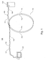
Figure 1 shows adevice 100, e.g. a reader or an RFID-tag reader, for communicating with RFID-tags. Thedevice 100 comprises afirst antenna 110, asecond antenna 120 and a reader IC (controller) 130. Thefirst antenna 110 is formed as circular loop antenna comprising afirst loop 112 and asecond loop 114. Thesecond antenna 120 is formed as a rectangular loop antenna comprising three rectangular loops. Thereader IC 130 comprises a processing unit (not shown) and a memory unit (not shown) if necessary for controlling the operation of theantennas device 100 is implemented. Such an apparatus may e.g. be a white goods device, such as a washing machine, comprising a corresponding main controller. - The
first antenna 110 and thesecond antenna 120 are connected in series between two terminals of thereader IC 130. The interconnection of thefirst antenna 110, thesecond antenna 120 and thereader IC 130 is constituted by a first twisted pair ofwires 140 and a second twisted pair ofwires 150. More specifically,wire 151 connects one terminal of thereader IC 130 to an input terminal of the first antenna, andwire 141 connects an output terminal of thefirst antenna 110 to an input terminal of thesecond antenna 120. Further,wire 142 connects an output terminal of thesecond antenna 120 to a second terminal of thereader IC 130 viawire 152. Thewires first antenna 110 or constitute respective sections of one continuous wire. Thus, a current feed to thewire 151 will run though thefirst antenna 110, continue throughwire 141, then run through thesecond antenna 120, and finally run back to the reader IC throughwires - In operation of the
device 100, the reader IC repeatedly feeds a sequence of different polling signals to the series connectedfirst antenna 110 andsecond antenna 120. The sequence of polling signals is designed such as to include sufficient time between each polling signal for detecting a possible response from an RFID-tag. If a response is detected, the reader IC switches to a communication mode and performs corresponding data communication with the responding RFID-tag. After finalizing the data communication, the reader IC may return to feeding the sequence of polling signals. - Accordingly, the
device 100 is capable of performing data communication with RFID-tags that are positioned in the vicinity of thefirst antenna 110 or thesecond antenna 120 by asingle reader IC 130 without the need for antenna switches. - The
first antenna 110 may preferably be designed for arrangement at or around the door of a washing machine (through which door dirty laundry is to be filled into the machine). Thesecond antenna 120 may preferably be designed for arrangement at a side wall of the washing machine close to the drawer or container into which detergent and/or fabric softener is to be provided. Thereader IC 130 is preferably designed to communicate with a washing machine controller, thereby allowing the latter to process data read from RFID-tags which have reacted to polling signals from thefirst antenna 110 and thesecond antenna 120. - It is explicitly noted that the
device 100 is not limited to two antennas but may easily be expanded to include one or more further antennas connected in series with thefirst antenna 110 and thesecond antenna 120. -
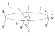
Figure 2 shows anantenna 200 for a device for communicating with RFID-tags, such as thedevice 100 shown inFigure 1 . Theantenna 200 is formed as amain loop 210 with branched-off sub-loops upper sub-loop 222 and thelower sub-loop 220 extend in parallel planes. Similarly, theleft sub-loop 230 and theright sub-loop 232 extend in parallel planes. The latter parallel planes are perpendicular to the parallel planes of theupper sub-loop 222 andlower sub-loop 220. Accordingly, the fields generated by theupper sub-loop 222 and thelower sub-loop 220 are perpendicular to the fields generated by theleft sub-loop 230 and theright sub-loop 232. In other words, the orientation of each of theleft sub-loop 230 and theright sub-loop 232 is perpendicular to the orientation of each of theupper sub-loop 222 and thelower sub-loop 220. Similarly, the orientations of all sub-loops 220, 222, 230 and 232 are perpendicular to the orientation of themain loop 210. - As indicated by
arrows left sub-loop 230 and in the left-most part of theright sub-loop 232 is the same. This is preferably achieved by forming theleft sub-loop 230 to comprise aslight opening 231 where it is branched-off from themain loop 210, i.e. by steeply bending the wire of theantenna 200 upwards at theopening 231. On the other hand, theright sub-loop 232 is formed by crossing the wire of theantenna 200 at thepoint 233. As a result, theleft sub-loop 230 and theright sub-loop 232 cooperate to produce a strong field in one direction. Similarly, thelower sub-loop 220 comprises aslight opening 221 whereas theupper sub-loop 222 comprises a crossing wire at thepoint 223. - As a result, the
antenna 200 produces a non-homogenous field and is accordingly capable of communicating with RFID-tags independently of the orientation of the RFID-tag relative to theantenna 200.
Claims (9)
- Device (100) for communicating with RFID-tags, the device (100) comprising
an antenna unit comprising a first antenna (110; 200) and a second antenna (120; 200), and
a controller (130) connected to the antenna unit,
wherein the controller (130) is adapted to sequentially feed different polling signals to the antenna unit such that corresponding signals are simultaneously radiated by each of the first antenna (110; 200) and second antenna (120; 200),
characterized in that at least one of the first antenna (110; 200) and the second antenna (120; 200) comprises a first sub-antenna (210, 220, 222, 230, 232) and a second sub-antenna (210, 220, 222, 230, 232), the first sub-antenna (210, 220, 222, 230, 232) and the second sub-antenna (210, 220, 222, 230, 232) being connected in series and having different orientations. - Device (100) according to claim 1, wherein
the first antenna (110; 200) and the second antenna (120; 200) are connected in series. - Device (100) according to claim 1 or 2, wherein
the first antenna (110; 200) and the second antenna (120; 200) are displaced relative to each other. - Device (100) according to claim 3, wherein
the first antenna (110; 200) and the second antenna (120; 200) are connected by a twisted pair of wires (140, 150). - Device (100) according to claim 1, wherein
the first sub-antenna (210, 220, 222, 230, 232) comprises a loop extending in a first plane, and
the second sub-antenna (210, 220, 222, 230, 232) comprises a loop extending in a plane perpendicular to the first plane. - Device according to any of claims 1 to 5, wherein
the controller (130) is further adapted to
detect a response to a polling signal from a responding RFID tag, and
when a response to a polling signal is received, perform communication with the responding RFID tag. - Device according to any of claims 1 to 6, wherein
each of the different polling signals corresponds to one of a plurality of RFID communication protocols. - Device according to claim 7, wherein the plurality of RFID protocols comprises
ISO/IEC 14443 p3a,
ISO/IEC 14443 p3b,
ISO/IEC 14443 p4,
ISO/IEC 14443 p4a,
ISO/IEC 15693,
ISO/IEC 18092, and/or
"FeliCa". - A home appliance comprising
a device (100) according to any of claims 1 to 8.
Priority Applications (3)
| Application Number | Priority Date | Filing Date | Title |
|---|---|---|---|
| EP12160850.9A EP2642423B1 (en) | 2012-03-22 | 2012-03-22 | Combined multifunctional RFID communication device |
| CN201310038592.1A CN103324900B (en) | 2012-03-22 | 2013-01-31 | Multifunctional assembled RFID communication device |
| US13/846,748 US9633242B2 (en) | 2012-03-22 | 2013-03-18 | Combined multifunctional RFID communication device |
Applications Claiming Priority (1)
| Application Number | Priority Date | Filing Date | Title |
|---|---|---|---|
| EP12160850.9A EP2642423B1 (en) | 2012-03-22 | 2012-03-22 | Combined multifunctional RFID communication device |
Publications (2)
| Publication Number | Publication Date |
|---|---|
| EP2642423A1 EP2642423A1 (en) | 2013-09-25 |
| EP2642423B1 true EP2642423B1 (en) | 2015-06-10 |
Family
ID=46021986
Family Applications (1)
| Application Number | Title | Priority Date | Filing Date |
|---|---|---|---|
| EP12160850.9A Not-in-force EP2642423B1 (en) | 2012-03-22 | 2012-03-22 | Combined multifunctional RFID communication device |
Country Status (3)
| Country | Link |
|---|---|
| US (1) | US9633242B2 (en) |
| EP (1) | EP2642423B1 (en) |
| CN (1) | CN103324900B (en) |
Families Citing this family (4)
| Publication number | Priority date | Publication date | Assignee | Title |
|---|---|---|---|---|
| US9124393B2 (en) | 2013-12-20 | 2015-09-01 | Nxp B.V. | End of communication detection |
| US20170241066A1 (en) * | 2014-11-02 | 2017-08-24 | Nicholas Caspers | Laundry appliance that identifies items not intended to be run through a washer or dryer cycle |
| US10056931B2 (en) * | 2016-02-17 | 2018-08-21 | Autotalks Ltd | Digital remote antennas operation |
| US10167916B2 (en) * | 2016-07-29 | 2019-01-01 | Trw Automotive U.S. Llc | Brake pad wear sensor |
Citations (2)
| Publication number | Priority date | Publication date | Assignee | Title |
|---|---|---|---|---|
| EP0496609A1 (en) * | 1991-01-23 | 1992-07-29 | Texas Instruments Holland B.V. | Interrogating station for objects to be identified |
| US20050242959A1 (en) * | 2004-04-28 | 2005-11-03 | Fuji Xerox Co., Ltd | IC tag provided with three-dimensional antenna and pallet provided with the IC tag |
Family Cites Families (27)
| Publication number | Priority date | Publication date | Assignee | Title |
|---|---|---|---|---|
| US4879570A (en) * | 1987-03-24 | 1989-11-07 | Nippon Antenna Co., Ltd. | Broadcasting wave reception antenna |
| CA1290450C (en) * | 1987-09-09 | 1991-10-08 | Thomas Tralman | Polarization selective surface for circular polarization |
| US5500651A (en) * | 1994-06-24 | 1996-03-19 | Texas Instruments Incorporated | System and method for reading multiple RF-ID transponders |
| US6686829B1 (en) * | 1998-01-19 | 2004-02-03 | Zih Corp. | Electronic identification system with forward error correction system |
| US7592898B1 (en) * | 1999-03-09 | 2009-09-22 | Keystone Technology Solutions, Llc | Wireless communication systems, interrogators and methods of communicating within a wireless communication system |
| WO2002032468A1 (en) * | 2000-10-13 | 2002-04-25 | Olympus Optical Co., Ltd. | Automatic cleaning and disinfecting device |
| US6703935B1 (en) * | 2001-05-14 | 2004-03-09 | Amerasia International Technology, Inc. | Antenna arrangement for RFID smart tags |
| RU2004124049A (en) | 2002-01-09 | 2005-03-27 | Мидвествако Корпорейшн (Us) | INTELLIGENT STATION WITH A SET OF RADIO FREQUENCY ANTENNAS, SYSTEM AND METHOD OF INVENTORY CONTROL WITH ITS USE |
| US20040046642A1 (en) * | 2002-09-05 | 2004-03-11 | Honeywell International Inc. | Protocol for addressing groups of RFID tags |
| JP2004227315A (en) * | 2003-01-23 | 2004-08-12 | Matsushita Electric Ind Co Ltd | Noncontact ic card reader/writer device |
| DE102004038685A1 (en) * | 2004-08-10 | 2006-02-23 | Tkm Telekommunikation Und Elektronik Gmbh | Arrangement for the identification and localization of objects |
| US7375616B2 (en) * | 2004-09-08 | 2008-05-20 | Nokia Corporation | Electronic near field communication enabled multifunctional device and method of its operation |
| US20060267730A1 (en) | 2005-05-27 | 2006-11-30 | Psc Scanning, Inc. | Apparatus and method for saving power in RFID readers |
| US7589601B2 (en) | 2005-09-07 | 2009-09-15 | Maury Microwave, Inc. | Impedance tuner systems and probes |
| KR20070091390A (en) | 2006-03-06 | 2007-09-11 | 엘지이노텍 주식회사 | Refrigerator system using radio frequency identification |
| US7605705B2 (en) * | 2006-08-22 | 2009-10-20 | International Business Machines Corporation | Method and apparatus for tracking or identifying items in a set |
| US8570172B2 (en) * | 2006-09-08 | 2013-10-29 | Intelleflex Corporation | RFID system with distributed transmitters |
| US20080283585A1 (en) * | 2006-12-03 | 2008-11-20 | Carol Peterman | Selective laundering systems and methods |
| KR20080075653A (en) | 2007-02-13 | 2008-08-19 | 권혁숙 | Rfid reader with multi antenna |
| US8063769B2 (en) * | 2007-03-30 | 2011-11-22 | Broadcom Corporation | Dual band antenna and methods for use therewith |
| US7973645B1 (en) | 2007-05-25 | 2011-07-05 | Impinj, Inc. | RFID reader devices and methods thereof |
| KR20090020935A (en) | 2007-08-24 | 2009-02-27 | 엘지전자 주식회사 | Refrigerator and method of controlling the same |
| US20090102610A1 (en) * | 2007-10-22 | 2009-04-23 | The Stanley Works | Rfid antenna selection system and method |
| JP5106237B2 (en) * | 2008-05-02 | 2012-12-26 | オリンパス株式会社 | Wireless power supply system |
| US8446256B2 (en) * | 2008-05-19 | 2013-05-21 | Sirit Technologies Inc. | Multiplexing radio frequency signals |
| US8872662B2 (en) * | 2009-02-12 | 2014-10-28 | Haldor Advanced Technologies Ltd. | Antenna, apparatus and method for identifying and tracking multiple items |
| US8797146B2 (en) * | 2010-04-27 | 2014-08-05 | Apple Inc. | Autonomous battery-free microwave frequency communication system |
-
2012
- 2012-03-22 EP EP12160850.9A patent/EP2642423B1/en not_active Not-in-force
-
2013
- 2013-01-31 CN CN201310038592.1A patent/CN103324900B/en not_active Expired - Fee Related
- 2013-03-18 US US13/846,748 patent/US9633242B2/en not_active Expired - Fee Related
Patent Citations (2)
| Publication number | Priority date | Publication date | Assignee | Title |
|---|---|---|---|---|
| EP0496609A1 (en) * | 1991-01-23 | 1992-07-29 | Texas Instruments Holland B.V. | Interrogating station for objects to be identified |
| US20050242959A1 (en) * | 2004-04-28 | 2005-11-03 | Fuji Xerox Co., Ltd | IC tag provided with three-dimensional antenna and pallet provided with the IC tag |
Also Published As
| Publication number | Publication date |
|---|---|
| US9633242B2 (en) | 2017-04-25 |
| EP2642423A1 (en) | 2013-09-25 |
| CN103324900A (en) | 2013-09-25 |
| CN103324900B (en) | 2016-03-02 |
| US20130249675A1 (en) | 2013-09-26 |
Similar Documents
| Publication | Publication Date | Title |
|---|---|---|
| US10387697B2 (en) | Pairing method for wireless scanner via RFID | |
| US10049238B2 (en) | Encoded information reading terminal with item locate functionality | |
| CN101425148B (en) | Multi-mode rfid tag and its operation method | |
| EP2642423B1 (en) | Combined multifunctional RFID communication device | |
| CN103218585B (en) | RFID protocol with nonreciprocal variable | |
| EP4028934A1 (en) | Multipurpose rfid transponder and a system for reading it | |
| WO2007025061A2 (en) | Coherent multichip rfid tag and method and appartus for creating such coherence | |
| KR20070074016A (en) | Handheld device having both barcode reader and rfid reading function, and information management system using the same | |
| KR20080106111A (en) | Multi-mode rfid reader architecture | |
| EP3545469B1 (en) | Method and apparatus for passive remote control | |
| EP4002195A1 (en) | Rfid reader with configuration for either an internal antenna or external antenna | |
| KR20190054437A (en) | Apparatus and method for avoiding cross reading of rfid using visible light recognition | |
| US20220190859A1 (en) | Nfc device unlocking method | |
| WO2012159577A1 (en) | Radio frequency identification reader pad | |
| WO2020128424A1 (en) | An rfid system with improved signal transmission characteristics | |
| KR101124314B1 (en) | Device for Radio Frequency Identification |
Legal Events
| Date | Code | Title | Description |
|---|---|---|---|
| PUAI | Public reference made under article 153(3) epc to a published international application that has entered the european phase |
Free format text: ORIGINAL CODE: 0009012 |
|
| AK | Designated contracting states |
Kind code of ref document: A1 Designated state(s): AL AT BE BG CH CY CZ DE DK EE ES FI FR GB GR HR HU IE IS IT LI LT LU LV MC MK MT NL NO PL PT RO RS SE SI SK SM TR |
|
| AX | Request for extension of the european patent |
Extension state: BA ME |
|
| 17P | Request for examination filed |
Effective date: 20131031 |
|
| 17Q | First examination report despatched |
Effective date: 20131202 |
|
| RBV | Designated contracting states (corrected) |
Designated state(s): AL AT BE BG CH CY CZ DE DK EE ES FI FR GB GR HR HU IE IS IT LI LT LU LV MC MK MT NL NO PL PT RO RS SE SI SK SM TR |
|
| GRAP | Despatch of communication of intention to grant a patent |
Free format text: ORIGINAL CODE: EPIDOSNIGR1 |
|
| INTG | Intention to grant announced |
Effective date: 20150122 |
|
| GRAS | Grant fee paid |
Free format text: ORIGINAL CODE: EPIDOSNIGR3 |
|
| GRAA | (expected) grant |
Free format text: ORIGINAL CODE: 0009210 |
|
| AK | Designated contracting states |
Kind code of ref document: B1 Designated state(s): AL AT BE BG CH CY CZ DE DK EE ES FI FR GB GR HR HU IE IS IT LI LT LU LV MC MK MT NL NO PL PT RO RS SE SI SK SM TR |
|
| REG | Reference to a national code |
Ref country code: GB Ref legal event code: FG4D |
|
| REG | Reference to a national code |
Ref country code: CH Ref legal event code: EP |
|
| REG | Reference to a national code |
Ref country code: AT Ref legal event code: REF Ref document number: 731173 Country of ref document: AT Kind code of ref document: T Effective date: 20150715 |
|
| REG | Reference to a national code |
Ref country code: DE Ref legal event code: R096 Ref document number: 602012007831 Country of ref document: DE |
|
| REG | Reference to a national code |
Ref country code: IE Ref legal event code: FG4D |
|
| PG25 | Lapsed in a contracting state [announced via postgrant information from national office to epo] |
Ref country code: ES Free format text: LAPSE BECAUSE OF FAILURE TO SUBMIT A TRANSLATION OF THE DESCRIPTION OR TO PAY THE FEE WITHIN THE PRESCRIBED TIME-LIMIT Effective date: 20150610 Ref country code: LT Free format text: LAPSE BECAUSE OF FAILURE TO SUBMIT A TRANSLATION OF THE DESCRIPTION OR TO PAY THE FEE WITHIN THE PRESCRIBED TIME-LIMIT Effective date: 20150610 Ref country code: FI Free format text: LAPSE BECAUSE OF FAILURE TO SUBMIT A TRANSLATION OF THE DESCRIPTION OR TO PAY THE FEE WITHIN THE PRESCRIBED TIME-LIMIT Effective date: 20150610 Ref country code: NO Free format text: LAPSE BECAUSE OF FAILURE TO SUBMIT A TRANSLATION OF THE DESCRIPTION OR TO PAY THE FEE WITHIN THE PRESCRIBED TIME-LIMIT Effective date: 20150910 |
|
| REG | Reference to a national code |
Ref country code: AT Ref legal event code: MK05 Ref document number: 731173 Country of ref document: AT Kind code of ref document: T Effective date: 20150610 |
|
| REG | Reference to a national code |
Ref country code: NL Ref legal event code: MP Effective date: 20150610 |
|
| PG25 | Lapsed in a contracting state [announced via postgrant information from national office to epo] |
Ref country code: RS Free format text: LAPSE BECAUSE OF FAILURE TO SUBMIT A TRANSLATION OF THE DESCRIPTION OR TO PAY THE FEE WITHIN THE PRESCRIBED TIME-LIMIT Effective date: 20150610 Ref country code: BG Free format text: LAPSE BECAUSE OF FAILURE TO SUBMIT A TRANSLATION OF THE DESCRIPTION OR TO PAY THE FEE WITHIN THE PRESCRIBED TIME-LIMIT Effective date: 20150910 Ref country code: LV Free format text: LAPSE BECAUSE OF FAILURE TO SUBMIT A TRANSLATION OF THE DESCRIPTION OR TO PAY THE FEE WITHIN THE PRESCRIBED TIME-LIMIT Effective date: 20150610 Ref country code: GR Free format text: LAPSE BECAUSE OF FAILURE TO SUBMIT A TRANSLATION OF THE DESCRIPTION OR TO PAY THE FEE WITHIN THE PRESCRIBED TIME-LIMIT Effective date: 20150911 |
|
| PG25 | Lapsed in a contracting state [announced via postgrant information from national office to epo] |
Ref country code: EE Free format text: LAPSE BECAUSE OF FAILURE TO SUBMIT A TRANSLATION OF THE DESCRIPTION OR TO PAY THE FEE WITHIN THE PRESCRIBED TIME-LIMIT Effective date: 20150610 |
|
| REG | Reference to a national code |
Ref country code: FR Ref legal event code: PLFP Year of fee payment: 5 |
|
| PG25 | Lapsed in a contracting state [announced via postgrant information from national office to epo] |
Ref country code: RO Free format text: LAPSE BECAUSE OF NON-PAYMENT OF DUE FEES Effective date: 20150610 Ref country code: IS Free format text: LAPSE BECAUSE OF FAILURE TO SUBMIT A TRANSLATION OF THE DESCRIPTION OR TO PAY THE FEE WITHIN THE PRESCRIBED TIME-LIMIT Effective date: 20151010 Ref country code: CZ Free format text: LAPSE BECAUSE OF FAILURE TO SUBMIT A TRANSLATION OF THE DESCRIPTION OR TO PAY THE FEE WITHIN THE PRESCRIBED TIME-LIMIT Effective date: 20150610 Ref country code: PT Free format text: LAPSE BECAUSE OF FAILURE TO SUBMIT A TRANSLATION OF THE DESCRIPTION OR TO PAY THE FEE WITHIN THE PRESCRIBED TIME-LIMIT Effective date: 20151012 Ref country code: SK Free format text: LAPSE BECAUSE OF FAILURE TO SUBMIT A TRANSLATION OF THE DESCRIPTION OR TO PAY THE FEE WITHIN THE PRESCRIBED TIME-LIMIT Effective date: 20150610 Ref country code: AT Free format text: LAPSE BECAUSE OF FAILURE TO SUBMIT A TRANSLATION OF THE DESCRIPTION OR TO PAY THE FEE WITHIN THE PRESCRIBED TIME-LIMIT Effective date: 20150610 Ref country code: PL Free format text: LAPSE BECAUSE OF FAILURE TO SUBMIT A TRANSLATION OF THE DESCRIPTION OR TO PAY THE FEE WITHIN THE PRESCRIBED TIME-LIMIT Effective date: 20150610 |
|
| REG | Reference to a national code |
Ref country code: DE Ref legal event code: R097 Ref document number: 602012007831 Country of ref document: DE |
|
| PLBE | No opposition filed within time limit |
Free format text: ORIGINAL CODE: 0009261 |
|
| STAA | Information on the status of an ep patent application or granted ep patent |
Free format text: STATUS: NO OPPOSITION FILED WITHIN TIME LIMIT |
|
| PG25 | Lapsed in a contracting state [announced via postgrant information from national office to epo] |
Ref country code: IT Free format text: LAPSE BECAUSE OF FAILURE TO SUBMIT A TRANSLATION OF THE DESCRIPTION OR TO PAY THE FEE WITHIN THE PRESCRIBED TIME-LIMIT Effective date: 20150610 Ref country code: DK Free format text: LAPSE BECAUSE OF FAILURE TO SUBMIT A TRANSLATION OF THE DESCRIPTION OR TO PAY THE FEE WITHIN THE PRESCRIBED TIME-LIMIT Effective date: 20150610 |
|
| 26N | No opposition filed |
Effective date: 20160311 |
|
| PG25 | Lapsed in a contracting state [announced via postgrant information from national office to epo] |
Ref country code: SI Free format text: LAPSE BECAUSE OF FAILURE TO SUBMIT A TRANSLATION OF THE DESCRIPTION OR TO PAY THE FEE WITHIN THE PRESCRIBED TIME-LIMIT Effective date: 20150610 |
|
| PG25 | Lapsed in a contracting state [announced via postgrant information from national office to epo] |
Ref country code: BE Free format text: LAPSE BECAUSE OF NON-PAYMENT OF DUE FEES Effective date: 20160331 |
|
| PG25 | Lapsed in a contracting state [announced via postgrant information from national office to epo] |
Ref country code: LU Free format text: LAPSE BECAUSE OF FAILURE TO SUBMIT A TRANSLATION OF THE DESCRIPTION OR TO PAY THE FEE WITHIN THE PRESCRIBED TIME-LIMIT Effective date: 20160322 Ref country code: MC Free format text: LAPSE BECAUSE OF FAILURE TO SUBMIT A TRANSLATION OF THE DESCRIPTION OR TO PAY THE FEE WITHIN THE PRESCRIBED TIME-LIMIT Effective date: 20150610 |
|
| REG | Reference to a national code |
Ref country code: CH Ref legal event code: PL |
|
| REG | Reference to a national code |
Ref country code: IE Ref legal event code: MM4A |
|
| PG25 | Lapsed in a contracting state [announced via postgrant information from national office to epo] |
Ref country code: BE Free format text: LAPSE BECAUSE OF FAILURE TO SUBMIT A TRANSLATION OF THE DESCRIPTION OR TO PAY THE FEE WITHIN THE PRESCRIBED TIME-LIMIT Effective date: 20150610 |
|
| PG25 | Lapsed in a contracting state [announced via postgrant information from national office to epo] |
Ref country code: IE Free format text: LAPSE BECAUSE OF NON-PAYMENT OF DUE FEES Effective date: 20160322 Ref country code: CH Free format text: LAPSE BECAUSE OF NON-PAYMENT OF DUE FEES Effective date: 20160331 Ref country code: LI Free format text: LAPSE BECAUSE OF NON-PAYMENT OF DUE FEES Effective date: 20160331 |
|
| REG | Reference to a national code |
Ref country code: FR Ref legal event code: PLFP Year of fee payment: 6 |
|
| PG25 | Lapsed in a contracting state [announced via postgrant information from national office to epo] |
Ref country code: NL Free format text: LAPSE BECAUSE OF FAILURE TO SUBMIT A TRANSLATION OF THE DESCRIPTION OR TO PAY THE FEE WITHIN THE PRESCRIBED TIME-LIMIT Effective date: 20150610 Ref country code: SE Free format text: LAPSE BECAUSE OF FAILURE TO SUBMIT A TRANSLATION OF THE DESCRIPTION OR TO PAY THE FEE WITHIN THE PRESCRIBED TIME-LIMIT Effective date: 20150610 |
|
| PG25 | Lapsed in a contracting state [announced via postgrant information from national office to epo] |
Ref country code: MT Free format text: LAPSE BECAUSE OF FAILURE TO SUBMIT A TRANSLATION OF THE DESCRIPTION OR TO PAY THE FEE WITHIN THE PRESCRIBED TIME-LIMIT Effective date: 20150610 |
|
| REG | Reference to a national code |
Ref country code: FR Ref legal event code: PLFP Year of fee payment: 7 |
|
| PG25 | Lapsed in a contracting state [announced via postgrant information from national office to epo] |
Ref country code: HU Free format text: LAPSE BECAUSE OF FAILURE TO SUBMIT A TRANSLATION OF THE DESCRIPTION OR TO PAY THE FEE WITHIN THE PRESCRIBED TIME-LIMIT; INVALID AB INITIO Effective date: 20120322 Ref country code: CY Free format text: LAPSE BECAUSE OF FAILURE TO SUBMIT A TRANSLATION OF THE DESCRIPTION OR TO PAY THE FEE WITHIN THE PRESCRIBED TIME-LIMIT Effective date: 20150610 Ref country code: SM Free format text: LAPSE BECAUSE OF FAILURE TO SUBMIT A TRANSLATION OF THE DESCRIPTION OR TO PAY THE FEE WITHIN THE PRESCRIBED TIME-LIMIT Effective date: 20150610 |
|
| PG25 | Lapsed in a contracting state [announced via postgrant information from national office to epo] |
Ref country code: MT Free format text: LAPSE BECAUSE OF FAILURE TO SUBMIT A TRANSLATION OF THE DESCRIPTION OR TO PAY THE FEE WITHIN THE PRESCRIBED TIME-LIMIT Effective date: 20160331 Ref country code: MK Free format text: LAPSE BECAUSE OF FAILURE TO SUBMIT A TRANSLATION OF THE DESCRIPTION OR TO PAY THE FEE WITHIN THE PRESCRIBED TIME-LIMIT Effective date: 20150610 Ref country code: HR Free format text: LAPSE BECAUSE OF FAILURE TO SUBMIT A TRANSLATION OF THE DESCRIPTION OR TO PAY THE FEE WITHIN THE PRESCRIBED TIME-LIMIT Effective date: 20150610 Ref country code: TR Free format text: LAPSE BECAUSE OF FAILURE TO SUBMIT A TRANSLATION OF THE DESCRIPTION OR TO PAY THE FEE WITHIN THE PRESCRIBED TIME-LIMIT Effective date: 20150610 |
|
| PG25 | Lapsed in a contracting state [announced via postgrant information from national office to epo] |
Ref country code: AL Free format text: LAPSE BECAUSE OF FAILURE TO SUBMIT A TRANSLATION OF THE DESCRIPTION OR TO PAY THE FEE WITHIN THE PRESCRIBED TIME-LIMIT Effective date: 20150610 |
|
| PGFP | Annual fee paid to national office [announced via postgrant information from national office to epo] |
Ref country code: GB Payment date: 20200221 Year of fee payment: 9 Ref country code: DE Payment date: 20200218 Year of fee payment: 9 |
|
| PGFP | Annual fee paid to national office [announced via postgrant information from national office to epo] |
Ref country code: FR Payment date: 20200220 Year of fee payment: 9 |
|
| REG | Reference to a national code |
Ref country code: DE Ref legal event code: R119 Ref document number: 602012007831 Country of ref document: DE |
|
| GBPC | Gb: european patent ceased through non-payment of renewal fee |
Effective date: 20210322 |
|
| PG25 | Lapsed in a contracting state [announced via postgrant information from national office to epo] |
Ref country code: FR Free format text: LAPSE BECAUSE OF NON-PAYMENT OF DUE FEES Effective date: 20210331 Ref country code: GB Free format text: LAPSE BECAUSE OF NON-PAYMENT OF DUE FEES Effective date: 20210322 Ref country code: DE Free format text: LAPSE BECAUSE OF NON-PAYMENT OF DUE FEES Effective date: 20211001 |