EP2642420B1 - Ambulatory medical device with electrical isolation from connected peripheral device - Google Patents
Ambulatory medical device with electrical isolation from connected peripheral device Download PDFInfo
- Publication number
- EP2642420B1 EP2642420B1 EP13170296.1A EP13170296A EP2642420B1 EP 2642420 B1 EP2642420 B1 EP 2642420B1 EP 13170296 A EP13170296 A EP 13170296A EP 2642420 B1 EP2642420 B1 EP 2642420B1
- Authority
- EP
- European Patent Office
- Prior art keywords
- circuitry
- isolator
- gmr
- medical device
- transceiver
- Prior art date
- Legal status (The legal status is an assumption and is not a legal conclusion. Google has not performed a legal analysis and makes no representation as to the accuracy of the status listed.)
- Not-in-force
Links
Images


Classifications
-
- A—HUMAN NECESSITIES
- A61—MEDICAL OR VETERINARY SCIENCE; HYGIENE
- A61M—DEVICES FOR INTRODUCING MEDIA INTO, OR ONTO, THE BODY; DEVICES FOR TRANSDUCING BODY MEDIA OR FOR TAKING MEDIA FROM THE BODY; DEVICES FOR PRODUCING OR ENDING SLEEP OR STUPOR
- A61M5/00—Devices for bringing media into the body in a subcutaneous, intra-vascular or intramuscular way; Accessories therefor, e.g. filling or cleaning devices, arm-rests
- A61M5/14—Infusion devices, e.g. infusing by gravity; Blood infusion; Accessories therefor
- A61M5/142—Pressure infusion, e.g. using pumps
-
- A—HUMAN NECESSITIES
- A61—MEDICAL OR VETERINARY SCIENCE; HYGIENE
- A61M—DEVICES FOR INTRODUCING MEDIA INTO, OR ONTO, THE BODY; DEVICES FOR TRANSDUCING BODY MEDIA OR FOR TAKING MEDIA FROM THE BODY; DEVICES FOR PRODUCING OR ENDING SLEEP OR STUPOR
- A61M5/00—Devices for bringing media into the body in a subcutaneous, intra-vascular or intramuscular way; Accessories therefor, e.g. filling or cleaning devices, arm-rests
- A61M5/14—Infusion devices, e.g. infusing by gravity; Blood infusion; Accessories therefor
- A61M5/168—Means for controlling media flow to the body or for metering media to the body, e.g. drip meters, counters ; Monitoring media flow to the body
- A61M5/172—Means for controlling media flow to the body or for metering media to the body, e.g. drip meters, counters ; Monitoring media flow to the body electrical or electronic
-
- G—PHYSICS
- G01—MEASURING; TESTING
- G01R—MEASURING ELECTRIC VARIABLES; MEASURING MAGNETIC VARIABLES
- G01R33/00—Arrangements or instruments for measuring magnetic variables
- G01R33/02—Measuring direction or magnitude of magnetic fields or magnetic flux
- G01R33/06—Measuring direction or magnitude of magnetic fields or magnetic flux using galvano-magnetic devices
- G01R33/09—Magnetoresistive devices
- G01R33/091—Constructional adaptation of the sensor to specific applications
-
- A—HUMAN NECESSITIES
- A61—MEDICAL OR VETERINARY SCIENCE; HYGIENE
- A61M—DEVICES FOR INTRODUCING MEDIA INTO, OR ONTO, THE BODY; DEVICES FOR TRANSDUCING BODY MEDIA OR FOR TAKING MEDIA FROM THE BODY; DEVICES FOR PRODUCING OR ENDING SLEEP OR STUPOR
- A61M2205/00—General characteristics of the apparatus
- A61M2205/35—Communication
- A61M2205/3546—Range
- A61M2205/3561—Range local, e.g. within room or hospital
-
- A—HUMAN NECESSITIES
- A61—MEDICAL OR VETERINARY SCIENCE; HYGIENE
- A61M—DEVICES FOR INTRODUCING MEDIA INTO, OR ONTO, THE BODY; DEVICES FOR TRANSDUCING BODY MEDIA OR FOR TAKING MEDIA FROM THE BODY; DEVICES FOR PRODUCING OR ENDING SLEEP OR STUPOR
- A61M2209/00—Ancillary equipment
- A61M2209/02—Equipment for testing the apparatus
Definitions
- the present invention relates generally to improvements for ambulatory medical devices such as devices for introducing treatment material into a body by infusion. More particularly, the invention relates to an ambulatory medical device that is connected by a cable to a peripheral device.
- ElectroCardioGram ECG signals
- drug delivery devices In some circumstances, multiple devices are in conductive contact with the same patient at the same time.
- Electrical safety is perhaps of the greatest concern for those devices that are adapted to be placed in contact with intravenous fluids in the human body. This is because the human circulatory system primarily consists of water, which is highly conductive. Electrical safety is a particular concern for devices that are adapted to supply fluid to the human circulator system, because the delivered fluid creates a direct and highly conductive path for harmful currents to reach the human body.
- a peripheral device is a personal computer.
- Some medical devices include a data port that allows an electrical data connection to be made between the medical device and the peripheral device.
- a medical device may be may be adapted to communicate with a peripheral device using a passive connection or an active connection.
- a passive connection is one in which electrical signals are transmitted for purposes of communicating data only.
- active devices are those that allow power to be transferred from the peripheral device to the medical device. Examples of passive connections include: RS-232, IEEE 488, Medical Information Bus, Ethernet connection, telephone style connectors, or any other standard or non-standard connector. Examples of active connections include Universal Serial Bus (USB), FireWire, and Power over Ethernet (PoE) connections.
- USB Universal Serial Bus
- FireWire FireWire
- PoE Power over Ethernet
- the danger that exists as a result of the use of electronic devices that are in contact with a patient requires that the medical device be disconnected from contact with the patient in order to connect a peripheral device. This limits a physician or other user, because the removal of the device prevents capture of real-time data from the device while it is connected to the patient. Also, the removal of the device itself may be very cumbersome and time consuming, and may further expose the patient to risk (such as where a needle is removed).
- isolation typically takes the form of translating an electrical signal to some other medium, such as an optical signal, to avoid the transfer of electrical current, and thus the hazards associated with the use of such devices as discussed above.
- optical isolators Some examples of optical isolators are described in the following U.S. Patent documents: US Publ. Appl. No. 2005/0001179 to Gisler et al. , U.S. Patent No. 6,617,846 to Hayat-Dawoodi et al. , US Publ. Appl. No. 2004/0113498 to Kroenke , and U.S. Publ. Appl. No. 2006/0265540 to Mass et al.
- Optical isolators work by operating one or more light emitting elements (such as a light emitting diode) to transmit light in response to the contents of an electrical signal on one side of the medical device/peripheral device interface.
- Optical isolators are advantageous in that they provide low-cost and reliable isolation of an electrical signal.
- optical isolators are limited in that they are only capable of effectively isolating an electrical signal transmitted at relatively slower data rates. Therefore, a need exists to provide improved devices and methods providing for a more reliable, higher-speed electrical isolation of signals for use in ambulatory medical devices which utilize active peripheral interface connections.
- FIG. 1 illustrates generally one example of an electrical medical device 104 in contact with a patient 109 and adapted to be electrically connected to a peripheral device 102.
- medical device 104 may be connectable to a peripheral device via an active communication cable 103.
- medical device 104 may include housing 115. Housing 115 may be sized and configured to be ambulatory for patient 109.
- Medical device 104 may include communication circuitry 105, processor 106, and one or more medical treatment functions 107. Medical treatment functions 107 may include, for example, one or more sensors or one or more therapy delivery devices. The one or more therapy delivery devices may be adapted to deliver electrical therapy or drug therapy to patient 109.
- Medical device 104 also includes battery 112. Battery 112 provides electrical power to medical device 104 and has a battery ground.
- peripheral device 102 is any device capable of communicating with medical device 102.
- peripheral device 102 is a computer.
- Medical device 104 may be connected to patient 109 through connector 108.
- medical device 104 is adapted to measure, store, and/or communicate device specific or patient specific information to peripheral device 102.
- medical device 102 is adapted to receive and/or transmit data and/or commands from peripheral device 102.
- medical device 104 is electrically connected to peripheral device 102 through communication cable 103 such that peripheral device 102 can communicate with medical device 104.
- Medical device 104 may include one or more communication connectors 111.
- Communication connector(s) 111 may be configured to interface with communication cable 103 such that medical device 104 may be communicatively coupled to peripheral device 102.
- Communication circuitry 105 may be adapted to communicate with peripheral device 102 using communication cables 103 and communication connectors 111 such as: RS-232, IEEE 488, Universal Serial Bus (USB), Firewire, Medical Information Bus, Ethernet connection, telephone style connectors, or any other standard or non-standard connector.
- communication connector 111 and communication cable 103 support active communication, meaning they are adapted to supply power to medical device 104 through communication cable 103 in addition to providing electrical communication between peripheral device 102 and medical device 104. Examples of active communication cables include USB, Firewire, and powered Ethernet.
- Medical device 104 is powered by internal battery 112, and is designed to eliminate any risk of hazardous electrical current from being transferred to patient 109 when medical device 104 is connected to patient 109. However, when medical device 104 is also connected to peripheral device 102 through connector 103, the potential for hazardous electrical current to reach patient 109 exists.
- FIG. 1 provides a physician or other user the ability to communicate with medical device 104 through electrical connector 103
- electrical hazard concerns require that medical device 104 be disconnected from patient 109 in order to connect medical device 104 to peripheral device 102 and communicate with peripheral device 102.
- This is limiting because a physician or other user is unable to acquire real-time measurements of a patient's conditions or conditions of medical device 104 while medical device 104 is in contact with patient 109.
- medical device 104 must be disconnected and reconnected to patient 109. This may cause injury to patient 109 or may be time consuming or cumbersome.
- an already successful procedure may need to be re-performed.
- Electrical hazard concerns are significantly important when medical device 104 is placed in fluid contact with patient's 109 circulatory system. This is because a fluid conduit is configured to extend between medical device 104 and patient 109.
- communication transfer speeds when using communication cable 103 may not be able to sustain high data transfer rates in accordance with current data transfer standards for many of the communications protocols.
- medical device 104 is provided with conventional optical isolation circuitry connected to a USB 2.0 active communication cable, data transfer cannot be sustained at the data transfer rates of up to 12 Mb/second which the USB 2.0 active communication cable would otherwise support.
- FIG. 2 illustrates generally one embodiment of a medical device 204 and peripheral device 202 according to the subject matter disclosed herein.
- the embodiment illustrated in FIG. 2 is similar to the example of FIG. 1 , except medical device 204 further includes isolation circuitry 210.
- isolation circuitry 210 is adapted to transmit signals between medical device 204 and peripheral device 202 without transferring any electrical current to medical device 204 that could be potentially harmful to patient 209.
- FIG. 2 is advantageous, because due to isolation circuitry 210, medical device 204 may be electrically connected to peripheral device 202 and remain connected to patient 209 without a risk of harmful electrical currents. Therefore, an electrical connection between medical device 204 and patient 209 does not need to be broken by removing connector 208 from contact with patient 209 to eliminate any electrical hazard concerns.
- medical device 104 may communicate with peripheral device 202 without re-performing procedures to connect medical device 204 to patient 209.
- peripheral device 202 may communicate with medical device 204 while medical device 204 is connected to patient 209.
- FIG. 3 illustrates generally one embodiment of isolation circuitry 301 according to the subject matter disclosed herein.
- medical device 303 is adapted to communicate with peripheral device 302 using an active communication cable as discussed with respect to FIG. 1 above.
- medical device includes first isolation circuitry 313 and second isolation circuitry 312.
- first isolation circuitry 313 includes isolation transceivers 304 and 305.
- first isolation circuitry 313 further includes control circuitry having a communication port connected to isolation transceivers 304 and 305.
- second isolation circuitry 312 includes isolation transceivers 310 and 311. In one embodiment, second isolation circuitry 312 includes control circuitry electrically coupled to isolation transceivers 310 and 311.
- signals transferred between medical device 303 and peripheral device 302 are electrically isolated by isolation transceivers 304, 310 and 305, 311.
- communication lines 309 are split into data lines 307 and status lines 308.
- Data lines 307 may communicate data between medical device 303 and peripheral device 302.
- Status lines 308 may communicate a control signal such as information regarding a status of data transmission or information regarding a status of medical device 303 or peripheral device 302 related to data transmissions.
- data lines 307 communicate larger amounts of data, or more bits of information, than status lines 308.
- isolation components 304, 305, 310, and 311 are adapted to create a non-electrical signal indicative of an electrical signal on communication lines 309 at a first side of interface 306, and create an electrical signal indicative of the non-electrical signal at a second side of interface 306.
- data may be transferred between peripheral device 302 and medical device 303 without any potentially hazardous electrical currents traversing interface 306.
- data lines 307 are electrically isolated by Giant Magneto-Resistive Isolator (GMR isolator) transceivers 310 and 304.
- GMR isolator transceivers 310 and 304 achieve electrical isolation by changing an electrical resistance at one side of interface 306 in response to a changing magnetic field indicative of an electrical signal at the other side of interface 306.
- GMR isolator transceiver 310 is adapted to receive an electrical signal from peripheral device 302, and initiate or adjust a magnetic field in response to the electrical signal.
- GMR isolator transceiver 304 is adapted to detect the magnetic field, and create an electrical signal based at least in part on the detected magnetic field.
- GMR isolator transceiver 304 is adapted to receive an electrical signal from medical device 303, and initiate or adjust a magnetic field in response to the electrical signal.
- GMR isolator transceiver 310 is adapted to detect the magnetic field, and create an electrical signal based at least in part on the detected magnetic field.
- the present invention has recognized that a GMR isolator can be advantageous because the GMR isolator can isolate an electrical signal transferred at relatively fast data rates, particularly rates up to and in excess of 12 Mb/sec.
- a GMR isolator is also disadvantageous because in order to accurately transmit isolated data an initial state of the GMR isolator must be known such that the GMR isolator can be reset to or maintained in a known state when a communication is expected.
- the present invention recognizes and addresses these limitations in the various embodiments as described herein.
- status lines 307 are electrically isolated by isolator transceivers 311 and 305.
- isolator transceiver 311 is adapted to receive an electrical control signal, and communicate that control signal in an electrically isolated manner.
- isolator transceiver 305 is adapted to sense the communicated signal, and create an electrical control signal at the medical device 303 side of interface 306.
- isolator transceiver 305 is adapted to receive an electrical control signal, and communicate that control signal in an electrically isolated manner.
- isolator transceiver 311 is adapted to sense the communicated signal, and create an electrical control signal at the peripheral device 302 side of interface 306.
- GMR isolator transceivers 310 and 304 are used to provide electrical isolation for signals transferred over data lines 307
- control signal isolator transceivers 311 and 305 are used to provide electrical isolation for signals transferred over status lines 308.
- larger amounts of data and faster data rates are required for data line 307 communications.
- smaller amounts of signal transitions and slower transition rates may be required of status line 308 communications.
- first isolation circuitry 313 is housed within housing 215 and is electrically connected to a ground of battery 212.
- first isolation circuitry includes first isolator transceiver 305.
- First isolator transceiver 305 may be adapted to communicate at least one control signal.
- first isolation circuitry 313 includes first GMR transceiver 304.
- First GMR transceiver 304 may be adapted to communicate at least one electrical data signal.
- first isolation circuitry 313 further includes a control circuit having a communication port connected to the first isolator transceiver 305 and the first GMR transceiver 304 to communicate the at least one control signal and the at least one data signal to and from the control circuitry.
- second isolation circuitry 312 includes second isolator transceiver 311.
- second isolator transceiver 311 is coupled to first isolator transceiver 311 and is adapted to communicate at least one control signal.
- second isolation circuitry 312 includes second GMR transceiver 310.
- second GMR transceiver 310 is magnetically coupled to first GMR transceiver 304.
- Second GMR transceiver 310 may be adapted to communicate at least one data signal.
- second isolation circuitry 312 includes communication circuitry electrically coupled to communication connector 211, second GMR transceiver 310, and second isolator transceiver 311.
- the communication circuitry is adapted to communicate at least one data signal to and from active communication cable 203.
- control isolator transceivers 311 and 305 provide control signal(s) indicative of a transmission state of data with respect to data lines 307.
- GMR isolator transceivers 310 and 304 may be reset in response to the control signals.
- the control signal(s) are a single bit transmitted through isolator transceivers 311 and 305.
- the control signal(s) are multiple bits transmitted through isolator transceivers 311 and 305.
- the control signals indicate that the USB cable is connected and that GMR transceivers should prepared to communicate data.
- GMR isolator transceivers 310 and 304 and optical isolator transceivers 311 and 305 as discussed with respect to FIG. 3 is advantageous, because due to the control signal provided by isolator transceivers 311 and 305 over status lines 308, GMR isolator 304 may be reset. Therefore, electrical isolator 301 is able to transmit electrically isolated data at faster data rates without the inaccuracy typically associated with GMR isolators.
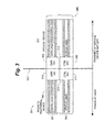
- FIG. 4 illustrates generally a flow chart diagram of one embodiment of a method of signal isolation according to the subject matter described herein.
- electrical isolation circuitry 301 is adapted to electrically isolate at least one signal transferred between peripheral device 302 and medical device 303.
- the signal may be communicated from peripheral device 302 to medical device 303 across interface 306.
- the signal may be communicated from medical device 303 to peripheral device 302 across interface 306.
- an indication of transmission status is received.
- the indication of transmission status is received through isolator transceivers 311 and 305.
- GMR isolator transceiver 310 or 304 is prepared to receive data.
- preparing the GMR isolator transceiver 310 or 304 to receive data includes modifying a state of GMR isolator transceiver 310 or 304.
- preparing the GMR isolator transceiver 310 or 304 to receive data includes maintaining a state of GMR isolator transceiver 310 or 304.
- At 403 at least one data bit is communicated across GMR isolator transceivers 310 and 304.
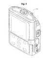
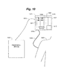
- FIG. 5 illustrates generally an infusion pump device 501 as the ambulatory medical device according to the subject matter disclosed herein.
- Infusion pump device 501 is adapted to be connected to a patient circulatory system.
- Infusion pump device 501 is further adapted to deliver drug therapy to a patient. Drug delivery may occur on a continuous or discreet basis.
- the ambulatory medical device may provide dialysis, gene therapy, diabetes treatments or any number of other similar medical treatments where continuous and/or periodic supply of a liquid between the patient and a medical device is part of the medical therapy.
- the ambulatory nature of the medical device 501 in accordance with the present invention relates to the ability to have the device carried by or mobile with the patient, for example, on a rolling stand, where the medical device is powered, at least in part, by some form of battery or stored energy power supply that is either housed within or carried along with the housing of the medical device.
- the medical device is powered, at least in part, by some form of battery or stored energy power supply that is either housed within or carried along with the housing of the medical device.
- the infusion pump device is provided with a supply of a liquid-medicament, either in the form of a cassette that is loaded and/or locked within the housing of the infusion pump device, or in the form of a container or bag carried external to the infusion pump device, or even as a separate liquid bag hung, for example, on a rolling medical hanger and connected by inlet tubes to the infusion pump device.
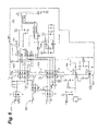
- FIG. 6 illustrates generally a circuit diagram of one embodiment of electrically isolated infusion pump circuitry according to the subject matter disclosed herein.
- USB transceiver 601 is adapted to receive and transmit communications.
- USB transceiver must be electrically isolated due to safety concerns.
- data signals to or from USB transceiver pass through GMR isolator transceivers 602.
- GMR isolator transceivers are adapted to transmit a signal without any electrical current transfer.
- the electrical circuit illustrated in FIG. 6 further includes optical isolator transceivers 603.
- optical isolator transceivers 503 are adapted to transmit signals indicative of a transmission state of USB transceiver 601 and/or the transmitting portion of GMR transceivers 602.
- the receiving portions of GMR transceivers 602 are adapted to be reset in response to the optical signals indicative of a transmission state.
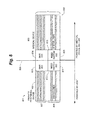
- FIG. 7 is a block diagram illustrating generally one embodiment of an isolator including optical isolators according to the subject matter disclosed herein.
- the embodiment illustrated in FIG. 7 is similar to the embodiment illustrated in FIG. 3 , except control isolation transceivers 311 and 305 are optical isolation transceivers.
- status lines 707 are electrically isolated by optical isolator transceivers 711 and 705.
- Optical isolators are advantageous in that they provide accurate electrical signal isolation.
- optical isolator transceiver 711 is adapted to receive an electrical control signal, and initiate or adjust an optical signal in response to the control signal.
- optical isolator transceiver 705 is adapted to detect the optical signal, and create an electrical control signal at the medical device 703 side of interface 706.
- optical isolator transceiver 705 is adapted to receive an electrical control signal, and initiate or adjust an optical signal in response to the electrical control signal.
- optical isolator transceiver 711 is adapted to detect the optical signal, and create an electrical control signal at the peripheral device 702 side of interface 706.
- control signal received by optical isolator transceivers 711 or 705 is converted to at least one electrical signal.
- a controller such as a microprocessor is adapted to receive the electrical signal and modify or maintain a state of GMR isolator transceivers 710 or 704 in response to the received electrical signal.
- the transmission state signal received by optical isolator transceivers 711 or 705 is not converted to an electrical signal.
- the at least one optical controller is adapted to receive the optical control signal and modify or maintain a state of GMR isolator transceivers 710 or 704 in response to the received optical signal.
- FIG. 8 is a block diagram illustrating generally one embodiment of an isolator that includes a magnetic reed switch according to the subject matter disclosed herein.
- the embodiment illustrated in FIG. 8 is similar to the embodiment illustrated in FIG. 3 , except control isolation transceivers 811 and 805 are reed switch isolation transceivers.
- a reed switch is an electrical switch operated by an applied magnetic field.
- a reed switch contains two magnetizable and electrically conductive metal reeds which have end portions separated by a small gap when the switch is open.
- an applied magnetic field causes the conductive metal reeds to pull together, thus completing an electrical circuit and allowing a current to flow.
- an applied magnetic field causes the conductive metal reeds to pull apart, thus causing current to stop flowing.
- reed switch isolator transceiver 811 is adapted to receive an electrical control signal, and initiate or adjust a magnetic field in response to the control signal.
- reed switch isolator transceiver 805 is adapted to detect the magnetic field, and create an electrical control signal at the medical device 803 side of interface 806.
- reed switch isolator transceiver 805 is adapted to receive an electrical control signal, and initiate or adjust a magnetic field in response to the electrical control signal.
- reed switch isolator transceiver 811 is adapted to detect the magnetic field signal, and create an electrical control signal at the peripheral device 802 side of interface 806.
- control signal received by reed switch isolator transceiver 811 or 805 is converted to at least one electrical signal.
- a controller such as a microprocessor is adapted to receive the electrical signal and modify or maintain a state of GMR isolator transceivers 810 or 804 in response to the received electrical signal.
- FIG. 9 is a block diagram illustrating generally one embodiment of an isolator that includes a capacitive coupling isolator according to the subject matter disclosed herein.
- the embodiment illustrated in FIG. 9 is similar to the embodiment illustrated in FIG. 3 , except control isolation transceivers 911 and 905 are capacitive coupling isolation transceivers.
- Capacitive coupling is the transfer of energy in an electrical circuit by means of a capacitance between circuit nodes.
- capacitive coupling has the effect of connecting two electrical circuits such that low frequency, or DC, components of a signal are removed from the signal.
- the voltage amplitude of a signal is greatly reduced while maintaining the higher frequency components of the signal.
- capacitors 911 and 905 are used to isolate control signals transferred over status lines 908.
- an electrical signal at capacitor 911 results in a related electrical signal at capacitor 905.
- the amplitude of the related electrical signal at capacitor 905 is greatly reduced compared to the electrical signal at capacitor 911.
- the electrical control signal may be transferred across interface 906 while greatly reducing the potential for electrical currents that may be harmful to a patient 209.
- a controller such as a microprocessor is adapted to receive the electrical control signal and modify or maintain a state of GMR isolator transceivers 910 or 904 in response to the received electrical signal.
- FIG. 10 is a block diagram illustrating generally one embodiment of a medical device that is adapted to be powered by an active communication cable according to the subject matter disclosed herein.
- the embodiment illustrated in FIG. 10 is similar to the embodiment illustrated in FIG. 2 , except medical device 1004 is adapted to be powered by active communication cable 1003.
- communication connector 1011 is adapted to provide a power connection to communication cable 1003.
- the power connection includes a positive terminal and a ground tenninal.
- communication connector 1011 includes a positive terminal and a ground terminal.
- communication connector 1011 and communication cable 1003 are sized, shaped, and/or positioned such that when communication connector 1011 is connected to communication cable 1003 the respective positive and negative terminals are electrically coupled.
- medical device 1004 includes a DC to DC transformer 1010.
- DC to DC transformer 1010 is a device adapted to transfer electrical energy from a first electrical circuit to a second electrical circuit through inductively coupled electrical conductors.
- a changing current at the first electrical circuit creates a changing magnetic field.
- the magnetic field induces a changing voltage in the second electrical circuit. If a load is added to the second electrical circuit a current is allowed to flow. Thus, electrical energy is transferred from the first electrical circuit to the second electrical circuit.
- DC to DC transformer 1010 is adapted to transfer a power signal originating at peripheral device 1002 to medical device 1004 through communicative cable 1003.
- DC to DC transformer 1010 is adapted to electrically isolate the power signal by providing a second ground terminal 1020 isolated from the ground terminal of communication connector 1011.
- harmful electrical currents are preventing from traversing medical device 1004 and reaching patient 1009.
- power supplied by DC to DC transformer 1010 is used to power components of medical device 1004 such as communication circuitry 1005, processor 1006, and one or more medical treatment functions 1007.
- DC to DC transformer 1010 is used to charge battery 1012.
- DC to DC transformer 1010 is adapted to modify a voltage level of power supplied to components of medical device 1004.
- FIG. 10 does not include a control isolation transceiver such as illustrated in FIG. 3 , it is to be understood that embodiments that include the supply of active power through DC to DC transformer 1010 and a separate control isolation transceiver are within the scope of the subject matter disclosed herein.
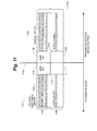
- FIG. 11 is a block diagram illustrating generally one embodiment of a medical device wherein power delivered by an active communication cable is used to transmit a control signal according to the subject matter disclosed herein.
- the embodiment illustrated in FIG. 11 is similar to the embodiment of FIG. 3 , except it includes DC to DC transformer 1111 and 1105.
- DC to DC transformer 1111 and 1105 is used to supply power to components of medical device 1004.
- DC to DC transformer 1111 and 1105 is further adapted to communicate at least one control signal across interface 1106.
- a transmission state must be known to set GMR isolator transceiver 1110 or 1104 to a known state.
- DC to DC transformer 1111 and 1105 are electrically coupled to at least one control circuit.
- the control circuit is adapted to detect whether power is being transferred across DC to DC transformer 1111 and 1105.
- the control circuit is able to determine whether communication cable 1003 is connected to communication connector 1011, and whether to set detecting portions of GMR isolator transceiver 1110 or 1104 to receive data transmissions.
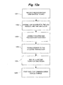
- FIG. 12a and FIG. 12b illustrates generally a flow chart diagram of embodiments of operating an isolated medical device according to the subject matter disclosed herein.
- the embodiments illustrated in FIG. 12a and FIG 12b and the associated discussion are directed to the circuit illustrated in FIG. 6 for exemplary purposes only.
- Some exemplary embodiments discussed herein are directed towards integrated circuit component Advanced Universal Serial Bus Transceiver part number ISP1104 available from Phillips Semiconductors. It is to be understood that these embodiments are presented for exemplary purposes only and alternate embodiments fall within the scope of the subject matter disclosed herein.
- FIG. 12a illustrates generally one embodiment of operating the subject matter disclosed herein when communication cable 203 is not connected to medical device 204.
- an indication that USB is not attached is received.
- receiving an indication that USB is not attached includes detecting that USBD_VDET signal has transitioned from a high state to a low state.
- receiving an indication that USB is not attached includes detecting that USBD_VDET signal is in a low state.
- USB interrupts, the USB module, and USB clock of USB transceiver 601 are disabled.
- the USB transceiver 601 analog front-end is disabled.
- disabling the USB transceiver 601 analog front-end includes setting USBD_AFE signal 605 to a low state.
- power to USB transceiver 601 is disabled.
- disabling power to the USB transceiver 601 includes setting USB_DISABLE signal 606 to a high state.
- a wait for shutdown function is performed.
- waiting for shutdown includes waiting at least 32k ticks for shutdown.
- the change in communication status event is posted.
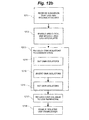
- FIG. 12a illustrates generally one embodiment of operating the subject matter disclosed herein when communication cable 203 is connected to medical device 204.
- an indication that communication cable 203 has been attached to medical device 204 is received.
- receiving an indication that USB is attached includes detecting that USBD_VDET signal 604 has transitioned from a low state to a high state.
- receiving an indication that USB is attached includes detecting that USBD_VDET signal 604 is in a high state.
- USB interrupts, the USB module of a processor, and USB clock of USB transceiver 601 are enabled.
- GMR isolators are set to a known state.
- setting the GMR isolators to a known state includes: 1) at 1214, setting GMR isolators; 2) at 1215, inverting the GMR isolators; 3) at 1216 setting the GMR isolators.
- setting the GMR isolators includes disabling the isolated USB transceiver 601 analog front end.
- enabling the isolated USB transceiver 601 analog front end includes setting USBD_AFE 605 to a low state.
- setting the GMR isolators 602 includes disabling the USB transceiver 601 output. In one embodiment, disabling the USB transceiver 601 output includes setting USB_OE 607 to a high state.
- inverting the GMR isolators 602 includes enabling the USB transceiver 601 analog front-end.
- enabling the USB transceiver 601 analog front-end includes setting USBD_AFE 605 to a high state.
- setting the GMR isolators 602 includes enabling the USB transceiver 601 output.
- disabling the USB transceiver 601 output includes setting USB_OE 607 to a low state.
- setting the GMR isolators 602 includes disabling the USB transceiver 601 analog front-end. In one embodiment, at 1216, enabling the USB transceiver 601 analog front-end includes setting USBD_AFE 605 to a low state. In one embodiment, at 1216, setting the GMR isolators 602 includes disabling the USB transceiver 601 output. In one embodiment, disabling the USB transceiver 601 output includes setting USB_OE 607 to a high state.
- control is returned to a peripheral device attached to medical device 204 through communication cable 203.
- returning control to the peripheral device includes returning control of USBD_AFE 605 and USB_OE 607 signals.
- the USB transceiver 601 is enabled. In one embodiment, enabling the USB transceiver 601 includes setting USB_DISABLE 606 to a low state.
Landscapes
- Health & Medical Sciences (AREA)
- Vascular Medicine (AREA)
- Engineering & Computer Science (AREA)
- Anesthesiology (AREA)
- Biomedical Technology (AREA)
- Heart & Thoracic Surgery (AREA)
- Hematology (AREA)
- Life Sciences & Earth Sciences (AREA)
- Animal Behavior & Ethology (AREA)
- General Health & Medical Sciences (AREA)
- Public Health (AREA)
- Veterinary Medicine (AREA)
- Physics & Mathematics (AREA)
- Condensed Matter Physics & Semiconductors (AREA)
- General Physics & Mathematics (AREA)
- Infusion, Injection, And Reservoir Apparatuses (AREA)
- Arrangements For Transmission Of Measured Signals (AREA)
Applications Claiming Priority (2)
| Application Number | Priority Date | Filing Date | Title |
|---|---|---|---|
| US12/101,001 US8030891B2 (en) | 2008-04-10 | 2008-04-10 | Ambulatory medical device with electrical isolation from connected peripheral device |
| EP09729873.1A EP2266069B1 (en) | 2008-04-10 | 2009-03-06 | Ambulatory medical device with electrical isolation from connected peripheral device |
Related Parent Applications (3)
| Application Number | Title | Priority Date | Filing Date |
|---|---|---|---|
| EP09729873.1A Division-Into EP2266069B1 (en) | 2008-04-10 | 2009-03-06 | Ambulatory medical device with electrical isolation from connected peripheral device |
| EP09729873.1A Division EP2266069B1 (en) | 2008-04-10 | 2009-03-06 | Ambulatory medical device with electrical isolation from connected peripheral device |
| EP09729873.1 Division | 2009-03-06 |
Publications (2)
| Publication Number | Publication Date |
|---|---|
| EP2642420A1 EP2642420A1 (en) | 2013-09-25 |
| EP2642420B1 true EP2642420B1 (en) | 2015-06-24 |
Family
ID=41162187
Family Applications (2)
| Application Number | Title | Priority Date | Filing Date |
|---|---|---|---|
| EP13170296.1A Not-in-force EP2642420B1 (en) | 2008-04-10 | 2009-03-06 | Ambulatory medical device with electrical isolation from connected peripheral device |
| EP09729873.1A Not-in-force EP2266069B1 (en) | 2008-04-10 | 2009-03-06 | Ambulatory medical device with electrical isolation from connected peripheral device |
Family Applications After (1)
| Application Number | Title | Priority Date | Filing Date |
|---|---|---|---|
| EP09729873.1A Not-in-force EP2266069B1 (en) | 2008-04-10 | 2009-03-06 | Ambulatory medical device with electrical isolation from connected peripheral device |
Country Status (8)
| Country | Link |
|---|---|
| US (2) | US8030891B2 (enExample) |
| EP (2) | EP2642420B1 (enExample) |
| JP (1) | JP5275448B2 (enExample) |
| KR (1) | KR20100134736A (enExample) |
| CN (1) | CN102046225B (enExample) |
| AU (1) | AU2009234110B2 (enExample) |
| CA (1) | CA2720928A1 (enExample) |
| WO (1) | WO2009126384A1 (enExample) |
Families Citing this family (33)
| Publication number | Priority date | Publication date | Assignee | Title |
|---|---|---|---|---|
| US7008403B1 (en) * | 2002-07-19 | 2006-03-07 | Cognitive Ventures Corporation | Infusion pump and method for use |
| US8030891B2 (en) | 2008-04-10 | 2011-10-04 | Smiths Medical Asd, Inc. | Ambulatory medical device with electrical isolation from connected peripheral device |
| US8145800B2 (en) * | 2008-12-31 | 2012-03-27 | Fresenius Medical Card Holdings, Inc. | Identifying when a USB self-powered device is connected to a medical device by triggering an alert about a potential risk to patient |
| US8135876B2 (en) * | 2008-12-31 | 2012-03-13 | Fresenius Medical Care Holdings, Inc. | Identifying when a USB self-powered device is connected to a medical device by triggering an alert about a potential risk to patient |
| CA2921304C (en) | 2009-07-30 | 2018-06-05 | Tandem Diabetes Care, Inc. | Infusion pump system with disposable cartridge having pressure venting and pressure feedback |
| US9216249B2 (en) | 2010-09-24 | 2015-12-22 | Perqflo, Llc | Infusion pumps |
| US8430849B2 (en) | 2010-09-24 | 2013-04-30 | Perqflo, Llc | Infusion pumps and plunger pusher position-responsive cartridge lock for infusion pumps |
| US8915879B2 (en) | 2010-09-24 | 2014-12-23 | Perqflo, Llc | Infusion pumps |
| US9498573B2 (en) | 2010-09-24 | 2016-11-22 | Perqflo, Llc | Infusion pumps |
| US8905972B2 (en) | 2010-11-20 | 2014-12-09 | Perqflo, Llc | Infusion pumps |
| CN103703451B (zh) * | 2011-05-25 | 2016-09-07 | 斯兰纳私人集团有限公司 | 具有usb2.0高速模式和自动速度检测的usb隔离器集成电路 |
| US20130201356A1 (en) * | 2012-02-07 | 2013-08-08 | Arthrex Inc. | Tablet controlled camera system |
| US9411934B2 (en) * | 2012-05-08 | 2016-08-09 | Hill-Rom Services, Inc. | In-room alarm configuration of nurse call system |
| US9180242B2 (en) | 2012-05-17 | 2015-11-10 | Tandem Diabetes Care, Inc. | Methods and devices for multiple fluid transfer |
| US9381297B2 (en) * | 2012-06-07 | 2016-07-05 | Tandem Diabetes Care, Inc. | Sealed infusion device with electrical connector port |
| US9238100B2 (en) | 2012-06-07 | 2016-01-19 | Tandem Diabetes Care, Inc. | Device and method for training users of ambulatory medical devices |
| US9173998B2 (en) | 2013-03-14 | 2015-11-03 | Tandem Diabetes Care, Inc. | System and method for detecting occlusions in an infusion pump |
| US9242043B2 (en) | 2013-03-15 | 2016-01-26 | Tandem Diabetes Care, Inc. | Field update of an ambulatory infusion pump system |
| US10016556B2 (en) | 2013-04-29 | 2018-07-10 | Smiths Medical Asd, Inc. | Rotatable electrical connectors |
| CN106062725A (zh) * | 2014-01-07 | 2016-10-26 | 希拉纳集团有限公司 | 串行通信中的电隔离 |
| US12178992B2 (en) | 2014-09-30 | 2024-12-31 | Medtronic Minimed, Inc. | Different disposable assemblies for the same reusable assembly |
| US10159786B2 (en) | 2014-09-30 | 2018-12-25 | Perqflo, Llc | Hybrid ambulatory infusion pumps |
| WO2016133789A2 (en) | 2015-02-18 | 2016-08-25 | Perqflo, Llc | Ambulatory infusion pump and reservoir assemblies for use with same |
| US10105545B2 (en) * | 2015-03-12 | 2018-10-23 | Boston Scientific Neuromodulation Corporation | Assembly with a coaxial audio connector for charging an implantable medical device |
| CN108883230B (zh) | 2016-02-12 | 2022-10-04 | 美敦力米尼梅德有限公司 | 便携式输注泵及与其使用的组件 |
| DE102017007033A1 (de) * | 2017-07-27 | 2019-01-31 | Fresenius Medical Care Deutschland Gmbh | Medizintechnisches Gerät mit einer für den Schutz von Patienten und Bediener eingerichteten Kommunikationsschnittstelle |
| US11336469B2 (en) * | 2019-12-13 | 2022-05-17 | Dell Products L.P. | Cable isolation system |
| EP4008393A1 (de) * | 2020-12-04 | 2022-06-08 | Berlin Heart GmbH | Konnektoreinheit, steuereinheit und steuersystem |
| CN113679348B (zh) * | 2021-08-26 | 2024-02-06 | 深圳平安智慧医健科技有限公司 | 血糖预测方法、血糖预测装置、设备及存储介质 |
| US11794026B1 (en) | 2023-01-18 | 2023-10-24 | Gust H. Bardy | Defibrillation circuit with low voltage energy storage |
| US12168137B1 (en) * | 2023-01-18 | 2024-12-17 | Bardy Technologies, Inc. | De-energizable defibrillation assembly |
| US12280265B1 (en) | 2024-08-15 | 2025-04-22 | Bardy Technologies, Inc. | Solid state defibrillation therapy generator |
| US12383728B1 (en) | 2024-08-15 | 2025-08-12 | Bardy Technologies, Inc. | Circuit for defibrillation waveform generation |
Family Cites Families (20)
| Publication number | Priority date | Publication date | Assignee | Title |
|---|---|---|---|---|
| US3742947A (en) * | 1971-08-26 | 1973-07-03 | American Optical Corp | Optically isolated electro-medical device |
| JPH0634482B2 (ja) * | 1984-12-28 | 1994-05-02 | 沖電気工業株式会社 | データ通信装置 |
| US5174293A (en) * | 1988-11-17 | 1992-12-29 | Olympus Optical Co., Ltd. | Medical apparatus including on isolating transformer apparatus for isolating medical apparatus from non-medical apparatus to prevent electrical shocks to patients |
| US5856929A (en) * | 1994-08-19 | 1999-01-05 | Spectrel Partners, L.L.C. | Integrated systems for testing and certifying the physical, functional, and electrical performance of IV pumps |
| US6052909A (en) * | 1998-08-26 | 2000-04-25 | Gardner; Mark T. | Hand-held oval cutting device |
| US6580948B2 (en) * | 2000-04-25 | 2003-06-17 | Medtronic, Inc. | Interface devices for instruments in communication with implantable medical devices |
| US6617846B2 (en) * | 2000-08-31 | 2003-09-09 | Texas Instruments Incorporated | Method and system for isolated coupling |
| US6438420B1 (en) * | 2001-05-29 | 2002-08-20 | Medtronic, Inc. | High voltage switch isolation for implantable cardioverters/defibrillators |
| US6820160B1 (en) * | 2001-08-21 | 2004-11-16 | Cypress Semiconductor Corporation | Apparatus for optically isolating a USB peripheral from a USB host |
| DE50310461D1 (de) * | 2002-04-23 | 2008-10-23 | Phoenix Contact Gmbh & Co | System zur Datenübertragung zwischen Mikrocomputereinrichtungen |
| US6873133B1 (en) * | 2002-09-11 | 2005-03-29 | Medtronic Physio-Control Manufacturing Corporation | Defibrillator with a reconfigurable battery module |
| US20040113498A1 (en) * | 2002-12-12 | 2004-06-17 | Thomas Kroenke | Electrical isolation interface for medical instrumentation |
| US20060131343A1 (en) * | 2002-12-30 | 2006-06-22 | Prins Menno Willem J | Fluid dispensing system |
| US9529762B2 (en) * | 2003-06-30 | 2016-12-27 | Becton, Dickinson And Company | Self powered serial-to-serial or USB-to-serial cable with loopback and isolation |
| US20050113886A1 (en) * | 2003-11-24 | 2005-05-26 | Fischell David R. | Implantable medical system with long range telemetry |
| AU2005237465A1 (en) | 2004-04-16 | 2005-11-10 | Quadrant Epp Ag | Electronic power assist steering worm gears |
| US8452380B2 (en) * | 2004-04-22 | 2013-05-28 | Acist Medical Systems, Inc. | Interface device and protocol |
| US20060265540A1 (en) * | 2005-05-17 | 2006-11-23 | Cardiac Pacemakers, Inc. | Method and apparatus for isolating universal serial bus (USB) communications link |
| US20070055166A1 (en) | 2005-09-02 | 2007-03-08 | Chandrashekhar Patil | Method and system for recording and transmitting data from biometric sensors |
| US8030891B2 (en) | 2008-04-10 | 2011-10-04 | Smiths Medical Asd, Inc. | Ambulatory medical device with electrical isolation from connected peripheral device |
-
2008
- 2008-04-10 US US12/101,001 patent/US8030891B2/en not_active Expired - Fee Related
-
2009
- 2009-03-06 WO PCT/US2009/036311 patent/WO2009126384A1/en not_active Ceased
- 2009-03-06 CA CA2720928A patent/CA2720928A1/en not_active Abandoned
- 2009-03-06 KR KR1020107025138A patent/KR20100134736A/ko not_active Ceased
- 2009-03-06 EP EP13170296.1A patent/EP2642420B1/en not_active Not-in-force
- 2009-03-06 CN CN200980121205.2A patent/CN102046225B/zh not_active Expired - Fee Related
- 2009-03-06 EP EP09729873.1A patent/EP2266069B1/en not_active Not-in-force
- 2009-03-06 JP JP2011504025A patent/JP5275448B2/ja not_active Expired - Fee Related
- 2009-03-06 AU AU2009234110A patent/AU2009234110B2/en not_active Ceased
-
2011
- 2011-08-26 US US13/218,505 patent/US8716979B2/en not_active Expired - Fee Related
Also Published As
| Publication number | Publication date |
|---|---|
| EP2642420A1 (en) | 2013-09-25 |
| WO2009126384A1 (en) | 2009-10-15 |
| US20120022452A1 (en) | 2012-01-26 |
| CA2720928A1 (en) | 2009-10-15 |
| EP2266069B1 (en) | 2014-04-23 |
| CN102046225A (zh) | 2011-05-04 |
| CN102046225B (zh) | 2014-07-30 |
| EP2266069A1 (en) | 2010-12-29 |
| AU2009234110A1 (en) | 2009-10-15 |
| US20090256527A1 (en) | 2009-10-15 |
| US8716979B2 (en) | 2014-05-06 |
| US8030891B2 (en) | 2011-10-04 |
| JP5275448B2 (ja) | 2013-08-28 |
| EP2266069A4 (en) | 2012-05-30 |
| KR20100134736A (ko) | 2010-12-23 |
| JP2011516207A (ja) | 2011-05-26 |
| AU2009234110B2 (en) | 2014-04-24 |
Similar Documents
| Publication | Publication Date | Title |
|---|---|---|
| EP2642420B1 (en) | Ambulatory medical device with electrical isolation from connected peripheral device | |
| EP2549386B1 (en) | Identifying a self-powered device connected to a medical device | |
| US7648462B2 (en) | Safety systems and methods for ensuring safe use of intra-cardiac ultrasound catheters | |
| EP2715551B1 (en) | Patient monitoring platform interface | |
| WO2014051563A1 (en) | Medical sensor cradle | |
| CN114423340B (zh) | 连续葡萄糖监测(cgm)发射器的自动激活 | |
| EP3952946A1 (en) | Occlusion detection devices, systems, and methods | |
| EP2603155A1 (en) | A catheter electrical connector assembly | |
| WO2016166539A1 (en) | Isolator with automatic speed selection for usb communication systems | |
| AU2012364298B2 (en) | Portable infusion pump having battery compartment comprising an internal data port | |
| EP3720340B1 (en) | Device and method for device detection using electrical non-linear characteristics | |
| CN205360140U (zh) | 一种医用智能监控站 | |
| CN209048807U (zh) | 一种输液监测系统 | |
| TW201141092A (en) | Optical transmitting and receiving modules and systems and optical transmitting and receiving methods |
Legal Events
| Date | Code | Title | Description |
|---|---|---|---|
| PUAI | Public reference made under article 153(3) epc to a published international application that has entered the european phase |
Free format text: ORIGINAL CODE: 0009012 |
|
| AC | Divisional application: reference to earlier application |
Ref document number: 2266069 Country of ref document: EP Kind code of ref document: P |
|
| AK | Designated contracting states |
Kind code of ref document: A1 Designated state(s): AT BE BG CH CY CZ DE DK EE ES FI FR GB GR HR HU IE IS IT LI LT LU LV MC MK MT NL NO PL PT RO SE SI SK TR |
|
| 17P | Request for examination filed |
Effective date: 20140324 |
|
| RBV | Designated contracting states (corrected) |
Designated state(s): AT BE BG CH CY CZ DE DK EE ES FI FR GB GR HR HU IE IS IT LI LT LU LV MC MK MT NL NO PL PT RO SE SI SK TR |
|
| 17Q | First examination report despatched |
Effective date: 20140502 |
|
| GRAP | Despatch of communication of intention to grant a patent |
Free format text: ORIGINAL CODE: EPIDOSNIGR1 |
|
| GRAS | Grant fee paid |
Free format text: ORIGINAL CODE: EPIDOSNIGR3 |
|
| INTG | Intention to grant announced |
Effective date: 20150416 |
|
| RIN1 | Information on inventor provided before grant (corrected) |
Inventor name: TREPPA, MICHAEL Inventor name: WELSCH, MICHAEL Inventor name: KUENZI, RUSSELL Inventor name: DOHMEN, RONALD |
|
| GRAA | (expected) grant |
Free format text: ORIGINAL CODE: 0009210 |
|
| AC | Divisional application: reference to earlier application |
Ref document number: 2266069 Country of ref document: EP Kind code of ref document: P |
|
| AK | Designated contracting states |
Kind code of ref document: B1 Designated state(s): AT BE BG CH CY CZ DE DK EE ES FI FR GB GR HR HU IE IS IT LI LT LU LV MC MK MT NL NO PL PT RO SE SI SK TR |
|
| REG | Reference to a national code |
Ref country code: GB Ref legal event code: FG4D |
|
| REG | Reference to a national code |
Ref country code: CH Ref legal event code: EP |
|
| REG | Reference to a national code |
Ref country code: AT Ref legal event code: REF Ref document number: 733196 Country of ref document: AT Kind code of ref document: T Effective date: 20150715 |
|
| REG | Reference to a national code |
Ref country code: IE Ref legal event code: FG4D |
|
| REG | Reference to a national code |
Ref country code: DE Ref legal event code: R096 Ref document number: 602009031905 Country of ref document: DE |
|
| PG25 | Lapsed in a contracting state [announced via postgrant information from national office to epo] |
Ref country code: HR Free format text: LAPSE BECAUSE OF FAILURE TO SUBMIT A TRANSLATION OF THE DESCRIPTION OR TO PAY THE FEE WITHIN THE PRESCRIBED TIME-LIMIT Effective date: 20150624 Ref country code: LT Free format text: LAPSE BECAUSE OF FAILURE TO SUBMIT A TRANSLATION OF THE DESCRIPTION OR TO PAY THE FEE WITHIN THE PRESCRIBED TIME-LIMIT Effective date: 20150624 Ref country code: NO Free format text: LAPSE BECAUSE OF FAILURE TO SUBMIT A TRANSLATION OF THE DESCRIPTION OR TO PAY THE FEE WITHIN THE PRESCRIBED TIME-LIMIT Effective date: 20150924 Ref country code: FI Free format text: LAPSE BECAUSE OF FAILURE TO SUBMIT A TRANSLATION OF THE DESCRIPTION OR TO PAY THE FEE WITHIN THE PRESCRIBED TIME-LIMIT Effective date: 20150624 |
|
| REG | Reference to a national code |
Ref country code: AT Ref legal event code: MK05 Ref document number: 733196 Country of ref document: AT Kind code of ref document: T Effective date: 20150624 |
|
| REG | Reference to a national code |
Ref country code: LT Ref legal event code: MG4D |
|
| PG25 | Lapsed in a contracting state [announced via postgrant information from national office to epo] |
Ref country code: BG Free format text: LAPSE BECAUSE OF FAILURE TO SUBMIT A TRANSLATION OF THE DESCRIPTION OR TO PAY THE FEE WITHIN THE PRESCRIBED TIME-LIMIT Effective date: 20150924 Ref country code: LV Free format text: LAPSE BECAUSE OF FAILURE TO SUBMIT A TRANSLATION OF THE DESCRIPTION OR TO PAY THE FEE WITHIN THE PRESCRIBED TIME-LIMIT Effective date: 20150624 Ref country code: GR Free format text: LAPSE BECAUSE OF FAILURE TO SUBMIT A TRANSLATION OF THE DESCRIPTION OR TO PAY THE FEE WITHIN THE PRESCRIBED TIME-LIMIT Effective date: 20150925 |
|
| REG | Reference to a national code |
Ref country code: NL Ref legal event code: MP Effective date: 20150624 |
|
| PG25 | Lapsed in a contracting state [announced via postgrant information from national office to epo] |
Ref country code: EE Free format text: LAPSE BECAUSE OF FAILURE TO SUBMIT A TRANSLATION OF THE DESCRIPTION OR TO PAY THE FEE WITHIN THE PRESCRIBED TIME-LIMIT Effective date: 20150624 |
|
| PG25 | Lapsed in a contracting state [announced via postgrant information from national office to epo] |
Ref country code: SK Free format text: LAPSE BECAUSE OF FAILURE TO SUBMIT A TRANSLATION OF THE DESCRIPTION OR TO PAY THE FEE WITHIN THE PRESCRIBED TIME-LIMIT Effective date: 20150624 Ref country code: AT Free format text: LAPSE BECAUSE OF FAILURE TO SUBMIT A TRANSLATION OF THE DESCRIPTION OR TO PAY THE FEE WITHIN THE PRESCRIBED TIME-LIMIT Effective date: 20150624 Ref country code: RO Free format text: LAPSE BECAUSE OF NON-PAYMENT OF DUE FEES Effective date: 20150624 Ref country code: PT Free format text: LAPSE BECAUSE OF FAILURE TO SUBMIT A TRANSLATION OF THE DESCRIPTION OR TO PAY THE FEE WITHIN THE PRESCRIBED TIME-LIMIT Effective date: 20151026 Ref country code: IS Free format text: LAPSE BECAUSE OF FAILURE TO SUBMIT A TRANSLATION OF THE DESCRIPTION OR TO PAY THE FEE WITHIN THE PRESCRIBED TIME-LIMIT Effective date: 20151024 Ref country code: CZ Free format text: LAPSE BECAUSE OF FAILURE TO SUBMIT A TRANSLATION OF THE DESCRIPTION OR TO PAY THE FEE WITHIN THE PRESCRIBED TIME-LIMIT Effective date: 20150624 Ref country code: ES Free format text: LAPSE BECAUSE OF FAILURE TO SUBMIT A TRANSLATION OF THE DESCRIPTION OR TO PAY THE FEE WITHIN THE PRESCRIBED TIME-LIMIT Effective date: 20150624 Ref country code: PL Free format text: LAPSE BECAUSE OF FAILURE TO SUBMIT A TRANSLATION OF THE DESCRIPTION OR TO PAY THE FEE WITHIN THE PRESCRIBED TIME-LIMIT Effective date: 20150624 |
|
| REG | Reference to a national code |
Ref country code: DE Ref legal event code: R097 Ref document number: 602009031905 Country of ref document: DE |
|
| PG25 | Lapsed in a contracting state [announced via postgrant information from national office to epo] |
Ref country code: IT Free format text: LAPSE BECAUSE OF FAILURE TO SUBMIT A TRANSLATION OF THE DESCRIPTION OR TO PAY THE FEE WITHIN THE PRESCRIBED TIME-LIMIT Effective date: 20150624 Ref country code: DK Free format text: LAPSE BECAUSE OF FAILURE TO SUBMIT A TRANSLATION OF THE DESCRIPTION OR TO PAY THE FEE WITHIN THE PRESCRIBED TIME-LIMIT Effective date: 20150624 |
|
| PGFP | Annual fee paid to national office [announced via postgrant information from national office to epo] |
Ref country code: DE Payment date: 20160302 Year of fee payment: 8 |
|
| PLBE | No opposition filed within time limit |
Free format text: ORIGINAL CODE: 0009261 |
|
| STAA | Information on the status of an ep patent application or granted ep patent |
Free format text: STATUS: NO OPPOSITION FILED WITHIN TIME LIMIT |
|
| PGFP | Annual fee paid to national office [announced via postgrant information from national office to epo] |
Ref country code: GB Payment date: 20160302 Year of fee payment: 8 |
|
| 26N | No opposition filed |
Effective date: 20160329 |
|
| PG25 | Lapsed in a contracting state [announced via postgrant information from national office to epo] |
Ref country code: SI Free format text: LAPSE BECAUSE OF FAILURE TO SUBMIT A TRANSLATION OF THE DESCRIPTION OR TO PAY THE FEE WITHIN THE PRESCRIBED TIME-LIMIT Effective date: 20150624 Ref country code: BE Free format text: LAPSE BECAUSE OF NON-PAYMENT OF DUE FEES Effective date: 20160331 |
|
| PG25 | Lapsed in a contracting state [announced via postgrant information from national office to epo] |
Ref country code: LU Free format text: LAPSE BECAUSE OF FAILURE TO SUBMIT A TRANSLATION OF THE DESCRIPTION OR TO PAY THE FEE WITHIN THE PRESCRIBED TIME-LIMIT Effective date: 20160306 Ref country code: MC Free format text: LAPSE BECAUSE OF FAILURE TO SUBMIT A TRANSLATION OF THE DESCRIPTION OR TO PAY THE FEE WITHIN THE PRESCRIBED TIME-LIMIT Effective date: 20150624 |
|
| REG | Reference to a national code |
Ref country code: CH Ref legal event code: PL |
|
| REG | Reference to a national code |
Ref country code: IE Ref legal event code: MM4A |
|
| PG25 | Lapsed in a contracting state [announced via postgrant information from national office to epo] |
Ref country code: BE Free format text: LAPSE BECAUSE OF FAILURE TO SUBMIT A TRANSLATION OF THE DESCRIPTION OR TO PAY THE FEE WITHIN THE PRESCRIBED TIME-LIMIT Effective date: 20150624 |
|
| REG | Reference to a national code |
Ref country code: FR Ref legal event code: ST Effective date: 20161130 |
|
| PG25 | Lapsed in a contracting state [announced via postgrant information from national office to epo] |
Ref country code: IE Free format text: LAPSE BECAUSE OF NON-PAYMENT OF DUE FEES Effective date: 20160306 Ref country code: LI Free format text: LAPSE BECAUSE OF NON-PAYMENT OF DUE FEES Effective date: 20160331 Ref country code: CH Free format text: LAPSE BECAUSE OF NON-PAYMENT OF DUE FEES Effective date: 20160331 Ref country code: FR Free format text: LAPSE BECAUSE OF NON-PAYMENT OF DUE FEES Effective date: 20160331 |
|
| PG25 | Lapsed in a contracting state [announced via postgrant information from national office to epo] |
Ref country code: SE Free format text: LAPSE BECAUSE OF FAILURE TO SUBMIT A TRANSLATION OF THE DESCRIPTION OR TO PAY THE FEE WITHIN THE PRESCRIBED TIME-LIMIT Effective date: 20150624 Ref country code: NL Free format text: LAPSE BECAUSE OF FAILURE TO SUBMIT A TRANSLATION OF THE DESCRIPTION OR TO PAY THE FEE WITHIN THE PRESCRIBED TIME-LIMIT Effective date: 20150624 |
|
| PG25 | Lapsed in a contracting state [announced via postgrant information from national office to epo] |
Ref country code: MT Free format text: LAPSE BECAUSE OF FAILURE TO SUBMIT A TRANSLATION OF THE DESCRIPTION OR TO PAY THE FEE WITHIN THE PRESCRIBED TIME-LIMIT Effective date: 20150624 |
|
| REG | Reference to a national code |
Ref country code: DE Ref legal event code: R119 Ref document number: 602009031905 Country of ref document: DE |
|
| GBPC | Gb: european patent ceased through non-payment of renewal fee |
Effective date: 20170306 |
|
| PG25 | Lapsed in a contracting state [announced via postgrant information from national office to epo] |
Ref country code: DE Free format text: LAPSE BECAUSE OF NON-PAYMENT OF DUE FEES Effective date: 20171003 |
|
| PG25 | Lapsed in a contracting state [announced via postgrant information from national office to epo] |
Ref country code: GB Free format text: LAPSE BECAUSE OF NON-PAYMENT OF DUE FEES Effective date: 20170306 |
|
| PG25 | Lapsed in a contracting state [announced via postgrant information from national office to epo] |
Ref country code: CY Free format text: LAPSE BECAUSE OF FAILURE TO SUBMIT A TRANSLATION OF THE DESCRIPTION OR TO PAY THE FEE WITHIN THE PRESCRIBED TIME-LIMIT Effective date: 20150624 Ref country code: HU Free format text: LAPSE BECAUSE OF FAILURE TO SUBMIT A TRANSLATION OF THE DESCRIPTION OR TO PAY THE FEE WITHIN THE PRESCRIBED TIME-LIMIT; INVALID AB INITIO Effective date: 20090306 |
|
| PG25 | Lapsed in a contracting state [announced via postgrant information from national office to epo] |
Ref country code: MK Free format text: LAPSE BECAUSE OF FAILURE TO SUBMIT A TRANSLATION OF THE DESCRIPTION OR TO PAY THE FEE WITHIN THE PRESCRIBED TIME-LIMIT Effective date: 20150624 Ref country code: MT Free format text: LAPSE BECAUSE OF FAILURE TO SUBMIT A TRANSLATION OF THE DESCRIPTION OR TO PAY THE FEE WITHIN THE PRESCRIBED TIME-LIMIT Effective date: 20160331 Ref country code: TR Free format text: LAPSE BECAUSE OF FAILURE TO SUBMIT A TRANSLATION OF THE DESCRIPTION OR TO PAY THE FEE WITHIN THE PRESCRIBED TIME-LIMIT Effective date: 20150624 |