EP2642160A2 - Drive unit and image forming apparatus including same - Google Patents
Drive unit and image forming apparatus including same Download PDFInfo
- Publication number
- EP2642160A2 EP2642160A2 EP13155486.7A EP13155486A EP2642160A2 EP 2642160 A2 EP2642160 A2 EP 2642160A2 EP 13155486 A EP13155486 A EP 13155486A EP 2642160 A2 EP2642160 A2 EP 2642160A2
- Authority
- EP
- European Patent Office
- Prior art keywords
- belt
- pulley
- drive
- tension
- image forming
- Prior art date
- Legal status (The legal status is an assumption and is not a legal conclusion. Google has not performed a legal analysis and makes no representation as to the accuracy of the status listed.)
- Granted
Links
Images


Classifications
-
- G—PHYSICS
- G03—PHOTOGRAPHY; CINEMATOGRAPHY; ANALOGOUS TECHNIQUES USING WAVES OTHER THAN OPTICAL WAVES; ELECTROGRAPHY; HOLOGRAPHY
- G03G—ELECTROGRAPHY; ELECTROPHOTOGRAPHY; MAGNETOGRAPHY
- G03G15/00—Apparatus for electrographic processes using a charge pattern
- G03G15/75—Details relating to xerographic drum, band or plate, e.g. replacing, testing
- G03G15/754—Details relating to xerographic drum, band or plate, e.g. replacing, testing relating to band, e.g. tensioning
-
- F—MECHANICAL ENGINEERING; LIGHTING; HEATING; WEAPONS; BLASTING
- F16—ENGINEERING ELEMENTS AND UNITS; GENERAL MEASURES FOR PRODUCING AND MAINTAINING EFFECTIVE FUNCTIONING OF MACHINES OR INSTALLATIONS; THERMAL INSULATION IN GENERAL
- F16H—GEARING
- F16H7/00—Gearings for conveying rotary motion by endless flexible members
- F16H7/08—Means for varying tension of belts, ropes or chains
- F16H7/10—Means for varying tension of belts, ropes or chains by adjusting the axis of a pulley
-
- F—MECHANICAL ENGINEERING; LIGHTING; HEATING; WEAPONS; BLASTING
- F16—ENGINEERING ELEMENTS AND UNITS; GENERAL MEASURES FOR PRODUCING AND MAINTAINING EFFECTIVE FUNCTIONING OF MACHINES OR INSTALLATIONS; THERMAL INSULATION IN GENERAL
- F16H—GEARING
- F16H7/00—Gearings for conveying rotary motion by endless flexible members
- F16H7/08—Means for varying tension of belts, ropes or chains
- F16H7/10—Means for varying tension of belts, ropes or chains by adjusting the axis of a pulley
- F16H7/12—Means for varying tension of belts, ropes or chains by adjusting the axis of a pulley of an idle pulley
-
- G—PHYSICS
- G03—PHOTOGRAPHY; CINEMATOGRAPHY; ANALOGOUS TECHNIQUES USING WAVES OTHER THAN OPTICAL WAVES; ELECTROGRAPHY; HOLOGRAPHY
- G03G—ELECTROGRAPHY; ELECTROPHOTOGRAPHY; MAGNETOGRAPHY
- G03G15/00—Apparatus for electrographic processes using a charge pattern
- G03G15/14—Apparatus for electrographic processes using a charge pattern for transferring a pattern to a second base
- G03G15/16—Apparatus for electrographic processes using a charge pattern for transferring a pattern to a second base of a toner pattern, e.g. a powder pattern, e.g. magnetic transfer
- G03G15/1605—Apparatus for electrographic processes using a charge pattern for transferring a pattern to a second base of a toner pattern, e.g. a powder pattern, e.g. magnetic transfer using at least one intermediate support
- G03G15/1615—Apparatus for electrographic processes using a charge pattern for transferring a pattern to a second base of a toner pattern, e.g. a powder pattern, e.g. magnetic transfer using at least one intermediate support relating to the driving mechanism for the intermediate support, e.g. gears, couplings, belt tensioning
-
- G—PHYSICS
- G03—PHOTOGRAPHY; CINEMATOGRAPHY; ANALOGOUS TECHNIQUES USING WAVES OTHER THAN OPTICAL WAVES; ELECTROGRAPHY; HOLOGRAPHY
- G03G—ELECTROGRAPHY; ELECTROPHOTOGRAPHY; MAGNETOGRAPHY
- G03G15/00—Apparatus for electrographic processes using a charge pattern
- G03G15/75—Details relating to xerographic drum, band or plate, e.g. replacing, testing
- G03G15/757—Drive mechanisms for photosensitive medium, e.g. gears
-
- F—MECHANICAL ENGINEERING; LIGHTING; HEATING; WEAPONS; BLASTING
- F16—ENGINEERING ELEMENTS AND UNITS; GENERAL MEASURES FOR PRODUCING AND MAINTAINING EFFECTIVE FUNCTIONING OF MACHINES OR INSTALLATIONS; THERMAL INSULATION IN GENERAL
- F16H—GEARING
- F16H7/00—Gearings for conveying rotary motion by endless flexible members
- F16H7/02—Gearings for conveying rotary motion by endless flexible members with belts; with V-belts
Definitions
- Exemplary aspects of the present invention generally relate to a drive unit and an image forming apparatus including the drive unit, and more particularly to an image forming apparatus such as a copier, a facsimile machine, a printer, or a multi-functional system including a combination thereof.
- a charger uniformly charges a surface of an image bearing member (which may, for example, be a photosensitive drum); an optical writer projects a light beam onto the charged surface of the image bearing member to form an electrostatic latent image on the image bearing member according to the image data; a developing device supplies toner to the electrostatic latent image formed on the image bearing member to render the electrostatic latent image visible as a toner image; the toner image is directly transferred from the image bearing member onto a recording medium or is indirectly transferred from the image bearing member onto a recording medium via an intermediate transfer member; a cleaning device then cleans the surface of the image carrier after the toner image is transferred from the image carrier onto the recording medium; finally, a fixing device applies heat and pressure to the recording medium bearing the unfixed toner image to
- Such known image forming apparatuses employ a drive unit to drive various components.
- An example of a known drive unit includes a drive timing belt entrained around a drive pulley provided to a drive shaft of a drive motor and a relay pulley, and a driven timing belt entrained around the relay pulley and a driven pulley, thereby transmitting the driving force of the drive shaft of the drive motor to the rotary shaft of targets to be moved.
- targets include, but are not limited to, the image bearing member (i.e., a photosensitive drum), the intermediate transfer member, and a recording medium conveyor.
- the drive timing belt and the driven timing belt are arranged in a rotary shaft direction of the relay pulley.
- the drive timing belt and the driven timing belt are arranged such that eccentric components of these belts counteract each other on the driven pulley. More specifically, as the eccentric component of the drive timing belt is transmitted to the driven timing belt via the relay pulley, waves of the eccentric component of the drive timing belt cancel waves of the eccentric component of the driven timing belt. Accordingly, the cyclic speed variation in one rotation period of each timing belt is not transmitted to the driven pulley, thereby preventing fluctuation in the speed of targets.
- the drive unit employed in the image forming apparatus needs to rotate the targets at a certain speed.
- a rotation force of the drive motor serving as a drive source of the drive unit is adjusted in accordance with a rotation load so as to rotate the targets at a desired constant speed.
- the tension of the drive timing belt and the driven timing belt is optimized, the drive timing belt and the driven timing belt cannot rotate in accordance with the force transmitted from the drive motor, causing fluctuation in the speed of devices.
- an improved drive unit including a drive pulley, a driven pulley, at least one relay pulley, a plurality of belts, a first tension application device, and a second tension application device.
- the drive pulley is connected to a drive source.
- the driven pulley is connected to a target to be moved.
- At least one relay pulley transmits power from the drive pulley to the driven pulley.
- the plurality of belts is entrained around and stretched taut between the drive pulley, the driven pulley, and the relay pulley.
- the plurality of belts includes a first belt entrained around the drive pulley and the relay pulley, and a second belt entrained around the relay pulley and the driven pulley.
- the first tension application device contacts the first belt to provide tension thereto.
- the second tension application device contacts the second belt to provide tension thereto.
- the first belt and the second belt have a positional relation in a direction of rotation thereof in that a cyclic speed variation component in one rotation period of the first belt transmitted to the driven pulley via the relay pulley and a speed variation component in one rotation period of the second belt transmitted to the driven pulley counteract each other.
- an image forming apparatus includes a housing, an image forming unit to form an image, and the drive unit to drive a target provided to the housing.
- the image forming unit and the drive unit are disposed in the housing.
- first, second, etc. may be used herein to describe various elements, components, regions, layers and/or sections, it should be understood that such elements, components, regions, layers and/or sections are not limited thereby because such terms are relative, that is, used only to distinguish one element, component, region, layer or section from another region, layer or section.
- a first element, component, region, layer or section discussed below could be termed a second element, component, region, layer or section without departing from the teachings of this disclosure.
- paper is the medium from which is made a sheet on which an image is to be formed. It should be noted, however, that other printable media are available in sheet form, and accordingly their use here is included. Thus, solely for simplicity, although this Detailed Description section refers to paper, sheets thereof, paper feeder, etc., it should be understood that the sheets, etc., are not limited only to paper, but include other printable media as well.
- FIG. 2 is a schematic diagram illustrating an image forming apparatus employing a drive unit according to an illustrative embodiment of the present invention.
- the image forming apparatus illustrated in FIG. 2 is a tandem-type image forming apparatus in which a plurality of image forming units, one for each of the colors black (B), yellow (Y), magenta (M), and cyan (C), are arranged tandem in a housing 200 serving as a main body of the image forming apparatus.
- the image forming units form a respective color image.
- suffixes B, Y, M, and C denote colors black, yellow, magenta, and cyan, respectively. These suffixes indicating the colors are omitted, unless otherwise specified.
- the plurality of image forming units includes toner image forming devices 1K, 1Y, 1M, and 1C, optical writing units 2K, 2Y, 2M, and 2C each serving as a latent image forming device, photosensitive drums 3K, 3Y, 3M, and 3C, transfer rollers 4K, 4Y, 4M, and 4C, and so forth.
- the photosensitive drums 3K, 3Y, 3M, and 3C are arranged facing an intermediate transfer belt 21 formed into an endless loop.
- the photosensitive drums 3K, 3Y, 3M, and 3C rotate at the same peripheral speed as that of the intermediate transfer belt 21.
- Each of the optical writing units 2K, 2Y, 2M, and 2C includes a semiconductor laser driver circuit that drives a semiconductor laser based on an image signal of the respective color to project a laser beam against the photosensitive drums 3K, 3Y, 3M, and 3C via an f ⁇ lens and so forth.
- the photosensitive drums 3K, 3Y, 3M, and 3K are charged uniformly by the toner image forming devices 1K, 1Y, 1M, and 1C, the photosensitive drums 3K, 3Y, 3M, and 3K are exposed by the optical writing units 2K, 2Y, 2M, and 2C, thereby forming an electrostatic latent image on a surface of the photosensitive drums 3K, 3Y, 3M, and 3C.
- the electrostatic latent images formed on the photosensitive drums 3K, 3Y, 3M, and 3C are developed with a respective color of toner by the toner image forming devices 1K, 1Y, 1M, and 1C, thereby forming a visible image of electrostatically held toner particles, known as a toner image.
- the toner images of black, yellow, magenta, and cyan are formed.
- the intermediate transfer belt 21 is formed into a loop and entrained around a drive roller 5 and a tension roller 6.
- the drive roller 5 is driven to rotate by a drive unit which will be described later.
- the intermediate transfer belt 21 rotates at the same peripheral speed as that of the photosensitive drums 3K, 3Y, 3M, and 3C.
- the toner images of each color are primarily transferred onto the intermediate transfer belt 21 such that they are superimposed one atop the other, thereby forming a composite toner image. This process is known as a primary transfer process.
- a recording medium P serving as a transfer medium stored in a sheet tray is fed to a sheet transport path by sheet feed rollers 12a and 12b and sheet transport rollers 11a and 11b.
- the recording medium P is delivered to a pair of registration rollers 10.
- the pair of registration rollers 10 stops temporarily the recording medium P and sends it again to a secondary transfer nip between the intermediate transfer belt 21 and a secondary roller 7 in appropriate timing such that the recording medium P is aligned with the composite toner image formed on the intermediate transfer belt 21.
- the toner image formed on the intermediate transfer belt 21 is transferred onto the recording medium P in a process known as a secondary transfer process, thereby forming a full-color image on the recording medium P.
- the recording medium P bearing the unfixed composite color toner image is sent to a fixing device 8 disposed downstream from the secondary transfer nip.
- the fixing device 8 heat and pressure are applied to the unfixed composite color toner image on the recording medium P, thereby fixing the unfixed toner image thereon.
- the recording medium P is output onto a sheet output tray by a pair of sheet output rollers 9.
- the photosensitive drums 3K, 3Y, 3M, and 3C, and the intermediate transfer belt 21 serving as the image bearing members are rotated by a drive unit 100 (shown in FIG. 1 ) described below.
- the drive unit described below can rotate photosensitive drums 3K, 3Y, 3M, and 3C and the intermediate transfer belt 21 with precision, thereby obtaining a high-quality image.
- FIG. 1 is a schematic diagram illustrating the drive unit 100 with the relay pulley 104.
- the drive unit 100 includes an intermediate-transfer drive roller shaft gear 5a, a drive-motor shaft gear 50 for the drive motor serving as a drive source, a drive timing belt 101 including teeth formed on an inner circumference thereof at a predetermined pitch, and a driven timing belt 102 including teeth formed on an inner circumference thereof at a predetermined pitch.
- the drive unit includes a drive pulley 103 including teeth formed at the same pitch as the teeth of the drive timing belt 101, and a drive pulley gear 103a coaxially provided to the same shaft as the drive pulley 103, thereby constituting a single integrated unit with the drive pulley 103.
- the teeth of the drive pulley 103 mesh with the teeth of the drive timing belt 101.
- the teeth of the drive pulley gear 103a mesh with the drive-motor shaft gear 50.
- the drive unit includes a relay pulley 104, a driven pulley 105, and a driven pulley gear 105a.
- the relay pulley 104 includes teeth on an outer circumference thereof at the same pitch as the teeth of the drive timing belt 101 and the driven timing belt 102. The teeth of the relay pulley 104 mesh with the teeth of the drive timing belt 101 and the driven timing belt 102.
- the driven pulley 105 includes teeth formed at the same pitch as the teeth of the driven timing belt 102, and meshes with the teeth of the driven timing belt 102.
- the driven pulley gear 105a is coaxially provided to the same shaft as the driven pulley 105 and constituted as a single integrated unit with the driven pulley 105.
- the driven pulley gear 105a meshes with the intermediate-transfer drive roller shaft gear 5a.
- a mark 106 represents a direction and a position of the drive timing belt 101.
- a mark 107 represents a direction and a position of the driven timing belt 102.
- a tensioner 108 provides tension on the drive timing belt 101.
- a tensioner 109 provides tension on the driven timing belt 102.
- the drive pulley 103 is driven by driving the drive pulley gear 103a meshing with the drive-motor shaft gear 50. As the drive pulley 103 is rotated, power is transmitted to the relay pulley 104 via the drive timing belt 101, thereby rotating the relay pulley 104. As the drive pulley 104 is rotated, power is transmitted to the driven pulley 105 via the driven timing belt 102, moving the driven pulley gear 105a coaxially provided on the same shaft as the driven pulley 105. The driven pulley gear 105a meshes with the intermediate-transfer drive roller shaft gear 5a, thereby rotating the drive roller 5.
- FIG. 3 is a schematic diagram illustrating the positional relations of marks on the timing belts according to an illustrative embodiment of the present invention.
- a belt member 120 shown in FIG. 3 is an endless belt having a width wider than the drive timing belt 101 and the driven timing belt 102.
- a mark 122 is provided at one place on the circumference of the belt member 120.
- the belt member 120 is divided into a plurality of belts 120a having the same width (in this example, the belt member is divided into five belts).
- timing belts 120a The obtained belt strips 120a each having the same and relatively narrow width are hereinafter referred to as timing belts 120a.
- the timing belts 120a are used as the drive timing belt 101 and the driven timing belt 102.
- Each of the timing belts 120a includes the mark 122 which indicates a direction and a position, and corresponds to the mark 106 on the drive timing belt 101 and the mark 107 on the driven timing belt 102 illustrated in FIG. 1 .
- the marks 122 are formed on the same straight line on the belt member 120 and face in the same direction.
- the marks 106 and 107 are used as a reference based on which the drive timing belt 101 and the driven timing belt 102 are distributed.
- the drive timing belt 101 and the driven timing belt 102 are positioned such that the eccentric components of the drive timing belt 101 and the driven timing belt 102 cancel one another on the driven pulley 105.
- FIG. 4 illustrates a cyclic speed variation of a single timing belt in one rotation period.
- a single timing belt always has a cyclic speed variation in one rotation period due to irregularity of the thickness of the timing belt itself.
- FIG. 5 illustrates a speed variation of two timing belts when two timing belts are assembled in phase.
- reference numeral 132 represents a speed variation of the drive timing belt 101
- reference numeral 133 represents a speed variation of the driven timing belt 102
- Reference numeral 134 represents a speed variation occurring on the driven pulley 105 when the drive timing belt 101 and the driven timing belt 102 are assembled in phase.
- the timing belt has a cyclic speed variation in one rotation.
- the drive timing belt 101 and the driven timing belt 102 have the same length, and the speed variation of the drive timing belt 101 and the speed variation of the driven timing belt 102 have the same amplitude.
- the drive timing belt 101 and the driven timing belt 102 are shifted by 180 degrees.
- the cyclic speed variation of the timing belts in one rotation period is cancelled on the driven pulley 105 as indicated by reference numeral 134.
- the rotational force of the drive pulley 103 causes the drive timing belt 101 to rotate.
- a surface 101b of the drive timing belt 101 being pulled by the drive pulley 103 and moving from the relay pulley 104 to the drive pulley 103, is relatively stretched.
- a surface 101a of the drive timing belt 101 sent from the drive pulley 103 to the relay pulley 104, retains slack.
- the rotational force of the relay pulley 104 causes the driven timing belt to rotate.
- a surface 102b of the driven timing belt 102 being pulled by the relay pulley 104 and moving from the driven pulley 105 to the relay pulley 104, is relatively stretched.
- a surface 102a of the driven timing belt 102 sent from the relay pulley 104 to the driven pulley 105, retains slack.
- a sudden change in the speed occurs when a recording medium P passes through the secondary transfer nip between the secondary transfer roller 7 and the drive roller 5 via the intermediate transfer belt 21, for example. More specifically, as the leading edge of the recording medium P enters the secondary transfer nip between the secondary transfer roller 7 and the drive roller 5 via the intermediate transfer belt 21, the recording medium P pushes the secondary transfer roller 7 and the drive roller 5 via the intermediate transfer belt 21, widening the secondary transfer nip by an amount of the thickness of the recording medium P. As a result, a load is suddenly applied to the drive roller 5 and the driven pulley 105, causing rotation of the driven pulley 105 to slow down temporarily.
- Such a sudden speed fluctuation changes the tension of the drive timing belt 101 and the driven timing belt 102.
- the tension of the drive timing belt 101 and the driven timing belt 102 may no longer be optimized. More specifically, the sudden load on the driven pulley 105 slows down the rotation of the driven pulley 105 temporarily. Consequently, an amount of the belt sent from the relay pulley 104 to the driven pulley 105 becomes more than an amount of the belt moving from the driven pulley 105 to the relay pulley 104, and the portion of the driven timing belt 102 between the relay pulley 104 and the driven pulley 105 retains slack, reducing the tension of the belt.
- the amount of the belt sent from the driven pulley 105 to the relay pulley 104 is reduced so that the driven timing belt 102 decelerates the relay pulley 104. That is, rotation of the relay pulley 104 slows down temporarily.
- the amount of the belt sent from the drive pulley 103 to the relay pulley 104 becomes greater than the amount of the belt sent from the relay pulley 104 to the drive pulley 103, thereby reducing the tension of the portion of the drive timing belt 101 between the drive pulley 103 and the relay pulley 104.
- the drive timing belt 101 between the drive pulley 103 and the relay pulley 104 retains slack.
- toner images transferred from the photosensitive drums 3K, 3Y, 3M, and 3C onto the intermediate transfer belt 21 are misformed, i.e., shrunk or stretched, causing irregular image density in the resulting output image.
- the toner images in different colors are transferred from the photosensitive drums 3K, 3Y, 3M, and 3C onto the intermediate transfer belt 21 such that they are superimposed one atop the other, the change in the speed of the intermediate transfer belt 21 causes color drift in the composite toner image.
- the tensioner 108 is provided at the drive timing belt 101 side sent from the drive pulley 103 and the relay pulley 104. More specifically, the tensioner 108 contacts the surface 101a of the drive timing belt 101 which retains slack.
- the tensioner 109 is provided at the driven timing belt 102 side sent from the relay pulley 104 and the driven pulley 105. More specifically, the tensioner 109 contacts the surface 102a of the driven timing belt 102 which retains slack.
- the tensioner 108 provides tension to the drive timing belt 101.
- the tensioner 109 provides tension to the driven timing belt 102.
- the tensioner 108 contacts the surface 101a of the drive timing belt 101 at the slackening side, and the tensioner 109 contacts the surface 102a of the driven timing belt 102 at the slackening side.
- an angle ⁇ 1 is a winding angle of the drive timing belt 101 around the drive pulley 103 and is determined based on the position of the tensioner 108 relative to the drive timing belt 101.
- An angle ⁇ 2 is a winding angle of the driven timing belt 102 around the relay pulley 104 and is determined based on the position of the tensioner 109 relative to the driven timing belt 102.
- the tensioners 108 and 109 are disposed such that the angle ⁇ 1 and the angle ⁇ 2 have the same angle.
- the rotation paths of the drive timing belt 101 and the driven timing belt 102 are the same, thereby preventing the cyclic speed variation of the timing belts in one rotation period caused by different rotation paths.
- the tensioner 108 is movably supported by a support member 113a to which a spring 112a is attached.
- the tensioner 109 is movably supported by a support member 113b to which a spring 112b is attached.
- the support members 113a and 113b are movable relative to a main body 110 of the drive unit 100.
- the springs 112a and 112b press the tensioners 108 and 109 against the drive timing belt 101 and the driven timing belt 102, respectively, via the support members 113a and 113b, thereby providing the same tension to the drive timing belt 101 and the driven timing belt 102.
- the relay pulley 104 is rotatably supported by a pulley support member 114 which is movably disposed relative to a main body 110 of the drive unit 100.
- a pulley support member 114 which is movably disposed relative to a main body 110 of the drive unit 100.
- the drive timing belt 101 is pressed against the tensioner 108 and the driven timing belt 102 is pressed against the tensioner 109, thereby providing the same tension to the drive timing belt 101 and the driven timing belt 102.
- the cyclic speed variation of the timing belts in one rotation caused by the relative difference in tension is prevented.
- a mark 108a is provided at a maximum displacement position of the eccentric component of the tensioner 108 in one rotation period
- a mark 109a is provided at a maximum displacement position of the eccentric component of the tensioner 109 in one rotation period.
- the mark 108a of the tensioner 108 and the mark 109a of the tensioner 109 are aligned. More specifically, the mark 108a is brought to a position at which the drive timing belt 101 and the tensioner 108 contact. The mark 109a is brought to a position at which the driven timing belt 102 and the tensioner 109 contact.
- the image forming units are arranged in tandem at predetermined intervals (also referred to as station pitch) between each other.
- the station pitch is a distance between adjacent image forming units, and the image forming units are disposed equally spaced.
- the reference position for the station pitch of each image forming unit is provided substantially at the center of the primary transfer nip in the direction of rotation of the intermediate transfer belt, at which the photosensitive drum 3 and the transfer roller 4 meet via the intermediate transfer belt 21.
- One rotation period of the tensioners 108 and 109 is set to 1/n times the station pitch, where n is a positive integer.
- one rotation period of the tensioners 108 and 109 is set to 1/n times a distance D, where n is a positive integer and the distance D is a distance between an exposure position of the photosensitive drum in the direction of rotation thereof and the transfer position.
- the photosensitive drums and the intermediate transfer belt are rotated by the drive unit 100 in the image forming apparatus.
- the drive unit 100 of the illustrative embodiment of the present invention can be applied to an image forming apparatus using a transfer drum serving as an image bearing member to rotate the transfer drum.
- the drive unit 100 may be employed in a color copier in which latent images formed on a closed-loop photosensitive belt are developed with toner and transferred onto the transfer drum which is rotated by the drive unit 100. Then, the composite toner image on the transfer drum is transferred onto a recording medium.
- the drive unit of the illustrative embodiment of the present invention may be employed in the image forming apparatus using the direct-transfer method.
- the toner images formed on the photosensitive drums serving as image bearing members facing a transfer belt are transferred directly onto a recording medium carried on the transfer belt.
- the transfer belt and the photosensitive drums are driven by the drive unit 100 of the present invention.
- the drive timing belt 101 and the driven timing belt 102 are arranged relative to the relay pulley 104 in the rotation shaft direction of the relay pulley 104.
- the number of relay pulleys is not limited to one. More than one relay pulley may be provided.
- the drive timing belt 101 is entrained around the drive pulley 103 and a first relay pulley.
- the driven timing belt 102 is entrained around a second relay pulley and the driven pulley 105. Similar to the timing belt 120a illustrated in FIG.
- the timing belts 120a serving as the drive timing belt 101 and the second timing belt 102 are entrained around the first relay pulley and the second relay pulley.
- Each timing belt entrained around the pulleys may be disposed such that the cyclic speed variation of each timing belt in one rotation period are canceled one another on the driven pulley 105.
- a tensioner may contact the slackening surface of the timing belt entrained around and stretched taut between the first relay pulley and the second relay pulley so as to provide tension thereto.
- the tensioner may be provided in a similar manner as the tensioner 108 and the tensioner 109 described above.
- a drive unit includes a drive pulley (i.e., the drive pulley 103) connected to a drive source such as a drive motor; a driven pulley (i.e., the driven pulley 105) connected to a target to be moved (i.e., the intermediate-transfer drive roller shaft gear 5a); at least one relay pulley (i.e., the relay pulley 104) to transmit power from the drive pulley to the driven pulley; a plurality of belts entrained around and stretched taut between the drive pulley, the driven pulley, and the relay pulley, the plurality of belts including a first belt (i.e., the drive timing belt 101) entrained around the drive pulley and the relay pulley, and a second belt entrained around the relay pulley and the driven pulley; a first tension application device (i.e., the tensioner 108) to contact the first belt to provide tension thereto; and a second tension application device (i.e., the
- the first belt and the second belt have a positional relation in a direction of rotation thereof in that a speed variation component in one rotation period of the first belt transmitted to the driven pulley via the relay pulley and a speed variation component in one rotation period of the second belt transmitted to the driven pulley counteract each other.
- the first tension application device contacts a surface (i.e., the surface 101a) of the first belt which slackens
- the second tension application device contacts a surface of the second belt (i.e., the surface 102a) which slackens.
- the first tension application device and the second tension application device are disposed such that a winding angle of the first belt wound around the drive pulley coincides with a winding angle of the second belt wound around the relay pulley. Accordingly, the cyclic speed variation of the timing belts in one rotation period thereof caused by different rotation paths of the first belt and the second belt is canceled.
- the first tension application device provides tension to the first belt
- the second tension application device provided tension to the second belt such that the tension of the first belt and that of the second belt are the same. Accordingly, the cyclic speed variation of the timing belts in one rotation period thereof caused by different tension of the first belt and the second belt is reduced, if not prevented entirely.
- the relay pulley is movable relative to a housing (i.e., the housing 110) of the drive unit.
- the first roller i.e., the tensioner 108
- the second roller i.e., the tensioner 109
- the cyclic speed variation of the timing belts in one rotation period thereof caused by different tension of the first belt and the second belt is reduced, if not prevented entirely.
- each of the first roller of the first tension application device and the second roller of the second tension application device includes a mark (i.e., the marks 108a and 109a) by which a phase of one rotation period of the first roller and a phase of one period of rotation of the second roller are aligned.
- an image forming apparatus is equipped with an image forming mechanism to form an image, a housing to house the image forming unit, and the above-described drive unit to drive a target provided to the housing.
- the image forming mechanism include a plurality of image forming units (i.e., 1K, 1Y, 1M, and 1C) arranged in a certain direction
- Each of the plurality of image forming units includes an image bearing member (i.e., the photosensitive drums 3K, 3Y, 3M, and 3C).
- One rotation period of each of the first and the second rollers (the tensioners 108 and 109) is 1/n times a station pitch, where n is an integer and the pitch station is a distance between adjacent image forming units.
- the image forming apparatus further includes a latent image forming device (i.e., the optical writing units 2K, 2Y, 2M, and 2C) disposed near the image bearing member, to expose the surface of the image bearing member at an exposure position to form a latent image thereon; a developing device to develop the latent image with a developing agent to form a toner image; and a transfer device (i.e., the transfer rollers 4K, 4Y, 4M, and 4C) to transfer the toner image from a transfer position of the image bearing member onto a transfer medium.
- a latent image forming device i.e., the optical writing units 2K, 2Y, 2M, and 2C
- a developing device to develop the latent image with a developing agent to form a toner image
- a transfer device i.e., the transfer rollers 4K, 4Y, 4M, and 4C
- the target to be driven by the drive unit includes at least one of an intermediate transfer belt, a transfer drum, a photosensitive drum, and a direct transfer belt. With this configuration, image defects such as color drift are prevented.
- the present invention is employed in the image forming apparatus.
- the image forming apparatus includes, but is not limited to, an electrophotographic image forming apparatus, a copier, a printer, a facsimile machine, and a multi-functional system.
Landscapes
- Engineering & Computer Science (AREA)
- General Engineering & Computer Science (AREA)
- Physics & Mathematics (AREA)
- General Physics & Mathematics (AREA)
- Mechanical Engineering (AREA)
- Electrophotography Configuration And Component (AREA)
- Devices For Conveying Motion By Means Of Endless Flexible Members (AREA)
- Electrostatic Charge, Transfer And Separation In Electrography (AREA)
Abstract
Description
- Exemplary aspects of the present invention generally relate to a drive unit and an image forming apparatus including the drive unit, and more particularly to an image forming apparatus such as a copier, a facsimile machine, a printer, or a multi-functional system including a combination thereof.
- Related-art image forming apparatuses, such as copiers, facsimile machines, printers, or multifunction printers having at least one of copying, printing, scanning, and facsimile capabilities, typically form an image on a recording medium according to image data. Thus, for example, a charger uniformly charges a surface of an image bearing member (which may, for example, be a photosensitive drum); an optical writer projects a light beam onto the charged surface of the image bearing member to form an electrostatic latent image on the image bearing member according to the image data; a developing device supplies toner to the electrostatic latent image formed on the image bearing member to render the electrostatic latent image visible as a toner image; the toner image is directly transferred from the image bearing member onto a recording medium or is indirectly transferred from the image bearing member onto a recording medium via an intermediate transfer member; a cleaning device then cleans the surface of the image carrier after the toner image is transferred from the image carrier onto the recording medium; finally, a fixing device applies heat and pressure to the recording medium bearing the unfixed toner image to fix the unfixed toner image on the recording medium, thus forming the image on the recording medium.
- Such known image forming apparatuses employ a drive unit to drive various components. An example of a known drive unit includes a drive timing belt entrained around a drive pulley provided to a drive shaft of a drive motor and a relay pulley, and a driven timing belt entrained around the relay pulley and a driven pulley, thereby transmitting the driving force of the drive shaft of the drive motor to the rotary shaft of targets to be moved. Such targets include, but are not limited to, the image bearing member (i.e., a photosensitive drum), the intermediate transfer member, and a recording medium conveyor.
- In the known drive unit, the drive timing belt and the driven timing belt are arranged in a rotary shaft direction of the relay pulley. In order to reduce a cyclic speed variation of the drive timing belt and the driven timing belt in one rotation period thereof, the drive timing belt and the driven timing belt are arranged such that eccentric components of these belts counteract each other on the driven pulley. More specifically, as the eccentric component of the drive timing belt is transmitted to the driven timing belt via the relay pulley, waves of the eccentric component of the drive timing belt cancel waves of the eccentric component of the driven timing belt. Accordingly, the cyclic speed variation in one rotation period of each timing belt is not transmitted to the driven pulley, thereby preventing fluctuation in the speed of targets.
- The drive unit employed in the image forming apparatus needs to rotate the targets at a certain speed. Thus, a rotation force of the drive motor serving as a drive source of the drive unit is adjusted in accordance with a rotation load so as to rotate the targets at a desired constant speed. However, if there is a sudden change in the load, unless the tension of the drive timing belt and the driven timing belt is optimized, the drive timing belt and the driven timing belt cannot rotate in accordance with the force transmitted from the drive motor, causing fluctuation in the speed of devices.
- In view of the above, there is unsolved need for a drive unit capable of preventing fluctuation of speed of devices and a cyclic speed variation in one rotation of timing belts, and an image forming apparatus including such a drive unit.
- In view of the foregoing, in an aspect of this disclosure, there is provided an improved drive unit including a drive pulley, a driven pulley, at least one relay pulley, a plurality of belts, a first tension application device, and a second tension application device. The drive pulley is connected to a drive source. The driven pulley is connected to a target to be moved. At least one relay pulley transmits power from the drive pulley to the driven pulley. The plurality of belts is entrained around and stretched taut between the drive pulley, the driven pulley, and the relay pulley. The plurality of belts includes a first belt entrained around the drive pulley and the relay pulley, and a second belt entrained around the relay pulley and the driven pulley. The first tension application device contacts the first belt to provide tension thereto. The second tension application device contacts the second belt to provide tension thereto. The first belt and the second belt have a positional relation in a direction of rotation thereof in that a cyclic speed variation component in one rotation period of the first belt transmitted to the driven pulley via the relay pulley and a speed variation component in one rotation period of the second belt transmitted to the driven pulley counteract each other.
- According to another aspect, an image forming apparatus includes a housing, an image forming unit to form an image, and the drive unit to drive a target provided to the housing. The image forming unit and the drive unit are disposed in the housing.
- The aforementioned and other aspects, features and advantages would be more fully apparent from the following detailed description of illustrative embodiments, the accompanying drawings and the associated claims.
- A more complete appreciation of the disclosure and many of the attendant advantages thereof will be more readily obtained as the same becomes better understood by reference to the following detailed description of illustrative embodiments when considered in connection with the accompanying drawings, wherein:
-
FIG. 1 is a schematic diagram illustrating a drive unit including a relay pulley according to an illustrative embodiment of the present invention; -
FIG. 2 is a schematic diagram illustrating an image forming apparatus according to an illustrative embodiment of the present invention; -
FIG. 3 is a schematic diagram illustrating positional relations of marks provided to a timing belt according to an illustrative embodiment of the present invention; -
FIG. 4 is a diagram illustrating a cyclic speed variation of a single timing belt in one rotation period; -
FIG. 5 is a diagram illustrating a speed variation when two timing belts are assembled in phase; -
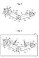
FIG. 6 is a schematic diagram illustrating pulleys and the timing belts according to an illustrative embodiment of the present invention; -
FIG. 7 is a schematic diagram illustrating tension springs that press tensioners against the timing belts according to an illustrative embodiment of the present invention; -
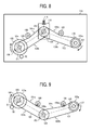
FIG. 8 is a schematic diagram illustrating the drive unit including the relay pulley rotatably supported by a pulley support member; and -
FIG. 9 is a schematic diagram illustrating the drive unit when assembled based on the maximum displacement position in one rotation of the tensioners. - A description is now given of illustrative embodiments of the present invention. It should be noted that although such terms as first, second, etc. may be used herein to describe various elements, components, regions, layers and/or sections, it should be understood that such elements, components, regions, layers and/or sections are not limited thereby because such terms are relative, that is, used only to distinguish one element, component, region, layer or section from another region, layer or section. Thus, for example, a first element, component, region, layer or section discussed below could be termed a second element, component, region, layer or section without departing from the teachings of this disclosure.
- In addition, it should be noted that the terminology used herein is for the purpose of describing particular embodiments only and is not intended to be limiting of this disclosure. Thus, for example, as used herein, the singular forms "a", "an" and "the" are intended to include the plural forms as well, unless the context clearly indicates otherwise. Moreover, the terms "includes" and/or "including", when used in this specification, specify the presence of stated features, integers, steps, operations, elements, and/or components, but do not preclude the presence or addition of one or more other features, integers, steps, operations, elements, components, and/or groups thereof.
- In describing illustrative embodiments illustrated in the drawings, specific terminology is employed for the sake of clarity. However, the disclosure of this patent specification is not intended to be limited to the specific terminology so selected, and it is to be understood that each specific element includes all technical equivalents that operate in a similar manner and achieve a similar result.
- In a later-described comparative example, illustrative embodiment, and alternative example, for the sake of simplicity, the same reference numerals will be given to constituent elements such as parts and materials having the same functions, and redundant descriptions thereof omitted.
- Typically, but not necessarily, paper is the medium from which is made a sheet on which an image is to be formed. It should be noted, however, that other printable media are available in sheet form, and accordingly their use here is included. Thus, solely for simplicity, although this Detailed Description section refers to paper, sheets thereof, paper feeder, etc., it should be understood that the sheets, etc., are not limited only to paper, but include other printable media as well.
- Referring now to the drawings, wherein like reference numerals designate identical or corresponding parts throughout the several views, and initially with reference to
FIG. 2 , a description is provided of an image forming apparatus according to an aspect of this disclosure. -
FIG. 2 is a schematic diagram illustrating an image forming apparatus employing a drive unit according to an illustrative embodiment of the present invention. The image forming apparatus illustrated inFIG. 2 is a tandem-type image forming apparatus in which a plurality of image forming units, one for each of the colors black (B), yellow (Y), magenta (M), and cyan (C), are arranged tandem in ahousing 200 serving as a main body of the image forming apparatus. The image forming units form a respective color image. It is to be noted that suffixes B, Y, M, and C denote colors black, yellow, magenta, and cyan, respectively. These suffixes indicating the colors are omitted, unless otherwise specified. The plurality of image forming units includes tonerimage forming devices optical writing units photosensitive drums transfer rollers - The
photosensitive drums intermediate transfer belt 21 formed into an endless loop. Thephotosensitive drums intermediate transfer belt 21. Each of theoptical writing units photosensitive drums - After the
photosensitive drums image forming devices photosensitive drums optical writing units photosensitive drums - The electrostatic latent images formed on the
photosensitive drums image forming devices intermediate transfer belt 21 is formed into a loop and entrained around adrive roller 5 and a tension roller 6. Thedrive roller 5 is driven to rotate by a drive unit which will be described later. Theintermediate transfer belt 21 rotates at the same peripheral speed as that of thephotosensitive drums intermediate transfer belt 21 such that they are superimposed one atop the other, thereby forming a composite toner image. This process is known as a primary transfer process. - In the meantime, a recording medium P serving as a transfer medium stored in a sheet tray is fed to a sheet transport path by
sheet feed rollers sheet transport rollers registration rollers 10. The pair ofregistration rollers 10 stops temporarily the recording medium P and sends it again to a secondary transfer nip between theintermediate transfer belt 21 and a secondary roller 7 in appropriate timing such that the recording medium P is aligned with the composite toner image formed on theintermediate transfer belt 21. - At the secondary transfer nip, the toner image formed on the
intermediate transfer belt 21 is transferred onto the recording medium P in a process known as a secondary transfer process, thereby forming a full-color image on the recording medium P. The recording medium P bearing the unfixed composite color toner image is sent to afixing device 8 disposed downstream from the secondary transfer nip. In thefixing device 8, heat and pressure are applied to the unfixed composite color toner image on the recording medium P, thereby fixing the unfixed toner image thereon. After the fixing process, the recording medium P is output onto a sheet output tray by a pair of sheet output rollers 9. - In such an image forming apparatus, rotation accuracy of the
intermediate transfer belt 21 and thephotosensitive drums photosensitive drums intermediate transfer belt 21 serving as the image bearing members are rotated by a drive unit 100 (shown inFIG. 1 ) described below. In the present illustrative embodiment, the drive unit described below can rotatephotosensitive drums intermediate transfer belt 21 with precision, thereby obtaining a high-quality image. - With reference to
FIG. 1 , a description is provided of thedrive unit 100 using arelay pulley 104 according to an illustrative embodiment of the present invention.FIG. 1 is a schematic diagram illustrating thedrive unit 100 with therelay pulley 104. Thedrive unit 100 includes an intermediate-transfer driveroller shaft gear 5a, a drive-motor shaft gear 50 for the drive motor serving as a drive source, adrive timing belt 101 including teeth formed on an inner circumference thereof at a predetermined pitch, and a driventiming belt 102 including teeth formed on an inner circumference thereof at a predetermined pitch. - Furthermore, the drive unit includes a
drive pulley 103 including teeth formed at the same pitch as the teeth of thedrive timing belt 101, and adrive pulley gear 103a coaxially provided to the same shaft as thedrive pulley 103, thereby constituting a single integrated unit with thedrive pulley 103. The teeth of thedrive pulley 103 mesh with the teeth of thedrive timing belt 101. The teeth of thedrive pulley gear 103a mesh with the drive-motor shaft gear 50. - Furthermore, the drive unit includes a
relay pulley 104, a drivenpulley 105, and a drivenpulley gear 105a. Therelay pulley 104 includes teeth on an outer circumference thereof at the same pitch as the teeth of thedrive timing belt 101 and the driventiming belt 102. The teeth of therelay pulley 104 mesh with the teeth of thedrive timing belt 101 and the driventiming belt 102. The drivenpulley 105 includes teeth formed at the same pitch as the teeth of the driventiming belt 102, and meshes with the teeth of the driventiming belt 102. The drivenpulley gear 105a is coaxially provided to the same shaft as the drivenpulley 105 and constituted as a single integrated unit with the drivenpulley 105. The drivenpulley gear 105a meshes with the intermediate-transfer driveroller shaft gear 5a. - In
FIG. 1 , amark 106 represents a direction and a position of thedrive timing belt 101. Amark 107 represents a direction and a position of the driventiming belt 102. Atensioner 108 provides tension on thedrive timing belt 101. Atensioner 109 provides tension on the driventiming belt 102. - The
drive pulley 103 is driven by driving thedrive pulley gear 103a meshing with the drive-motor shaft gear 50. As thedrive pulley 103 is rotated, power is transmitted to therelay pulley 104 via thedrive timing belt 101, thereby rotating therelay pulley 104. As thedrive pulley 104 is rotated, power is transmitted to the drivenpulley 105 via the driventiming belt 102, moving the drivenpulley gear 105a coaxially provided on the same shaft as the drivenpulley 105. The drivenpulley gear 105a meshes with the intermediate-transfer driveroller shaft gear 5a, thereby rotating thedrive roller 5. - With reference to
FIG. 3 , a description is provided of positional relations of marks of the timing belts.FIG. 3 is a schematic diagram illustrating the positional relations of marks on the timing belts according to an illustrative embodiment of the present invention. Abelt member 120 shown inFIG. 3 is an endless belt having a width wider than thedrive timing belt 101 and the driventiming belt 102. Amark 122 is provided at one place on the circumference of thebelt member 120. Thebelt member 120 is divided into a plurality ofbelts 120a having the same width (in this example, the belt member is divided into five belts). - The obtained
belt strips 120a each having the same and relatively narrow width are hereinafter referred to astiming belts 120a. Thetiming belts 120a are used as thedrive timing belt 101 and the driventiming belt 102. Each of thetiming belts 120a includes themark 122 which indicates a direction and a position, and corresponds to themark 106 on thedrive timing belt 101 and themark 107 on the driventiming belt 102 illustrated inFIG. 1 . Before being divided, themarks 122 are formed on the same straight line on thebelt member 120 and face in the same direction. - Upon assembly of elements of the drive unit, the
marks drive timing belt 101 and the driventiming belt 102 are distributed. With this configuration, thedrive timing belt 101 and the driventiming belt 102 are positioned such that the eccentric components of thedrive timing belt 101 and the driventiming belt 102 cancel one another on the drivenpulley 105. - With reference to
FIG. 4 , a description is provided of a cyclic speed variation of a single timing belt in one rotation.FIG. 4 illustrates a cyclic speed variation of a single timing belt in one rotation period. As illustrated inFIG. 4 , as aspeed variation 131, a single timing belt always has a cyclic speed variation in one rotation period due to irregularity of the thickness of the timing belt itself. -
FIG. 5 illustrates a speed variation of two timing belts when two timing belts are assembled in phase. InFIG. 5 ,reference numeral 132 represents a speed variation of thedrive timing belt 101, andreference numeral 133 represents a speed variation of the driventiming belt 102.Reference numeral 134 represents a speed variation occurring on the drivenpulley 105 when thedrive timing belt 101 and the driventiming belt 102 are assembled in phase. - As described above, the timing belt has a cyclic speed variation in one rotation. The
drive timing belt 101 and the driventiming belt 102 have the same length, and the speed variation of thedrive timing belt 101 and the speed variation of the driventiming belt 102 have the same amplitude. Thus, upon assembly, thedrive timing belt 101 and the driventiming belt 102 are shifted by 180 degrees. With this configuration, as illustrated inFIG. 5 , the cyclic speed variation of the timing belts in one rotation period is cancelled on the drivenpulley 105 as indicated byreference numeral 134. - As for the
drive timing belt 101, the rotational force of thedrive pulley 103 causes thedrive timing belt 101 to rotate. Thus, asurface 101b of thedrive timing belt 101, being pulled by thedrive pulley 103 and moving from therelay pulley 104 to the drivepulley 103, is relatively stretched. By contrast, asurface 101a of thedrive timing belt 101, sent from thedrive pulley 103 to therelay pulley 104, retains slack. - As for the driven
timing belt 102, the rotational force of therelay pulley 104 causes the driven timing belt to rotate. Thus, asurface 102b of the driventiming belt 102, being pulled by therelay pulley 104 and moving from the drivenpulley 105 to therelay pulley 104, is relatively stretched. By contrast, asurface 102a of the driventiming belt 102, sent from therelay pulley 104 to the drivenpulley 105, retains slack. - If there is a sudden change in the load, unless the tension of the
drive timing belt 101 and the driventiming belt 102 is optimized, thedrive timing belt 101 and the driventiming belt 102 cannot rotate in accordance with the force transmitted from the drive motor, causing speed fluctuations. - A sudden change in the speed occurs when a recording medium P passes through the secondary transfer nip between the secondary transfer roller 7 and the
drive roller 5 via theintermediate transfer belt 21, for example. More specifically, as the leading edge of the recording medium P enters the secondary transfer nip between the secondary transfer roller 7 and thedrive roller 5 via theintermediate transfer belt 21, the recording medium P pushes the secondary transfer roller 7 and thedrive roller 5 via theintermediate transfer belt 21, widening the secondary transfer nip by an amount of the thickness of the recording medium P. As a result, a load is suddenly applied to thedrive roller 5 and the drivenpulley 105, causing rotation of the drivenpulley 105 to slow down temporarily. - Such a sudden speed fluctuation changes the tension of the
drive timing belt 101 and the driventiming belt 102. The tension of thedrive timing belt 101 and the driventiming belt 102 may no longer be optimized. More specifically, the sudden load on the drivenpulley 105 slows down the rotation of the drivenpulley 105 temporarily. Consequently, an amount of the belt sent from therelay pulley 104 to the drivenpulley 105 becomes more than an amount of the belt moving from the drivenpulley 105 to therelay pulley 104, and the portion of the driventiming belt 102 between therelay pulley 104 and the drivenpulley 105 retains slack, reducing the tension of the belt. - Furthermore, as the rotation speed of the
relay pulley 104 is reduced temporarily, the amount of the belt sent from the drivenpulley 105 to therelay pulley 104 is reduced so that the driventiming belt 102 decelerates therelay pulley 104. That is, rotation of therelay pulley 104 slows down temporarily. As a result, the amount of the belt sent from thedrive pulley 103 to therelay pulley 104 becomes greater than the amount of the belt sent from therelay pulley 104 to the drivepulley 103, thereby reducing the tension of the portion of thedrive timing belt 101 between thedrive pulley 103 and therelay pulley 104. Thedrive timing belt 101 between thedrive pulley 103 and therelay pulley 104 retains slack. - As described above, such a sudden load on the driven
pulley 105 changes the belt tension between thedrive timing belt 101 and the driventiming belt 102. The change in the tension causes fluctuation of the speed of thedrive timing belt 101 and the driventiming belt 102. Consequently, the fluctuation of the speed of thedrive timing belt 101 and the driventiming belt 102 is transmitted to the drivenpulley 105, causing the speed of the drivenpulley 105 to fluctuate. The change in the speed of the drivenpulley 105 results in fluctuation of the speed of theintermediate transfer belt 21 via thedrive roller 5. As a result, toner images transferred from thephotosensitive drums intermediate transfer belt 21 are misformed, i.e., shrunk or stretched, causing irregular image density in the resulting output image. Because the toner images in different colors are transferred from thephotosensitive drums intermediate transfer belt 21 such that they are superimposed one atop the other, the change in the speed of theintermediate transfer belt 21 causes color drift in the composite toner image. - In view of the above, according to the present illustrative embodiment, the
tensioner 108 is provided at thedrive timing belt 101 side sent from thedrive pulley 103 and therelay pulley 104. More specifically, thetensioner 108 contacts thesurface 101a of thedrive timing belt 101 which retains slack. Thetensioner 109 is provided at the driventiming belt 102 side sent from therelay pulley 104 and the drivenpulley 105. More specifically, thetensioner 109 contacts thesurface 102a of the driventiming belt 102 which retains slack. Thetensioner 108 provides tension to thedrive timing belt 101. Thetensioner 109 provides tension to the driventiming belt 102. With this configuration, thedrive timing belt 101 and the driventiming belt 102 are prevented from slackening, thereby optimizing the tension of thedrive timing belt 101 and the driventiming belt 102 to prevent fluctuation of the speed due to sudden changes in the load. - The
tensioner 108 contacts thesurface 101a of thedrive timing belt 101 at the slackening side, and thetensioner 109 contacts thesurface 102a of the driventiming belt 102 at the slackening side. With this configuration, the influence of irregularity of the thickness of the timing belts in the circumferential direction is suppressed, thereby preventing fluctuation of the speed. - With reference to
FIG. 6 , a description is provided of a winding angle of the timing belts around the pulleys. InFIG. 6 , an angle θ1 is a winding angle of thedrive timing belt 101 around thedrive pulley 103 and is determined based on the position of thetensioner 108 relative to thedrive timing belt 101. An angle θ2 is a winding angle of the driventiming belt 102 around therelay pulley 104 and is determined based on the position of thetensioner 109 relative to the driventiming belt 102. - According to the present illustrative embodiment, the
tensioners drive timing belt 101 and the driventiming belt 102 are the same, thereby preventing the cyclic speed variation of the timing belts in one rotation period caused by different rotation paths. - With reference to
FIG. 7 , a description is provided of installation of thetensioners FIG. 7 , thetensioner 108 is movably supported by asupport member 113a to which aspring 112a is attached. Thetensioner 109 is movably supported by asupport member 113b to which aspring 112b is attached. Thesupport members main body 110 of thedrive unit 100. Thesprings tensioners drive timing belt 101 and the driventiming belt 102, respectively, via thesupport members drive timing belt 101 and the driventiming belt 102. With this configuration, the cyclic speed variation of the timing belts in one rotation caused by the relative difference in tension is prevented. - With reference to
FIG. 8 , a description is provided of a support mechanism for therelay pulley 104. In the present illustrative embodiment, therelay pulley 104 is rotatably supported by apulley support member 114 which is movably disposed relative to amain body 110 of thedrive unit 100. As the tensile force of aspring 115 pulls up thepulley support member 114, moving therelay pulley 104 up, thedrive timing belt 101 is pressed against thetensioner 108 and the driventiming belt 102 is pressed against thetensioner 109, thereby providing the same tension to thedrive timing belt 101 and the driventiming belt 102. With this configuration, the cyclic speed variation of the timing belts in one rotation caused by the relative difference in tension is prevented. - With reference to
FIG. 9 , a description is provided of assembly of thedrive unit 100 using a mark provided at a maximum displacement position of the eccentric component of each of thetensioners - In
FIG. 9 , amark 108a is provided at a maximum displacement position of the eccentric component of thetensioner 108 in one rotation period, and amark 109a is provided at a maximum displacement position of the eccentric component of thetensioner 109 in one rotation period. As illustrated inFIG. 9 , upon assembly of thetensioners mark 108a of thetensioner 108 and themark 109a of thetensioner 109 are aligned. More specifically, themark 108a is brought to a position at which thedrive timing belt 101 and thetensioner 108 contact. Themark 109a is brought to a position at which the driventiming belt 102 and thetensioner 109 contact. With this configuration, the eccentric components in one rotation period of thetensioner 108 and thetensioner 109 are canceled one another. - Furthermore, in the image forming apparatus for producing a color image as illustrated in
FIG. 2 , the image forming units are arranged in tandem at predetermined intervals (also referred to as station pitch) between each other. In other words, the station pitch is a distance between adjacent image forming units, and the image forming units are disposed equally spaced. The reference position for the station pitch of each image forming unit is provided substantially at the center of the primary transfer nip in the direction of rotation of the intermediate transfer belt, at which the photosensitive drum 3 and the transfer roller 4 meet via theintermediate transfer belt 21. One rotation period of thetensioners tensioners - Preferably, one rotation period of the
tensioners tensioners - In the present illustrative embodiment, the photosensitive drums and the intermediate transfer belt are rotated by the
drive unit 100 in the image forming apparatus. Thedrive unit 100 of the illustrative embodiment of the present invention can be applied to an image forming apparatus using a transfer drum serving as an image bearing member to rotate the transfer drum. For example, thedrive unit 100 may be employed in a color copier in which latent images formed on a closed-loop photosensitive belt are developed with toner and transferred onto the transfer drum which is rotated by thedrive unit 100. Then, the composite toner image on the transfer drum is transferred onto a recording medium. - Furthermore, the drive unit of the illustrative embodiment of the present invention may be employed in the image forming apparatus using the direct-transfer method. In this configuration, the toner images formed on the photosensitive drums serving as image bearing members facing a transfer belt are transferred directly onto a recording medium carried on the transfer belt. The transfer belt and the photosensitive drums are driven by the
drive unit 100 of the present invention. - In the present illustrative embodiment, the
drive timing belt 101 and the driventiming belt 102 are arranged relative to therelay pulley 104 in the rotation shaft direction of therelay pulley 104. However, the number of relay pulleys is not limited to one. More than one relay pulley may be provided. For example, when using two relay pulleys, thedrive timing belt 101 is entrained around thedrive pulley 103 and a first relay pulley. The driventiming belt 102 is entrained around a second relay pulley and the drivenpulley 105. Similar to thetiming belt 120a illustrated inFIG. 3 , thetiming belts 120a serving as thedrive timing belt 101 and thesecond timing belt 102 are entrained around the first relay pulley and the second relay pulley. Each timing belt entrained around the pulleys may be disposed such that the cyclic speed variation of each timing belt in one rotation period are canceled one another on the drivenpulley 105. - A tensioner may contact the slackening surface of the timing belt entrained around and stretched taut between the first relay pulley and the second relay pulley so as to provide tension thereto. With this configuration, even when there is a sudden change in the load, the speed fluctuation can be prevented. In this case, the tensioner may be provided in a similar manner as the
tensioner 108 and thetensioner 109 described above. - Although the embodiment of the present invention has been described above, the present invention is not limited to the foregoing embodiments, but a variety of modifications can naturally be made within the scope of the present invention.
- A drive unit includes a drive pulley (i.e., the drive pulley 103) connected to a drive source such as a drive motor; a driven pulley (i.e., the driven pulley 105) connected to a target to be moved (i.e., the intermediate-transfer drive
roller shaft gear 5a); at least one relay pulley (i.e., the relay pulley 104) to transmit power from the drive pulley to the driven pulley; a plurality of belts entrained around and stretched taut between the drive pulley, the driven pulley, and the relay pulley, the plurality of belts including a first belt (i.e., the drive timing belt 101) entrained around the drive pulley and the relay pulley, and a second belt entrained around the relay pulley and the driven pulley; a first tension application device (i.e., the tensioner 108) to contact the first belt to provide tension thereto; and a second tension application device (i.e., the tensioner 109) to contact the second belt to provide tension thereto. The first belt and the second belt have a positional relation in a direction of rotation thereof in that a speed variation component in one rotation period of the first belt transmitted to the driven pulley via the relay pulley and a speed variation component in one rotation period of the second belt transmitted to the driven pulley counteract each other. - With this configuration, even when there is a sudden change in the load, a cyclic speed variation of the timing belts in one rotation period thereof is reduced, if not prevented entirely.
- According to an aspect of the disclosure, the first tension application device contacts a surface (i.e., the
surface 101a) of the first belt which slackens, and the second tension application device contacts a surface of the second belt (i.e., thesurface 102a) which slackens. With this configuration, the influence of irregularity of the thickness of the timing belts in the circumferential direction is suppressed, thereby preventing fluctuation of the speed. - According to an aspect of the disclosure, the first tension application device and the second tension application device are disposed such that a winding angle of the first belt wound around the drive pulley coincides with a winding angle of the second belt wound around the relay pulley. Accordingly, the cyclic speed variation of the timing belts in one rotation period thereof caused by different rotation paths of the first belt and the second belt is canceled.
- According to an aspect of the disclosure, the first tension application device provides tension to the first belt, and the second tension application device provided tension to the second belt such that the tension of the first belt and that of the second belt are the same. Accordingly, the cyclic speed variation of the timing belts in one rotation period thereof caused by different tension of the first belt and the second belt is reduced, if not prevented entirely.
- According to an aspect of the disclosure, the relay pulley is movable relative to a housing (i.e., the housing 110) of the drive unit. By moving the relay pulley, the first roller (i.e., the tensioner 108) contacts the first belt and the second roller (i.e., the tensioner 109) contacts the second belt. Accordingly, the cyclic speed variation of the timing belts in one rotation period thereof caused by different tension of the first belt and the second belt is reduced, if not prevented entirely.
- According to an aspect of the disclosure, each of the first roller of the first tension application device and the second roller of the second tension application device includes a mark (i.e., the
marks - According to an aspect of the disclosure, an image forming apparatus is equipped with an image forming mechanism to form an image, a housing to house the image forming unit, and the above-described drive unit to drive a target provided to the housing. With this configuration, even when there is a sudden change in the load, a cyclic speed variation in one rotation period of the timing belts and the tensioners is reduced, if not prevented entirely, and hence preventing image defects such as color drift.
- According to an aspect of the disclosure, the image forming mechanism include a plurality of image forming units (i.e., 1K, 1Y, 1M, and 1C) arranged in a certain direction Each of the plurality of image forming units includes an image bearing member (i.e., the
photosensitive drums tensioners 108 and 109) is 1/n times a station pitch, where n is an integer and the pitch station is a distance between adjacent image forming units. With this configuration, image defects such as color drift are prevented. - According to an aspect of the disclosure, the image forming apparatus further includes a latent image forming device (i.e., the
optical writing units transfer rollers - According to an aspect of the disclosure, the target to be driven by the drive unit includes at least one of an intermediate transfer belt, a transfer drum, a photosensitive drum, and a direct transfer belt. With this configuration, image defects such as color drift are prevented.
- According to an aspect of this disclosure, the present invention is employed in the image forming apparatus. The image forming apparatus includes, but is not limited to, an electrophotographic image forming apparatus, a copier, a printer, a facsimile machine, and a multi-functional system.
- Furthermore, it is to be understood that elements and/or features of different illustrative embodiments may be combined with each other and/or substituted for each other within the scope of this disclosure and appended claims. In addition, the number of constituent elements, locations, shapes and so forth of the constituent elements are not limited to any of the structure for performing the methodology illustrated in the drawings.
- Example embodiments being thus described, it will be obvious that the same may be varied in many ways. Such exemplary variations are not to be regarded as a departure from the scope of the present invention, and all such modifications as would be obvious to one skilled in the art are intended to be included within the scope of the following claims.
Claims (10)
- A drive unit (100), comprising:a drive pulley (103) connected to a drive source;a driven pulley (105) connected to a target to be moved;at least one relay pulley (104) to transmit power from the drive pulley to the driven pulley;a plurality of belts (101, 102) entrained around and stretched taut between the drive pulley, the driven pulley, and the relay pulley, the plurality of belts including a first belt (101) entrained around the drive pulley (103) and the relay pulley (104), and a second belt (102) entrained around the relay pulley (104) and the driven pulley (105);a first tension application device (108) to contact the first belt to provide tension thereto; anda second tension application device (109) to contact the second belt to provide tension thereto,wherein the first belt and the second belt have a positional relation in a direction of rotation thereof in that a cyclic speed variation component in one rotation period of the first belt transmitted to the driven pulley via the relay pulley and a speed variation component in one rotation period of the second belt transmitted to the driven pulley counteract each other.
- The drive unit according to claim 1, wherein the first tension application device (108) contacts a surface (101a) of the first belt (101) which slackens, and the second tension application device (109) contacts a surface (102a) of the second belt (102) which slackens.
- The drive unit according to claim 1 or claim 2, wherein the first tension application device and the second tension application device are disposed such that a winding angle of the first belt wound around the drive pulley coincides with a winding angle of the second belt wound around the relay pulley.
- The drive unit according to any one of claims 1 through 3, wherein the first tension application device and the second tension application device provide tension to the first belt and the second tension such that the tension of the first belt coincides with the tension of the second belt.
- The drive unit according to any one of claims 1 through 4, further comprising a housing (110),
wherein the first tension application device includes a first roller (108) and the second tension application device includes a second roller (109), and the relay pulley is movably disposed relative to the housing;
wherein as the relay pulley is moved, the first belt is pressed against the first roller and the second belt is pressed against the second roller. - The drive unit according to any one of claims 1 through 5, wherein each of the first roller of the first tension application device and the second roller of the second tension application device includes a mark (108a, 109a) by which a phase of one rotation period of the first roller and a phase of one period of rotation of the second roller are aligned.
- An image forming apparatus, comprising:a housing (200);an image forming unit to form an image; andthe drive unit of any one of claims 1 to 6 to drive a target disposed in the housing,wherein the image forming unit and the drive unit are disposed in the housing.
- The image forming apparatus according to claim 7, further comprising a plurality of the image forming units arranged in a certain direction, each of the plurality of image forming units including an image bearing member (3K, 3Y, 3M, 3C),
wherein one rotation period of each of the first and the second rollers is 1/n times a station pitch, where n is a positive integer and the station pitch is a distance between adjacent image forming units. - The image forming apparatus according to claim 7 or 8, further comprising:a latent image forming device (2K, 2Y, 2M, 2C) disposed near the image bearing member, to expose the surface of the image bearing member at an exposure position to form a latent image thereon;a developing device (1K, 1Y, 1M, 1C) to develop the latent image with a developing agent to form a toner image; anda transfer device (4K, 4Y, 4M, 4C) to transfer the toner image from a transfer position of the image bearing member onto a transfer medium,wherein one rotation period of each of the first and the second rollers is 1/n times a distance between the exposure position and the transfer position in the direction of rotation of the image bearing member, where n is a positive integer.
- The image forming apparatus according to any one of claims 7 through 9, wherein the target to be driven by the drive unit includes at least one of an intermediate transfer belt, a transfer drum, a photosensitive drum, and a direct transfer belt.
Applications Claiming Priority (1)
| Application Number | Priority Date | Filing Date | Title |
|---|---|---|---|
| JP2012063565A JP5900796B2 (en) | 2012-03-21 | 2012-03-21 | Driving device and image forming apparatus |
Publications (3)
| Publication Number | Publication Date |
|---|---|
| EP2642160A2 true EP2642160A2 (en) | 2013-09-25 |
| EP2642160A3 EP2642160A3 (en) | 2015-10-21 |
| EP2642160B1 EP2642160B1 (en) | 2021-01-13 |
Family
ID=47750455
Family Applications (1)
| Application Number | Title | Priority Date | Filing Date |
|---|---|---|---|
| EP13155486.7A Active EP2642160B1 (en) | 2012-03-21 | 2013-02-15 | Drive unit and image forming apparatus including same |
Country Status (4)
| Country | Link |
|---|---|
| US (2) | US8903279B2 (en) |
| EP (1) | EP2642160B1 (en) |
| JP (1) | JP5900796B2 (en) |
| CN (1) | CN103324055B (en) |
Families Citing this family (3)
| Publication number | Priority date | Publication date | Assignee | Title |
|---|---|---|---|---|
| TW201350352A (en) * | 2012-06-04 | 2013-12-16 | Hon Hai Prec Ind Co Ltd | Belt adjusting device for printer |
| JP6723859B2 (en) * | 2016-07-29 | 2020-07-15 | キヤノン株式会社 | Image reader |
| IT202200025833A1 (en) * | 2022-12-16 | 2024-06-16 | Ital Res & Innovation Srl | SELECTIVE DRIVE COMBINED MACHINE |
Family Cites Families (18)
| Publication number | Priority date | Publication date | Assignee | Title |
|---|---|---|---|---|
| US4146105A (en) * | 1977-05-13 | 1979-03-27 | Wisconsin Marine, Inc. | Lawn mower |
| US4870516A (en) * | 1983-05-20 | 1989-09-26 | Dictaphone Corporation | Portable dictating machine |
| JP2938776B2 (en) * | 1995-01-09 | 1999-08-25 | 株式会社クボタ | Reverse drive mechanism for cooling air supply fan of work equipment |
| JPH10186759A (en) * | 1996-12-20 | 1998-07-14 | Canon Inc | Drive transmission device for image forming apparatus |
| JP2000010373A (en) * | 1998-06-26 | 2000-01-14 | Matsushita Electric Ind Co Ltd | Image forming device |
| JP2000267379A (en) | 1999-03-16 | 2000-09-29 | Fuji Xerox Co Ltd | Image forming device |
| JP3589112B2 (en) * | 1999-09-16 | 2004-11-17 | 松下電器産業株式会社 | Image forming device |
| JP2001227608A (en) * | 2000-02-16 | 2001-08-24 | Canon Inc | Reduction gear |
| JP2001315294A (en) * | 2000-02-29 | 2001-11-13 | Tohoku Ricoh Co Ltd | Printing apparatus |
| JP4634565B2 (en) | 2000-03-09 | 2011-02-16 | 東北リコー株式会社 | Printing device |
| JP4107542B2 (en) * | 2000-07-28 | 2008-06-25 | 株式会社リコー | Rotor driving device for image forming apparatus |
| EP1345088B1 (en) * | 2002-03-14 | 2008-06-11 | Ricoh Company, Ltd. | Colour image forming apparatus avoiding speed related pixel size variation |
| JP4252273B2 (en) * | 2002-09-11 | 2009-04-08 | 株式会社リコー | Rotation drive transmission device, image forming apparatus, image reading apparatus, and timing belt |
| JP2007002963A (en) * | 2005-06-27 | 2007-01-11 | Murata Mach Ltd | Power transmission mechanism, and image formation device having the same |
| JP4871716B2 (en) * | 2006-12-14 | 2012-02-08 | キヤノン株式会社 | Drive transmission device |
| US20090239713A1 (en) * | 2008-03-20 | 2009-09-24 | Chu Yong S | Cyclic skating motion exercise machines |
| JP2011043697A (en) * | 2009-08-21 | 2011-03-03 | Seiko Epson Corp | Image forming apparatus and transfer device |
| JP5870648B2 (en) | 2011-02-08 | 2016-03-01 | 株式会社リコー | Synchronous drive device and image forming apparatus having the same |
-
2012
- 2012-03-21 JP JP2012063565A patent/JP5900796B2/en active Active
-
2013
- 2013-02-13 US US13/766,140 patent/US8903279B2/en active Active
- 2013-02-15 EP EP13155486.7A patent/EP2642160B1/en active Active
- 2013-03-14 CN CN201310081866.5A patent/CN103324055B/en active Active
-
2014
- 2014-10-31 US US14/529,829 patent/US9188930B2/en active Active
Non-Patent Citations (1)
| Title |
|---|
| None |
Also Published As
| Publication number | Publication date |
|---|---|
| US20150050051A1 (en) | 2015-02-19 |
| US9188930B2 (en) | 2015-11-17 |
| CN103324055A (en) | 2013-09-25 |
| EP2642160B1 (en) | 2021-01-13 |
| EP2642160A3 (en) | 2015-10-21 |
| JP5900796B2 (en) | 2016-04-06 |
| US8903279B2 (en) | 2014-12-02 |
| CN103324055B (en) | 2016-03-02 |
| JP2013194845A (en) | 2013-09-30 |
| US20130251404A1 (en) | 2013-09-26 |
Similar Documents
| Publication | Publication Date | Title |
|---|---|---|
| US8600266B2 (en) | Drive transmission device and image forming apparatus including same | |
| US10656565B2 (en) | Drive transmission device and image forming apparatus incorporating the drive transmission device | |
| JP2010281943A (en) | Image forming apparatus | |
| US10322893B2 (en) | Image forming apparatus | |
| US20130216260A1 (en) | Image forming apparatus | |
| US8824930B2 (en) | Synchronized drive unit and image forming apparatus having the synchronized drive unit | |
| US8335458B2 (en) | Image forming apparatus | |
| US9188930B2 (en) | Drive unit and image forming apparatus including same | |
| JP6128757B2 (en) | Belt conveying apparatus and image forming apparatus | |
| JP5610837B2 (en) | Image forming apparatus | |
| JP2002182450A (en) | Image forming device | |
| JP2010102247A (en) | Drive force transmission mechanism for image carrier, image forming apparatus having the same, and drive force transmission method for image carrier | |
| JP7229695B2 (en) | image forming device | |
| CN114460825A (en) | Image forming apparatus with a plurality of image forming units | |
| JP4857022B2 (en) | Image forming apparatus | |
| JP5483185B2 (en) | Image forming apparatus | |
| JP5162815B2 (en) | Image forming apparatus | |
| JP2012220745A (en) | Displacement mechanism of secondary transfer unit, and image-forming device | |
| US8532513B2 (en) | Image forming apparatus | |
| JP5397757B2 (en) | Driving device and image forming apparatus | |
| CN100414455C (en) | image forming device | |
| JP2007052246A (en) | Image forming apparatus | |
| JP2004197909A (en) | Apparatus for transmitting driving force, and apparatus for forming image using the same | |
| JP2008145637A (en) | Image forming apparatus | |
| JP2002123129A (en) | Image forming device |
Legal Events
| Date | Code | Title | Description |
|---|---|---|---|
| PUAI | Public reference made under article 153(3) epc to a published international application that has entered the european phase |
Free format text: ORIGINAL CODE: 0009012 |
|
| 17P | Request for examination filed |
Effective date: 20130215 |
|
| AK | Designated contracting states |
Kind code of ref document: A2 Designated state(s): AL AT BE BG CH CY CZ DE DK EE ES FI FR GB GR HR HU IE IS IT LI LT LU LV MC MK MT NL NO PL PT RO RS SE SI SK SM TR |
|
| AX | Request for extension of the european patent |
Extension state: BA ME |
|
| PUAL | Search report despatched |
Free format text: ORIGINAL CODE: 0009013 |
|
| AK | Designated contracting states |
Kind code of ref document: A3 Designated state(s): AL AT BE BG CH CY CZ DE DK EE ES FI FR GB GR HR HU IE IS IT LI LT LU LV MC MK MT NL NO PL PT RO RS SE SI SK SM TR |
|
| AX | Request for extension of the european patent |
Extension state: BA ME |
|
| RIC1 | Information provided on ipc code assigned before grant |
Ipc: G03G 15/16 20060101ALI20150917BHEP Ipc: F16H 7/12 20060101AFI20150917BHEP |
|
| STAA | Information on the status of an ep patent application or granted ep patent |
Free format text: STATUS: EXAMINATION IS IN PROGRESS |
|
| 17Q | First examination report despatched |
Effective date: 20190221 |
|
| GRAP | Despatch of communication of intention to grant a patent |
Free format text: ORIGINAL CODE: EPIDOSNIGR1 |
|
| STAA | Information on the status of an ep patent application or granted ep patent |
Free format text: STATUS: GRANT OF PATENT IS INTENDED |
|
| INTG | Intention to grant announced |
Effective date: 20200825 |
|
| GRAS | Grant fee paid |
Free format text: ORIGINAL CODE: EPIDOSNIGR3 |
|
| GRAA | (expected) grant |
Free format text: ORIGINAL CODE: 0009210 |
|
| STAA | Information on the status of an ep patent application or granted ep patent |
Free format text: STATUS: THE PATENT HAS BEEN GRANTED |
|
| AK | Designated contracting states |
Kind code of ref document: B1 Designated state(s): AL AT BE BG CH CY CZ DE DK EE ES FI FR GB GR HR HU IE IS IT LI LT LU LV MC MK MT NL NO PL PT RO RS SE SI SK SM TR |
|
| REG | Reference to a national code |
Ref country code: GB Ref legal event code: FG4D |
|
| REG | Reference to a national code |
Ref country code: CH Ref legal event code: EP |
|
| REG | Reference to a national code |
Ref country code: IE Ref legal event code: FG4D |
|
| REG | Reference to a national code |
Ref country code: DE Ref legal event code: R096 Ref document number: 602013075257 Country of ref document: DE |
|
| REG | Reference to a national code |
Ref country code: AT Ref legal event code: REF Ref document number: 1354817 Country of ref document: AT Kind code of ref document: T Effective date: 20210215 |
|
| REG | Reference to a national code |
Ref country code: NL Ref legal event code: FP |
|
| REG | Reference to a national code |
Ref country code: AT Ref legal event code: MK05 Ref document number: 1354817 Country of ref document: AT Kind code of ref document: T Effective date: 20210113 |
|
| REG | Reference to a national code |
Ref country code: LT Ref legal event code: MG9D |
|
| PG25 | Lapsed in a contracting state [announced via postgrant information from national office to epo] |
Ref country code: GR Free format text: LAPSE BECAUSE OF FAILURE TO SUBMIT A TRANSLATION OF THE DESCRIPTION OR TO PAY THE FEE WITHIN THE PRESCRIBED TIME-LIMIT Effective date: 20210414 Ref country code: FI Free format text: LAPSE BECAUSE OF FAILURE TO SUBMIT A TRANSLATION OF THE DESCRIPTION OR TO PAY THE FEE WITHIN THE PRESCRIBED TIME-LIMIT Effective date: 20210113 Ref country code: HR Free format text: LAPSE BECAUSE OF FAILURE TO SUBMIT A TRANSLATION OF THE DESCRIPTION OR TO PAY THE FEE WITHIN THE PRESCRIBED TIME-LIMIT Effective date: 20210113 Ref country code: PT Free format text: LAPSE BECAUSE OF FAILURE TO SUBMIT A TRANSLATION OF THE DESCRIPTION OR TO PAY THE FEE WITHIN THE PRESCRIBED TIME-LIMIT Effective date: 20210513 Ref country code: LT Free format text: LAPSE BECAUSE OF FAILURE TO SUBMIT A TRANSLATION OF THE DESCRIPTION OR TO PAY THE FEE WITHIN THE PRESCRIBED TIME-LIMIT Effective date: 20210113 Ref country code: BG Free format text: LAPSE BECAUSE OF FAILURE TO SUBMIT A TRANSLATION OF THE DESCRIPTION OR TO PAY THE FEE WITHIN THE PRESCRIBED TIME-LIMIT Effective date: 20210413 Ref country code: NO Free format text: LAPSE BECAUSE OF FAILURE TO SUBMIT A TRANSLATION OF THE DESCRIPTION OR TO PAY THE FEE WITHIN THE PRESCRIBED TIME-LIMIT Effective date: 20210413 |
|
| PG25 | Lapsed in a contracting state [announced via postgrant information from national office to epo] |
Ref country code: SE Free format text: LAPSE BECAUSE OF FAILURE TO SUBMIT A TRANSLATION OF THE DESCRIPTION OR TO PAY THE FEE WITHIN THE PRESCRIBED TIME-LIMIT Effective date: 20210113 Ref country code: LV Free format text: LAPSE BECAUSE OF FAILURE TO SUBMIT A TRANSLATION OF THE DESCRIPTION OR TO PAY THE FEE WITHIN THE PRESCRIBED TIME-LIMIT Effective date: 20210113 Ref country code: PL Free format text: LAPSE BECAUSE OF FAILURE TO SUBMIT A TRANSLATION OF THE DESCRIPTION OR TO PAY THE FEE WITHIN THE PRESCRIBED TIME-LIMIT Effective date: 20210113 Ref country code: RS Free format text: LAPSE BECAUSE OF FAILURE TO SUBMIT A TRANSLATION OF THE DESCRIPTION OR TO PAY THE FEE WITHIN THE PRESCRIBED TIME-LIMIT Effective date: 20210113 Ref country code: AT Free format text: LAPSE BECAUSE OF FAILURE TO SUBMIT A TRANSLATION OF THE DESCRIPTION OR TO PAY THE FEE WITHIN THE PRESCRIBED TIME-LIMIT Effective date: 20210113 |
|
| PG25 | Lapsed in a contracting state [announced via postgrant information from national office to epo] |
Ref country code: IS Free format text: LAPSE BECAUSE OF FAILURE TO SUBMIT A TRANSLATION OF THE DESCRIPTION OR TO PAY THE FEE WITHIN THE PRESCRIBED TIME-LIMIT Effective date: 20210513 |
|
| REG | Reference to a national code |
Ref country code: DE Ref legal event code: R097 Ref document number: 602013075257 Country of ref document: DE |
|
| REG | Reference to a national code |
Ref country code: BE Ref legal event code: MM Effective date: 20210228 |
|
| PG25 | Lapsed in a contracting state [announced via postgrant information from national office to epo] |
Ref country code: SM Free format text: LAPSE BECAUSE OF FAILURE TO SUBMIT A TRANSLATION OF THE DESCRIPTION OR TO PAY THE FEE WITHIN THE PRESCRIBED TIME-LIMIT Effective date: 20210113 Ref country code: CH Free format text: LAPSE BECAUSE OF NON-PAYMENT OF DUE FEES Effective date: 20210228 Ref country code: LI Free format text: LAPSE BECAUSE OF NON-PAYMENT OF DUE FEES Effective date: 20210228 Ref country code: MC Free format text: LAPSE BECAUSE OF FAILURE TO SUBMIT A TRANSLATION OF THE DESCRIPTION OR TO PAY THE FEE WITHIN THE PRESCRIBED TIME-LIMIT Effective date: 20210113 Ref country code: LU Free format text: LAPSE BECAUSE OF NON-PAYMENT OF DUE FEES Effective date: 20210215 Ref country code: CZ Free format text: LAPSE BECAUSE OF FAILURE TO SUBMIT A TRANSLATION OF THE DESCRIPTION OR TO PAY THE FEE WITHIN THE PRESCRIBED TIME-LIMIT Effective date: 20210113 Ref country code: EE Free format text: LAPSE BECAUSE OF FAILURE TO SUBMIT A TRANSLATION OF THE DESCRIPTION OR TO PAY THE FEE WITHIN THE PRESCRIBED TIME-LIMIT Effective date: 20210113 |
|
| PLBE | No opposition filed within time limit |
Free format text: ORIGINAL CODE: 0009261 |
|
| STAA | Information on the status of an ep patent application or granted ep patent |
Free format text: STATUS: NO OPPOSITION FILED WITHIN TIME LIMIT |
|
| PG25 | Lapsed in a contracting state [announced via postgrant information from national office to epo] |
Ref country code: RO Free format text: LAPSE BECAUSE OF FAILURE TO SUBMIT A TRANSLATION OF THE DESCRIPTION OR TO PAY THE FEE WITHIN THE PRESCRIBED TIME-LIMIT Effective date: 20210113 Ref country code: SK Free format text: LAPSE BECAUSE OF FAILURE TO SUBMIT A TRANSLATION OF THE DESCRIPTION OR TO PAY THE FEE WITHIN THE PRESCRIBED TIME-LIMIT Effective date: 20210113 Ref country code: DK Free format text: LAPSE BECAUSE OF FAILURE TO SUBMIT A TRANSLATION OF THE DESCRIPTION OR TO PAY THE FEE WITHIN THE PRESCRIBED TIME-LIMIT Effective date: 20210113 Ref country code: ES Free format text: LAPSE BECAUSE OF FAILURE TO SUBMIT A TRANSLATION OF THE DESCRIPTION OR TO PAY THE FEE WITHIN THE PRESCRIBED TIME-LIMIT Effective date: 20210113 |
|
| 26N | No opposition filed |
Effective date: 20211014 |
|
| PG25 | Lapsed in a contracting state [announced via postgrant information from national office to epo] |
Ref country code: AL Free format text: LAPSE BECAUSE OF FAILURE TO SUBMIT A TRANSLATION OF THE DESCRIPTION OR TO PAY THE FEE WITHIN THE PRESCRIBED TIME-LIMIT Effective date: 20210113 Ref country code: IE Free format text: LAPSE BECAUSE OF NON-PAYMENT OF DUE FEES Effective date: 20210215 |
|
| PG25 | Lapsed in a contracting state [announced via postgrant information from national office to epo] |
Ref country code: SI Free format text: LAPSE BECAUSE OF FAILURE TO SUBMIT A TRANSLATION OF THE DESCRIPTION OR TO PAY THE FEE WITHIN THE PRESCRIBED TIME-LIMIT Effective date: 20210113 |
|
| PG25 | Lapsed in a contracting state [announced via postgrant information from national office to epo] |
Ref country code: IT Free format text: LAPSE BECAUSE OF FAILURE TO SUBMIT A TRANSLATION OF THE DESCRIPTION OR TO PAY THE FEE WITHIN THE PRESCRIBED TIME-LIMIT Effective date: 20210113 |
|
| PG25 | Lapsed in a contracting state [announced via postgrant information from national office to epo] |
Ref country code: IS Free format text: LAPSE BECAUSE OF FAILURE TO SUBMIT A TRANSLATION OF THE DESCRIPTION OR TO PAY THE FEE WITHIN THE PRESCRIBED TIME-LIMIT Effective date: 20210513 |
|
| PG25 | Lapsed in a contracting state [announced via postgrant information from national office to epo] |
Ref country code: BE Free format text: LAPSE BECAUSE OF NON-PAYMENT OF DUE FEES Effective date: 20210228 |
|
| PG25 | Lapsed in a contracting state [announced via postgrant information from national office to epo] |
Ref country code: HU Free format text: LAPSE BECAUSE OF FAILURE TO SUBMIT A TRANSLATION OF THE DESCRIPTION OR TO PAY THE FEE WITHIN THE PRESCRIBED TIME-LIMIT; INVALID AB INITIO Effective date: 20130215 |
|
| P01 | Opt-out of the competence of the unified patent court (upc) registered |
Effective date: 20230522 |
|
| PG25 | Lapsed in a contracting state [announced via postgrant information from national office to epo] |
Ref country code: CY Free format text: LAPSE BECAUSE OF FAILURE TO SUBMIT A TRANSLATION OF THE DESCRIPTION OR TO PAY THE FEE WITHIN THE PRESCRIBED TIME-LIMIT Effective date: 20210113 |
|
| PG25 | Lapsed in a contracting state [announced via postgrant information from national office to epo] |
Ref country code: MK Free format text: LAPSE BECAUSE OF FAILURE TO SUBMIT A TRANSLATION OF THE DESCRIPTION OR TO PAY THE FEE WITHIN THE PRESCRIBED TIME-LIMIT Effective date: 20210113 |
|
| PG25 | Lapsed in a contracting state [announced via postgrant information from national office to epo] |
Ref country code: MT Free format text: LAPSE BECAUSE OF FAILURE TO SUBMIT A TRANSLATION OF THE DESCRIPTION OR TO PAY THE FEE WITHIN THE PRESCRIBED TIME-LIMIT Effective date: 20210113 |
|
| PG25 | Lapsed in a contracting state [announced via postgrant information from national office to epo] |
Ref country code: TR Free format text: LAPSE BECAUSE OF FAILURE TO SUBMIT A TRANSLATION OF THE DESCRIPTION OR TO PAY THE FEE WITHIN THE PRESCRIBED TIME-LIMIT Effective date: 20210113 |
|
| PGFP | Annual fee paid to national office [announced via postgrant information from national office to epo] |
Ref country code: NL Payment date: 20260218 Year of fee payment: 14 |
|
| PGFP | Annual fee paid to national office [announced via postgrant information from national office to epo] |
Ref country code: GB Payment date: 20260219 Year of fee payment: 14 |
|
| PGFP | Annual fee paid to national office [announced via postgrant information from national office to epo] |
Ref country code: DE Payment date: 20260218 Year of fee payment: 14 |
|
| PGFP | Annual fee paid to national office [announced via postgrant information from national office to epo] |
Ref country code: FR Payment date: 20260218 Year of fee payment: 14 |