EP2642136A1 - Coupling structure and method to connect coupling parts - Google Patents
Coupling structure and method to connect coupling parts Download PDFInfo
- Publication number
- EP2642136A1 EP2642136A1 EP12160202.3A EP12160202A EP2642136A1 EP 2642136 A1 EP2642136 A1 EP 2642136A1 EP 12160202 A EP12160202 A EP 12160202A EP 2642136 A1 EP2642136 A1 EP 2642136A1
- Authority
- EP
- European Patent Office
- Prior art keywords
- circular element
- coupling
- hole
- circular
- coupling part
- Prior art date
- Legal status (The legal status is an assumption and is not a legal conclusion. Google has not performed a legal analysis and makes no representation as to the accuracy of the status listed.)
- Withdrawn
Links
Images


Classifications
-
- F—MECHANICAL ENGINEERING; LIGHTING; HEATING; WEAPONS; BLASTING
- F16—ENGINEERING ELEMENTS AND UNITS; GENERAL MEASURES FOR PRODUCING AND MAINTAINING EFFECTIVE FUNCTIONING OF MACHINES OR INSTALLATIONS; THERMAL INSULATION IN GENERAL
- F16B—DEVICES FOR FASTENING OR SECURING CONSTRUCTIONAL ELEMENTS OR MACHINE PARTS TOGETHER, e.g. NAILS, BOLTS, CIRCLIPS, CLAMPS, CLIPS OR WEDGES; JOINTS OR JOINTING
- F16B5/00—Joining sheets or plates, e.g. panels, to one another or to strips or bars parallel to them
- F16B5/02—Joining sheets or plates, e.g. panels, to one another or to strips or bars parallel to them by means of fastening members using screw-thread
- F16B5/025—Joining sheets or plates, e.g. panels, to one another or to strips or bars parallel to them by means of fastening members using screw-thread specially designed to compensate for misalignement or to eliminate unwanted play
-
- F—MECHANICAL ENGINEERING; LIGHTING; HEATING; WEAPONS; BLASTING
- F16—ENGINEERING ELEMENTS AND UNITS; GENERAL MEASURES FOR PRODUCING AND MAINTAINING EFFECTIVE FUNCTIONING OF MACHINES OR INSTALLATIONS; THERMAL INSULATION IN GENERAL
- F16B—DEVICES FOR FASTENING OR SECURING CONSTRUCTIONAL ELEMENTS OR MACHINE PARTS TOGETHER, e.g. NAILS, BOLTS, CIRCLIPS, CLAMPS, CLIPS OR WEDGES; JOINTS OR JOINTING
- F16B5/00—Joining sheets or plates, e.g. panels, to one another or to strips or bars parallel to them
- F16B5/02—Joining sheets or plates, e.g. panels, to one another or to strips or bars parallel to them by means of fastening members using screw-thread
- F16B5/0216—Joining sheets or plates, e.g. panels, to one another or to strips or bars parallel to them by means of fastening members using screw-thread the position of the plates to be connected being adjustable
- F16B5/0225—Joining sheets or plates, e.g. panels, to one another or to strips or bars parallel to them by means of fastening members using screw-thread the position of the plates to be connected being adjustable allowing for adjustment parallel to the plane of the plates
Definitions
- the present disclosure relates to a coupling structure, more particularly, it relates to a coupling structure with aligners to connect coupling parts.
- the present disclosure also relates to a method to connect coupling parts with aligners.
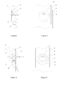
- Figure 1 shows a coupling structure of a water-manifold to a generator housing in an electric machine.
- the water-manifold has a ring shape with several coupling plates over the ring.
- the housing is shown in partial with several plates to be connected to the coupling plates of the water-manifold.
- this coupling structure several pairs of coupling plates will be joined by bolts, which requires all the bolt holes to be aligned at the same time. This requires a high machining precision of the holes as a machining error of one hole may cause accumulation errors so that the alignment of all the holes cannot be achieved.
- FIG. 1 Another example of a coupling structure is applied to fix a machine foundation.
- a plurality of anchor bolts are used to fix a machine foundation to some place, which also requires all the corresponding coupling parts to be aligned at the same time before inserting the bolts.
- the current coupling structure especially with a plurality of coupling parts, has higher requirements for machining and also assembling of the relevant coupling parts, which increases the cost and time of machining and assembling.
- An aspect of the disclosure includes providing a coupling structure with aligners to connect coupling parts, which gives flexibility to assemble the coupling parts and thus reduces the machining and assembling difficulty of the coupling parts.
- Another aspect of the disclosure provides a method to connect coupling parts with aligners.
- a first coupling part 2 is joined with a second coupling part 3 through a first circular element 1 and a bolt.
- the second coupling part 3 has a bolt hole to receive the bolt; the first coupling part 2 has a hole 5 bigger than the bolt hole to receive the first circular element 1.
- the first circular element 1 has an eccentric hole 6 and a circular step. Since the hole 6 is eccentrically provided in the first circular element 1, the position of the hole 6 can be adjusted around the central line of the first circular element 1 by rotating the first circular element 1 in the hole 5. When the hole 6 is adjusted to align with the bolt hole in the second coupling part 3, the bolt can be inserted. The step of the first circular element 1 abuts on the first coupling part 2 and fastens the first and second coupling part as the bolt is tightened.
- Figure 3 is a side view of Figure 2 with the bolt removed. As shown in Figure 3 , the eccentric circle 6 can be adjusted around the centre of the first circular element 1.
- the above coupling structure gives flexibility on adjustment to allow machining and assembling errors of the coupling parts to certain extent.
- Figure 4 illustrates the second embodiment of the disclosure that is similar to the first embodiment. The description of the similar parts is omitted. The difference is that a second circular element 4 is applied to give more flexibility.
- the first circular element 1 has an eccentric hole 6 to receive a second circular element 4.
- the second circular element 4 has an eccentric hole 7 to receive the bolt.
- the second circular element 4 is also provided with a circular step.
- the first circular element 1 and the second circular element 4 are rotated around their respective central line to align the hole 7 with the bolt hole in the second coupling part 3. Then the bolt is inserted and the step of the second circular element 4 abuts on the first circular element 1 and fastens the first circular element 1 as well as the first and second coupling part as the bolt is tightened.
- Figure 5 is a side view of Figure 4 with the bolt removed.
- the eccentric hole 7 can be adjusted through the rotation of the first circular element 1 and the second circular element 4.
- the coupling structure in the second embodiment provides more flexibility on adjustment to allow machining and assembling errors of the coupling parts.
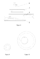
- Figures 6-8 show the variants of the second embodiment of the disclosure.
- the circumferential surface of the first circular element 1 can be machined to a slope to form inference fit within the first coupling part 2.
- the circumferential surface of the second circular element 4 can be machined to a slope to form inference fit within the first circular element 1.
- the slopes can be formed in the surface of the hole in the first circular element 1 and the first coupling part 2.
- a preferred slope angle is between 0.1° - 10° depending on the thickness and material properties of the coupling parts.
- the first circular element 1 adopts the "step” form and the second circular element 4 adopts the "slope” form.
- the "step” form in the second circular element 4 and adopt the "slope” form in the first circular element 1.
- Figure 8 shows another variant of the second embodiment
- Figure 9 shows the plan view of the second circular element 4 of Figure 8 with the bolt removed
- Figure 10 shows the plan view of the first circular element 1 of Figure 8 .
- the second circular element 4 is formed with a plurality of radial protrusions along its circumference.
- the first circular element 1 has the same number of radial inner protrusions along the hole surface complementary to the protrusions in the second circular element 4.
- the holes in the first and second circular element are eccentric.
- the first circular element 1 is provided with a step along its circumference. Instead of the step, it is also possible to form slope either in the circumferential surface of the first circular element 1 or the hole surface of the first coupling part 2.
- the second circular element 4 can be placed into the first circular element 1 when the protrusions of the two elements are in complementary state. Then, when rotated, the second circular element 4 can be locked in the first circular element 1 in the axial direction by the opposite protrusions of the two elements. Through the rotation of the first circular element 1 and the second circular element 4, the holes can be aligned and then a bolt is inserted to fasten the connection of two coupling parts.
- the coupling structure as described in the above embodiments can be applied in any misaligned assembly, including but not limited to generator or motor foundation coupling, the coupling between turbine and generator, and various covers within a machine.
Landscapes
- Engineering & Computer Science (AREA)
- General Engineering & Computer Science (AREA)
- Mechanical Engineering (AREA)
- Connection Of Plates (AREA)
Abstract
Description
- The present disclosure relates to a coupling structure, more particularly, it relates to a coupling structure with aligners to connect coupling parts. The present disclosure also relates to a method to connect coupling parts with aligners.
- It is common to apply bolts or rivets and the like to connect two coupling parts in a machine. In many cases, the connection of two coupling parts needs a plurality of bolts. For example,
Figure 1 shows a coupling structure of a water-manifold to a generator housing in an electric machine. The water-manifold has a ring shape with several coupling plates over the ring. The housing is shown in partial with several plates to be connected to the coupling plates of the water-manifold. In this coupling structure, several pairs of coupling plates will be joined by bolts, which requires all the bolt holes to be aligned at the same time. This requires a high machining precision of the holes as a machining error of one hole may cause accumulation errors so that the alignment of all the holes cannot be achieved. - Another example of a coupling structure is applied to fix a machine foundation. In this case, a plurality of anchor bolts are used to fix a machine foundation to some place, which also requires all the corresponding coupling parts to be aligned at the same time before inserting the bolts.
- Therefore, the current coupling structure, especially with a plurality of coupling parts, has higher requirements for machining and also assembling of the relevant coupling parts, which increases the cost and time of machining and assembling.
- An aspect of the disclosure includes providing a coupling structure with aligners to connect coupling parts, which gives flexibility to assemble the coupling parts and thus reduces the machining and assembling difficulty of the coupling parts.
- Another aspect of the disclosure provides a method to connect coupling parts with aligners.
- These and further aspects are attained by providing a coupling structure and a method in accordance with the accompanying claims.
- Further characteristics and advantages will be more apparent from the description of a preferred but non-exclusive embodiment of the coupling structure and method, illustrated by way of non-limiting example in the accompanying drawings, in which:
-
Figure 1 is a schematic view of a coupling structure of several coupling parts according to the prior art; -
Figure 2 is a section view showing the coupling structure according to the first embodiment of the disclosure; -
Figure 3 is a side view of the coupling structure ofFigure 2 ; -
Figure 4 is a section view showing the coupling structure according to the second embodiment of the disclosure; -
Figure 5 is a side view of the coupling structure ofFigure 4 ; -
Figures 6 through 8 are schematic views showing the variants of the second embodiment of the disclosure; -
Figure 9 is a plan view of thepart 4 offigure 8 ; and -
Figure 10 is a plan view of thepart 1 offigure 8 . - In the following like reference numerals designate identical or corresponding parts throughout the several views.
- In the first embodiment of the disclosure as shown in
Figure 2 , afirst coupling part 2 is joined with asecond coupling part 3 through a firstcircular element 1 and a bolt. Thesecond coupling part 3 has a bolt hole to receive the bolt; thefirst coupling part 2 has ahole 5 bigger than the bolt hole to receive the firstcircular element 1. The firstcircular element 1 has aneccentric hole 6 and a circular step. Since thehole 6 is eccentrically provided in the firstcircular element 1, the position of thehole 6 can be adjusted around the central line of the firstcircular element 1 by rotating the firstcircular element 1 in thehole 5. When thehole 6 is adjusted to align with the bolt hole in thesecond coupling part 3, the bolt can be inserted. The step of the firstcircular element 1 abuts on thefirst coupling part 2 and fastens the first and second coupling part as the bolt is tightened. -
Figure 3 is a side view ofFigure 2 with the bolt removed. As shown inFigure 3 , theeccentric circle 6 can be adjusted around the centre of the firstcircular element 1. - The above coupling structure gives flexibility on adjustment to allow machining and assembling errors of the coupling parts to certain extent.
-
Figure 4 illustrates the second embodiment of the disclosure that is similar to the first embodiment. The description of the similar parts is omitted. The difference is that a secondcircular element 4 is applied to give more flexibility. In particular, the firstcircular element 1 has aneccentric hole 6 to receive a secondcircular element 4. The secondcircular element 4 has aneccentric hole 7 to receive the bolt. The secondcircular element 4 is also provided with a circular step. - Before inserting the bolt, the first
circular element 1 and the secondcircular element 4 are rotated around their respective central line to align thehole 7 with the bolt hole in thesecond coupling part 3. Then the bolt is inserted and the step of the secondcircular element 4 abuts on the firstcircular element 1 and fastens the firstcircular element 1 as well as the first and second coupling part as the bolt is tightened. -
Figure 5 is a side view ofFigure 4 with the bolt removed. Theeccentric hole 7 can be adjusted through the rotation of the firstcircular element 1 and the secondcircular element 4. With two circular elements having eccentric holes therein, the coupling structure in the second embodiment provides more flexibility on adjustment to allow machining and assembling errors of the coupling parts. -
Figures 6-8 show the variants of the second embodiment of the disclosure. - In
Figure 6 , instead of the step formed on the firstcircular element 1, the circumferential surface of the firstcircular element 1 can be machined to a slope to form inference fit within thefirst coupling part 2. Similarly, the circumferential surface of the secondcircular element 4 can be machined to a slope to form inference fit within the firstcircular element 1. When the first and second circular elements are rotated to an appropriate position so that the holes are aligned, both elements are pressed into the corresponding holes and tightened in inference fit. Then the bolt can be inserted to connect the coupling parts. - Further, instead of being formed on the circumferential surface of the first and second circular elements as shown in
Figure 6 , the slopes can be formed in the surface of the hole in the firstcircular element 1 and thefirst coupling part 2. - A preferred slope angle is between 0.1° - 10° depending on the thickness and material properties of the coupling parts.
- It is noted that this "slope" form can also be applied in the first embodiment instead of the "step" form.
- In
Figure 7 , the firstcircular element 1 adopts the "step" form and the secondcircular element 4 adopts the "slope" form. Of course, it is also possible to adopt the "step" form in the secondcircular element 4 and adopt the "slope" form in the firstcircular element 1. -
Figure 8 shows another variant of the second embodiment;Figure 9 shows the plan view of the secondcircular element 4 ofFigure 8 with the bolt removed;Figure 10 shows the plan view of the firstcircular element 1 ofFigure 8 . - In this variant, the second
circular element 4 is formed with a plurality of radial protrusions along its circumference. Correspondingly, the firstcircular element 1 has the same number of radial inner protrusions along the hole surface complementary to the protrusions in the secondcircular element 4. The holes in the first and second circular element are eccentric. The firstcircular element 1 is provided with a step along its circumference. Instead of the step, it is also possible to form slope either in the circumferential surface of the firstcircular element 1 or the hole surface of thefirst coupling part 2. - The second
circular element 4 can be placed into the firstcircular element 1 when the protrusions of the two elements are in complementary state. Then, when rotated, the secondcircular element 4 can be locked in the firstcircular element 1 in the axial direction by the opposite protrusions of the two elements. Through the rotation of the firstcircular element 1 and the secondcircular element 4, the holes can be aligned and then a bolt is inserted to fasten the connection of two coupling parts. - The coupling structure as described in the above embodiments can be applied in any misaligned assembly, including but not limited to generator or motor foundation coupling, the coupling between turbine and generator, and various covers within a machine.
- Naturally the features described may be independently provided from one another.
- The embodiments conceived in this manner are susceptible to numerous modifications and variants, all falling within the scope of the inventive concept; moreover all details can be replaced by technically equivalent elements.
- In practice the materials used and the dimensions can be chosen at will according to requirements and to the state of the art.
-
- 1
- first circular element
- 2
- first coupling part
- 3
- second coupling part
- 4
- second circular element
- 5
- hole of first coupling part
- 6
- first eccentric hole
- 7
- second eccentric hole
Claims (12)
- A coupling structure comprising coupling parts and at least an aligner to connect the coupling parts, characterised in that the aligner comprises a first circular element (1) with a first eccentric hole (6) and is contained in a hole (5) of a first coupling part (2).
- The coupling structure according to claim 1, characterised in that the first circular element (1) comprises a circular step to abut on the first coupling part (2).
- The coupling structure according to claim 1, characterised in that either the circumferential surface of the first circular element (1) or the surface of the hole (5) of the first coupling part (2) is a slope to form interference fit between the first circular element (1) and the first coupling part (2).
- The coupling structure according to claim 1, characterised in that the aligner further comprises a second circular element (4) with a second eccentric hole (7), the second circular element (4) being contained in the first eccentric hole (6) of the first circular element (1).
- The coupling structure according to claim 4, characterised in that the first circular element (1) comprises a circular step to abut on the first coupling part (2).
- The coupling structure according to claim 4 or 5, characterised in that the second circular element (4) comprises a circular step to abut on the first circular element (1).
- The coupling structure according to claim 4, characterised in that either the circumferential surface of the first circular element (1) or the surface of the hole (5) of the first coupling part (2) is a slope to form interference fit between the first circular element (1) and the first coupling part (2).
- The coupling structure according to claim 4 or 5, characterised in that either the circumferential surface of the second circular element (4) or the surface of the first eccentric hole (6) of the first circular element (1) is a slope to form interference fit between the first circular element (1) and the second circular element (4).
- The coupling structure according to claim 5 or 7, characterised in that the first circular element (1) further comprises a plurality of radial inner protrusions, the second circular element (4) comprises a plurality of radial outer protrusions complementary to the inner protrusions of the first circular element (1).
- The coupling structure according to claim 1, characterised in that the coupling parts (2) belong to an electric machine, preferably an electric generator, more preferably a water-manifold of an electric generator.
- A method for connecting coupling parts through an aligner that comprises a first circular element (1) having a first eccentric hole (6) and being contained in a hole (5) of a first coupling part (2);
the method being characterised by
rotating the first circular element (1) to align the first eccentric hole (6) to a hole in a second coupling part (3),
inserting a bolt to connect the first coupling part (2) and the second coupling part (3). - The method according to claim 11, wherein the aligner further comprises a second circular element (4) with a second eccentric hole (7), the second circular element (4) being contained in the first eccentric hole (6) of the first circular element (1),
the method being characterised by
rotating the second circular element (4) to align the second eccentric hole (7) to the hole in the second coupling part (3) before inserting the bolt.
Priority Applications (1)
| Application Number | Priority Date | Filing Date | Title |
|---|---|---|---|
| EP12160202.3A EP2642136A1 (en) | 2012-03-19 | 2012-03-19 | Coupling structure and method to connect coupling parts |
Applications Claiming Priority (1)
| Application Number | Priority Date | Filing Date | Title |
|---|---|---|---|
| EP12160202.3A EP2642136A1 (en) | 2012-03-19 | 2012-03-19 | Coupling structure and method to connect coupling parts |
Publications (1)
| Publication Number | Publication Date |
|---|---|
| EP2642136A1 true EP2642136A1 (en) | 2013-09-25 |
Family
ID=45936833
Family Applications (1)
| Application Number | Title | Priority Date | Filing Date |
|---|---|---|---|
| EP12160202.3A Withdrawn EP2642136A1 (en) | 2012-03-19 | 2012-03-19 | Coupling structure and method to connect coupling parts |
Country Status (1)
| Country | Link |
|---|---|
| EP (1) | EP2642136A1 (en) |
Cited By (3)
| Publication number | Priority date | Publication date | Assignee | Title |
|---|---|---|---|---|
| CN109571356A (en) * | 2018-12-29 | 2019-04-05 | 昆山文刀精工机械科技有限公司 | A kind of hole heart adjustment structure, the sub-assembly using the structure and connection method |
| US20220381273A1 (en) * | 2021-05-28 | 2022-12-01 | Airbus Operations Sas | Double eccentric type connection assembly comprising a ring made of deformable material for a connection between two structures of an aircraft, and aircraft comprising such an assembly |
| FR3163418A1 (en) * | 2024-06-17 | 2025-12-19 | Stellantis Auto Sas | Adjustable center distance brake drum |
Citations (4)
| Publication number | Priority date | Publication date | Assignee | Title |
|---|---|---|---|---|
| US4097168A (en) * | 1975-09-24 | 1978-06-27 | Microdot Inc. | Prestressed connection and fastener therefor |
| US20020133950A1 (en) * | 2001-03-26 | 2002-09-26 | Lockheed Martin Corporation | Hole misalignment compensation system and method |
| FR2882967A3 (en) * | 2005-03-08 | 2006-09-15 | Hung Chuan Wu | Washer for vehicle components has round washer body formed with expansion and insertion portions of different diameters and placed into assembly hole of vehicle component to change pitch center diameter of component |
| EP1860334A1 (en) * | 2006-05-23 | 2007-11-28 | ABB Schweiz AG | Countersunk spring nut device and electrical connection with such a device |
-
2012
- 2012-03-19 EP EP12160202.3A patent/EP2642136A1/en not_active Withdrawn
Patent Citations (4)
| Publication number | Priority date | Publication date | Assignee | Title |
|---|---|---|---|---|
| US4097168A (en) * | 1975-09-24 | 1978-06-27 | Microdot Inc. | Prestressed connection and fastener therefor |
| US20020133950A1 (en) * | 2001-03-26 | 2002-09-26 | Lockheed Martin Corporation | Hole misalignment compensation system and method |
| FR2882967A3 (en) * | 2005-03-08 | 2006-09-15 | Hung Chuan Wu | Washer for vehicle components has round washer body formed with expansion and insertion portions of different diameters and placed into assembly hole of vehicle component to change pitch center diameter of component |
| EP1860334A1 (en) * | 2006-05-23 | 2007-11-28 | ABB Schweiz AG | Countersunk spring nut device and electrical connection with such a device |
Cited By (4)
| Publication number | Priority date | Publication date | Assignee | Title |
|---|---|---|---|---|
| CN109571356A (en) * | 2018-12-29 | 2019-04-05 | 昆山文刀精工机械科技有限公司 | A kind of hole heart adjustment structure, the sub-assembly using the structure and connection method |
| CN109571356B (en) * | 2018-12-29 | 2023-11-24 | 昆山文刀精工机械科技有限公司 | Hole core adjusting structure, assembly using same and connecting method |
| US20220381273A1 (en) * | 2021-05-28 | 2022-12-01 | Airbus Operations Sas | Double eccentric type connection assembly comprising a ring made of deformable material for a connection between two structures of an aircraft, and aircraft comprising such an assembly |
| FR3163418A1 (en) * | 2024-06-17 | 2025-12-19 | Stellantis Auto Sas | Adjustable center distance brake drum |
Similar Documents
| Publication | Publication Date | Title |
|---|---|---|
| US6481969B2 (en) | Apparatus and methods for balancing turbine rotors | |
| US6552459B2 (en) | Permanent magnet rotor design | |
| RU2658661C1 (en) | Rotating electric rotor and rotating electric rotor manufacturing method | |
| US11159066B2 (en) | Rotary electric machine and rotor mounted therein | |
| US8810100B2 (en) | Rotor having dividable core for electric motor and production method thereof | |
| KR20140133543A (en) | Turbine generator stator core attachment technique | |
| KR20140105854A (en) | Rotor blade set of an electric motor | |
| JPH0757073B2 (en) | Electric equipment iron core support device and electric equipment iron core assembly device | |
| US10563541B2 (en) | Securing device, steam turbine, and rotary machine manufacturing method and assembly method | |
| WO2013097981A2 (en) | Device for retaining a machine component in an electric machine and electric machine | |
| JP2014031872A (en) | Rotor connecting jig for rotary machine, and rotor connecting method | |
| JP7309925B2 (en) | Hybrid modular transport strap | |
| US11916441B2 (en) | Rotor for an electric machine | |
| EP2383468A1 (en) | System and method for connecting shafts of a wind turbine | |
| US12237722B2 (en) | Laminated rotor core for a rotor, and method for producing a laminated rotor core | |
| US11777345B2 (en) | Securing of stator segments | |
| TW201420844A (en) | Pileless joint | |
| JP2007116886A (en) | Iron core for rotating electrical machine and method for assembling the same | |
| KR20120061921A (en) | Gear wheel | |
| EP3765715B1 (en) | Locking spacer assembly, blade assembly and method for installing a locking spacer | |
| KR100590972B1 (en) | Multi-ring terminal structure for earth | |
| CN104675959A (en) | Transmission pulley, method for producing such a pulley, and power transmission system comprising such a pulley | |
| JP5696642B2 (en) | Stator fixing structure | |
| KR102219323B1 (en) | Fixed structure of spiral wind turbine blade | |
| US20190173331A1 (en) | Motor and stator crush resistance device |
Legal Events
| Date | Code | Title | Description |
|---|---|---|---|
| PUAI | Public reference made under article 153(3) epc to a published international application that has entered the european phase |
Free format text: ORIGINAL CODE: 0009012 |
|
| AK | Designated contracting states |
Kind code of ref document: A1 Designated state(s): AL AT BE BG CH CY CZ DE DK EE ES FI FR GB GR HR HU IE IS IT LI LT LU LV MC MK MT NL NO PL PT RO RS SE SI SK SM TR |
|
| AX | Request for extension of the european patent |
Extension state: BA ME |
|
| STAA | Information on the status of an ep patent application or granted ep patent |
Free format text: STATUS: THE APPLICATION HAS BEEN WITHDRAWN |
|
| 18W | Application withdrawn |
Effective date: 20131030 |
|
| RIN1 | Information on inventor provided before grant (corrected) |
Inventor name: NOVOSEL, DAMIR Inventor name: SAFARI ZADEH, IMMANUEL |
|
| RIN1 | Information on inventor provided before grant (corrected) |
Inventor name: NOVOSEL, DAMIR Inventor name: SAFARI ZADEH, HOSSEIN |