EP2642029A1 - Revolving stage buffer device of strong rammer compactor - Google Patents
Revolving stage buffer device of strong rammer compactor Download PDFInfo
- Publication number
- EP2642029A1 EP2642029A1 EP11773166.1A EP11773166A EP2642029A1 EP 2642029 A1 EP2642029 A1 EP 2642029A1 EP 11773166 A EP11773166 A EP 11773166A EP 2642029 A1 EP2642029 A1 EP 2642029A1
- Authority
- EP
- European Patent Office
- Prior art keywords
- chassis
- slewing
- platform
- tamping machine
- hydraulic cylinder
- Prior art date
- Legal status (The legal status is an assumption and is not a legal conclusion. Google has not performed a legal analysis and makes no representation as to the accuracy of the status listed.)
- Granted
Links
Images

Classifications
-
- E—FIXED CONSTRUCTIONS
- E02—HYDRAULIC ENGINEERING; FOUNDATIONS; SOIL SHIFTING
- E02D—FOUNDATIONS; EXCAVATIONS; EMBANKMENTS; UNDERGROUND OR UNDERWATER STRUCTURES
- E02D3/00—Improving or preserving soil or rock, e.g. preserving permafrost soil
- E02D3/02—Improving by compacting
- E02D3/046—Improving by compacting by tamping or vibrating, e.g. with auxiliary watering of the soil
-
- E—FIXED CONSTRUCTIONS
- E01—CONSTRUCTION OF ROADS, RAILWAYS, OR BRIDGES
- E01C—CONSTRUCTION OF, OR SURFACES FOR, ROADS, SPORTS GROUNDS, OR THE LIKE; MACHINES OR AUXILIARY TOOLS FOR CONSTRUCTION OR REPAIR
- E01C19/00—Machines, tools or auxiliary devices for preparing or distributing paving materials, for working the placed materials, or for forming, consolidating, or finishing the paving
- E01C19/22—Machines, tools or auxiliary devices for preparing or distributing paving materials, for working the placed materials, or for forming, consolidating, or finishing the paving for consolidating or finishing laid-down unset materials
- E01C19/30—Tamping or vibrating apparatus other than rollers ; Devices for ramming individual paving elements
-
- E—FIXED CONSTRUCTIONS
- E01—CONSTRUCTION OF ROADS, RAILWAYS, OR BRIDGES
- E01C—CONSTRUCTION OF, OR SURFACES FOR, ROADS, SPORTS GROUNDS, OR THE LIKE; MACHINES OR AUXILIARY TOOLS FOR CONSTRUCTION OR REPAIR
- E01C19/00—Machines, tools or auxiliary devices for preparing or distributing paving materials, for working the placed materials, or for forming, consolidating, or finishing the paving
- E01C19/22—Machines, tools or auxiliary devices for preparing or distributing paving materials, for working the placed materials, or for forming, consolidating, or finishing the paving for consolidating or finishing laid-down unset materials
- E01C19/30—Tamping or vibrating apparatus other than rollers ; Devices for ramming individual paving elements
- E01C19/34—Power-driven rammers or tampers, e.g. air-hammer impacted shoes for ramming stone-sett paving; Hand-actuated ramming or tamping machines, e.g. tampers with manually hoisted dropping weight
-
- E—FIXED CONSTRUCTIONS
- E02—HYDRAULIC ENGINEERING; FOUNDATIONS; SOIL SHIFTING
- E02D—FOUNDATIONS; EXCAVATIONS; EMBANKMENTS; UNDERGROUND OR UNDERWATER STRUCTURES
- E02D3/00—Improving or preserving soil or rock, e.g. preserving permafrost soil
- E02D3/02—Improving by compacting
- E02D3/046—Improving by compacting by tamping or vibrating, e.g. with auxiliary watering of the soil
- E02D3/054—Improving by compacting by tamping or vibrating, e.g. with auxiliary watering of the soil involving penetration of the soil, e.g. vibroflotation
-
- F—MECHANICAL ENGINEERING; LIGHTING; HEATING; WEAPONS; BLASTING
- F16—ENGINEERING ELEMENTS AND UNITS; GENERAL MEASURES FOR PRODUCING AND MAINTAINING EFFECTIVE FUNCTIONING OF MACHINES OR INSTALLATIONS; THERMAL INSULATION IN GENERAL
- F16C—SHAFTS; FLEXIBLE SHAFTS; ELEMENTS OR CRANKSHAFT MECHANISMS; ROTARY BODIES OTHER THAN GEARING ELEMENTS; BEARINGS
- F16C2300/00—Application independent of particular apparatuses
- F16C2300/10—Application independent of particular apparatuses related to size
- F16C2300/14—Large applications, e.g. bearings having an inner diameter exceeding 500 mm
-
- F—MECHANICAL ENGINEERING; LIGHTING; HEATING; WEAPONS; BLASTING
- F16—ENGINEERING ELEMENTS AND UNITS; GENERAL MEASURES FOR PRODUCING AND MAINTAINING EFFECTIVE FUNCTIONING OF MACHINES OR INSTALLATIONS; THERMAL INSULATION IN GENERAL
- F16C—SHAFTS; FLEXIBLE SHAFTS; ELEMENTS OR CRANKSHAFT MECHANISMS; ROTARY BODIES OTHER THAN GEARING ELEMENTS; BEARINGS
- F16C2350/00—Machines or articles related to building
-
- F—MECHANICAL ENGINEERING; LIGHTING; HEATING; WEAPONS; BLASTING
- F16—ENGINEERING ELEMENTS AND UNITS; GENERAL MEASURES FOR PRODUCING AND MAINTAINING EFFECTIVE FUNCTIONING OF MACHINES OR INSTALLATIONS; THERMAL INSULATION IN GENERAL
- F16C—SHAFTS; FLEXIBLE SHAFTS; ELEMENTS OR CRANKSHAFT MECHANISMS; ROTARY BODIES OTHER THAN GEARING ELEMENTS; BEARINGS
- F16C35/00—Rigid support of bearing units; Housings, e.g. caps, covers
- F16C35/04—Rigid support of bearing units; Housings, e.g. caps, covers in the case of ball or roller bearings
- F16C35/06—Mounting or dismounting of ball or roller bearings; Fixing them onto shaft or in housing
Definitions
- the present invention relates to a tamping machine, and specifically relates to a buffer unit for the slewing platform of a tamping machine.
- Chinese utility model patent CN261124Y provided a crawler-type tamping machine with a hydraulic cylinder and solved the above mentioned problem in part.
- its hydraulic cylinder could not touch and support the chassis annular at any point of direction of 360 degrees, and its working position is only forwards, backwards, right and left, which is inconvenient when working in all directions.
- Such shortcomings result in the low working effectiveness of the tamping machine.
- the tamping machine In order to adapt to different problems during building operations, the tamping machine needs to adjust the working position as is the case, so it is necessary to provide a buffer unit which could rotate 360 degrees in all directions, for the crawler-type tamping machine, frees the crawler-type tamping machine from the limitation of the prior working position, and ensures the tamping machine working free from the rough road conditions.
- the purpose of the present utility model is to provide a buffer unit for the slewing platform of a tamping machine, which comprises a slewing bearing and a chassis, the upper end of the said slewing bearing connects to the slewing platform and the lower end of the said slewing bearing connects to the chassis, the said slewing platform can revolve around the chassis 360 degrees, and further comprising an annular supporting slab, a hydraulic cylinder and a connecting rod, the said annular supporting slab being fixed on the chassis by bolts.
- the said hydraulic cylinder is fitted on the rear end of the central plane of the slewing platform, the piston rod head of the hydraulic cylinder connects to the said connecting rod.
- the said buffer unit for the slewing platform of a tamping machine wherein the difference in height between the said slewing platform and the said chassis meets the requirements that the said connecting rod touches and supports the annular supporting slab at any point of direction of 360 degrees rotation when the hydraulic cylinder extends.
- the said buffer unit for the slewing platform of a tamping machine wherein the annular supporting slab is an annular metal plate, the width of the said annular metal plate being longer than the length of the diameter of the said connecting rod.
- the said buffer unit for the slewing platform of a tamping machine wherein the chassis comprises an "H" shaped bracket, the said annular supporting slab comprising two retaining plates separately fixed on the two brackets of the said chassis and two active plates separately fixed between two brackets of the said chassis, the four plates being distributed in circular form.
- the said buffer unit for the slewing platform of a tamping machine wherein a groove is formed on the internal surface of the said retaining plate, which forms a guide rail with two legs of the chassis, so that the active plates could extend in the guide surface to adjust the position to change the radius of the retaining plates.
- the said buffer unit for the slewing platform of a tamping machine wherein the active plate is supported by four legs, the said legs connect to the said chassis with a hinge pin, and the said supporting legs could revolve around the said hinge pin.
- the said buffer unit for the slewing platform of a tamping machine wherein the chassis comprises several mounting holes, the bolts which connect to the said active plate and the said chassis are fixed in different mounting holes selectively.
- the detailed description of the buffer unit for the slewing platform of the tamping machine of the present embodiment is as following.
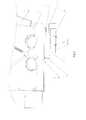
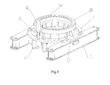
- Figure 1 and Figure 2 show the structure diagram of the buffer unit for the slewing platform of the tamping machine of the present utility model.
- the said buffer unit for the slewing platform 2 of the tamping machine comprises a slewing bearing 3, a leg 4, a chassis 5, an annular supporting slab, a hydraulic cylinder 8 and a connecting rod 9.
- the slewing bearing 3 comprises the outboard wheel 301 and inboard wheel 302.
- the outboard wheel 301 and the inboard wheel 302 have several mounting holes for fixing the connecting piece of the slewing bearing 3, the outboard wheel 301 is fixed on the mounting hole by bolts to connect with the slewing platform 2, the inboard wheel 302 is fixed on the mounting hole by bolts to connect to the chassis 5, so the slewing platform 2 could revolve around the chassis 5 through 360 degrees.
- the annular supporting slab is positioned around the chassis 5, and is fixed on the chassis 5 by bolts and centers around the slewing bearing 3.
- the said leg 4 is fitted on the chassis 5 by bolts, the other end of the said leg supports the annular supporting slab.
- the hydraulic cylinder 8 is fitted on the rear end of the central plane of the platform, the piston rod head of the hydraulic cylinder 8 connects to the said connecting rod 9.
- the difference in height between the platform 2 and the chassis 5 meet the requirements that the connecting rod 9 touches and supports the annular supporting slab at any point of direction of 360 degree rotation when the hydraulic cylinder 8 extends.
- the said annular supporting slab comprises two retaining plates 6 and two active plates 7.
- the chassis 5 comprises an "H" shaped bracket, the two retaining plates 6 are separately fixed on two brackets of the chassis 5, the two active plates 7 are separately fitted between two brackets of the chassis, and the two retaining plates 6 and the two active plates 7 are distributed in circular form.
- the width of the retaining plates 6 equals the width of the active plates 7, so that the connecting rod 9 could support at any position of the retaining plates 6 or the active plates 7.
- the pounder of the tamping machine falls down, thus generating rebound to the arm support 1, and the hydraulic cylinder 8 provides a load shedding effect, the connecting rod 9, which connects to the piston head, support the annular supporting slab when the hydraulic cylinder 8 extends, and provides a buffer for the slewing platform 2 of the tamping machine, to protect the slewing bearing.
- the piston of the hydraulic cylinder 8 retracts automatically to maintain the balance of pressure between the internal and external, the connecting rod 9 which connects to the piston raises with the piston and breaks away from the annular supporting slab to make the said slewing platform avoid a limitation when it carries on platform revolution working.
- the piston of the hydraulic cylinder 8 pushes the connecting rod 9 to support the annular supporting slab at another position, so that the buffer unit for the slewing platform of the tamping machine could act as a buffer at any position of 360 degrees.
- FIG. 3 shows a top view of the buffer unit for the slewing platform of the tamping machine.
- the buffer unit comprises the chassis 5, the left retaining plate 601, the right retaining plate 602, the forward active plate 701, the backward active plate 702 and the legs 401, 402, 403, 404 in detail, wherein the said four legs are fitted on the chassis 5 by a hinge pin under the mounting position of the active plate.
- the two "H" shaped brackets of the chassis 5 have two rows of mounting holes, the left retaining plate 601 and right retaining plate 602 are fitted on the two outboard mounting holes by bolts, to make the retaining plate fixed on the chassis 5; two ends of the forward active plate 701 and backward active plate 702 both have through-holes, the chassis 5 has four vertical mounting holes for selecting the mounting position of the active plate.
- the forward active plate 701 is fitted on the inside position close to the chassis 5 by bolts
- the backward active plate 702 is fitted on the outermost mounting hole by bolts, and form a half ring with the retaining plate 601 and 602.
- the legs 401, 402 support the forward active plate 701
- the legs 403, 404 support the backward active plate 702. Accordingly, the legs 401,402 fix and revolve around the bracket of chassis 5 by 90 degree by hinge pin, to ensure it could touch the said forward active plate 701, the legs 403, 404 keep parallel with the bracket of the chassis 5 to support the backward active plate 702, which is far away from the centre of chassis 5.
- different amounts of mounting holes are processed in the chassis 5 to provide the forward active plate 701 and the backward active plate 702 a bigger or smaller adjustable scope.
- the said left retaining plate 601 and right retaining plate 602 are fixed on the chassis 5 by welding.
Landscapes
- Engineering & Computer Science (AREA)
- Structural Engineering (AREA)
- Life Sciences & Earth Sciences (AREA)
- Civil Engineering (AREA)
- Environmental & Geological Engineering (AREA)
- Agronomy & Crop Science (AREA)
- Architecture (AREA)
- Soil Sciences (AREA)
- General Life Sciences & Earth Sciences (AREA)
- Mining & Mineral Resources (AREA)
- Paleontology (AREA)
- General Engineering & Computer Science (AREA)
- Machines For Laying And Maintaining Railways (AREA)
- Investigation Of Foundation Soil And Reinforcement Of Foundation Soil By Compacting Or Drainage (AREA)
- Shovels (AREA)
Abstract
Description
- The present invention relates to a tamping machine, and specifically relates to a buffer unit for the slewing platform of a tamping machine.
- When a tamping machine is running, the pounder falls down, thus generating rebounce to the arm support. In a crawler-type tamping machine, due to its slewing platform being connected to the chassis with a slewing bearing, the rebounce would produce impact force to the slewing bearing.
- Chinese utility model patent
CN261124Y provided a crawler-type tamping machine with a hydraulic cylinder and solved the above mentioned problem in part. However, its hydraulic cylinder could not touch and support the chassis annular at any point of direction of 360 degrees, and its working position is only forwards, backwards, right and left, which is inconvenient when working in all directions. Such shortcomings result in the low working effectiveness of the tamping machine. - In order to adapt to different problems during building operations, the tamping machine needs to adjust the working position as is the case, so it is necessary to provide a buffer unit which could rotate 360 degrees in all directions, for the crawler-type tamping machine, frees the crawler-type tamping machine from the limitation of the prior working position, and ensures the tamping machine working free from the rough road conditions.
- Aiming at the defect of the prior art, the purpose of the present utility model is to provide a buffer unit for the slewing platform of a tamping machine, which comprises a slewing bearing and a chassis, the upper end of the said slewing bearing connects to the slewing platform and the lower end of the said slewing bearing connects to the chassis, the said slewing platform can revolve around the chassis 360 degrees, and further comprising an annular supporting slab, a hydraulic cylinder and a connecting rod, the said annular supporting slab being fixed on the chassis by bolts. The said hydraulic cylinder is fitted on the rear end of the central plane of the slewing platform, the piston rod head of the hydraulic cylinder connects to the said connecting rod.
- The said buffer unit for the slewing platform of a tamping machine, wherein the difference in height between the said slewing platform and the said chassis meets the requirements that the said connecting rod touches and supports the annular supporting slab at any point of direction of 360 degrees rotation when the hydraulic cylinder extends.
- The said buffer unit for the slewing platform of a tamping machine, wherein the annular supporting slab is an annular metal plate, the width of the said annular metal plate being longer than the length of the diameter of the said connecting rod.
- The said buffer unit for the slewing platform of a tamping machine, wherein the chassis comprises an "H" shaped bracket, the said annular supporting slab comprising two retaining plates separately fixed on the two brackets of the said chassis and two active plates separately fixed between two brackets of the said chassis, the four plates being distributed in circular form.
- The said buffer unit for the slewing platform of a tamping machine, wherein a groove is formed on the internal surface of the said retaining plate, which forms a guide rail with two legs of the chassis, so that the active plates could extend in the guide surface to adjust the position to change the radius of the retaining plates.
- The said buffer unit for the slewing platform of a tamping machine, wherein the active plate is supported by four legs, the said legs connect to the said chassis with a hinge pin, and the said supporting legs could revolve around the said hinge pin.
- The said buffer unit for the slewing platform of a tamping machine, wherein the chassis comprises several mounting holes, the bolts which connect to the said active plate and the said chassis are fixed in different mounting holes selectively.
- The benefits of the utility model are as following:
- 1. Stability: the reduction of loading of the hydraulic cylinder acts as dampening effect to the slewing platform and avoids it tipping over, and acts as protective effect to the slewing bearing, protects it from the frequent impact force, so that increases stability and reliability of the unit.
- 2. Applicability: The slewing platform could be protected at any working position of 360 degrees by configuring the annular supporting slab.
- 3. The hydraulic cylinder is positioned on the chassis instead of on the ground, which ensures the tamping machine working free from the rough road conditions.
- With reference to the following figures and the detailed description given by way of example, other features, objectives and advantages of the utility model will become apparent:
-
Figure 1 shows side view of the buffer unit for the slewing platform of a tamping machine according to the present utility model; -
Figure 2 shows a perspective view of the buffer unit for the slewing platform of the tamping machine, wherein the platform is not shown; and -
Figure 3 shows a top view of a support part of the buffer unit for the slewing platform of the tamping machine. - Combining with the drawings and the embodiment, the detailed description of the buffer unit for the slewing platform of the tamping machine of the present embodiment is as following.
-
Figure 1 andFigure 2 show the structure diagram of the buffer unit for the slewing platform of the tamping machine of the present utility model. In detail, the said buffer unit for the slewing platform 2 of the tamping machine comprises a slewing bearing 3, aleg 4, achassis 5, an annular supporting slab, ahydraulic cylinder 8 and aconnecting rod 9. - An arm support 1 hinges with the slewing platform 2. The slewing bearing 3 comprises the
outboard wheel 301 andinboard wheel 302. Theoutboard wheel 301 and theinboard wheel 302 have several mounting holes for fixing the connecting piece of the slewing bearing 3, theoutboard wheel 301 is fixed on the mounting hole by bolts to connect with the slewing platform 2, theinboard wheel 302 is fixed on the mounting hole by bolts to connect to thechassis 5, so the slewing platform 2 could revolve around thechassis 5 through 360 degrees. - The annular supporting slab is positioned around the
chassis 5, and is fixed on thechassis 5 by bolts and centers around the slewing bearing 3. The saidleg 4 is fitted on thechassis 5 by bolts, the other end of the said leg supports the annular supporting slab. Thehydraulic cylinder 8 is fitted on the rear end of the central plane of the platform, the piston rod head of thehydraulic cylinder 8 connects to the said connectingrod 9. The difference in height between the platform 2 and thechassis 5 meet the requirements that the connectingrod 9 touches and supports the annular supporting slab at any point of direction of 360 degree rotation when thehydraulic cylinder 8 extends. - Moreover, referring to the space diagram of
Fig. 2 , the said annular supporting slab comprises tworetaining plates 6 and twoactive plates 7. Thechassis 5 comprises an "H" shaped bracket, the tworetaining plates 6 are separately fixed on two brackets of thechassis 5, the twoactive plates 7 are separately fitted between two brackets of the chassis, and the tworetaining plates 6 and the twoactive plates 7 are distributed in circular form. Moreover, the width of theretaining plates 6 equals the width of theactive plates 7, so that the connectingrod 9 could support at any position of theretaining plates 6 or theactive plates 7. - There is a groove formed on the internal surface of the
retaining plate 6 to form a guide rail with two legs of thechassis 5, and the said internal surface touches thechassis 5. The two sides of the saidactive plate 7 are made into a flange to fit the groove, so that theactive plate 7 could extend in the guide surface to adjust the position to change the radius of the retaining plates. - When the tamping machine is running, the pounder of the tamping machine (not shown in the figures) falls down, thus generating rebound to the arm support 1, and the
hydraulic cylinder 8 provides a load shedding effect, the connectingrod 9, which connects to the piston head, support the annular supporting slab when thehydraulic cylinder 8 extends, and provides a buffer for the slewing platform 2 of the tamping machine, to protect the slewing bearing. - When the tamping machine carries on platform revolution working, the piston of the
hydraulic cylinder 8 retracts automatically to maintain the balance of pressure between the internal and external, the connectingrod 9 which connects to the piston raises with the piston and breaks away from the annular supporting slab to make the said slewing platform avoid a limitation when it carries on platform revolution working. - When the slewing platform switches to a working position and begins to tamp, the piston of the
hydraulic cylinder 8 pushes the connectingrod 9 to support the annular supporting slab at another position, so that the buffer unit for the slewing platform of the tamping machine could act as a buffer at any position of 360 degrees. -
Figure 3 shows a top view of the buffer unit for the slewing platform of the tamping machine. The buffer unit comprises thechassis 5, the leftretaining plate 601, theright retaining plate 602, the forwardactive plate 701, the backwardactive plate 702 and thelegs chassis 5 by a hinge pin under the mounting position of the active plate. - The two "H" shaped brackets of the
chassis 5 have two rows of mounting holes, theleft retaining plate 601 andright retaining plate 602 are fitted on the two outboard mounting holes by bolts, to make the retaining plate fixed on thechassis 5; two ends of the forwardactive plate 701 and backwardactive plate 702 both have through-holes, thechassis 5 has four vertical mounting holes for selecting the mounting position of the active plate. The forwardactive plate 701 is fitted on the inside position close to thechassis 5 by bolts, the backwardactive plate 702 is fitted on the outermost mounting hole by bolts, and form a half ring with theretaining plate - As show in in
Figure 3 , thelegs active plate 701, and thelegs active plate 702. Accordingly, the legs 401,402 fix and revolve around the bracket ofchassis 5 by 90 degree by hinge pin, to ensure it could touch the said forwardactive plate 701, thelegs chassis 5 to support the backwardactive plate 702, which is far away from the centre ofchassis 5. - In the embodiment as shown in
Figure 3 , there are three different mounting positions of the forward active plate and the backward active plate, accordingly, four legs select different rotation degrees to fix according to different position of the active plate, preferably, the direction of the rotation of the legs towards the bracket of thechassis 5. - In another embodiment, different amounts of mounting holes are processed in the
chassis 5 to provide the forwardactive plate 701 and the backward active plate 702 a bigger or smaller adjustable scope. - In another embodiment, the said left
retaining plate 601 and rightretaining plate 602 are fixed on thechassis 5 by welding. - When carrying out the embodiment, one can adjust the position of the active plate and legs, to ensure the connecting rod of the buffer unit for the slewing platform of the tamping machine could support on the platform effectively.
- It will be apparent that obvious variations or modifications which are in accordance with the spirit of the invention and which are intended to be part of the invention may be made, and any such obvious variations or modifications are therefore within the scope of the invention. Although the invention is described above with reference to specific embodiments, it will be appreciated by the skilled in the art that it is not limited to those embodiments, but may be embodied in many other forms within the scope of the claims.
Claims (8)
- A buffer unit for the slewing platform of a tamping machine, comprising a slewing bearing and a chassis, the upper end of the said slewing bearing connecting to the slewing platform and the lower end of said slewing bearing connecting to the chassis, wherein, it further comprises an annular supporting slab, a hydraulic cylinder and a connecting rod, the said annular supporting slab being fixed on the chassis, the said hydraulic cylinder being fitted on the rear end of the central plane of the platform, the piston rod head of the hydraulic cylinder connecting to said connecting rod.
- A buffer unit for the slewing platform of a tamping machine as claimed in claim 1, wherein the difference in height between the said slewing platform and the said chassis meets the requirements that the said connecting rod touches and supports the annular supporting slab at any point of direction of 360 degrees rotation when the hydraulic cylinder extends.
- A buffer unit for the slewing platform of a tamping machine as claimed in claim 1 or 2, wherein the annular supporting slab is an annular metal plate, the width of the said annular metal plate being longer than the length of the diameter of the said connecting rod.
- A buffer unit for the slewing platform of a tamping machine as claimed in claim 3, wherein the chassis comprises an "H" shaped bracket, the said annular supporting slab comprising two retaining plates separately fixed on the two brackets of said chassis and two active plates separately fitted between two brackets of the said chassis, the four plates being distributed in circular form.
- A buffer unit for the slewing platform of a tamping machine as claimed in claim 4, wherein the width of said retaining plate is equal to the width of said active plate.
- A buffer unit for the slewing platform of a tamping machine as claimed in claim 4 or 5, wherein a groove is formed on an internal surface of said retaining plate, which forms a guide rail with two legs of the chassis, and the said internal surface of said retaining plate touches the chassis, the two sides of the said active plate comprising flanges adapted to the groove.
- A buffer unit for the slewing platform of a tamping machine as claimed in claim 5, wherein the active plate is supported by four legs, the said legs being connected to the said chassis with a hinge pin, whereby the said supporting legs could revolve around the said hinge pin.
- A buffer unit for the slewing platform of a tamping machine as claimed in claim 4, wherein the chassis comprises several mounting holes, the bolts which connect to the said active plate and said chassis being fixed in different mounting holes selectively.
Applications Claiming Priority (2)
| Application Number | Priority Date | Filing Date | Title |
|---|---|---|---|
| CN2010206108604U CN201901868U (en) | 2010-11-17 | 2010-11-17 | Cushioning device for rotary platform of dynamic compactor |
| PCT/CN2011/001057 WO2012065351A1 (en) | 2010-11-17 | 2011-06-27 | Revolving stage buffer device of strong rammer compactor |
Publications (3)
| Publication Number | Publication Date |
|---|---|
| EP2642029A1 true EP2642029A1 (en) | 2013-09-25 |
| EP2642029A4 EP2642029A4 (en) | 2015-01-21 |
| EP2642029B1 EP2642029B1 (en) | 2015-10-07 |
Family
ID=44272469
Family Applications (1)
| Application Number | Title | Priority Date | Filing Date |
|---|---|---|---|
| EP11773166.1A Not-in-force EP2642029B1 (en) | 2010-11-17 | 2011-06-27 | Revolving stage buffer device of strong rammer compactor |
Country Status (6)
| Country | Link |
|---|---|
| US (1) | US9062430B2 (en) |
| EP (1) | EP2642029B1 (en) |
| JP (1) | JP5764215B2 (en) |
| CN (1) | CN201901868U (en) |
| BR (1) | BR112013012073A2 (en) |
| WO (1) | WO2012065351A1 (en) |
Cited By (1)
| Publication number | Priority date | Publication date | Assignee | Title |
|---|---|---|---|---|
| CN113463472A (en) * | 2021-05-26 | 2021-10-01 | 山东省公路桥梁建设有限公司 | A vibration compaction device for public road bridge roof beam construction |
Families Citing this family (7)
| Publication number | Priority date | Publication date | Assignee | Title |
|---|---|---|---|---|
| CN103590389B (en) * | 2012-08-16 | 2015-08-19 | 徐工集团工程机械股份有限公司 | Lash adjusting device and dynamic compaction machinery |
| CN104005398B (en) * | 2014-06-06 | 2016-06-01 | 大连大金马基础建设有限公司 | Strong rammer links up with trip mechanism automatically |
| CN105841986B (en) * | 2016-03-28 | 2018-02-23 | 中南大学 | Counter-force transfer device and its application method are originated for indoor shield model test |
| CN114718982A (en) * | 2021-11-29 | 2022-07-08 | 吴江市卫国织造厂 | Buffer device for textile machinery |
| CN116695818B (en) * | 2023-06-26 | 2024-01-30 | 徐工集团工程机械股份有限公司科技分公司 | An excavator and control method containing an adaptive static pressure support device for a rotary platform |
| CN117802852A (en) * | 2023-12-18 | 2024-04-02 | 淮北矿业(集团)工程建设有限责任公司 | A track patrol and compaction device for curbstone corners |
| CN119266197B (en) * | 2024-12-10 | 2025-03-11 | 安徽海龙机械有限公司 | Tamper device for building construction |
Family Cites Families (10)
| Publication number | Priority date | Publication date | Assignee | Title |
|---|---|---|---|---|
| JPH0447234Y2 (en) * | 1985-06-03 | 1992-11-09 | ||
| US5070947A (en) | 1989-11-22 | 1991-12-10 | Scott Thomas M | Air cushion mount |
| JPH0716755Y2 (en) * | 1990-05-10 | 1995-04-19 | 東洋建設株式会社 | Underwater rubble leveling device |
| JP2890150B2 (en) * | 1991-11-27 | 1999-05-10 | 日本国土開発株式会社 | Equipment for dynamic consolidation of ground |
| CN2143633Y (en) | 1992-12-29 | 1993-10-13 | 邱崇光 | Full direction electric tamper |
| US5667020A (en) * | 1996-01-26 | 1997-09-16 | Caterpillar Inc. | Circle and drawbar assembly for a motor grader |
| CN2447384Y (en) | 2000-08-01 | 2001-09-12 | 王盛良 | Omnibearing portable steering vibrating plate tamper |
| CN2641124Y (en) | 2003-09-25 | 2004-09-15 | 中化岩土工程有限公司 | Crawler type strong rammer compactor for special uprpose |
| DE202008016876U1 (en) * | 2008-12-19 | 2010-09-23 | Liebherr-Werk Ehingen Gmbh | rotary joint |
| CN201485846U (en) | 2009-04-13 | 2010-05-26 | 张海池 | General-purpose steering dynamic compactor |
-
2010
- 2010-11-17 CN CN2010206108604U patent/CN201901868U/en not_active Expired - Fee Related
-
2011
- 2011-06-27 US US13/318,282 patent/US9062430B2/en not_active Expired - Fee Related
- 2011-06-27 BR BR112013012073A patent/BR112013012073A2/en not_active IP Right Cessation
- 2011-06-27 WO PCT/CN2011/001057 patent/WO2012065351A1/en not_active Ceased
- 2011-06-27 JP JP2013539112A patent/JP5764215B2/en not_active Expired - Fee Related
- 2011-06-27 EP EP11773166.1A patent/EP2642029B1/en not_active Not-in-force
Cited By (1)
| Publication number | Priority date | Publication date | Assignee | Title |
|---|---|---|---|---|
| CN113463472A (en) * | 2021-05-26 | 2021-10-01 | 山东省公路桥梁建设有限公司 | A vibration compaction device for public road bridge roof beam construction |
Also Published As
| Publication number | Publication date |
|---|---|
| CN201901868U (en) | 2011-07-20 |
| US20140147069A1 (en) | 2014-05-29 |
| JP2014500416A (en) | 2014-01-09 |
| EP2642029B1 (en) | 2015-10-07 |
| BR112013012073A2 (en) | 2016-08-16 |
| JP5764215B2 (en) | 2015-08-12 |
| EP2642029A4 (en) | 2015-01-21 |
| WO2012065351A1 (en) | 2012-05-24 |
| US9062430B2 (en) | 2015-06-23 |
Similar Documents
| Publication | Publication Date | Title |
|---|---|---|
| EP2642029B1 (en) | Revolving stage buffer device of strong rammer compactor | |
| EP1935836A1 (en) | Telescopic support device of mobile vehicle | |
| CN103663200A (en) | Extendible four-mobility flexible support device for tower crane | |
| KR20160015202A (en) | Working device with a working boom arranged on a rotary head | |
| CN205001846U (en) | Novel gas cylinder guard housing | |
| CN103663201A (en) | Six-range of motion flexible supporting device of extensible tower crane | |
| CN103420285B (en) | Reduce the bracing or strutting arrangement of transverse force | |
| CN203699742U (en) | Chassis supporting structure of hoisting machinery and crane | |
| CN202645014U (en) | Concrete pump truck | |
| CN205257823U (en) | Device and port crane are changed to round pin axle | |
| CN201354304Y (en) | Jack-up device for tire-type transporter | |
| CN102979077A (en) | Dynamic compaction machine | |
| CN213539633U (en) | A wide-angle adjustable steel structure platform | |
| CN210439293U (en) | Steel protects a section of thick bamboo and inserts and beats leading truck | |
| CN103043116B (en) | A kind of operator's compartment rear support structure | |
| CN210340155U (en) | Tower crane safety device | |
| RU2495816C1 (en) | Self-propelled jig crane | |
| CN201306120Y (en) | Special upper part for rotary drilling rig | |
| CN204435163U (en) | A kind of comprehensive road widens machine | |
| CN215801764U (en) | Connecting device for power transmission line iron tower and iron tower foundation | |
| CN219453529U (en) | Concrete pump supporting device with vibration/noise reduction function | |
| CN207106146U (en) | A kind of engine-mounting bracket of light commercial vehicle | |
| CN203701069U (en) | Rope blocking device, arm head structure and dynamic compaction machine | |
| CN223632993U (en) | A stabilizing device for a crane boom | |
| CN205047150U (en) | Rotary drilling rig |
Legal Events
| Date | Code | Title | Description |
|---|---|---|---|
| PUAI | Public reference made under article 153(3) epc to a published international application that has entered the european phase |
Free format text: ORIGINAL CODE: 0009012 |
|
| 17P | Request for examination filed |
Effective date: 20130515 |
|
| AK | Designated contracting states |
Kind code of ref document: A1 Designated state(s): AL AT BE BG CH CY CZ DE DK EE ES FI FR GB GR HR HU IE IS IT LI LT LU LV MC MK MT NL NO PL PT RO RS SE SI SK SM TR |
|
| DAX | Request for extension of the european patent (deleted) | ||
| REG | Reference to a national code |
Ref country code: DE Ref legal event code: R079 Ref document number: 602011020384 Country of ref document: DE Free format text: PREVIOUS MAIN CLASS: E02D0003046000 Ipc: E01C0019340000 |
|
| A4 | Supplementary search report drawn up and despatched |
Effective date: 20141218 |
|
| RIC1 | Information provided on ipc code assigned before grant |
Ipc: E01C 19/30 20060101ALI20141212BHEP Ipc: E02D 3/054 20060101ALI20141212BHEP Ipc: E01C 19/34 20060101AFI20141212BHEP Ipc: E02D 3/046 20060101ALI20141212BHEP |
|
| GRAP | Despatch of communication of intention to grant a patent |
Free format text: ORIGINAL CODE: EPIDOSNIGR1 |
|
| INTG | Intention to grant announced |
Effective date: 20150417 |
|
| GRAS | Grant fee paid |
Free format text: ORIGINAL CODE: EPIDOSNIGR3 |
|
| GRAA | (expected) grant |
Free format text: ORIGINAL CODE: 0009210 |
|
| RAP1 | Party data changed (applicant data changed or rights of an application transferred) |
Owner name: ZHEJIANG SANY EQUIPMENT CO., LTD |
|
| AK | Designated contracting states |
Kind code of ref document: B1 Designated state(s): AL AT BE BG CH CY CZ DE DK EE ES FI FR GB GR HR HU IE IS IT LI LT LU LV MC MK MT NL NO PL PT RO RS SE SI SK SM TR |
|
| REG | Reference to a national code |
Ref country code: GB Ref legal event code: FG4D |
|
| REG | Reference to a national code |
Ref country code: AT Ref legal event code: REF Ref document number: 753844 Country of ref document: AT Kind code of ref document: T Effective date: 20151015 Ref country code: CH Ref legal event code: EP |
|
| REG | Reference to a national code |
Ref country code: IE Ref legal event code: FG4D |
|
| REG | Reference to a national code |
Ref country code: DE Ref legal event code: R096 Ref document number: 602011020384 Country of ref document: DE |
|
| REG | Reference to a national code |
Ref country code: NL Ref legal event code: MP Effective date: 20151007 |
|
| REG | Reference to a national code |
Ref country code: AT Ref legal event code: MK05 Ref document number: 753844 Country of ref document: AT Kind code of ref document: T Effective date: 20151007 |
|
| REG | Reference to a national code |
Ref country code: LT Ref legal event code: MG4D |
|
| PG25 | Lapsed in a contracting state [announced via postgrant information from national office to epo] |
Ref country code: NO Free format text: LAPSE BECAUSE OF FAILURE TO SUBMIT A TRANSLATION OF THE DESCRIPTION OR TO PAY THE FEE WITHIN THE PRESCRIBED TIME-LIMIT Effective date: 20160107 Ref country code: ES Free format text: LAPSE BECAUSE OF FAILURE TO SUBMIT A TRANSLATION OF THE DESCRIPTION OR TO PAY THE FEE WITHIN THE PRESCRIBED TIME-LIMIT Effective date: 20151007 Ref country code: IS Free format text: LAPSE BECAUSE OF FAILURE TO SUBMIT A TRANSLATION OF THE DESCRIPTION OR TO PAY THE FEE WITHIN THE PRESCRIBED TIME-LIMIT Effective date: 20160207 Ref country code: NL Free format text: LAPSE BECAUSE OF FAILURE TO SUBMIT A TRANSLATION OF THE DESCRIPTION OR TO PAY THE FEE WITHIN THE PRESCRIBED TIME-LIMIT Effective date: 20151007 Ref country code: LT Free format text: LAPSE BECAUSE OF FAILURE TO SUBMIT A TRANSLATION OF THE DESCRIPTION OR TO PAY THE FEE WITHIN THE PRESCRIBED TIME-LIMIT Effective date: 20151007 Ref country code: HR Free format text: LAPSE BECAUSE OF FAILURE TO SUBMIT A TRANSLATION OF THE DESCRIPTION OR TO PAY THE FEE WITHIN THE PRESCRIBED TIME-LIMIT Effective date: 20151007 Ref country code: IT Free format text: LAPSE BECAUSE OF FAILURE TO SUBMIT A TRANSLATION OF THE DESCRIPTION OR TO PAY THE FEE WITHIN THE PRESCRIBED TIME-LIMIT Effective date: 20151007 |
|
| PG25 | Lapsed in a contracting state [announced via postgrant information from national office to epo] |
Ref country code: RS Free format text: LAPSE BECAUSE OF FAILURE TO SUBMIT A TRANSLATION OF THE DESCRIPTION OR TO PAY THE FEE WITHIN THE PRESCRIBED TIME-LIMIT Effective date: 20151007 Ref country code: SE Free format text: LAPSE BECAUSE OF FAILURE TO SUBMIT A TRANSLATION OF THE DESCRIPTION OR TO PAY THE FEE WITHIN THE PRESCRIBED TIME-LIMIT Effective date: 20151007 Ref country code: AT Free format text: LAPSE BECAUSE OF FAILURE TO SUBMIT A TRANSLATION OF THE DESCRIPTION OR TO PAY THE FEE WITHIN THE PRESCRIBED TIME-LIMIT Effective date: 20151007 Ref country code: LV Free format text: LAPSE BECAUSE OF FAILURE TO SUBMIT A TRANSLATION OF THE DESCRIPTION OR TO PAY THE FEE WITHIN THE PRESCRIBED TIME-LIMIT Effective date: 20151007 Ref country code: GR Free format text: LAPSE BECAUSE OF FAILURE TO SUBMIT A TRANSLATION OF THE DESCRIPTION OR TO PAY THE FEE WITHIN THE PRESCRIBED TIME-LIMIT Effective date: 20160108 Ref country code: PT Free format text: LAPSE BECAUSE OF FAILURE TO SUBMIT A TRANSLATION OF THE DESCRIPTION OR TO PAY THE FEE WITHIN THE PRESCRIBED TIME-LIMIT Effective date: 20160208 Ref country code: FI Free format text: LAPSE BECAUSE OF FAILURE TO SUBMIT A TRANSLATION OF THE DESCRIPTION OR TO PAY THE FEE WITHIN THE PRESCRIBED TIME-LIMIT Effective date: 20151007 Ref country code: PL Free format text: LAPSE BECAUSE OF FAILURE TO SUBMIT A TRANSLATION OF THE DESCRIPTION OR TO PAY THE FEE WITHIN THE PRESCRIBED TIME-LIMIT Effective date: 20151007 |
|
| REG | Reference to a national code |
Ref country code: DE Ref legal event code: R097 Ref document number: 602011020384 Country of ref document: DE |
|
| PG25 | Lapsed in a contracting state [announced via postgrant information from national office to epo] |
Ref country code: CZ Free format text: LAPSE BECAUSE OF FAILURE TO SUBMIT A TRANSLATION OF THE DESCRIPTION OR TO PAY THE FEE WITHIN THE PRESCRIBED TIME-LIMIT Effective date: 20151007 |
|
| PLBE | No opposition filed within time limit |
Free format text: ORIGINAL CODE: 0009261 |
|
| STAA | Information on the status of an ep patent application or granted ep patent |
Free format text: STATUS: NO OPPOSITION FILED WITHIN TIME LIMIT |
|
| PG25 | Lapsed in a contracting state [announced via postgrant information from national office to epo] |
Ref country code: SM Free format text: LAPSE BECAUSE OF FAILURE TO SUBMIT A TRANSLATION OF THE DESCRIPTION OR TO PAY THE FEE WITHIN THE PRESCRIBED TIME-LIMIT Effective date: 20151007 Ref country code: DK Free format text: LAPSE BECAUSE OF FAILURE TO SUBMIT A TRANSLATION OF THE DESCRIPTION OR TO PAY THE FEE WITHIN THE PRESCRIBED TIME-LIMIT Effective date: 20151007 Ref country code: EE Free format text: LAPSE BECAUSE OF FAILURE TO SUBMIT A TRANSLATION OF THE DESCRIPTION OR TO PAY THE FEE WITHIN THE PRESCRIBED TIME-LIMIT Effective date: 20151007 Ref country code: RO Free format text: LAPSE BECAUSE OF FAILURE TO SUBMIT A TRANSLATION OF THE DESCRIPTION OR TO PAY THE FEE WITHIN THE PRESCRIBED TIME-LIMIT Effective date: 20151007 Ref country code: SK Free format text: LAPSE BECAUSE OF FAILURE TO SUBMIT A TRANSLATION OF THE DESCRIPTION OR TO PAY THE FEE WITHIN THE PRESCRIBED TIME-LIMIT Effective date: 20151007 |
|
| 26N | No opposition filed |
Effective date: 20160708 |
|
| PG25 | Lapsed in a contracting state [announced via postgrant information from national office to epo] |
Ref country code: SI Free format text: LAPSE BECAUSE OF FAILURE TO SUBMIT A TRANSLATION OF THE DESCRIPTION OR TO PAY THE FEE WITHIN THE PRESCRIBED TIME-LIMIT Effective date: 20151007 |
|
| PG25 | Lapsed in a contracting state [announced via postgrant information from national office to epo] |
Ref country code: BE Free format text: LAPSE BECAUSE OF FAILURE TO SUBMIT A TRANSLATION OF THE DESCRIPTION OR TO PAY THE FEE WITHIN THE PRESCRIBED TIME-LIMIT Effective date: 20151007 |
|
| REG | Reference to a national code |
Ref country code: DE Ref legal event code: R119 Ref document number: 602011020384 Country of ref document: DE |
|
| PG25 | Lapsed in a contracting state [announced via postgrant information from national office to epo] |
Ref country code: MC Free format text: LAPSE BECAUSE OF FAILURE TO SUBMIT A TRANSLATION OF THE DESCRIPTION OR TO PAY THE FEE WITHIN THE PRESCRIBED TIME-LIMIT Effective date: 20151007 |
|
| REG | Reference to a national code |
Ref country code: CH Ref legal event code: PL |
|
| GBPC | Gb: european patent ceased through non-payment of renewal fee |
Effective date: 20160627 |
|
| REG | Reference to a national code |
Ref country code: IE Ref legal event code: MM4A |
|
| REG | Reference to a national code |
Ref country code: FR Ref legal event code: ST Effective date: 20170228 |
|
| PG25 | Lapsed in a contracting state [announced via postgrant information from national office to epo] |
Ref country code: FR Free format text: LAPSE BECAUSE OF NON-PAYMENT OF DUE FEES Effective date: 20160630 Ref country code: LI Free format text: LAPSE BECAUSE OF NON-PAYMENT OF DUE FEES Effective date: 20160630 Ref country code: CH Free format text: LAPSE BECAUSE OF NON-PAYMENT OF DUE FEES Effective date: 20160630 Ref country code: DE Free format text: LAPSE BECAUSE OF NON-PAYMENT OF DUE FEES Effective date: 20170103 |
|
| PG25 | Lapsed in a contracting state [announced via postgrant information from national office to epo] |
Ref country code: GB Free format text: LAPSE BECAUSE OF NON-PAYMENT OF DUE FEES Effective date: 20160627 Ref country code: IE Free format text: LAPSE BECAUSE OF NON-PAYMENT OF DUE FEES Effective date: 20160627 |
|
| PG25 | Lapsed in a contracting state [announced via postgrant information from national office to epo] |
Ref country code: HU Free format text: LAPSE BECAUSE OF FAILURE TO SUBMIT A TRANSLATION OF THE DESCRIPTION OR TO PAY THE FEE WITHIN THE PRESCRIBED TIME-LIMIT; INVALID AB INITIO Effective date: 20110627 Ref country code: CY Free format text: LAPSE BECAUSE OF FAILURE TO SUBMIT A TRANSLATION OF THE DESCRIPTION OR TO PAY THE FEE WITHIN THE PRESCRIBED TIME-LIMIT Effective date: 20151007 |
|
| PG25 | Lapsed in a contracting state [announced via postgrant information from national office to epo] |
Ref country code: MT Free format text: LAPSE BECAUSE OF NON-PAYMENT OF DUE FEES Effective date: 20160630 Ref country code: LU Free format text: LAPSE BECAUSE OF NON-PAYMENT OF DUE FEES Effective date: 20160627 Ref country code: MK Free format text: LAPSE BECAUSE OF FAILURE TO SUBMIT A TRANSLATION OF THE DESCRIPTION OR TO PAY THE FEE WITHIN THE PRESCRIBED TIME-LIMIT Effective date: 20151007 Ref country code: TR Free format text: LAPSE BECAUSE OF FAILURE TO SUBMIT A TRANSLATION OF THE DESCRIPTION OR TO PAY THE FEE WITHIN THE PRESCRIBED TIME-LIMIT Effective date: 20151007 |
|
| PG25 | Lapsed in a contracting state [announced via postgrant information from national office to epo] |
Ref country code: BG Free format text: LAPSE BECAUSE OF FAILURE TO SUBMIT A TRANSLATION OF THE DESCRIPTION OR TO PAY THE FEE WITHIN THE PRESCRIBED TIME-LIMIT Effective date: 20151007 |
|
| PG25 | Lapsed in a contracting state [announced via postgrant information from national office to epo] |
Ref country code: AL Free format text: LAPSE BECAUSE OF FAILURE TO SUBMIT A TRANSLATION OF THE DESCRIPTION OR TO PAY THE FEE WITHIN THE PRESCRIBED TIME-LIMIT Effective date: 20151007 |