EP2641879A2 - A screw press and the use of the screw press for dewatering of sludge - Google Patents
A screw press and the use of the screw press for dewatering of sludge Download PDFInfo
- Publication number
- EP2641879A2 EP2641879A2 EP13160523.0A EP13160523A EP2641879A2 EP 2641879 A2 EP2641879 A2 EP 2641879A2 EP 13160523 A EP13160523 A EP 13160523A EP 2641879 A2 EP2641879 A2 EP 2641879A2
- Authority
- EP
- European Patent Office
- Prior art keywords
- screw press
- inlet
- sludge
- dewatering
- filters
- Prior art date
- Legal status (The legal status is an assumption and is not a legal conclusion. Google has not performed a legal analysis and makes no representation as to the accuracy of the status listed.)
- Granted
Links
- 239000010802 sludge Substances 0.000 title claims abstract description 45
- 238000001914 filtration Methods 0.000 claims description 7
- 239000007788 liquid Substances 0.000 claims description 7
- 239000000463 material Substances 0.000 claims description 3
- XLYOFNOQVPJJNP-UHFFFAOYSA-N water Substances O XLYOFNOQVPJJNP-UHFFFAOYSA-N 0.000 description 13
- 239000007787 solid Substances 0.000 description 8
- 239000012141 concentrate Substances 0.000 description 4
- 238000005189 flocculation Methods 0.000 description 3
- 230000016615 flocculation Effects 0.000 description 3
- 238000009434 installation Methods 0.000 description 3
- 238000000034 method Methods 0.000 description 3
- 238000005507 spraying Methods 0.000 description 3
- 238000004140 cleaning Methods 0.000 description 2
- 238000002474 experimental method Methods 0.000 description 2
- 238000007689 inspection Methods 0.000 description 2
- 239000007921 spray Substances 0.000 description 2
- 238000004065 wastewater treatment Methods 0.000 description 2
- 239000003795 chemical substances by application Substances 0.000 description 1
- 244000144992 flock Species 0.000 description 1
- 230000005484 gravity Effects 0.000 description 1
- 229910003480 inorganic solid Inorganic materials 0.000 description 1
- 238000012423 maintenance Methods 0.000 description 1
- 239000002245 particle Substances 0.000 description 1
- 229920000642 polymer Polymers 0.000 description 1
- 239000010801 sewage sludge Substances 0.000 description 1
- 238000004804 winding Methods 0.000 description 1
Images


Classifications
-
- C—CHEMISTRY; METALLURGY
- C02—TREATMENT OF WATER, WASTE WATER, SEWAGE, OR SLUDGE
- C02F—TREATMENT OF WATER, WASTE WATER, SEWAGE, OR SLUDGE
- C02F11/00—Treatment of sludge; Devices therefor
- C02F11/12—Treatment of sludge; Devices therefor by de-watering, drying or thickening
- C02F11/121—Treatment of sludge; Devices therefor by de-watering, drying or thickening by mechanical de-watering
- C02F11/125—Treatment of sludge; Devices therefor by de-watering, drying or thickening by mechanical de-watering using screw filters
-
- B—PERFORMING OPERATIONS; TRANSPORTING
- B01—PHYSICAL OR CHEMICAL PROCESSES OR APPARATUS IN GENERAL
- B01D—SEPARATION
- B01D29/00—Filters with filtering elements stationary during filtration, e.g. pressure or suction filters, not covered by groups B01D24/00 - B01D27/00; Filtering elements therefor
- B01D29/11—Filters with filtering elements stationary during filtration, e.g. pressure or suction filters, not covered by groups B01D24/00 - B01D27/00; Filtering elements therefor with bag, cage, hose, tube, sleeve or like filtering elements
- B01D29/31—Self-supporting filtering elements
- B01D29/35—Self-supporting filtering elements arranged for outward flow filtration
-
- B—PERFORMING OPERATIONS; TRANSPORTING
- B01—PHYSICAL OR CHEMICAL PROCESSES OR APPARATUS IN GENERAL
- B01D—SEPARATION
- B01D29/00—Filters with filtering elements stationary during filtration, e.g. pressure or suction filters, not covered by groups B01D24/00 - B01D27/00; Filtering elements therefor
- B01D29/11—Filters with filtering elements stationary during filtration, e.g. pressure or suction filters, not covered by groups B01D24/00 - B01D27/00; Filtering elements therefor with bag, cage, hose, tube, sleeve or like filtering elements
- B01D29/31—Self-supporting filtering elements
- B01D29/35—Self-supporting filtering elements arranged for outward flow filtration
- B01D29/356—Self-supporting filtering elements arranged for outward flow filtration open-ended, the arrival of the mixture to be filtered and the discharge of the concentrated mixture are situated on both opposite sides of the filtering element
-
- B—PERFORMING OPERATIONS; TRANSPORTING
- B01—PHYSICAL OR CHEMICAL PROCESSES OR APPARATUS IN GENERAL
- B01D—SEPARATION
- B01D29/00—Filters with filtering elements stationary during filtration, e.g. pressure or suction filters, not covered by groups B01D24/00 - B01D27/00; Filtering elements therefor
- B01D29/62—Regenerating the filter material in the filter
- B01D29/64—Regenerating the filter material in the filter by scrapers, brushes, nozzles, or the like, acting on the cake side of the filtering element
- B01D29/6438—Regenerating the filter material in the filter by scrapers, brushes, nozzles, or the like, acting on the cake side of the filtering element nozzles
- B01D29/6446—Regenerating the filter material in the filter by scrapers, brushes, nozzles, or the like, acting on the cake side of the filtering element nozzles with a rotary movement with respect to the filtering element
-
- B—PERFORMING OPERATIONS; TRANSPORTING
- B01—PHYSICAL OR CHEMICAL PROCESSES OR APPARATUS IN GENERAL
- B01D—SEPARATION
- B01D29/00—Filters with filtering elements stationary during filtration, e.g. pressure or suction filters, not covered by groups B01D24/00 - B01D27/00; Filtering elements therefor
- B01D29/76—Handling the filter cake in the filter for purposes other than for regenerating
- B01D29/80—Handling the filter cake in the filter for purposes other than for regenerating for drying
- B01D29/82—Handling the filter cake in the filter for purposes other than for regenerating for drying by compression
- B01D29/828—Handling the filter cake in the filter for purposes other than for regenerating for drying by compression using screws
-
- B—PERFORMING OPERATIONS; TRANSPORTING
- B30—PRESSES
- B30B—PRESSES IN GENERAL
- B30B9/00—Presses specially adapted for particular purposes
- B30B9/02—Presses specially adapted for particular purposes for squeezing-out liquid from liquid-containing material, e.g. juice from fruits, oil from oil-containing material
- B30B9/12—Presses specially adapted for particular purposes for squeezing-out liquid from liquid-containing material, e.g. juice from fruits, oil from oil-containing material using pressing worms or screws co-operating with a permeable casing
- B30B9/127—Feed means
-
- B—PERFORMING OPERATIONS; TRANSPORTING
- B30—PRESSES
- B30B—PRESSES IN GENERAL
- B30B9/00—Presses specially adapted for particular purposes
- B30B9/02—Presses specially adapted for particular purposes for squeezing-out liquid from liquid-containing material, e.g. juice from fruits, oil from oil-containing material
- B30B9/12—Presses specially adapted for particular purposes for squeezing-out liquid from liquid-containing material, e.g. juice from fruits, oil from oil-containing material using pressing worms or screws co-operating with a permeable casing
- B30B9/128—Vertical or inclined screw presses
Definitions
- the invention related to a device for removing a liquid from a product to achieve a concentrate, more specifically to a screw press for dewatering sludge and the use of the device for dewatering a sludge including liquid state material.
- Sludge In connection with, for example, conventional waste water treatment, sludge is produced.
- Sludge typically consists of suspended organic and inorganic solids as well as dissolved solids in a large amount of water.
- To prepare the sludge for further treatment it is normally fed to a dewatering unit for removal of water and concentration of the solids content.
- the sludge is typically treated inside a flocculation device before being fed to the dewatering unit.
- the sludge In the flocculation device the sludge is mixed with a flocculation agent, typically a polymer, which makes the solids in the sludge agglomerate into larger lumps or flocks which are easier to separate from the water than the individual solid particles.
- a flocculation agent typically a polymer
- dewater sludge There are several ways to dewater sludge - the most common is drainage of band filter, dewatering by centrifuge and drainage via a screw presses.
- the screw press is the type of dewatering devices that use less energy.
- the main elements of the screw press are inside a conical screw or auger, around, which there is a screen or filter.
- the screen or filter is provided with slots.
- the conical shape of the screw or auger is adapted to sludge volume change during the dewatering.
- the diameter of the screw or auger increases along the path of the sludge through the screw press.
- a hold-up device or a back pressure device is arranged that through pneumatic cylinders makes it possible to maintain a constant back pressure at sludge outlet.
- the pressure inside the screen should be from about 0.3 bar to about 0.6 bar. If the internal pressure becomes too great result is a massive clogging of the slots in the screen - a blockage that requires cleaning with high pressure.
- the windings of the auger are provided with brushes to clean the inside of the screen.
- the screen is cleaned on the exterior with water. Around the screen are located nozzles that with preset intervals spray water toward the slots of the screen.
- the water used may be cleaned and filtered water.
- the objective can be achieved by a screw press according to the preamble of claim 1 indicated type which is characterized in that the inlet includes a cylindrical pipe section with end flanges, which are provided with a plurality of holes, and an inlet pipe which is connected to the cylindrical conduit through an opening hole.
- the inlet pipe is preferably is bent in 90 degrees and where the inlet pipe is provided with a flange having holes which are arranged with equal distance to each other around the flange.
- the inlet is also provided with a removable end piece.
- the subject matter is also the use for dewatering of liquid state material including sewage sludge.
- This invention makes it possible to achieve a simple and optimized piping of the inlet for a screw press during installation of the screw press.
- a device 100 for removing liquid from a product to achieve a concentrate is shown.
- the liquid to be removed from the product is water, why dewatering is an alternative term for the process performed by means of the device 100.
- the product to be treated by means of the device 100 is sludge produced in connection with waste water treatment as mentioned by way of introduction.
- the solids remain as a concentrate ready for further handling as desired. For example, such further handling could involve burning of the solids concentrate to generate energy.
- the device 100 also called screw press, includes an inlet 1, screw or auger 2, spraying nozzles 3, a drainage filter 4, a filtering filter 5, pressure or column filter 6, a back pressure device 7, air pressure cylinder 8, outlet 9, drain 10 and a gear motor 11.
- the drainage filter 4, the filtering filter 5 and the column filter 6 are mounted together to form a long screen that encircles the auger 2. Outside and around the screen are nozzles 3 mounted to enables cleaning of the screen or the filter 4, 5 and 6 to be cleaned by spraying a liquid, such as water, towards the screen.
- the auger 2 is rotated by the gear motor 11.
- In a first end of the screen an inlet 1 are arranged adjacent enabling a feed of sludge into the interior of the screen.
- a back pressure or pressure cone 7 Adjacent to a second and opposite end of the screen a back pressure or pressure cone 7 are arranged and that through pneumatic or air pressure cylinders 8 makes it possible to maintain a constant back pressure at sludge outlet 9.
- the water that has been filtered through the screen are collected in the bottom area of the screw press and guided out of the screw press through the drainage 10, which drainage 10 are located close to the inlet 1.
- the screw press 100 is normally arranged so that the first end of the screen is located lower than the second end of the screen to enable gravity drainage through the drainage 10.
- a detailed partial view of a section of the screw press 100 is shown, where the screw or auger 2 (shown in Fig. 5 ) is positioned in the area 12.
- the screw press 100 is provided with an inlet 1, which inlet 1 includes an inlet pipe or tube 19, through which the sludge is feed into the screw press 100 and the screen.
- the inlet pipe 19 has an end flange 13 provided in a free end of the inlet pipe for connecting to a piping system (not shown).
- the inlet 1 is also provided with an end-piece 14, which can be used as a basis for a bearing for a shaft which drives the screw or auger 2.
- the inlet 1 is shown, which comprises a cylindrical pipe section 15 provided with end flanges 16A, 16B.
- the end flanges 16A, 16B are provided with a plurality of holes 17 for mounting the inlet 1 on the screw press 100.
- the cylindrical pipe section 15 is further provided with an inlet pipe 19, which is connected to the cylindrical pipe section 15 via an opening hole 18.
- the inlet pipe 19 is preferably bent 90 degrees from a first end at the opening hole 18 to the free end provided with the flange 13.
- the holes 17 of the end flanges 16A, 16B on the inlet 1 are located in the center of the same radius of the cylindrical pipe section 15 and having equal spacing between the holes 17 along the end flanges 16A, 16B. Since the holes are equally spaced it is possible to turn the inlet 1 relative to the screw press part in steps corresponding to the distance between two holes 17.
- the advantage is obtained that the entire inlet 1 can be turned 180 degrees wherein the inlet pipe 19 also turns 180 degrees. Thereby the location of the inlet pipe 19 is flexible in relation to the rest of the screw press 100. Thereby it is very easy to adjust the inlet pipe 19 to the connecting piping system, which makes the installation of the screw press in a given location much easier.
- the auger 2 is rotated inside the screen formed by the drainage filter 4, the filtering filter 5 and the column filter 6.
- the sludge is fed, from a supply not illustrated, to the screw press 100 via a piping system through the inlet pipe 19 and further into the interior of the screen via the inlet 1.
- the sludge will be fed towards the outlet 9 of the drum by the auger 2.
- the sludge is dewatered gradually, which means that the water leaves the interior of the screen through the different filters 4, 5 and 6, while most of the solids remain inside the interior of the screen.
- the sludge will be spontaneously drained through the slots of the drainage filter 4 during the first part of the passage through the screen.
- the sludge will be filtered through the slots of the filtering filter 5 by density and in the third part of the passage through the screen the sludge is dewatering through slots of the filter 6 by means of the back pressure device 7 provided by the air pressure cylinder 8.
- the remaining sludge also called the cake, is fed through the outlet 9.
- the filtered water are collected in a bottom area of the screw press and guided out of the screw press through the drainage 10
- the slots of the three filters 4, 5 and 6 may vary in size and having shapes like slots, slits, rounded holes or any combination of these.
- the spray nozzles 3 arranged along and around the filters 4, 5 and 6 ensure a continuous spraying of the filter 4, 5 and 6 to prevent any blockage of the slots.
- the screw press 100 provided with inspection hatches or lid enables easy access to the filters, the inlet and the outlet for service, maintenance and inspection of the different parts.
Landscapes
- Engineering & Computer Science (AREA)
- Mechanical Engineering (AREA)
- Chemical & Material Sciences (AREA)
- Chemical Kinetics & Catalysis (AREA)
- Life Sciences & Earth Sciences (AREA)
- Hydrology & Water Resources (AREA)
- Environmental & Geological Engineering (AREA)
- Water Supply & Treatment (AREA)
- Organic Chemistry (AREA)
- Filtration Of Liquid (AREA)
- Treatment Of Sludge (AREA)
- Screw Conveyors (AREA)
Abstract
Description
- The invention related to a device for removing a liquid from a product to achieve a concentrate, more specifically to a screw press for dewatering sludge and the use of the device for dewatering a sludge including liquid state material.
- In connection with, for example, conventional waste water treatment, sludge is produced. Sludge typically consists of suspended organic and inorganic solids as well as dissolved solids in a large amount of water. To prepare the sludge for further treatment it is normally fed to a dewatering unit for removal of water and concentration of the solids content. To assure an effective dewatering process in the dewatering unit, the sludge is typically treated inside a flocculation device before being fed to the dewatering unit. In the flocculation device the sludge is mixed with a flocculation agent, typically a polymer, which makes the solids in the sludge agglomerate into larger lumps or flocks which are easier to separate from the water than the individual solid particles.
- There are several ways to dewater sludge - the most common is drainage of band filter, dewatering by centrifuge and drainage via a screw presses. The screw press is the type of dewatering devices that use less energy.
- The main elements of the screw press are inside a conical screw or auger, around, which there is a screen or filter. The screen or filter is provided with slots. The conical shape of the screw or auger is adapted to sludge volume change during the dewatering. The diameter of the screw or auger increases along the path of the sludge through the screw press.
- In the end of the screen along the sludge path in the screen, which is also the end of the auger, a hold-up device or a back pressure device is arranged that through pneumatic cylinders makes it possible to maintain a constant back pressure at sludge outlet. Experiments have shown that the pressure inside the screen should be from about 0.3 bar to about 0.6 bar. If the internal pressure becomes too great result is a massive clogging of the slots in the screen - a blockage that requires cleaning with high pressure. In order to avoid blockage of the slots in the screen the windings of the auger are provided with brushes to clean the inside of the screen.
- Experiments have shown that the screw speed should be variable from approximately 0.3 rpm to approximately 2 rpm.
- The screen is cleaned on the exterior with water. Around the screen are located nozzles that with preset intervals spray water toward the slots of the screen. The water used may be cleaned and filtered water.
- However, it has been found that there are some disadvantages to this known technique, including the fact that the inlet to the screw presses are inflexible, wherein piping connected to the screw press can be complicated when the screw press must be installed in a given application.
- It is therefore an object of the subject matter to provide an improved dewatering device compared with the prior art.
- The objective can be achieved by a screw press according to the preamble of
claim 1 indicated type which is characterized in that the inlet includes a cylindrical pipe section with end flanges, which are provided with a plurality of holes, and an inlet pipe which is connected to the cylindrical conduit through an opening hole. - Thereby is possible to twist and turn the inlet so that the inlet pipe can be turned into multiple directions, whereby the piping connected to the screw press during installation can be simplified and optimized.
- According a further aspect of the invention, the inlet pipe is preferably is bent in 90 degrees and where the inlet pipe is provided with a flange having holes which are arranged with equal distance to each other around the flange. The inlet is also provided with a removable end piece.
- As mentioned, the subject matter is also the use for dewatering of liquid state material including sewage sludge.
- This invention makes it possible to achieve a simple and optimized piping of the inlet for a screw press during installation of the screw press.
- Further objects, features and advantages will appear from the following detailed description of several embodiments of the invention with reference to the drawings, in which:
-
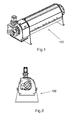
Fig. 1 is a perspective view of a device according to one embodiment of the screw press, -
Fig. 2 is a view of one end of the screw press ofFig. 1 . -
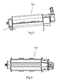
Fig. 3 is a side view of the screw press ofFig. 1 . -
Fig. 4 is a top view of the screw press ofFig. 1 . -
Fig. 5 shows a cross-sectional view of the screw press ofFig. 1 -
Fig. 6 shows a detailed view of a section of the screw press ofFig. 1 having mounted an inlet. -
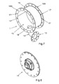
Fig. 7 shows detailed view of the inlet of the screw press ofFig. 1 . -
Fig. 8 shows an end piece to the inlet of the screw press ofFig. 1 . - With reference to
Figs. 1-8 , adevice 100 for removing liquid from a product to achieve a concentrate, is shown. The liquid to be removed from the product is water, why dewatering is an alternative term for the process performed by means of thedevice 100. The product to be treated by means of thedevice 100 is sludge produced in connection with waste water treatment as mentioned by way of introduction. When removing water from the sludge, the solids remain as a concentrate ready for further handling as desired. For example, such further handling could involve burning of the solids concentrate to generate energy. - The
device 100, also called screw press, includes aninlet 1, screw orauger 2,spraying nozzles 3, a drainage filter 4, afiltering filter 5, pressure orcolumn filter 6, aback pressure device 7,air pressure cylinder 8,outlet 9,drain 10 and agear motor 11. The drainage filter 4, thefiltering filter 5 and thecolumn filter 6 are mounted together to form a long screen that encircles theauger 2. Outside and around the screen arenozzles 3 mounted to enables cleaning of the screen or thefilter auger 2 is rotated by thegear motor 11. In a first end of the screen aninlet 1 are arranged adjacent enabling a feed of sludge into the interior of the screen. Adjacent to a second and opposite end of the screen a back pressure orpressure cone 7 are arranged and that through pneumatic orair pressure cylinders 8 makes it possible to maintain a constant back pressure atsludge outlet 9. The water that has been filtered through the screen are collected in the bottom area of the screw press and guided out of the screw press through thedrainage 10, whichdrainage 10 are located close to theinlet 1. Thescrew press 100 is normally arranged so that the first end of the screen is located lower than the second end of the screen to enable gravity drainage through thedrainage 10. - In
Fig. 6 , a detailed partial view of a section of thescrew press 100 is shown, where the screw or auger 2 (shown inFig. 5 ) is positioned in thearea 12. Thescrew press 100 is provided with aninlet 1, whichinlet 1 includes an inlet pipe ortube 19, through which the sludge is feed into thescrew press 100 and the screen. Theinlet pipe 19 has anend flange 13 provided in a free end of the inlet pipe for connecting to a piping system (not shown). Theinlet 1 is also provided with an end-piece 14, which can be used as a basis for a bearing for a shaft which drives the screw orauger 2. - In
Fig. 8 theinlet 1 is shown, which comprises acylindrical pipe section 15 provided withend flanges end flanges holes 17 for mounting theinlet 1 on thescrew press 100. Thecylindrical pipe section 15 is further provided with aninlet pipe 19, which is connected to thecylindrical pipe section 15 via anopening hole 18. - The
inlet pipe 19 is preferably bent 90 degrees from a first end at theopening hole 18 to the free end provided with theflange 13. - The
holes 17 of theend flanges inlet 1 are located in the center of the same radius of thecylindrical pipe section 15 and having equal spacing between theholes 17 along theend flanges inlet 1 relative to the screw press part in steps corresponding to the distance between twoholes 17. - In addition, the advantage is obtained that the
entire inlet 1 can be turned 180 degrees wherein theinlet pipe 19 also turns 180 degrees. Thereby the location of theinlet pipe 19 is flexible in relation to the rest of thescrew press 100. Thereby it is very easy to adjust theinlet pipe 19 to the connecting piping system, which makes the installation of the screw press in a given location much easier. - The operation of the
screw press 100 will now be described with reference to the drawings. When thescrew press 100 is operated, theauger 2 is rotated inside the screen formed by the drainage filter 4, thefiltering filter 5 and thecolumn filter 6. The sludge is fed, from a supply not illustrated, to thescrew press 100 via a piping system through theinlet pipe 19 and further into the interior of the screen via theinlet 1. After entering the interior of the drainage filter 4, which is the first section of the screen, the sludge will be fed towards theoutlet 9 of the drum by theauger 2. When fed through the interior of the screen, the sludge is dewatered gradually, which means that the water leaves the interior of the screen through thedifferent filters filtering filter 5 by density and in the third part of the passage through the screen the sludge is dewatering through slots of thefilter 6 by means of theback pressure device 7 provided by theair pressure cylinder 8. Finally the remaining sludge, also called the cake, is fed through theoutlet 9. The filtered water are collected in a bottom area of the screw press and guided out of the screw press through thedrainage 10 - Three dewatering zones for the sludge are created during the fed through the interior of the screen; a drainage zone, a filtering zone and pressure zone. The slots of the three
filters spray nozzles 3 arranged along and around thefilters filter - With the
screw press 100 according to the above embodiment it is possible dewater the sludge so that the solids content from being approximately 1 % of the sludge before dewatering to be approximately 18-25% of the sludge after dewatering. - As seen in
Figs. 1 ,3 ,4 and5 is thescrew press 100 provided with inspection hatches or lid enables easy access to the filters, the inlet and the outlet for service, maintenance and inspection of the different parts. - The invention is not limited to the embodiments described above and shown on the drawings, but can be supplemented and modified in any manner within the scope of the invention as defined by the enclosed claims.
Claims (8)
- A screw press (100) for dewatering sludge having inlet (1) for feeding the sludge into the screw press, an outlet (9), and one or more filters for dewatering the sludge having an auger (2) arranged inside the filters for feed the sludge through the filters, characterized in that the inlet (1) comprises a cylindrical piece of pipe (15) with end flanges (16A, 16B), which is provided with a plurality of holes (17), and an inlet pipe (19) which is connected to the cylindrical pipe section (15) via an opening hole (18).
- A screw press (1) for dewatering sludge according to claim 1, wherein the inlet pipe (19) is bent 90 degrees from a first end connected to the inlet (1) to a second free end.
- A screw press (1) for dewatering sludge according to claim 1 or 2, wherein the inlet pipe (19) is provided with a flange (13) in the free end for connecting to a piping system.
- A screw press (1) for dewatering sludge according to one or more of claims 1 to 3, wherein the holes (17) of the end flanges (16A, 16B) are arranged at the center of the same radius of the cylindrical pipe section (15) and with equidistant spacing of the holes (17) relative to the center.
- A screw press (1) for dewatering sludge according to one or more of claims 1 to 4, wherein the inlet (1) is provided with an end piece (14).
- A screw press (100) for dewatering sludge having three after each other arranged filters for dewatering, including, a drainage filter (4), a filtering filter (5), and a column filter (6), and which also includes a back pressure device (7) for creating a pressure inside the filters, characterized in that the screw press (100) further includes an inlet (1) comprising a cylindrical piece of pipe (15) with end flanges (16A, 16B), which is provided with a plurality of holes (17), and an inlet pipe (19) which is connected to the cylindrical pipe section (15) via an opening hole (18), where the inlet (1) is flexibly arranged relatively to the rest of the screw press to be adjusted to a piping system connected to the screw press (100).
- A screw press (1) for dewatering sludge according to claim 1, wherein the holes (17) arranged on the end flanges (16A, 16B) enables the inlet (1) to be rotated relatively to the rest of the screw press (100).
- The use of the screw press (100) according to one or more of claims 1 to 7 for dewatering sludge including liquid state material.
Priority Applications (1)
| Application Number | Priority Date | Filing Date | Title |
|---|---|---|---|
| PL13160523T PL2641879T3 (en) | 2012-03-22 | 2013-03-22 | A screw press and the use of the screw press for dewatering of sludge |
Applications Claiming Priority (1)
| Application Number | Priority Date | Filing Date | Title |
|---|---|---|---|
| DKBA201200051U DK201200051U3 (en) | 2012-03-22 | 2012-03-22 | Screw press and application |
Publications (3)
| Publication Number | Publication Date |
|---|---|
| EP2641879A2 true EP2641879A2 (en) | 2013-09-25 |
| EP2641879A3 EP2641879A3 (en) | 2014-01-22 |
| EP2641879B1 EP2641879B1 (en) | 2018-02-28 |
Family
ID=47997101
Family Applications (1)
| Application Number | Title | Priority Date | Filing Date |
|---|---|---|---|
| EP13160523.0A Not-in-force EP2641879B1 (en) | 2012-03-22 | 2013-03-22 | A screw press and the use of the screw press for dewatering of sludge |
Country Status (3)
| Country | Link |
|---|---|
| EP (1) | EP2641879B1 (en) |
| DK (2) | DK201200051U3 (en) |
| PL (1) | PL2641879T3 (en) |
Cited By (1)
| Publication number | Priority date | Publication date | Assignee | Title |
|---|---|---|---|---|
| RU192467U1 (en) * | 2018-05-15 | 2019-09-17 | Юрий Петрович Борисов | Screw filter - press |
Families Citing this family (1)
| Publication number | Priority date | Publication date | Assignee | Title |
|---|---|---|---|---|
| CN112477267A (en) * | 2020-11-18 | 2021-03-12 | 江苏一环集团有限公司 | Shaftless screw press |
Family Cites Families (5)
| Publication number | Priority date | Publication date | Assignee | Title |
|---|---|---|---|---|
| US1604652A (en) * | 1925-06-17 | 1926-10-26 | Fred W Manning | Process of and apparatus for treating, dewatering, compressing, and drying industrial wastes, sewage solids, etc. |
| US4582568A (en) * | 1983-09-15 | 1986-04-15 | Beloit Corporation | Apparatus for controlling the consistency of a pulp suspension |
| US4781823A (en) * | 1987-04-13 | 1988-11-01 | Fukoku Kogyo Company Limited | Pre-filtering apparatus for use in continuous press |
| ES2196519T3 (en) * | 1998-12-21 | 2003-12-16 | Walter Schmid Ag | DEHYDRATION OF FERMENTATION PRODUCTS BY SPINDLE PRESS. |
| JP2003220308A (en) * | 2002-01-31 | 2003-08-05 | Tsurumi Mfg Co Ltd | Screw filtration dewatering equipment |
-
2012
- 2012-03-22 DK DKBA201200051U patent/DK201200051U3/en not_active IP Right Cessation
-
2013
- 2013-03-22 EP EP13160523.0A patent/EP2641879B1/en not_active Not-in-force
- 2013-03-22 PL PL13160523T patent/PL2641879T3/en unknown
- 2013-03-22 DK DK13160523.0T patent/DK2641879T3/en active
Non-Patent Citations (1)
| Title |
|---|
| None |
Cited By (1)
| Publication number | Priority date | Publication date | Assignee | Title |
|---|---|---|---|---|
| RU192467U1 (en) * | 2018-05-15 | 2019-09-17 | Юрий Петрович Борисов | Screw filter - press |
Also Published As
| Publication number | Publication date |
|---|---|
| PL2641879T3 (en) | 2018-06-29 |
| EP2641879B1 (en) | 2018-02-28 |
| DK201200051U3 (en) | 2013-07-12 |
| DK2641879T3 (en) | 2018-06-06 |
| EP2641879A3 (en) | 2014-01-22 |
Similar Documents
| Publication | Publication Date | Title |
|---|---|---|
| EP3858789B1 (en) | A separation device and method to separate contaminants from contaminated water | |
| EA024103B1 (en) | Screw extruder | |
| CN106687187B (en) | Vertical Separator for Slurry Treatment | |
| JP2014530760A (en) | Dehydrator | |
| US8146750B2 (en) | Rotary fan press | |
| KR20120066280A (en) | Screw type dehydration appratus | |
| EP2641879B1 (en) | A screw press and the use of the screw press for dewatering of sludge | |
| EP2874726B1 (en) | Internally fed drum filter for treating waste water comprising an inlet distribution arrangement | |
| KR20200133770A (en) | Punching metal drum screen device | |
| EP2628519B1 (en) | Device for removing liquid | |
| JP2004314130A (en) | Screw-press dehydrator | |
| KR20120091553A (en) | A solid-and-liquid seperating apparatus for treating effluents, a screw dehydration apparatus and a treatment using them | |
| KR20160070643A (en) | filtering apparatus for wastewater | |
| JP2017176903A (en) | Sewage sludge treatment system | |
| EP1335785B1 (en) | Filtration apparatus | |
| KR101040201B1 (en) | Rotary Pressurized Wastewater Treatment System | |
| US20200283323A1 (en) | Inline dewatering system | |
| KR101437908B1 (en) | Vertical type screw dehydrator | |
| KR100962029B1 (en) | Hydraulic screener | |
| RU2503622C1 (en) | Effluents industrial effluents treatment plant | |
| JP2021186735A (en) | Filtering device | |
| JP2011020080A (en) | Apparatus for separating and dehydrating sewage sludge | |
| KR20080007995A (en) | Foreign Material Filter | |
| US20100326927A1 (en) | Rotary scraper plows for rotary fan press | |
| KR200409043Y1 (en) | Sludge Treatment System with Concentration and Dewatering Line |
Legal Events
| Date | Code | Title | Description |
|---|---|---|---|
| PUAI | Public reference made under article 153(3) epc to a published international application that has entered the european phase |
Free format text: ORIGINAL CODE: 0009012 |
|
| AK | Designated contracting states |
Kind code of ref document: A2 Designated state(s): AL AT BE BG CH CY CZ DE DK EE ES FI FR GB GR HR HU IE IS IT LI LT LU LV MC MK MT NL NO PL PT RO RS SE SI SK SM TR |
|
| AX | Request for extension of the european patent |
Extension state: BA ME |
|
| RIC1 | Information provided on ipc code assigned before grant |
Ipc: B30B 9/12 20060101ALI20131011BHEP Ipc: C02F 11/12 20060101AFI20131011BHEP Ipc: B01D 33/27 20060101ALI20131011BHEP Ipc: B01D 33/72 20060101ALI20131011BHEP |
|
| PUAL | Search report despatched |
Free format text: ORIGINAL CODE: 0009013 |
|
| AK | Designated contracting states |
Kind code of ref document: A3 Designated state(s): AL AT BE BG CH CY CZ DE DK EE ES FI FR GB GR HR HU IE IS IT LI LT LU LV MC MK MT NL NO PL PT RO RS SE SI SK SM TR |
|
| AX | Request for extension of the european patent |
Extension state: BA ME |
|
| RIC1 | Information provided on ipc code assigned before grant |
Ipc: B01D 29/64 20060101ALI20131218BHEP Ipc: B30B 9/12 20060101ALI20131218BHEP Ipc: C02F 11/12 20060101AFI20131218BHEP Ipc: B01D 29/82 20060101ALI20131218BHEP Ipc: B01D 29/35 20060101ALI20131218BHEP |
|
| 17P | Request for examination filed |
Effective date: 20140321 |
|
| RBV | Designated contracting states (corrected) |
Designated state(s): AL AT BE BG CH CY CZ DE DK EE ES FI FR GB GR HR HU IE IS IT LI LT LU LV MC MK MT NL NO PL PT RO RS SE SI SK SM TR |
|
| GRAP | Despatch of communication of intention to grant a patent |
Free format text: ORIGINAL CODE: EPIDOSNIGR1 |
|
| STAA | Information on the status of an ep patent application or granted ep patent |
Free format text: STATUS: GRANT OF PATENT IS INTENDED |
|
| INTG | Intention to grant announced |
Effective date: 20171117 |
|
| GRAS | Grant fee paid |
Free format text: ORIGINAL CODE: EPIDOSNIGR3 |
|
| GRAA | (expected) grant |
Free format text: ORIGINAL CODE: 0009210 |
|
| STAA | Information on the status of an ep patent application or granted ep patent |
Free format text: STATUS: THE PATENT HAS BEEN GRANTED |
|
| AK | Designated contracting states |
Kind code of ref document: B1 Designated state(s): AL AT BE BG CH CY CZ DE DK EE ES FI FR GB GR HR HU IE IS IT LI LT LU LV MC MK MT NL NO PL PT RO RS SE SI SK SM TR |
|
| REG | Reference to a national code |
Ref country code: GB Ref legal event code: FG4D Ref country code: CH Ref legal event code: EP |
|
| REG | Reference to a national code |
Ref country code: AT Ref legal event code: REF Ref document number: 973896 Country of ref document: AT Kind code of ref document: T Effective date: 20180315 Ref country code: FR Ref legal event code: PLFP Year of fee payment: 6 |
|
| REG | Reference to a national code |
Ref country code: IE Ref legal event code: FG4D |
|
| REG | Reference to a national code |
Ref country code: DE Ref legal event code: R096 Ref document number: 602013033610 Country of ref document: DE |
|
| REG | Reference to a national code |
Ref country code: SE Ref legal event code: TRGR |
|
| REG | Reference to a national code |
Ref country code: DK Ref legal event code: T3 Effective date: 20180528 |
|
| REG | Reference to a national code |
Ref country code: NL Ref legal event code: MP Effective date: 20180228 |
|
| REG | Reference to a national code |
Ref country code: LT Ref legal event code: MG4D |
|
| REG | Reference to a national code |
Ref country code: AT Ref legal event code: MK05 Ref document number: 973896 Country of ref document: AT Kind code of ref document: T Effective date: 20180228 |
|
| PG25 | Lapsed in a contracting state [announced via postgrant information from national office to epo] |
Ref country code: HR Free format text: LAPSE BECAUSE OF FAILURE TO SUBMIT A TRANSLATION OF THE DESCRIPTION OR TO PAY THE FEE WITHIN THE PRESCRIBED TIME-LIMIT Effective date: 20180228 Ref country code: LT Free format text: LAPSE BECAUSE OF FAILURE TO SUBMIT A TRANSLATION OF THE DESCRIPTION OR TO PAY THE FEE WITHIN THE PRESCRIBED TIME-LIMIT Effective date: 20180228 Ref country code: NL Free format text: LAPSE BECAUSE OF FAILURE TO SUBMIT A TRANSLATION OF THE DESCRIPTION OR TO PAY THE FEE WITHIN THE PRESCRIBED TIME-LIMIT Effective date: 20180228 Ref country code: CY Free format text: LAPSE BECAUSE OF FAILURE TO SUBMIT A TRANSLATION OF THE DESCRIPTION OR TO PAY THE FEE WITHIN THE PRESCRIBED TIME-LIMIT Effective date: 20180228 Ref country code: ES Free format text: LAPSE BECAUSE OF FAILURE TO SUBMIT A TRANSLATION OF THE DESCRIPTION OR TO PAY THE FEE WITHIN THE PRESCRIBED TIME-LIMIT Effective date: 20180228 Ref country code: FI Free format text: LAPSE BECAUSE OF FAILURE TO SUBMIT A TRANSLATION OF THE DESCRIPTION OR TO PAY THE FEE WITHIN THE PRESCRIBED TIME-LIMIT Effective date: 20180228 Ref country code: NO Free format text: LAPSE BECAUSE OF FAILURE TO SUBMIT A TRANSLATION OF THE DESCRIPTION OR TO PAY THE FEE WITHIN THE PRESCRIBED TIME-LIMIT Effective date: 20180528 |
|
| PG25 | Lapsed in a contracting state [announced via postgrant information from national office to epo] |
Ref country code: AT Free format text: LAPSE BECAUSE OF FAILURE TO SUBMIT A TRANSLATION OF THE DESCRIPTION OR TO PAY THE FEE WITHIN THE PRESCRIBED TIME-LIMIT Effective date: 20180228 Ref country code: RS Free format text: LAPSE BECAUSE OF FAILURE TO SUBMIT A TRANSLATION OF THE DESCRIPTION OR TO PAY THE FEE WITHIN THE PRESCRIBED TIME-LIMIT Effective date: 20180228 Ref country code: BG Free format text: LAPSE BECAUSE OF FAILURE TO SUBMIT A TRANSLATION OF THE DESCRIPTION OR TO PAY THE FEE WITHIN THE PRESCRIBED TIME-LIMIT Effective date: 20180528 Ref country code: GR Free format text: LAPSE BECAUSE OF FAILURE TO SUBMIT A TRANSLATION OF THE DESCRIPTION OR TO PAY THE FEE WITHIN THE PRESCRIBED TIME-LIMIT Effective date: 20180529 Ref country code: LV Free format text: LAPSE BECAUSE OF FAILURE TO SUBMIT A TRANSLATION OF THE DESCRIPTION OR TO PAY THE FEE WITHIN THE PRESCRIBED TIME-LIMIT Effective date: 20180228 |
|
| PG25 | Lapsed in a contracting state [announced via postgrant information from national office to epo] |
Ref country code: AL Free format text: LAPSE BECAUSE OF FAILURE TO SUBMIT A TRANSLATION OF THE DESCRIPTION OR TO PAY THE FEE WITHIN THE PRESCRIBED TIME-LIMIT Effective date: 20180228 Ref country code: RO Free format text: LAPSE BECAUSE OF FAILURE TO SUBMIT A TRANSLATION OF THE DESCRIPTION OR TO PAY THE FEE WITHIN THE PRESCRIBED TIME-LIMIT Effective date: 20180228 Ref country code: EE Free format text: LAPSE BECAUSE OF FAILURE TO SUBMIT A TRANSLATION OF THE DESCRIPTION OR TO PAY THE FEE WITHIN THE PRESCRIBED TIME-LIMIT Effective date: 20180228 Ref country code: IT Free format text: LAPSE BECAUSE OF FAILURE TO SUBMIT A TRANSLATION OF THE DESCRIPTION OR TO PAY THE FEE WITHIN THE PRESCRIBED TIME-LIMIT Effective date: 20180228 |
|
| REG | Reference to a national code |
Ref country code: CH Ref legal event code: PL |
|
| REG | Reference to a national code |
Ref country code: DE Ref legal event code: R097 Ref document number: 602013033610 Country of ref document: DE |
|
| PG25 | Lapsed in a contracting state [announced via postgrant information from national office to epo] |
Ref country code: SK Free format text: LAPSE BECAUSE OF FAILURE TO SUBMIT A TRANSLATION OF THE DESCRIPTION OR TO PAY THE FEE WITHIN THE PRESCRIBED TIME-LIMIT Effective date: 20180228 Ref country code: SM Free format text: LAPSE BECAUSE OF FAILURE TO SUBMIT A TRANSLATION OF THE DESCRIPTION OR TO PAY THE FEE WITHIN THE PRESCRIBED TIME-LIMIT Effective date: 20180228 Ref country code: MC Free format text: LAPSE BECAUSE OF FAILURE TO SUBMIT A TRANSLATION OF THE DESCRIPTION OR TO PAY THE FEE WITHIN THE PRESCRIBED TIME-LIMIT Effective date: 20180228 Ref country code: CZ Free format text: LAPSE BECAUSE OF FAILURE TO SUBMIT A TRANSLATION OF THE DESCRIPTION OR TO PAY THE FEE WITHIN THE PRESCRIBED TIME-LIMIT Effective date: 20180228 |
|
| REG | Reference to a national code |
Ref country code: BE Ref legal event code: MM Effective date: 20180331 |
|
| REG | Reference to a national code |
Ref country code: IE Ref legal event code: MM4A |
|
| PG25 | Lapsed in a contracting state [announced via postgrant information from national office to epo] |
Ref country code: LU Free format text: LAPSE BECAUSE OF NON-PAYMENT OF DUE FEES Effective date: 20180322 |
|
| PLBE | No opposition filed within time limit |
Free format text: ORIGINAL CODE: 0009261 |
|
| STAA | Information on the status of an ep patent application or granted ep patent |
Free format text: STATUS: NO OPPOSITION FILED WITHIN TIME LIMIT |
|
| GBPC | Gb: european patent ceased through non-payment of renewal fee |
Effective date: 20180528 |
|
| PG25 | Lapsed in a contracting state [announced via postgrant information from national office to epo] |
Ref country code: IE Free format text: LAPSE BECAUSE OF NON-PAYMENT OF DUE FEES Effective date: 20180322 |
|
| PGFP | Annual fee paid to national office [announced via postgrant information from national office to epo] |
Ref country code: PL Payment date: 20181219 Year of fee payment: 7 |
|
| 26N | No opposition filed |
Effective date: 20181129 |
|
| PG25 | Lapsed in a contracting state [announced via postgrant information from national office to epo] |
Ref country code: CH Free format text: LAPSE BECAUSE OF NON-PAYMENT OF DUE FEES Effective date: 20180331 Ref country code: SI Free format text: LAPSE BECAUSE OF FAILURE TO SUBMIT A TRANSLATION OF THE DESCRIPTION OR TO PAY THE FEE WITHIN THE PRESCRIBED TIME-LIMIT Effective date: 20180228 Ref country code: LI Free format text: LAPSE BECAUSE OF NON-PAYMENT OF DUE FEES Effective date: 20180331 Ref country code: BE Free format text: LAPSE BECAUSE OF NON-PAYMENT OF DUE FEES Effective date: 20180331 |
|
| PG25 | Lapsed in a contracting state [announced via postgrant information from national office to epo] |
Ref country code: GB Free format text: LAPSE BECAUSE OF NON-PAYMENT OF DUE FEES Effective date: 20180528 |
|
| PGFP | Annual fee paid to national office [announced via postgrant information from national office to epo] |
Ref country code: DE Payment date: 20190312 Year of fee payment: 7 |
|
| PGFP | Annual fee paid to national office [announced via postgrant information from national office to epo] |
Ref country code: DK Payment date: 20190312 Year of fee payment: 7 Ref country code: FR Payment date: 20190213 Year of fee payment: 7 Ref country code: SE Payment date: 20190311 Year of fee payment: 7 |
|
| PG25 | Lapsed in a contracting state [announced via postgrant information from national office to epo] |
Ref country code: MT Free format text: LAPSE BECAUSE OF NON-PAYMENT OF DUE FEES Effective date: 20180322 |
|
| PG25 | Lapsed in a contracting state [announced via postgrant information from national office to epo] |
Ref country code: TR Free format text: LAPSE BECAUSE OF FAILURE TO SUBMIT A TRANSLATION OF THE DESCRIPTION OR TO PAY THE FEE WITHIN THE PRESCRIBED TIME-LIMIT Effective date: 20180228 |
|
| PG25 | Lapsed in a contracting state [announced via postgrant information from national office to epo] |
Ref country code: HU Free format text: LAPSE BECAUSE OF FAILURE TO SUBMIT A TRANSLATION OF THE DESCRIPTION OR TO PAY THE FEE WITHIN THE PRESCRIBED TIME-LIMIT; INVALID AB INITIO Effective date: 20130322 Ref country code: PT Free format text: LAPSE BECAUSE OF FAILURE TO SUBMIT A TRANSLATION OF THE DESCRIPTION OR TO PAY THE FEE WITHIN THE PRESCRIBED TIME-LIMIT Effective date: 20180228 |
|
| PG25 | Lapsed in a contracting state [announced via postgrant information from national office to epo] |
Ref country code: MK Free format text: LAPSE BECAUSE OF NON-PAYMENT OF DUE FEES Effective date: 20180228 |
|
| PG25 | Lapsed in a contracting state [announced via postgrant information from national office to epo] |
Ref country code: IS Free format text: LAPSE BECAUSE OF FAILURE TO SUBMIT A TRANSLATION OF THE DESCRIPTION OR TO PAY THE FEE WITHIN THE PRESCRIBED TIME-LIMIT Effective date: 20180628 |
|
| REG | Reference to a national code |
Ref country code: DE Ref legal event code: R119 Ref document number: 602013033610 Country of ref document: DE |
|
| REG | Reference to a national code |
Ref country code: DK Ref legal event code: EBP Effective date: 20200331 |
|
| PG25 | Lapsed in a contracting state [announced via postgrant information from national office to epo] |
Ref country code: FR Free format text: LAPSE BECAUSE OF NON-PAYMENT OF DUE FEES Effective date: 20200331 Ref country code: DE Free format text: LAPSE BECAUSE OF NON-PAYMENT OF DUE FEES Effective date: 20201001 Ref country code: SE Free format text: LAPSE BECAUSE OF NON-PAYMENT OF DUE FEES Effective date: 20200323 |
|
| PG25 | Lapsed in a contracting state [announced via postgrant information from national office to epo] |
Ref country code: DK Free format text: LAPSE BECAUSE OF NON-PAYMENT OF DUE FEES Effective date: 20200331 |
|
| PG25 | Lapsed in a contracting state [announced via postgrant information from national office to epo] |
Ref country code: PL Free format text: LAPSE BECAUSE OF NON-PAYMENT OF DUE FEES Effective date: 20200322 |