EP2641831B1 - Helicopter skid type landing gear - Google Patents
Helicopter skid type landing gear Download PDFInfo
- Publication number
- EP2641831B1 EP2641831B1 EP12400007.6A EP12400007A EP2641831B1 EP 2641831 B1 EP2641831 B1 EP 2641831B1 EP 12400007 A EP12400007 A EP 12400007A EP 2641831 B1 EP2641831 B1 EP 2641831B1
- Authority
- EP
- European Patent Office
- Prior art keywords
- torsion bar
- cross beam
- fuselage
- bar spring
- skid
- Prior art date
- Legal status (The legal status is an assumption and is not a legal conclusion. Google has not performed a legal analysis and makes no representation as to the accuracy of the status listed.)
- Not-in-force
Links
- 238000006073 displacement reaction Methods 0.000 claims 2
- 238000013016 damping Methods 0.000 description 17
- 238000010521 absorption reaction Methods 0.000 description 10
- 230000035939 shock Effects 0.000 description 4
- 238000013459 approach Methods 0.000 description 3
- 238000010168 coupling process Methods 0.000 description 2
- 238000005859 coupling reaction Methods 0.000 description 2
- 230000005489 elastic deformation Effects 0.000 description 2
- 239000000463 material Substances 0.000 description 2
- 229910000831 Steel Inorganic materials 0.000 description 1
- 230000000712 assembly Effects 0.000 description 1
- 238000000429 assembly Methods 0.000 description 1
- 238000005452 bending Methods 0.000 description 1
- 238000010586 diagram Methods 0.000 description 1
- 230000002708 enhancing effect Effects 0.000 description 1
- 231100001261 hazardous Toxicity 0.000 description 1
- 230000001788 irregular Effects 0.000 description 1
- 238000012423 maintenance Methods 0.000 description 1
- 239000002184 metal Substances 0.000 description 1
- 230000021715 photosynthesis, light harvesting Effects 0.000 description 1
- 230000000704 physical effect Effects 0.000 description 1
- 230000002441 reversible effect Effects 0.000 description 1
- 239000007787 solid Substances 0.000 description 1
- 239000010959 steel Substances 0.000 description 1
Images


Classifications
-
- B—PERFORMING OPERATIONS; TRANSPORTING
- B64—AIRCRAFT; AVIATION; COSMONAUTICS
- B64C—AEROPLANES; HELICOPTERS
- B64C25/00—Alighting gear
- B64C25/32—Alighting gear characterised by elements which contact the ground or similar surface
- B64C25/52—Skis or runners
-
- B—PERFORMING OPERATIONS; TRANSPORTING
- B64—AIRCRAFT; AVIATION; COSMONAUTICS
- B64C—AEROPLANES; HELICOPTERS
- B64C25/00—Alighting gear
- B64C25/32—Alighting gear characterised by elements which contact the ground or similar surface
- B64C25/58—Arrangements or adaptations of shock-absorbers or springs
- B64C25/62—Spring shock-absorbers; Springs
-
- B—PERFORMING OPERATIONS; TRANSPORTING
- B64—AIRCRAFT; AVIATION; COSMONAUTICS
- B64C—AEROPLANES; HELICOPTERS
- B64C25/00—Alighting gear
- B64C25/32—Alighting gear characterised by elements which contact the ground or similar surface
- B64C2025/325—Alighting gear characterised by elements which contact the ground or similar surface specially adapted for helicopters
Definitions
- the invention is related to a helicopter with a skid type landing gear and to a skid type landing gear.
- Landing gears of helicopters have to be designed to allow absorption of the vertical energy of a landing, by elastic deformation during regular landings and by plastic deformation during hard landings.
- the respective plastic deformations can reach a value up to 360 mm in vertical direction at the aft cross tube and up to 460 mm at the forward cross tube.
- a landing gear of a helicopter can contribute to the so called ground resonance phenomenon. Especially the stiffness and the damping properties of the landing gear influence the ground resonance.
- Ground resonance is a hazardous condition that can occur any time the rotor of a helicopter or gyroplane is turning while the aircraft is on the ground.
- the vertical stiffness refers exclusively to the linear or elastic portion of the load vs. stroke curves, because it is in the linear or elastic portion of said curves, in which skid gears function during normal helicopter operation.
- the vertical stiffness is important to attenuate landing energy.
- the longitudinal stiffness is important because it is a primary source of frequency response to ground resonance frequency.
- the most economical way to solve the ground resonance problem is to change the stiffness and damping behaviour of the skid type landing gear so that no ground resonance occurs. This can be done by adding some diagonal struts in between the components of skid type landing gears at the cost of weight and drag.
- a specific cross section form and material of cross tube members can influence the stiffness. This is the practicable way but not the most elegant. Sometimes a damping element is added to a cross tube, if the deflection of the tube allows effective damping at a certain point.
- the document US 4196878 A (Aerospatiale) discloses a landing gear for rotary-wing aircraft having two main skids connected to the aircraft structure by two cantilevered arcuate supports. Each skid has at least one flexible element capable of flexing resiliently upon contacting the ground.
- the document US 4270711 A discloses a helicopter landing gear assembly which includes a pair of cross tubes having a pair of struts connected at the outboard ends thereof.
- the document US 6427942 A discloses a skid landing gear for a helicopter, in which the directional stiffness of the cross members of the skid landing gear have been de-coupled from one another, such that the longitudinal stiffness of the cross members may be independent of the vertical stiffness and fatigue life of the cross members.
- the skid landing gear has non-symmetric-section cross members and/or distribution of different materials within the cross section for de-coupling the vertical stiffness of the cross members from the longitudinal stiffness.
- mounting devices are employed that provide compliance in selected directions, thereby de-coupling the directional stiffness.
- US 4519559 A discloses a landing gear of the undercarriage of a helicopter with skids connected to upwardly extending cross tubes pivotally connected to an airframe structure. Dampers have a first end pivotally connected to said cross tubes and a second end pivotally connected to the airframe structure. Hydraulic cylinders in the respective dampers are interconnected through hydraulic restoring devices. Hydraulic restoring devices yieldable urge the pistons in each of the hydraulic cylinders to an equilibrium position, thereby restoring the length of each landing gear to an equilibrium length following a disturbance.
- the respective dampers are not suitable to absorb any vertical energy at landing of the helicopter. Stiffness to absorb the vertical energy of the landing is provided by the cross tubes and skids of the landing gear of US 4519559 A .
- the teaching of US 4519559 A does not address ground resonance problems of helicopters.
- each side shock absorbing portion is divided into two independent longitudinal sections, frontwards and backwards. Each section have a strut member.
- the two independent longitudinal sections have a common landing surface engaging means of the skid type, defined by an elongated tubular member or skid. Each skid is linked to the chassis by two front / back strut members.
- the two independent longitudinal sections also have operatively distinct rod sections which extend in opposite directions from an intermediate reference location at which the rod structure is operatively and non-rotatably secured to the aircraft chassis.
- a helicopter with a fuselage comprises a skid-type landing gear mounted to said fuselage.
- Said skid-type landing gear comprises cross beams with skids being each disposed in an essentially longitudinal direction laterally on a respective side of a longitudinal midplane in elevation of the landing gear.
- Each of said skids is mounted on one respective side of the longitudinal midplane to a lateral end of at least one of said cross beams.
- the cross beams are designed as a supporting structure to transfer forces and moments between skids and fuselage.
- Each of the cross beams is provided with an inner end next to the fuselage. Fixed bearings and floating bearings of the inventive helicopter skid-type landing gear are provided at the fuselage.
- Torsion bar springs are provided between said fixed bearings and floating bearings with each of said torsion bar springs being fixed by means of at least one of said fixed bearings whereas said torsion bar springs are allowed to rotate around their longitudinal axis relative to said floating bearings.
- Said respective inner end of each cross beam is attached to said torsion bar spring at the floating bearing by means of splines in such a manner that forces and moments are transferred from the respective inner end of each cross beam to said torsion bar spring, i. e. the cross beam becomes a pivotable cantilever cross beam as the cross beam may rotate (pivot) with the torsion bar spring it is mounted to relative to the floating bearing while transferring all its forces and bending moments into the torsion bar spring.
- the inventive helicopter skid-type landing gear provides remedy to ground resonance problems by discrete means for elastic deformations of the landing gear and for the damping while fulfilling among others the regulations FAR/CS-27, FAR/CS-29 concerning energy absorption.
- the dampers and the torsion bar springs of the inventive helicopter skid-type landing gear are two distinct elements, not automatically aligned.
- the inventive helicopter skid-type landing gear is provided with four pivotable cantilever cross beams each supported at the fuselage on respective torsion bar springs.
- the torsion bar springs are attached at one end to the fuselage structure with a fixed bearing principle for transfer of torsion moments from the torsion bar springs into the fuselage structure via the fixed bearings.
- At their opposed end each of the torsion bar springs are attached to the pivotable cantilever cross beam via a floating bearing principle for transfer of forces into the floating bearing and transfer of torsion moments into the torsion bar springs.
- the torsion bar springs provide for elastic stiffness of the inventive helicopter skid-type landing gear to absorb vertical energy at landing of the helicopter together with contributions to said elastic stiffness from the cross tubes and the skids.
- the discrete dampers connected with one end to the pivotable cantilever cross beams and with their opposed end to the fuselage structure allow controlled damping of the inventive helicopter skid-type landing gear and the discrete dampers provide velocity dependant energy dissipation to absorb vertical kinetic energy at landing of the helicopter.
- the forces acting at landing of the inventive helicopter are split in two force components: one component is fully reversible and acts as torsion moment at the torsion bar springs and the second component are forces to the damping.
- the invention allows controlled energy absorption during landing and controllable and tunable stiffness- and damping behaviour of the inventive helicopter skid-type landing gear to avoid ground resonance.
- Another advantage of the invention is to allow elastic energy absorption instead of plastic energy absorption, thus avoiding or reducing a regular exchange of conventional cross tubes after hard landings being especially an advantage for skid type helicopters operating on ship decks as usually the cross tubes of skid type landing gears of helicopters operating on ships need to be replaced quite often as they reach soon their limits in setting.
- the total weight of the inventive skid-type landing gears is in the same order of magnitude as the weight of current skid-type landing gears.
- the discrete dampers and torsion bar springs of the inventive skid-type landing gears can be easily replaced in case of damage.
- the pivotable cantilever cross beams are connected to one end of the torsional bar spring mounted in a floating bearing.
- said pivotable cantilever cross beams on either side of the fuselage are symmetric with respect to the midplane.
- the discrete dampers are provided with separate means for attachment to the pivotable cantilever cross beams and to the fuselage.
- up to four (4) pivoted cantilever cross beams are attached to two torsion bar springs in combination with four (4) dampers to absorb required energies elastically/reversibly.
- the at least one discrete damper is of the tunable and/or self-regulating liquid-type.
- the combination of elastic torsion bar springs with discrete dampers of the inventive skid-type landing gears allow precise fine tuning of said energy absorption with said discrete means whereas with the designs of skid type landing gears of the state of the art it is a matter of experience/analysis and trial and error to find the correct stiffness and damping to avoid ground resonance under all possible landing attitudes.
- two pivotable cantilever cross beams are attached to two torsion bar springs in combination with two dampers on either side of the fuselage preferably symmetric with respect to the midplane of the helicopter.
- a left side of a helicopter's skid type landing gear 10 comprises two aligned torsion bar springs 1.
- Each torsion bar spring 1 has two ends. A first end is mounted into a fuselage fitting 6 with an integrated floating bearing 7 for each torsion bar spring 1.
- a second end of each torsion bar spring 1 is mounted to a fuselage 8 of the helicopter (not shown) by means of a fixed bearing 9.
- One torsion bar spring 1 going all the way through the fixed bearing 9 to the floating bearings 7 may replace the two aligned torsion bar springs 1.
- the floating bearings 7 are opposed to each other with respective distances relative to the fixed bearing 9 in between.
- the torsion bar springs 1 have an essentially cylindrical cross section.
- the torsion bar springs 1 are made of metal, such as steel.
- Two bow shaped pivoting cantilever cross beams 3, 4 are mounted with their respective inner ends to the torsion bar springs 1 by special means, e.g. splines (not shown) at the respective floating bearings 7.
- the two pivoting cantilever cross beams 3, 4 are attached essentially rectangular at their respective outer lateral ends to a common skid 5 with the pivoting cantilever cross beam 3 being attached next to a forward end of skid 5.
- the cross beams 3, 4 are each disposed in an essentially transversal direction relative to a main longitudinal axis of the helicopter (not shown).
- the skids 5 are mounted laterally, each on a respective side of a longitudinal midplane in elevation of the landing gear 10.
- a tunable and/or self-regulating liquid-type damper 2 is mounted with its cylinder side to the forward pivoting cantilever cross beam 3 and with its piston side to the fuselage fitting 6 to absorb energies transferred from the forward pivoting cantilever cross beam 3 and to allow fine tuning with regard to damping to avoid ground resonance.
- the cantilever cross beam 3 is provided with means, e.g. brackets 11 to attach said discrete damper 2.
- the orientation of the damper 2 is slightly inclined with regard to a principal direction of the pivoting cantilever cross beam 3.
- a further tunable and/or self-regulating liquid-type damper 2 is correspondingly mounted with its cylinder side to the rearward pivoting cantilever cross beam 4 and with its piston side to the fuselage fitting 6.
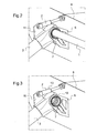
- Fig. 2 corresponding features are referred to with the references of Fig. 1 .
- the torsion bar spring 1 is mounted into a circular opening with gearing of the floating bearing 7.
- the forward pivoting cantilever cross beam 3 is mounted to the floating bearing 7.
- the floating bearing 7 is mounted in the fitting 6 attached to the fuselage 8.
- the floating bearing 7 is shown in more detail in Fig. 3 .
- the forward pivoting cantilever cross beam 3 is able to rotate with the gearing 12 of the floating bearing 7 relative to the fitting 6.
- the damper 2 is driven with its cylinder side 13 by the forward pivoting cantilever cross beam 3 relative to the fuselage fitting 6.
- the floating bearing 7 is mounted inside the fitting 6 with an essentially u-shaped rectangular casing 14.
- the torsion bar spring 1 is coaxially supported by journal-, taper- or roller bearings 15, 16 mounted into coaxial circular openings of the fitting 6 and the torsion bar spring 1, such that the torsion bar spring 1 is rotatable coaxially with the bearings 15, 16.
- the pivoting cantilever cross beam 3 is provided on an inner circumference of its opening with the gearing 12 and the torsion bar spring 1 is on an outer circumference provided with a coaxial gearing that fits with the gearing 12 on the inner circumference of the pivoting cantilever cross beam 3.
- the torsion bar spring 1 carries the pivoting cantilever cross beam 3 relative to the fitting 6.
- Fig. 5 there are two curves: a lower one for the energy absorption at the forward cantilever cross beam 3 and an upper one for the energy absorption at the rearward cantilever cross beam 4.
- the energy absorption at the forward cantilever cross beam 3 is about 10 000 J for a load of 30-40 kN and a stroke of 300-400 mm at the landing gear 10.
- the energy absorption at the rearward cantilever cross beam 4 is about 14 000 J for a load of 50-60 kN and a stroke of 300-400 mm at the landing gear 10.
- the Young's modulus of the torsion bar spring 1 is from 200 000 N/mm 2 -220 000 N/mm 2 at a Poisson's ratio of about 0.3 and a shear modulus of 80 000 N/mm 2 -81 000 N/mm 2 .
- the torsion bar springs 1 are solid with a length between 900-1000 mm and a diameter of 45-48 mm. Hollow torsion bar springs 1 have inner diameters of 40-44 mm and outer diameters of 50-54 mm resulting in moments of inertia between 440 000 mm 4 and 480 000 mm 4 .
- the energies absorbed elastically by the torsion bar springs 1 for the forward cantilever cross beam 3 corresponds to the area below the lower curve EEf.
- the energies absorbed by the damper 2 for the forward cantilever cross beam 3 corresponds to the shaded area DEf above lower curve EEf.
- the energies absorbed elastically by the torsion bar springs 1 for the rearward cantilever cross beam 4 corresponds to the area below the upper curve EEr.
- the energies absorbed by the damper 2 for the rearward cantilever cross beam 4 would correspond to the shaded area DEr above upper curve EEr, if a damper 2 would be mounted to the rearward cantilever cross beam 4.
- the energies absorbed by the dampers 2 are about 5 - 15 % of the energies absorbed by the torsion bar springs 1.
Landscapes
- Engineering & Computer Science (AREA)
- Mechanical Engineering (AREA)
- Aviation & Aerospace Engineering (AREA)
- Vibration Prevention Devices (AREA)
Description
- The invention is related to a helicopter with a skid type landing gear and to a skid type landing gear.
- Landing gears of helicopters have to be designed to allow absorption of the vertical energy of a landing, by elastic deformation during regular landings and by plastic deformation during hard landings. For example: for one helicopter type with a classical skid type landing gear with a forward and an aft cross tube the respective plastic deformations can reach a value up to 360 mm in vertical direction at the aft cross tube and up to 460 mm at the forward cross tube.
- A landing gear of a helicopter can contribute to the so called ground resonance phenomenon. Especially the stiffness and the damping properties of the landing gear influence the ground resonance. Ground resonance is a hazardous condition that can occur any time the rotor of a helicopter or gyroplane is turning while the aircraft is on the ground.
- Ground resonance can occur when
- the spacing between blades of a rotorcraft becomes irregular or
- the damping system, lead lag damping on the rotor as well as damping of the fuselage and the landing gear, are operating out of limits.
- Two physical properties are of particular importance for skid type landing gear assemblies: the vertical and the longitudinal stiffness. The terms "vertical stiffness" or "longitudinal stiffness", as used herein, refer exclusively to the linear or elastic portion of the load vs. stroke curves, because it is in the linear or elastic portion of said curves, in which skid gears function during normal helicopter operation. The vertical stiffness is important to attenuate landing energy. The longitudinal stiffness is important because it is a primary source of frequency response to ground resonance frequency. The damping behaviour of a skid landing gear with two skid tubes and two cross tubes is influenced by:
- Friction of the skid tubes on the ground, because any vertical movement as consequence of the vertical stiffness will have a lateral movement of the skid as a result.
- Friction between the single parts of the landing gear assembly at bolted joints and/or riveted joints.
- Hysteresis of any elastomeric components in the landing gear assembly or at landing gear attachment points.
- There are three common ways of counteracting the phenomenon of ground resonance, either: 1. to change the damping of the fuselage or 2. to change the damping of the rotor or 3. to change the characteristics of the landing gear.
- The most economical way to solve the ground resonance problem is to change the stiffness and damping behaviour of the skid type landing gear so that no ground resonance occurs. This can be done by adding some diagonal struts in between the components of skid type landing gears at the cost of weight and drag. A specific cross section form and material of cross tube members can influence the stiffness. This is the practicable way but not the most elegant. Sometimes a damping element is added to a cross tube, if the deflection of the tube allows effective damping at a certain point.
- The document
US 5224669 A (Guimbal ) discloses the use of dampers to control resonance. - The document
US 4196878 A (Aerospatiale) discloses a landing gear for rotary-wing aircraft having two main skids connected to the aircraft structure by two cantilevered arcuate supports. Each skid has at least one flexible element capable of flexing resiliently upon contacting the ground. - The document
US 4270711 A discloses a helicopter landing gear assembly which includes a pair of cross tubes having a pair of struts connected at the outboard ends thereof. - The documents
US 2010/0237190 A andUS 2007/0181744 A (Eurocopter) disclose undercarriages having anticrash and antiresonance skids for a rotary wing aircraft. - The document
US 6427942 A (Bell) discloses a skid landing gear for a helicopter, in which the directional stiffness of the cross members of the skid landing gear have been de-coupled from one another, such that the longitudinal stiffness of the cross members may be independent of the vertical stiffness and fatigue life of the cross members. In order to de-couple the stiffness in the skid type landing gear, two approaches are employed. In the first approach, the skid landing gear has non-symmetric-section cross members and/or distribution of different materials within the cross section for de-coupling the vertical stiffness of the cross members from the longitudinal stiffness. In the second approach, mounting devices are employed that provide compliance in selected directions, thereby de-coupling the directional stiffness. - The document
US 2011/0133378 A (Nanokas Aviation) discloses a landing gear damper which allows for appropriate ground resonance performance, while reducing the needs for maintenance and enhancing performances with a combined spring and damper element with disc springs inside the damper cylinder. The disadvantage is that the combination of both leads to high spot forces in case of a crash landing. Even moderate hard landings may deform the cross tubes to a certain extent. Said cross tubes consequently need to be exchanged regularly, thus causing customer dissatisfaction. Cross tubes of skid type landing gears on helicopters of the state of the art operating on ships need to be replaced quite often as they reach soon their limits in setting. The designs of skid type landing gears of the state of the art require experience/analysis and trial and error to find the correct stiffness and damping to avoid ground resonance under all possible landing attitudes. - The document
US 4519559 A (Logan) discloses a landing gear of the undercarriage of a helicopter with skids connected to upwardly extending cross tubes pivotally connected to an airframe structure. Dampers have a first end pivotally connected to said cross tubes and a second end pivotally connected to the airframe structure. Hydraulic cylinders in the respective dampers are interconnected through hydraulic restoring devices. Hydraulic restoring devices yieldable urge the pistons in each of the hydraulic cylinders to an equilibrium position, thereby restoring the length of each landing gear to an equilibrium length following a disturbance. The respective dampers are not suitable to absorb any vertical energy at landing of the helicopter. Stiffness to absorb the vertical energy of the landing is provided by the cross tubes and skids of the landing gear ofUS 4519559 A . The teaching ofUS 4519559 A does not address ground resonance problems of helicopters. - The document
US3144223 NICHOLS 1962 describes a landing gear structure for a helicopter, having a pair of side shock absorbing portions, on the respective sides of the chassis of the helicopter. Longitudinally, function of each side shock absorbing portion is divided into two independent longitudinal sections, frontwards and backwards. Each section have a strut member. On each side, the two independent longitudinal sections have a common landing surface engaging means of the skid type, defined by an elongated tubular member or skid. Each skid is linked to the chassis by two front / back strut members. On each side, the two independent longitudinal sections also have operatively distinct rod sections which extend in opposite directions from an intermediate reference location at which the rod structure is operatively and non-rotatably secured to the aircraft chassis. In distinction to this non-rotatable, fixed engagement in brackets, outer front / back ends of respective rod sections are free to rotatably twist. Thus depending upon the force or shock imparted by the landing, each strut member will move through a predetermined angle. The shock will be absorbed by the twisting movement of the respective front / back rod sections. The objective of this invention is to avoid or reduce ground resonance problems by means of a helicopter's skid type landing gear. - The solution is provided with a helicopter having a skid type landing gear with the features of
claim 1. Preferred embodiments of the invention are presented with the subclaims. A skid type landing gear is claimed inclaim 10. - According to the invention, a helicopter with a fuselage comprises a skid-type landing gear mounted to said fuselage. Said skid-type landing gear comprises cross beams with skids being each disposed in an essentially longitudinal direction laterally on a respective side of a longitudinal midplane in elevation of the landing gear. Each of said skids is mounted on one respective side of the longitudinal midplane to a lateral end of at least one of said cross beams. The cross beams are designed as a supporting structure to transfer forces and moments between skids and fuselage. Each of the cross beams is provided with an inner end next to the fuselage. Fixed bearings and floating bearings of the inventive helicopter skid-type landing gear are provided at the fuselage. Torsion bar springs are provided between said fixed bearings and floating bearings with each of said torsion bar springs being fixed by means of at least one of said fixed bearings whereas said torsion bar springs are allowed to rotate around their longitudinal axis relative to said floating bearings. Said respective inner end of each cross beam is attached to said torsion bar spring at the floating bearing by means of splines in such a manner that forces and moments are transferred from the respective inner end of each cross beam to said torsion bar spring, i. e. the cross beam becomes a pivotable cantilever cross beam as the cross beam may rotate (pivot) with the torsion bar spring it is mounted to relative to the floating bearing while transferring all its forces and bending moments into the torsion bar spring. All of the transversal or any longitudinal forces from the torsion bar spring are supported in the floating bearing. The fixed bearing withstands all moments from the torsion bar spring. At least one discrete damper is provided for any of said pivotable cantilever cross beams, said discrete damper being connected with one end to the respective pivotable cantilever cross beam and with another end to the fuselage. The inventive helicopter skid-type landing gear provides remedy to ground resonance problems by discrete means for elastic deformations of the landing gear and for the damping while fulfilling among others the regulations FAR/CS-27, FAR/CS-29 concerning energy absorption. The dampers and the torsion bar springs of the inventive helicopter skid-type landing gear are two distinct elements, not automatically aligned. Instead of two cross tubes the inventive helicopter skid-type landing gear is provided with four pivotable cantilever cross beams each supported at the fuselage on respective torsion bar springs. The torsion bar springs are attached at one end to the fuselage structure with a fixed bearing principle for transfer of torsion moments from the torsion bar springs into the fuselage structure via the fixed bearings. At their opposed end each of the torsion bar springs are attached to the pivotable cantilever cross beam via a floating bearing principle for transfer of forces into the floating bearing and transfer of torsion moments into the torsion bar springs. The torsion bar springs provide for elastic stiffness of the inventive helicopter skid-type landing gear to absorb vertical energy at landing of the helicopter together with contributions to said elastic stiffness from the cross tubes and the skids. The discrete dampers connected with one end to the pivotable cantilever cross beams and with their opposed end to the fuselage structure allow controlled damping of the inventive helicopter skid-type landing gear and the discrete dampers provide velocity dependant energy dissipation to absorb vertical kinetic energy at landing of the helicopter. The forces acting at landing of the inventive helicopter are split in two force components: one component is fully reversible and acts as torsion moment at the torsion bar springs and the second component are forces to the damping. The invention allows controlled energy absorption during landing and controllable and tunable stiffness- and damping behaviour of the inventive helicopter skid-type landing gear to avoid ground resonance. Another advantage of the invention is to allow elastic energy absorption instead of plastic energy absorption, thus avoiding or reducing a regular exchange of conventional cross tubes after hard landings being especially an advantage for skid type helicopters operating on ship decks as usually the cross tubes of skid type landing gears of helicopters operating on ships need to be replaced quite often as they reach soon their limits in setting. The total weight of the inventive skid-type landing gears is in the same order of magnitude as the weight of current skid-type landing gears. The discrete dampers and torsion bar springs of the inventive skid-type landing gears can be easily replaced in case of damage.
- According to a preferred embodiment of the invention the pivotable cantilever cross beams are connected to one end of the torsional bar spring mounted in a floating bearing.
- According to a further preferred embodiment of the invention said pivotable cantilever cross beams on either side of the fuselage are symmetric with respect to the midplane.
- According to a further preferred embodiment of the invention the discrete dampers are provided with separate means for attachment to the pivotable cantilever cross beams and to the fuselage.
- According to a further preferred embodiment of the invention up to four (4) pivoted cantilever cross beams are attached to two torsion bar springs in combination with four (4) dampers to absorb required energies elastically/reversibly.
- According to further preferred embodiments of the invention the at least one discrete damper is of the tunable and/or self-regulating liquid-type. The combination of elastic torsion bar springs with discrete dampers of the inventive skid-type landing gears allow precise fine tuning of said energy absorption with said discrete means whereas with the designs of skid type landing gears of the state of the art it is a matter of experience/analysis and trial and error to find the correct stiffness and damping to avoid ground resonance under all possible landing attitudes.
- According to a further preferred embodiment of the invention two pivotable cantilever cross beams are attached to two torsion bar springs in combination with two dampers on either side of the fuselage preferably symmetric with respect to the midplane of the helicopter.
- Preferred embodiments of the invention are shown with reference to the following description and drawings.
-
Fig. 1 shows an isometric view from outside of one side of a helicopter's skid type landing gear according to the invention, -
Fig. 2 shows a detail ofFig. 1 , -
Fig. 3 shows a different view ofFig. 2 , and -
Fig. 4 shows an cross sectional view of a floating bearing of the invention, and -
Fig. 5 shows a diagram with repartitions of dissipated energies in a helicopter's skid-type landing gear according to the invention. - According to
Fig. 1 a left side of a helicopter's skidtype landing gear 10 comprises two aligned torsion bar springs 1. Eachtorsion bar spring 1 has two ends. A first end is mounted into a fuselage fitting 6 with an integrated floatingbearing 7 for eachtorsion bar spring 1. A second end of eachtorsion bar spring 1 is mounted to afuselage 8 of the helicopter (not shown) by means of a fixedbearing 9. Onetorsion bar spring 1 going all the way through the fixedbearing 9 to the floatingbearings 7 may replace the two aligned torsion bar springs 1. The floatingbearings 7 are opposed to each other with respective distances relative to the fixedbearing 9 in between. The torsion bar springs 1 have an essentially cylindrical cross section. The torsion bar springs 1 are made of metal, such as steel. - Two bow shaped pivoting cantilever cross beams 3, 4 are mounted with their respective inner ends to the torsion bar springs 1 by special means, e.g. splines (not shown) at the respective floating
bearings 7. The two pivoting cantilever cross beams 3, 4 are attached essentially rectangular at their respective outer lateral ends to acommon skid 5 with the pivotingcantilever cross beam 3 being attached next to a forward end ofskid 5. - The cross beams 3, 4 are each disposed in an essentially transversal direction relative to a main longitudinal axis of the helicopter (not shown). The
skids 5 are mounted laterally, each on a respective side of a longitudinal midplane in elevation of thelanding gear 10. - A tunable and/or self-regulating liquid-
type damper 2 is mounted with its cylinder side to the forward pivotingcantilever cross beam 3 and with its piston side to the fuselage fitting 6 to absorb energies transferred from the forward pivotingcantilever cross beam 3 and to allow fine tuning with regard to damping to avoid ground resonance. Thecantilever cross beam 3 is provided with means,e.g. brackets 11 to attach saiddiscrete damper 2. The orientation of thedamper 2 is slightly inclined with regard to a principal direction of the pivotingcantilever cross beam 3. - A further tunable and/or self-regulating liquid-
type damper 2 is correspondingly mounted with its cylinder side to the rearward pivoting cantilever cross beam 4 and with its piston side to thefuselage fitting 6. - According to
Fig. 2 corresponding features are referred to with the references ofFig. 1 . Thetorsion bar spring 1 is mounted into a circular opening with gearing of the floatingbearing 7. The forward pivotingcantilever cross beam 3 is mounted to the floatingbearing 7. The floatingbearing 7 is mounted in thefitting 6 attached to thefuselage 8. - The floating
bearing 7 is shown in more detail inFig. 3 . The forward pivotingcantilever cross beam 3 is able to rotate with thegearing 12 of the floatingbearing 7 relative to thefitting 6. Thedamper 2 is driven with itscylinder side 13 by the forward pivotingcantilever cross beam 3 relative to thefuselage fitting 6. - According to
Fig. 4 corresponding features are referred to with the references ofFig. 1-3 . The floatingbearing 7 is mounted inside the fitting 6 with an essentially u-shapedrectangular casing 14. Thetorsion bar spring 1 is coaxially supported by journal-, taper- orroller bearings fitting 6 and thetorsion bar spring 1, such that thetorsion bar spring 1 is rotatable coaxially with thebearings - The pivoting
cantilever cross beam 3 is provided on an inner circumference of its opening with thegearing 12 and thetorsion bar spring 1 is on an outer circumference provided with a coaxial gearing that fits with thegearing 12 on the inner circumference of the pivotingcantilever cross beam 3. Thetorsion bar spring 1 carries the pivotingcantilever cross beam 3 relative to thefitting 6. - According to
Fig. 5 there are two curves: a lower one for the energy absorption at the forwardcantilever cross beam 3 and an upper one for the energy absorption at the rearward cantilever cross beam 4. - The energy absorption at the forward
cantilever cross beam 3 is about 10 000 J for a load of 30-40 kN and a stroke of 300-400 mm at thelanding gear 10. The energy absorption at the rearward cantilever cross beam 4 is about 14 000 J for a load of 50-60 kN and a stroke of 300-400 mm at thelanding gear 10. - The Young's modulus of the
torsion bar spring 1 is from 200 000 N/mm2-220 000 N/mm2 at a Poisson's ratio of about 0.3 and a shear modulus of 80 000 N/mm2-81 000 N/mm2. - The torsion bar springs 1 are solid with a length between 900-1000 mm and a diameter of 45-48 mm. Hollow torsion bar springs 1 have inner diameters of 40-44 mm and outer diameters of 50-54 mm resulting in moments of inertia between 440 000 mm4 and 480 000 mm4.
- The energies absorbed elastically by the torsion bar springs 1 for the forward
cantilever cross beam 3 corresponds to the area below the lower curve EEf. The energies absorbed by thedamper 2 for the forwardcantilever cross beam 3 corresponds to the shaded area DEf above lower curve EEf. - The energies absorbed elastically by the torsion bar springs 1 for the rearward cantilever cross beam 4 corresponds to the area below the upper curve EEr. The energies absorbed by the
damper 2 for the rearward cantilever cross beam 4 would correspond to the shaded area DEr above upper curve EEr, if adamper 2 would be mounted to the rearward cantilever cross beam 4. - The energies absorbed by the
dampers 2 are about 5 - 15 % of the energies absorbed by the torsion bar springs 1. -
- 1
- torsion bar spring
- 2
- damper
- 3
- cross beam
- 4
- cross beam
- 5
- skid
- 6
- fitting
- 7
- floating bearing
- 8
- fuselage
- 9
- fixed bearing
- 10
- landing gear
- 11
- brackets
- 12
- gearing
- 13
- cylinder side
- 14
- casing
- 15
- bearing
- 16
- bearing
Claims (10)
- A helicopter with a fuselage (8) and a skid-type landing gear (10) mounted to said fuselage (8), said skid-type landing gear (10) having a pair of common skids (5) and comprising cross beams (3, 4) that are each arranged essentially transversal relative to a longitudinal main axis of the helicopter, each skid (5) of the pair of common skids (5) being mounted to lateral ends of a pair of said cross beams (3, 4),- at least one of the cross beams (3, 4) being provided with an inner end next to the fuselage (8),- at least one discrete damper (2) being provided for said at least one cross beam (3, 4), said discrete damper (2) being connected with one end to said cross beam (3, 4) and with another end to the fuselage (8),- the at least one cross beam (3, 4) being of a pivotable cantilever type, wherein- at least one fixed bearing (9) and at least one floating bearing (7) are provided on the fuselage (8),- at least one torsion bar spring (1) is supported by means of said at least one fixed bearing (9) and said at least one floating bearing (7), said respective inner end of said at least one pivotable cantilever cross beam (3, 4) being mounted to said torsion bar spring (1) by means of splines (12) at the floating bearing (7) in such a manner that moments are transferred from the respective inner end of said at least one pivotable cantilever cross beam (3, 4) to said at least one torsion bar spring (1) and said at least one torsion bar spring (1) being mounted to said fixed bearing (9) in such a manner that moments are transferred from said at least one torsion bar spring (1) to said fixed bearing (9),- the splines (12) being adapted to allow relative axial displacement between said at least one pivotable cantilever cross beam (3, 4) and said torsion bar spring (1) in direction of the longitudinal main axis of the helicopter.
- The helicopter according to claim 1, characterized in that the at least one pivotable cantilever cross beam (3, 4) is connected to one end of the torsion bar spring (1) mounted in the floating bearing (7).
- The helicopter according to claim 1, characterized in that there is at least one pivotable cantilever cross beam (3, 4) on either side of the fuselage (8).
- The helicopter according to claim 3, characterized in that said pivotable cantilever cross beams (3, 4) on either side of the fuselage (8) are symmetric with respect to a midplane of the helicopter.
- The helicopter according to claim 1, characterized in that the at least one discrete damper (2) is provided with separate means (11) for attachment to the at least one pivotable cantilever cross beam (3, 4) and to the fuselage (8).
- The helicopter according to claim 1, characterized in that the at least one discrete damper (2) is of the tunable and/or self-regulating liquid-type.
- The helicopter according to claim 1, characterized in that four pivotable cantilever cross beams (3, 4) are attached to four torsion bar springs (1) in combination with four dampers (2).
- The helicopter according to claim 1, characterized in that the at least one floating bearing (7) comprises journal-, taper- or roller bearings (15, 16).
- The helicopter according to claim 1, characterized in that said at least one pivotable cantilever cross beam (3, 4) comprises an inner gear rim (12) and said torsion bar spring (1) is formed as a pinion in the region of said at least one pivotable cantilever cross beam (3, 4), said inner gear rim (12) and said pinion defining said splines (12).
- A skid-type landing gear (10) for mounting to a fuselage (8), said skid-type landing gear (10) having a pair of common skids (5) and comprising cross beams (3, 4) that are each arranged essentially transversal relative to a longitudinal extension of an associated skid (5) of said pair of common skids (5), said associated skid (5) being mounted to lateral ends of a pair of said cross beams (3, 4),- at least one of the cross beams (3, 4) of said pair of said cross beams (3, 4) being provided with an inner end that is spaced apart from said associated skid (5),- at least one discrete damper (2) being provided for said at least one cross beam (3, 4), said discrete damper (2) being connected with one end to said cross beam (3, 4) and being connectable with another end to the fuselage (8),- the at least one cross beam (3, 4) being of a pivotable cantilever type, wherein- at least one torsion bar spring (1) is provided, said respective inner end of said at least one pivotable cantilever cross beam (3, 4) being mounted to said torsion bar spring (1) by means of splines (12) at a floating bearing (7) in such a manner that moments are transferred from the respective inner end of said at least one pivotable cantilever cross beam (3, 4) to said at least one torsion bar spring (1), said floating bearing (7) being adapted for rigid attachment to the fuselage (8), and said at least one torsion bar spring (1) being mounted to a fixed bearing (9) in such a manner that moments are transferred from said at least one torsion bar spring (1) to said fixed bearing (9), said fixed bearing (9) being also adapted for rigid attachment to the fuselage (8),- the splines (12) being adapted to allow relative axial displacement between said at least one pivotable cantilever cross beam (3, 4) and said torsion bar spring (1) in direction of a longitudinal extension of said torsion bar spring (1).
Priority Applications (4)
| Application Number | Priority Date | Filing Date | Title |
|---|---|---|---|
| EP12400007.6A EP2641831B1 (en) | 2012-03-22 | 2012-03-22 | Helicopter skid type landing gear |
| PL12400007T PL2641831T3 (en) | 2012-03-22 | 2012-03-22 | Helicopter skid type landing gear |
| US13/792,918 US20130248650A1 (en) | 2012-03-22 | 2013-03-11 | Helicopter skid type landing gear |
| KR1020130030522A KR20130108165A (en) | 2012-03-22 | 2013-03-21 | Helicopter skid type landing gear |
Applications Claiming Priority (1)
| Application Number | Priority Date | Filing Date | Title |
|---|---|---|---|
| EP12400007.6A EP2641831B1 (en) | 2012-03-22 | 2012-03-22 | Helicopter skid type landing gear |
Publications (2)
| Publication Number | Publication Date |
|---|---|
| EP2641831A1 EP2641831A1 (en) | 2013-09-25 |
| EP2641831B1 true EP2641831B1 (en) | 2014-12-24 |
Family
ID=46785349
Family Applications (1)
| Application Number | Title | Priority Date | Filing Date |
|---|---|---|---|
| EP12400007.6A Not-in-force EP2641831B1 (en) | 2012-03-22 | 2012-03-22 | Helicopter skid type landing gear |
Country Status (4)
| Country | Link |
|---|---|
| US (1) | US20130248650A1 (en) |
| EP (1) | EP2641831B1 (en) |
| KR (1) | KR20130108165A (en) |
| PL (1) | PL2641831T3 (en) |
Families Citing this family (25)
| Publication number | Priority date | Publication date | Assignee | Title |
|---|---|---|---|---|
| US20140315464A1 (en) * | 2013-04-23 | 2014-10-23 | Kevork G. Kouyoumjian | Remotely Controlled, Impact-Resistant Model Helicopter |
| PL2944567T3 (en) | 2014-05-13 | 2017-09-29 | Airbus Helicopters Deutschland GmbH | Landing gear foa rotorcraft and method for the dissipation of ground resonance oscillations |
| KR101496892B1 (en) * | 2014-06-19 | 2015-03-03 | 충남대학교산학협력단 | Multicopter dron |
| FR3029891B1 (en) * | 2014-12-11 | 2017-01-27 | Airbus Helicopters | SKATE LANDING TRAIN WITH AT LEAST ONE SHOCK ABSORBER AND AIRCRAFT |
| CN106114830A (en) * | 2015-05-07 | 2016-11-16 | 哈尔滨飞机工业集团有限责任公司 | A kind of sled of band pooling feature |
| CN105438451A (en) * | 2015-11-30 | 2016-03-30 | 无锡觅睿恪科技有限公司 | Elastic protective underframe of unmanned aerial vehicle |
| CN108454834B (en) * | 2018-06-11 | 2023-05-16 | 中国人民解放军总参谋部第六十研究所 | Buffering type landing gear for unmanned helicopter |
| CN108528678A (en) * | 2018-06-11 | 2018-09-14 | 中国人民解放军总参谋部第六十研究所 | A kind of unmanned helicopter buffering bindiny mechanism |
| CN108622381B (en) * | 2018-06-13 | 2020-10-16 | 嵊州市鉴亭新材料科技有限公司 | Landing buffering base for aircraft |
| USD976192S1 (en) * | 2018-11-19 | 2023-01-24 | United States Of America As Represented By The Secretary Of The Air Force | Support for a cargo ramp |
| USD1009762S1 (en) * | 2019-01-03 | 2024-01-02 | Textron Innovations Inc. | Aircraft landing-gear step |
| USD987546S1 (en) * | 2019-01-03 | 2023-05-30 | Textron Innovations Inc. | Aircraft landing gear |
| USD912601S1 (en) * | 2019-05-24 | 2021-03-09 | Alakai Technologies Corporation | Set of aircraft landing skids |
| WO2021189164A1 (en) * | 2020-03-22 | 2021-09-30 | 南京唐壹信息科技有限公司 | Transportation unmanned aerial vehicle with buffering undercarriage |
| NO20200630A1 (en) * | 2020-05-29 | 2021-05-05 | Griff Aviation As | A skid landing gear suspension device |
| CN113682492B (en) * | 2021-07-05 | 2023-03-31 | 中国人民解放军总参谋部第六十研究所 | Helicopter undercarriage rigidity and damping test tool and test method |
| CN114348244B (en) * | 2022-01-29 | 2022-11-11 | 国家海洋环境预报中心 | Shipborne unmanned aerial vehicle undercarriage and adjusting method thereof |
| EP4269236A1 (en) * | 2022-04-29 | 2023-11-01 | Airbus Urban Mobility GmbH | A rotary wing aircraft with an at least partially non-retractable landing gear |
| FR3137063A1 (en) | 2022-06-24 | 2023-12-29 | Airbus Helicopters | landing gear with skids and rollers |
| US12060148B2 (en) | 2022-08-16 | 2024-08-13 | Honeywell International Inc. | Ground resonance detection and warning system and method |
| CN115610646B (en) * | 2022-12-20 | 2023-04-21 | 深圳市勘察研究院有限公司 | Landing gear for unmanned aerial vehicle and unmanned aerial vehicle for surveying and mapping engineering |
| KR20240141374A (en) | 2023-03-20 | 2024-09-27 | 현대자동차주식회사 | Skid device for aircraft and method for controlling the same |
| CN116101482B (en) * | 2023-04-17 | 2023-07-18 | 成都沃飞天驭科技有限公司 | Aircraft test platform and its landing gear, design method of landing gear |
| KR20250049033A (en) | 2023-10-04 | 2025-04-11 | 현대자동차주식회사 | Apparatus and method for preventing ground resonance of aircraft |
| CN118323473B (en) * | 2024-04-29 | 2024-10-25 | 冠泰航空检测技术江苏有限公司 | Fuselage dynamic torsion test tool convenient to maintenance |
Family Cites Families (16)
| Publication number | Priority date | Publication date | Assignee | Title |
|---|---|---|---|---|
| US3144223A (en) * | 1962-04-11 | 1964-08-11 | Hiller Aircraft Company Inc | Aircraft landing gear |
| US3173632A (en) * | 1962-07-30 | 1965-03-16 | Del Mar Eng Lab | Landing gear for hovering type aircraft |
| US3185409A (en) * | 1962-12-10 | 1965-05-25 | Hiller Aircraft Company Inc | Foldable rotary wing aircraft |
| GB1328410A (en) * | 1969-11-29 | 1973-08-30 | Ver Flugtechnische Werke | Aircraft engine mounting means |
| US3716208A (en) * | 1970-06-11 | 1973-02-13 | Textron Inc | Energy absorbing landing gear |
| FR2372081A1 (en) | 1976-11-24 | 1978-06-23 | Aerospatiale | SKATE LANDING TRAIN FOR AIRCRAFT |
| US4270711A (en) | 1979-01-29 | 1981-06-02 | Textron, Inc. | Helicopter landing gear with crosstube pivot |
| US4519559A (en) | 1979-12-26 | 1985-05-28 | Hughes Helicopters, Inc. | Landing gear energy distribution and righting system |
| FR2537542B1 (en) * | 1982-12-08 | 1985-11-15 | Aerospatiale | SKID LANDING GEARS COMPRISING COMPONENTS PROVIDED WITH AN ENERGY ABSORPTION DEVICE BY PLASTIC DEFORMATION AND / OR EFFORT LIMITATION, AND COMPONENTS OF THIS TYPE |
| US5060886A (en) * | 1990-08-08 | 1991-10-29 | Bell Helicopter Textron, Inc. | Quick change wheel landing gear |
| FR2676208B1 (en) | 1991-05-06 | 1994-03-04 | Aerospatiale Ste Nationale Indle | LANDING GEAR FOR AERODYNE, WITH ARMS OF COMPOSITE MATERIAL. |
| US6244538B1 (en) | 1999-05-19 | 2001-06-12 | Bell Helicopter Textron Inc. | Stiffness de-coupled skid landing gear |
| FR2795386B1 (en) * | 1999-06-22 | 2001-11-09 | Eurocopter France | ANTI-VIBRATION SUSPENSION DEVICE WITH TORSIONAL SPRINGS BETWEEN BEATERS AND STRUCTURE, FOR HELICOPTER |
| FR2891240B1 (en) | 2005-09-28 | 2007-12-07 | Eurocopter France | ANTI-RESONANCE SKATE LANDING DEVICE FOR AN AIRCRAFT WITH A TURNING SAIL, AND AIRCRAFT |
| FR2895368B1 (en) | 2005-12-27 | 2009-07-03 | Eurocopter France | A RIDER OF GIRAVION WITH SKATES AND GIRAVION COMPRISING SUCH A LITTER |
| US8763997B2 (en) | 2009-06-02 | 2014-07-01 | Nanokas Aviation, L.L.C. | Helicopter landing gear damper |
-
2012
- 2012-03-22 EP EP12400007.6A patent/EP2641831B1/en not_active Not-in-force
- 2012-03-22 PL PL12400007T patent/PL2641831T3/en unknown
-
2013
- 2013-03-11 US US13/792,918 patent/US20130248650A1/en not_active Abandoned
- 2013-03-21 KR KR1020130030522A patent/KR20130108165A/en not_active Ceased
Also Published As
| Publication number | Publication date |
|---|---|
| EP2641831A1 (en) | 2013-09-25 |
| PL2641831T3 (en) | 2015-05-29 |
| US20130248650A1 (en) | 2013-09-26 |
| KR20130108165A (en) | 2013-10-02 |
Similar Documents
| Publication | Publication Date | Title |
|---|---|---|
| EP2641831A1 (en) | Helicopter skid type landing gear | |
| EP2977316B1 (en) | Aircraft landing gear | |
| EP2252507B1 (en) | Landing gear with composite material leaf spring | |
| US5927646A (en) | Energy absorbing landing gear/tail skid including means for indicating the magnitude of impact loads | |
| CN102712363B (en) | Bogie stop block | |
| EP2817217B1 (en) | Landing gear | |
| EP3045389B1 (en) | Aircraft landing gear | |
| EP2450277A2 (en) | Vertically retracting side articulating landing gear for aircraft | |
| KR20130072132A (en) | Landing gear vibration absorber and method of operating said landing gear vibration absorber | |
| US5060886A (en) | Quick change wheel landing gear | |
| US10850834B2 (en) | Landing gear systems for aircraft employing a cross tube | |
| US20170217574A1 (en) | Suspension For Aircraft Tail Wheel | |
| EP2944567B1 (en) | Landing gear foa rotorcraft and method for the dissipation of ground resonance oscillations | |
| EP3412565A1 (en) | Landing gear | |
| EP1550607A1 (en) | Mechanism for eliminating limit cycle oscillations on servocontrolled aerodynamic control surfaces | |
| CA3106311C (en) | Aircraft landing gear assembly | |
| BR102016026434A2 (en) | ROTATING WINGS AIRCRAFT HEAD ROTOR BLADES BLOCKING DEVICE | |
| JPH02144298A (en) | Landing gear assembly | |
| US11427308B2 (en) | Attachment of a landing gear | |
| EP4269237A1 (en) | A rotary wing aircraft with an at least partially non-retractable landing gear | |
| GB2178388A (en) | Tension/compression rod arrangement for damping helicopter rotor blade oscillations | |
| EP3009348A1 (en) | Aircraft landing gear assembly | |
| EP3489137A1 (en) | Spring assembly | |
| CN1197433A (en) | Energy-absorbing landing gear/tail skid with impact load strength indicator | |
| EP2993129B1 (en) | Aircraft landing gear assembly |
Legal Events
| Date | Code | Title | Description |
|---|---|---|---|
| PUAI | Public reference made under article 153(3) epc to a published international application that has entered the european phase |
Free format text: ORIGINAL CODE: 0009012 |
|
| AK | Designated contracting states |
Kind code of ref document: A1 Designated state(s): AL AT BE BG CH CY CZ DE DK EE ES FI FR GB GR HR HU IE IS IT LI LT LU LV MC MK MT NL NO PL PT RO RS SE SI SK SM TR |
|
| AX | Request for extension of the european patent |
Extension state: BA ME |
|
| 17P | Request for examination filed |
Effective date: 20131007 |
|
| RBV | Designated contracting states (corrected) |
Designated state(s): AL AT BE BG CH CY CZ DE DK EE ES FI FR GB GR HR HU IE IS IT LI LT LU LV MC MK MT NL NO PL PT RO RS SE SI SK SM TR |
|
| 17Q | First examination report despatched |
Effective date: 20131115 |
|
| RAP1 | Party data changed (applicant data changed or rights of an application transferred) |
Owner name: AIRBUS HELICOPTERS DEUTSCHLAND GMBH |
|
| GRAP | Despatch of communication of intention to grant a patent |
Free format text: ORIGINAL CODE: EPIDOSNIGR1 |
|
| INTG | Intention to grant announced |
Effective date: 20141016 |
|
| GRAS | Grant fee paid |
Free format text: ORIGINAL CODE: EPIDOSNIGR3 |
|
| GRAA | (expected) grant |
Free format text: ORIGINAL CODE: 0009210 |
|
| AK | Designated contracting states |
Kind code of ref document: B1 Designated state(s): AL AT BE BG CH CY CZ DE DK EE ES FI FR GB GR HR HU IE IS IT LI LT LU LV MC MK MT NL NO PL PT RO RS SE SI SK SM TR |
|
| REG | Reference to a national code |
Ref country code: GB Ref legal event code: FG4D |
|
| REG | Reference to a national code |
Ref country code: CH Ref legal event code: EP Ref country code: CH Ref legal event code: NV Representative=s name: NOVAGRAAF INTERNATIONAL SA, CH |
|
| REG | Reference to a national code |
Ref country code: IE Ref legal event code: FG4D |
|
| REG | Reference to a national code |
Ref country code: AT Ref legal event code: REF Ref document number: 702981 Country of ref document: AT Kind code of ref document: T Effective date: 20150115 |
|
| REG | Reference to a national code |
Ref country code: DE Ref legal event code: R096 Ref document number: 602012004500 Country of ref document: DE Effective date: 20150212 |
|
| REG | Reference to a national code |
Ref country code: NL Ref legal event code: VDEP Effective date: 20141224 |
|
| PG25 | Lapsed in a contracting state [announced via postgrant information from national office to epo] |
Ref country code: LT Free format text: LAPSE BECAUSE OF FAILURE TO SUBMIT A TRANSLATION OF THE DESCRIPTION OR TO PAY THE FEE WITHIN THE PRESCRIBED TIME-LIMIT Effective date: 20141224 Ref country code: NO Free format text: LAPSE BECAUSE OF FAILURE TO SUBMIT A TRANSLATION OF THE DESCRIPTION OR TO PAY THE FEE WITHIN THE PRESCRIBED TIME-LIMIT Effective date: 20150324 Ref country code: FI Free format text: LAPSE BECAUSE OF FAILURE TO SUBMIT A TRANSLATION OF THE DESCRIPTION OR TO PAY THE FEE WITHIN THE PRESCRIBED TIME-LIMIT Effective date: 20141224 |
|
| REG | Reference to a national code |
Ref country code: LT Ref legal event code: MG4D |
|
| PG25 | Lapsed in a contracting state [announced via postgrant information from national office to epo] |
Ref country code: LV Free format text: LAPSE BECAUSE OF FAILURE TO SUBMIT A TRANSLATION OF THE DESCRIPTION OR TO PAY THE FEE WITHIN THE PRESCRIBED TIME-LIMIT Effective date: 20141224 Ref country code: GR Free format text: LAPSE BECAUSE OF FAILURE TO SUBMIT A TRANSLATION OF THE DESCRIPTION OR TO PAY THE FEE WITHIN THE PRESCRIBED TIME-LIMIT Effective date: 20150325 Ref country code: HR Free format text: LAPSE BECAUSE OF FAILURE TO SUBMIT A TRANSLATION OF THE DESCRIPTION OR TO PAY THE FEE WITHIN THE PRESCRIBED TIME-LIMIT Effective date: 20141224 Ref country code: RS Free format text: LAPSE BECAUSE OF FAILURE TO SUBMIT A TRANSLATION OF THE DESCRIPTION OR TO PAY THE FEE WITHIN THE PRESCRIBED TIME-LIMIT Effective date: 20141224 Ref country code: SE Free format text: LAPSE BECAUSE OF FAILURE TO SUBMIT A TRANSLATION OF THE DESCRIPTION OR TO PAY THE FEE WITHIN THE PRESCRIBED TIME-LIMIT Effective date: 20141224 |
|
| REG | Reference to a national code |
Ref country code: PL Ref legal event code: T3 |
|
| REG | Reference to a national code |
Ref country code: AT Ref legal event code: MK05 Ref document number: 702981 Country of ref document: AT Kind code of ref document: T Effective date: 20141224 |
|
| PG25 | Lapsed in a contracting state [announced via postgrant information from national office to epo] |
Ref country code: NL Free format text: LAPSE BECAUSE OF FAILURE TO SUBMIT A TRANSLATION OF THE DESCRIPTION OR TO PAY THE FEE WITHIN THE PRESCRIBED TIME-LIMIT Effective date: 20141224 |
|
| PG25 | Lapsed in a contracting state [announced via postgrant information from national office to epo] |
Ref country code: CZ Free format text: LAPSE BECAUSE OF FAILURE TO SUBMIT A TRANSLATION OF THE DESCRIPTION OR TO PAY THE FEE WITHIN THE PRESCRIBED TIME-LIMIT Effective date: 20141224 Ref country code: RO Free format text: LAPSE BECAUSE OF FAILURE TO SUBMIT A TRANSLATION OF THE DESCRIPTION OR TO PAY THE FEE WITHIN THE PRESCRIBED TIME-LIMIT Effective date: 20141224 Ref country code: EE Free format text: LAPSE BECAUSE OF FAILURE TO SUBMIT A TRANSLATION OF THE DESCRIPTION OR TO PAY THE FEE WITHIN THE PRESCRIBED TIME-LIMIT Effective date: 20141224 Ref country code: ES Free format text: LAPSE BECAUSE OF FAILURE TO SUBMIT A TRANSLATION OF THE DESCRIPTION OR TO PAY THE FEE WITHIN THE PRESCRIBED TIME-LIMIT Effective date: 20141224 Ref country code: SK Free format text: LAPSE BECAUSE OF FAILURE TO SUBMIT A TRANSLATION OF THE DESCRIPTION OR TO PAY THE FEE WITHIN THE PRESCRIBED TIME-LIMIT Effective date: 20141224 |
|
| PG25 | Lapsed in a contracting state [announced via postgrant information from national office to epo] |
Ref country code: IS Free format text: LAPSE BECAUSE OF FAILURE TO SUBMIT A TRANSLATION OF THE DESCRIPTION OR TO PAY THE FEE WITHIN THE PRESCRIBED TIME-LIMIT Effective date: 20150424 Ref country code: AT Free format text: LAPSE BECAUSE OF FAILURE TO SUBMIT A TRANSLATION OF THE DESCRIPTION OR TO PAY THE FEE WITHIN THE PRESCRIBED TIME-LIMIT Effective date: 20141224 |
|
| REG | Reference to a national code |
Ref country code: DE Ref legal event code: R097 Ref document number: 602012004500 Country of ref document: DE |
|
| REG | Reference to a national code |
Ref country code: DE Ref legal event code: R119 Ref document number: 602012004500 Country of ref document: DE |
|
| PG25 | Lapsed in a contracting state [announced via postgrant information from national office to epo] |
Ref country code: LU Free format text: LAPSE BECAUSE OF FAILURE TO SUBMIT A TRANSLATION OF THE DESCRIPTION OR TO PAY THE FEE WITHIN THE PRESCRIBED TIME-LIMIT Effective date: 20150322 Ref country code: DK Free format text: LAPSE BECAUSE OF FAILURE TO SUBMIT A TRANSLATION OF THE DESCRIPTION OR TO PAY THE FEE WITHIN THE PRESCRIBED TIME-LIMIT Effective date: 20141224 Ref country code: MC Free format text: LAPSE BECAUSE OF FAILURE TO SUBMIT A TRANSLATION OF THE DESCRIPTION OR TO PAY THE FEE WITHIN THE PRESCRIBED TIME-LIMIT Effective date: 20141224 |
|
| PLBE | No opposition filed within time limit |
Free format text: ORIGINAL CODE: 0009261 |
|
| STAA | Information on the status of an ep patent application or granted ep patent |
Free format text: STATUS: NO OPPOSITION FILED WITHIN TIME LIMIT |
|
| 26N | No opposition filed |
Effective date: 20150925 |
|
| REG | Reference to a national code |
Ref country code: FR Ref legal event code: ST Effective date: 20151130 |
|
| REG | Reference to a national code |
Ref country code: IE Ref legal event code: MM4A |
|
| PG25 | Lapsed in a contracting state [announced via postgrant information from national office to epo] |
Ref country code: IE Free format text: LAPSE BECAUSE OF NON-PAYMENT OF DUE FEES Effective date: 20150322 Ref country code: DE Free format text: LAPSE BECAUSE OF NON-PAYMENT OF DUE FEES Effective date: 20151001 |
|
| PG25 | Lapsed in a contracting state [announced via postgrant information from national office to epo] |
Ref country code: FR Free format text: LAPSE BECAUSE OF NON-PAYMENT OF DUE FEES Effective date: 20150331 Ref country code: SI Free format text: LAPSE BECAUSE OF FAILURE TO SUBMIT A TRANSLATION OF THE DESCRIPTION OR TO PAY THE FEE WITHIN THE PRESCRIBED TIME-LIMIT Effective date: 20141224 |
|
| PG25 | Lapsed in a contracting state [announced via postgrant information from national office to epo] |
Ref country code: BE Free format text: LAPSE BECAUSE OF FAILURE TO SUBMIT A TRANSLATION OF THE DESCRIPTION OR TO PAY THE FEE WITHIN THE PRESCRIBED TIME-LIMIT Effective date: 20141224 |
|
| GBPC | Gb: european patent ceased through non-payment of renewal fee |
Effective date: 20160322 |
|
| PG25 | Lapsed in a contracting state [announced via postgrant information from national office to epo] |
Ref country code: MT Free format text: LAPSE BECAUSE OF FAILURE TO SUBMIT A TRANSLATION OF THE DESCRIPTION OR TO PAY THE FEE WITHIN THE PRESCRIBED TIME-LIMIT Effective date: 20141224 |
|
| PG25 | Lapsed in a contracting state [announced via postgrant information from national office to epo] |
Ref country code: GB Free format text: LAPSE BECAUSE OF NON-PAYMENT OF DUE FEES Effective date: 20160322 |
|
| PG25 | Lapsed in a contracting state [announced via postgrant information from national office to epo] |
Ref country code: BG Free format text: LAPSE BECAUSE OF FAILURE TO SUBMIT A TRANSLATION OF THE DESCRIPTION OR TO PAY THE FEE WITHIN THE PRESCRIBED TIME-LIMIT Effective date: 20141224 Ref country code: HU Free format text: LAPSE BECAUSE OF FAILURE TO SUBMIT A TRANSLATION OF THE DESCRIPTION OR TO PAY THE FEE WITHIN THE PRESCRIBED TIME-LIMIT; INVALID AB INITIO Effective date: 20120322 Ref country code: SM Free format text: LAPSE BECAUSE OF FAILURE TO SUBMIT A TRANSLATION OF THE DESCRIPTION OR TO PAY THE FEE WITHIN THE PRESCRIBED TIME-LIMIT Effective date: 20141224 |
|
| PG25 | Lapsed in a contracting state [announced via postgrant information from national office to epo] |
Ref country code: CY Free format text: LAPSE BECAUSE OF FAILURE TO SUBMIT A TRANSLATION OF THE DESCRIPTION OR TO PAY THE FEE WITHIN THE PRESCRIBED TIME-LIMIT Effective date: 20141224 |
|
| PG25 | Lapsed in a contracting state [announced via postgrant information from national office to epo] |
Ref country code: PT Free format text: LAPSE BECAUSE OF FAILURE TO SUBMIT A TRANSLATION OF THE DESCRIPTION OR TO PAY THE FEE WITHIN THE PRESCRIBED TIME-LIMIT Effective date: 20150424 |
|
| PG25 | Lapsed in a contracting state [announced via postgrant information from national office to epo] |
Ref country code: TR Free format text: LAPSE BECAUSE OF FAILURE TO SUBMIT A TRANSLATION OF THE DESCRIPTION OR TO PAY THE FEE WITHIN THE PRESCRIBED TIME-LIMIT Effective date: 20141224 |
|
| PG25 | Lapsed in a contracting state [announced via postgrant information from national office to epo] |
Ref country code: MK Free format text: LAPSE BECAUSE OF FAILURE TO SUBMIT A TRANSLATION OF THE DESCRIPTION OR TO PAY THE FEE WITHIN THE PRESCRIBED TIME-LIMIT Effective date: 20141224 |
|
| PG25 | Lapsed in a contracting state [announced via postgrant information from national office to epo] |
Ref country code: AL Free format text: LAPSE BECAUSE OF FAILURE TO SUBMIT A TRANSLATION OF THE DESCRIPTION OR TO PAY THE FEE WITHIN THE PRESCRIBED TIME-LIMIT Effective date: 20141224 |
|
| PGFP | Annual fee paid to national office [announced via postgrant information from national office to epo] |
Ref country code: CH Payment date: 20220321 Year of fee payment: 11 |
|
| PGFP | Annual fee paid to national office [announced via postgrant information from national office to epo] |
Ref country code: PL Payment date: 20220314 Year of fee payment: 11 Ref country code: IT Payment date: 20220322 Year of fee payment: 11 |
|
| REG | Reference to a national code |
Ref country code: CH Ref legal event code: PL |
|
| PG25 | Lapsed in a contracting state [announced via postgrant information from national office to epo] |
Ref country code: LI Free format text: LAPSE BECAUSE OF NON-PAYMENT OF DUE FEES Effective date: 20230331 Ref country code: CH Free format text: LAPSE BECAUSE OF NON-PAYMENT OF DUE FEES Effective date: 20230331 |
|
| PG25 | Lapsed in a contracting state [announced via postgrant information from national office to epo] |
Ref country code: IT Free format text: LAPSE BECAUSE OF NON-PAYMENT OF DUE FEES Effective date: 20230322 |
|
| PG25 | Lapsed in a contracting state [announced via postgrant information from national office to epo] |
Ref country code: PL Free format text: LAPSE BECAUSE OF NON-PAYMENT OF DUE FEES Effective date: 20230322 |
|
| PG25 | Lapsed in a contracting state [announced via postgrant information from national office to epo] |
Ref country code: PL Free format text: LAPSE BECAUSE OF NON-PAYMENT OF DUE FEES Effective date: 20230322 |