EP2641814A1 - Vehicle steering system - Google Patents
Vehicle steering system Download PDFInfo
- Publication number
- EP2641814A1 EP2641814A1 EP13160232.8A EP13160232A EP2641814A1 EP 2641814 A1 EP2641814 A1 EP 2641814A1 EP 13160232 A EP13160232 A EP 13160232A EP 2641814 A1 EP2641814 A1 EP 2641814A1
- Authority
- EP
- European Patent Office
- Prior art keywords
- steering
- plate
- elements
- rotatable
- rotatable element
- Prior art date
- Legal status (The legal status is an assumption and is not a legal conclusion. Google has not performed a legal analysis and makes no representation as to the accuracy of the status listed.)
- Granted
Links
- 230000007246 mechanism Effects 0.000 claims abstract description 40
- 230000007257 malfunction Effects 0.000 claims abstract description 9
- 238000001514 detection method Methods 0.000 claims description 17
- 230000008878 coupling Effects 0.000 claims description 6
- 238000010168 coupling process Methods 0.000 claims description 6
- 238000005859 coupling reaction Methods 0.000 claims description 6
- 230000033001 locomotion Effects 0.000 description 17
- 238000006243 chemical reaction Methods 0.000 description 14
- 238000003825 pressing Methods 0.000 description 13
- 230000000717 retained effect Effects 0.000 description 7
- 125000006850 spacer group Chemical group 0.000 description 6
- 230000036316 preload Effects 0.000 description 4
- 238000004519 manufacturing process Methods 0.000 description 3
- 239000000463 material Substances 0.000 description 3
- 230000002093 peripheral effect Effects 0.000 description 3
- 230000009467 reduction Effects 0.000 description 3
- 238000000034 method Methods 0.000 description 2
- 230000008569 process Effects 0.000 description 2
- 230000004308 accommodation Effects 0.000 description 1
- 239000002184 metal Substances 0.000 description 1
- 230000004048 modification Effects 0.000 description 1
- 238000012986 modification Methods 0.000 description 1
- 230000007935 neutral effect Effects 0.000 description 1
- 230000004044 response Effects 0.000 description 1
- 238000007789 sealing Methods 0.000 description 1
Images


Classifications
-
- B—PERFORMING OPERATIONS; TRANSPORTING
- B62—LAND VEHICLES FOR TRAVELLING OTHERWISE THAN ON RAILS
- B62D—MOTOR VEHICLES; TRAILERS
- B62D5/00—Power-assisted or power-driven steering
- B62D5/001—Mechanical components or aspects of steer-by-wire systems, not otherwise provided for in this maingroup
- B62D5/003—Backup systems, e.g. for manual steering
-
- B—PERFORMING OPERATIONS; TRANSPORTING
- B62—LAND VEHICLES FOR TRAVELLING OTHERWISE THAN ON RAILS
- B62D—MOTOR VEHICLES; TRAILERS
- B62D5/00—Power-assisted or power-driven steering
- B62D5/001—Mechanical components or aspects of steer-by-wire systems, not otherwise provided for in this maingroup
Definitions
- the invention relates to a vehicle steering system.
- JP 10-278826 A describes a so-called steer-by-wire steering system in which a steering member and steered wheels are not mechanically coupled to each other.
- JP 10-278826 A suggests that there are provided a main steering angle sensor and a backup steering angle sensor that is used in place of the main steering angle sensor in the event of a failure of the main steering angle sensor.
- JP 2004-90784 JP 2004-90784 A describes a steer-by-wire steering system in which a planetary gear mechanism is arranged between a steering member and a steered mechanism.
- JP 2004-90784 A suggests that, in the event of a failure of a steering angle sensor, rotation of a ring gear of the planetary gear mechanism is restrained to allow manual steering via the planetary gear mechanism of which the gear ratio has been fixed through the restraint of the rotation of the ring gear.
- JP 10-278826 A the multiple expensive steering angle sensors are used, which increases the manufacturing cost.
- JP 2004-90784 A the planetary gear mechanism is used, which also increases the manufacturing cost.
- the invention provides a vehicle steering system that is able to detect a steering direction with a low-cost configuration, in the event of a malfunction in a steering angle sensor.
- a steering angle sensor that detects a steering angle of the steering member
- a steering direction detection unit that detects only a steering direction of the steering member
- a steered system actuator that drives the steered wheel
- a rotation angle restriction mechanism that restricts a rotation angle of the steering member within a restricted angular range
- a control unit that has a normal mode in which drive control is executed on the steered system actuator on the basis of the steering angle detected by the steering angle sensor and a failure mode in which, when there is a malfunction in the steering angle sensor, drive control is executed on the steered system actuator on the basis of the steering direction detected by the steering direction detection unit
- the steering direction detection unit includes a strain gauge that detects the steering direction by detecting a strain that occurs in the rotation angle restriction mechanism at any one of a pair of terminal ends of the restricted angular range.
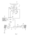
- FIG. 1 is a schematic view that shows the schematic configuration of a vehicle steering system according to an embodiment of the invention.
- the vehicle steering system 1 constitutes a so-called steer-by-wire system in which a steering member 2, such as a steering wheel, which is operated in multiple rotations, is not mechanically coupled to steered wheels 3.
- an operation of a steered system actuator 4 that is driven in response to a rotating operation of the steering member 2 is converted into a linear motion of a steered shaft 6 in the vehicle-width direction.
- the steered shaft 6 is supported by a housing 5.
- the linear motion of the steered shaft 6 is converted into steered motions of the right and left steered wheels 3.
- a vehicle is steered.
- the position of the steering member 2, which corresponds to the position of the steered wheels 3 at the time when the vehicle is travelling straight ahead, is set as a steering neutral position.
- the steered system actuator 4 includes, for example, an electric motor.
- the driving force of the electric motor (the rotational force of an output shaft) is converted into an axial linear motion of the steered shaft 6 by a ball screw mechanism provided for the steered shaft 6.
- the linear motion of the steered shaft 6 is transmitted to tie rods 7 coupled to respective ends of the steered shaft 6, and causes the pivot motions of knuckle arms 8.
- the steered wheels 3 supported by the knuckle arms 8 are steered.
- the steered shaft 6, the tie rods 7 and the knuckle arms 8 constitute a steered mechanism A used to steer the steered wheels 3.
- the housing 5 that supports the steered shaft 6 is fixed to a vehicle body B.
- the steering member 2 is coupled to a steering shaft 9 that is rotatably supported by the vehicle body B.
- a reaction motor 10 is fitted to the steering shaft 9.
- the reaction motor 10 is used to apply reaction force, which is transmitted from a road surface, or the like, to the steered wheels 3, to the steering member 2 as steering reaction force.
- the reaction motor 10 includes an electric motor, such as a brushless motor.
- the reaction motor 10 is accommodated in a housing 11 that is fixed to the vehicle body B.
- the vehicle steering system 1 includes a steering angle sensor 12 provided on the steering shaft 9.
- the steering angle sensor 12 is used to detect a steering angle ⁇ h of the steering member 2.
- a torque sensor 13 is provided on the steering shaft 9.
- the torque sensor 13 is used to detect a steering torque T applied to the steering member 2.
- the steering angle sensor 12 and the torque sensor 13 are accommodated in the housing 11.
- a rotation angle restriction mechanism 14 and a pair of strain gauges 15a, 15b are accommodated in the housing 11.
- the rotation angle restriction mechanism 14 restricts the rotation angle of the steering member 2.
- the strain gauges 15a, 15b serve as a steering direction detection unit that detects only a steering direction.
- the rotation angle restriction mechanism 14 has the function of restricting the rotation angle of an output shaft 24 of the steering shaft 9 within a restricted angular range.
- the steering shaft 9 serves as a rotary shaft of the steering member 2 that is rotationally operated.
- the steering member 2 is not subjected to restrictions from the steered mechanism A. Therefore, in order to prevent the steering member 2 from being operated beyond an operation limit of the steered mechanism A, the rotation angle restriction mechanism 14 restricts the rotation angle of the steering member 2 within the restricted angular range that corresponds to the operation limit.
- the strain gauges 15a, 15b detect the steering direction of the steering member 2 by detecting a strain of the rotation angle restriction mechanism 14 at one of the terminal ends of the restricted angular range of the rotation angle restriction mechanism 14.
- the vehicle steering system 1 includes a steered angle sensor 16 at the steered shaft 6.
- the steered angle sensor 16 is used to detect a steered angle ⁇ w (tire angle) of the steered wheels 3.
- a vehicle speed sensor 17 that detects a vehicle speed V is provided. Detection signals from these sensors 12, 13, 15 to 17 are input into an electronic control unit (ECU) 18 that serves as a control unit that includes a microcomputer.
- ECU electronice control unit
- the ECU 18 sets a target steered angle on the basis of the steering angle ⁇ h detected by the steering angle sensor 12 and the vehicle speed V detected by the vehicle speed sensor 17.
- the ECU 18 executes drive control (steered operation control) on the steered system actuator 4 via a drive circuit (not shown) incorporated in the ECU 18, on the basis of a deviation between the target steered angle and the steered angle ⁇ w detected by the steered angle sensor 16.
- the ECU 18 executes drive control (reaction control) on the reaction motor 10 via the drive circuit (not shown) incorporated in the ECU 18 such that an appropriate reaction force in a direction opposite to the direction in which the steering member 2 is steered is applied to the steering member 2 on the basis of the detection signals output from the sensors 12, 13, 15 to 17.
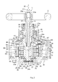
- the steering shaft 9 is rotatably supported by the tubular housing 11.
- One end of the steering shaft 9 protrudes from the housing 11, and the steering member 2 is coupled to the one end so as to be rotatable together with the steering shaft 9.
- the steering angle sensor 12, the torque sensor 13 and the reaction motor 10 are accommodated in the housing 11.
- the steering shaft 9 includes an input shaft 22 and the output shaft 24.
- the steering member 2 is coupled to one end 22a of the input shaft 22 (which corresponds to the above-described one end of the steering shaft 9) so as to be rotatable together with the input shaft 22.
- the output shaft 24 is coaxially coupled to the input shaft 22 via a torsion bar 23 such that torque is transmittable between the input shaft 22 and the output shaft 24.
- One end 23a of the torsion bar 23 is coupled to the input shaft 22 so as to be rotatable together with the input shaft 22.
- the other end 23b of the torsion bar 23 is coupled to the output shaft 24 so as to be rotatable together with the output shaft 24.
- the steering shaft 9 is rotatably supported by a first bearing 25, a second bearing 26 and a third bearing 27 that are retained by the housing 11.
- the first bearing 25 supports an axially intermediate portion of the input shaft 22 such that the input shaft 22 is rotatable.
- the second bearing 26 and the third bearing 27 support the output shaft 24 such that the output shaft 24 is rotatable.
- the second bearing 26 supports a portion of the output shaft 24, which is near one end 24a of the output shaft 24, such that the output shaft 24 is rotatable
- the third bearing 27 supports the other end 24b of the output shaft 24 such that the output shaft 24 is rotatable.
- the other end 22b of the input shaft 22 is inserted into a support hole 28 formed in the output shaft 24.
- the other end 22b of the input shaft 22 is rotatably supported by the inner periphery of the output shaft 24, which defines the support hole 28, via a fourth bearing 30.
- the housing 11 is formed by assembling a housing body 31 and an end wall 32 together.
- the housing body 31 has a tubular shape, and has one end 31a and the other end 31b.
- the end wall 32 that is part of the housing 11 has a generally plate shape, and closes the other end 31b of the housing body 31.
- the end wall 32 has a tubular portion 33 that protrudes in the axial direction from a portion of the end wall 32, which is near the radially outer portion of the end wall 32, and the tubular portion 33 is fitted to the inner periphery of the other end 31b of the housing body 31.
- An O-ring 34 is accommodated in an accommodation groove formed in the outer periphery of the tubular portion 33. The sealing performance at a joint between the housing body 31 and the tubular portion 33 is ensured by the O-ring 34.
- the end wall 32 is fixed to the other end 31b of the housing body 31 with, for example, fixing screws 35.
- the end wall 32 and a pressing plate 70 constitute a non-rotatable element (described later) of the rotation angle restriction mechanism 14.
- the end wall 32 is part of the housing 11.
- the rotation of the pressing plate 70 is restricted by the end wall 32 via an urging member 69 (described later).
- An oil seal 36 is interposed between the inner periphery of the one end 31a of the housing body 31 and the outer periphery of the input shaft 22 of the steering shaft 9, and seals a gap therebetween.
- the first bearing 25 is retained by a bearing retaining portion 37 formed in the inner periphery of the one end 31a of the housing body 31.
- the second bearing 26 is retained by a bearing retaining portion 38 formed in an axially intermediate portion of the housing body 31, and supports the outer periphery of a portion of the output shaft 24, which is near the one end 24a of the output shaft 24, such that the output shaft 24 is rotatable.
- the second bearing 26 includes an outer ring 39 and an inner ring 40.
- the outer ring 39 is fixedly fitted to the bearing retaining portion 38.
- the inner ring 40 is fitted to the outer periphery of the output shaft 24 so as to be rotatable together with the output shaft 24.
- One end face of the outer ring 39 of the second bearing 26 contacts a positioning step 41 formed at one end of the bearing retaining portion 38 of the housing body 31. This restricts movement of the outer ring 39 toward one side (toward the first bearing 25) in an axial direction X1 of the output shaft 24.
- One end face of the inner ring 40 of the second bearing 26 contacts a positioning step 42 formed in the outer periphery of the output shaft 24. This restricts movement of the inner ring 40 toward the other side (toward the third bearing 27) in the axial direction X1 of the output shaft 24.
- a circular center recess 43 and an annular recess 44 are formed in an inner wall face 32a of the end wall 32.
- the center recess 43 serves as a first recess.
- the annular recess 44 surrounds the center recess 43 and serves as a second recess.
- the depth of the center recess 43 is larger than the depth of the annular recess 44.
- the other end 24b of the output shaft 24 is inserted into the center recess 43.
- the third bearing 27 is retained by the inner periphery of the end wall 32, which defines the center recess 43, and supports the other end 24b of the output shaft 24 such that the output shaft 24 is rotatable.
- the third bearing 27 includes an outer ring 46 and an inner ring 47.
- the outer ring 46 is loosely fitted to the inner periphery of the end wall 32, which defines the center recess 43, so as to be axially movable.
- the inner ring 47 is fitted to the outer periphery of the other end 24b of the output shaft 24 so as to be rotatable together with the output shaft 24.
- One end face of the inner ring 47 of the third bearing 27 contacts a positioning step 48 formed in the outer periphery of the output shaft 24. This restricts movement of the inner ring 47 toward the one side (toward the second bearing 26) in the axial direction X1 of the output shaft 24.
- the elastic member 49 and a spacer 50 are accommodated in the center recess 43.
- the elastic member 49 is formed of a wave washer, and collectively applies an axial preload to the second bearing 26 and the third bearing 27.
- the spacer 50 serves as a preload application member, and is interposed between the elastic member 49 and the third bearing 27.
- the spacer 50 is formed of a circular plate or an annular plate as shown in FIG. 2 .
- the spacer 50 has an annular protrusion 51 such that the spacer 50 contacts neither the end face of the other end 24b of the output shaft 24 nor the end face of the inner ring 47 of the third bearing 27 and contacts only the end face of the outer ring 46.
- the elastic member 49 urges the outer ring 46 of the third bearing 27 via the annular protrusion 51 of the spacer 50 toward the one side in the axial direction X1 of the output shaft 24.
- the urging force is received by the positioning step 41 of the housing body 31 via the outer ring 46 of the third bearing 27, the inner ring 47 of the third bearing 27, the positioning step 48 of the output shaft 24, the positioning step 42 of the output shaft 24, the inner ring 40 of the second bearing 26 and the outer ring 39 of the second bearing 26.
- the torque sensor 13 is arranged between the first bearing 25 and the second bearing 26 in the housing 11.
- the torque sensor 13 may be, for example, a torque sensor that uses a Hall IC (magnetic sensor).
- the ECU 18 is configured to calculate a steering torque input into the steering shaft 9 on the basis of a signal from the torque sensor 13.
- the reaction motor 10 includes a rotor 61 and a stator 62.
- the rotor 61 is coupled to the output shaft 24 so as to be rotatable together with the output shaft 24.
- the stator 62 concentrically surrounds the rotor 61, and is fixed to the inner periphery of the housing body 31.
- the rotor 61 includes a rotor core 63 and a permanent magnet 64.
- the rotor core 63 is rotatable together with the output shaft 24.
- the permanent magnet 64 is coupled to the rotor core 63 so as to be rotatable together with the rotor core 63.
- the rotor core 63 has a tubular first portion 65 and a second portion 66.
- the first portion 65 concentrically surrounds the output shaft 24.
- the second portion 66 is coupled to the output shaft 24 so as to be rotatable together with the output shaft 24.
- the permanent magnet 64 is coupled to the outer periphery of the first portion 65 so as to be rotatable together with the first portion 65.
- the second portion 66 constitutes a rotatable element (described later) of the rotation angle restriction mechanism 14.
- the rotor core 63 that has the first portion 65 and the second portion 66 is formed integrally with the output shaft 24 from a single material.
- a rotor core formed separately from the output shaft 24 may be fixedly coupled to the output shaft 24.
- the steering angle sensor 12 is arranged between the second portion 66 and the second bearing 26.
- the steering angle sensor 12 is formed of, for example, a resolver.
- the steering angle sensor 12 includes a resolver rotor 67 and a resolver stator 68.
- the resolver rotor 67 is coupled to the output shaft 24 so as to be rotatable together with the output shaft 24.
- the resolver stator 68 is fixed to the inner periphery of the housing body 31, and surrounds the resolver rotor 67.
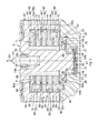
- FIG. 3 is a partially enlarged sectional view of the rotation angle restriction mechanism 14 and its surroundings in FIG. 2 . Almost all the elements of the rotation angle restriction mechanism 14 are arranged in a space on the radially inner side of the first portion 65 of the rotor core 63 of the rotor 61.
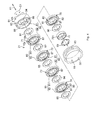
- the rotation angle restriction mechanism 14 includes the end wall 32 of the housing 11, a plurality of plate elements 71 to 75 and the second portion 66 of the rotor core 63.
- the end wall 32 of the housing 11 serves as the non-rotatable element.
- the plate elements 71 to 75 are coaxially supported by the output shaft 24 of the steering shaft 9 that serves as the rotary shaft of the steering member 2.
- the plate elements 71 to 75 are rotatable with respect to the output shaft 24 and are movable in the axial direction X1.
- the second portion 66 of the rotor core 63 serves as the rotatable element.
- the end wall 32 that serves as the non-rotatable element and the second portion 66 that serves as the rotatable element are arranged on respective sides of the plate elements 71 to 75 in the axial direction X1.
- the rotation angle restriction mechanism 14 includes a plurality of coupling elements 80 that couple adjacent elements, among the non-rotatable element (end wall 32), the plate elements 71 to 75 and the rotatable element (second portion 66), so as to restrict an amount of relative rotation between the adjacent elements.
- the rotation angle restriction mechanism 14 includes a plurality of friction plates 91 to 96 and a protruding portion 701. The friction plates 91 to 96 serve as a plurality of friction application elements each of which applies friction resistance to relative rotation between the adjacent elements.
- the protruding portion 701 serves as an axial movement restricting element that restricts the amount of movement of each of the plate elements 71 to 75 in the axial direction X1 to a predetermined amount so as to restrict inclination of each of the plate elements 71 to 75.
- each of the coupling elements 80 is formed of a pin-shaped protrusion 81 and a closed-end engagement groove 82 or closed-end engagement groove 83.
- the protrusion 81 is provided at one of the corresponding adjacent elements, and protrudes in the axial direction X1.
- the engagement groove 82 or engagement groove 83 is formed in the other one of corresponding adjacent elements such that the protrusion 81 engages with the engagement groove 82 or engagement groove 83, and extends in the circumferential direction C 1.
- each of the protrusions 81 engages with one of restricting portions 82a or one of restricting portions 83a, which are respective ends of a corresponding one of the engagement grooves 82, 83.
- an amount of relative rotation between any adjacent elements is restricted.
- each of the plate elements 71 to 75 is formed of an annular plate, and is arranged between the first portion 65 and the output shaft 24.
- the plate elements 72 to 75 are formed of common members, and the plate element 71 differs from the remaining plate elements 72 to 75 in that the strain gauges 15a, 15b that serve as the steering direction detection unit are arranged.
- the plate elements 71 to 75 are supported on an outer periphery 85a of a tubular member 85 (for example, a plain bearing, such as a metal bush) so as to be rotatable about a first rotation center L1 and axially movable.
- the tubular member 85 is fitted to the outer periphery of the output shaft 24 so as to be rotatable together with the output shaft 24.
- the plate elements 71 to 75 are rotatable relative to the output shaft 24 and the first portion 65.
- the protrusion 81 is formed on one end face of each of the plate elements 71 to 75 so as to protrude therefrom, and the engagement groove 82 is formed so as to extend in the circumferential direction C1 in a region in which the protrusion 81 is not formed.
- the end wall 32 (non-rotatable element) of the housing 11 has the closed-end engagement groove 83 that extends in the circumferential direction C1.
- each of the protrusions 81 is formed separately from a corresponding one of the plate elements 71 to 75, and part of each of the protrusions 81 is inserted and fixedly fitted in a fixing hole 86 of a corresponding one of the plate elements 71 to 75.
- Each protrusion 81 may be formed integrally with the corresponding one of the plate elements 71 to 75 from a single material.
- An annular receiving recess 87 is formed in at least one end face (end face from which each of the protrusions 81 protrudes in the present embodiment) of each of the plate elements 71 to 75.
- each receiving recess 87 receives a corresponding one of the friction plates 92 to 96.
- the outer periphery of each of the friction plates 92 to 96 is rotatably supported by the peripheral wall face of the corresponding one of the receiving recesses 87.
- an annular receiving recess 88 is formed in the second portion 66 of the rotor core 63 of the rotor 61.
- the outer periphery of the friction plate 91 is rotatably supported by the peripheral wall face of the receiving recess 88.
- the protrusion 81 formed at the second portion 66 is fitted in the closed-end engagement groove 82 formed in the plate element 71 so as to be slidable in the circumferential direction C1.
- the protrusions 81 respectively formed on the plate elements 71 to 74 are respectively slidably fitted in the corresponding engagement grooves 82 respectively formed in the adjacent plate elements 72 to 75.
- the protrusion 81 formed on the plate element 75 is slidably fitted in the engagement groove 83 formed in the end wall 32 (non-rotatable element) of the housing 11.
- the range in which the engagement groove 82 is arranged in the circumferential direction C1 may be set as follows: the movement range of each protrusion 81 that engages with the engagement groove 82 of a corresponding one of the plate elements 71 to 75 (range in which the protrusion 81 moves between the restricting portions 82a at respective ends of the engagement groove 82) is formed such that the relative rotation angle between the adjacent elements becomes ⁇ 1 As shown in FIG. 6A and FIG. 6B , the range in which the engagement groove 82 is arranged in the circumferential direction C1 may be set as follows: the movement range of each protrusion 81 that engages with the engagement groove 82 of a corresponding one of the plate elements 71 to 75 (range in which the protrusion 81 moves between the restricting portions 82a at respective ends of the engagement groove 82) is formed such that the relative rotation angle between the adjacent elements becomes ⁇ 1 As shown in FIG.
- the range in which the engagement groove 83 is arranged in the circumferential direction C1 may be set as follows: the movement range of the protrusion 81, which engages with the engagement groove 83 of the end wall 32 (non-rotatable element) (range in which the protrusion 81 moves between the restricting portions 83a at respective ends of the engagement groove 83) is formed such that the relative rotation angle between the adjacent elements becomes ⁇ 2.
- the plate elements 71 to 75 are the common ones, and the arrangement range of the engagement groove 83 of the end wall 32 is made different from the arrangement range of each of the engagement grooves 82 of the plate elements 71 to 75. Thus, it is possible to easily set the restriction range of the rotation amount of the steering shaft 9 while achieving cost reduction. Note that, ⁇ 1 may be equal to ⁇ 2.
- the strain gauges 15a, 15b which serve as the steering direction detection unit, are arranged on the end face of the plate element 71, the end face being on the side on which the protrusion 81 formed on the plate element 71 protrudes.
- the strain gauge 15a is arranged near one of the restricting portions 82a of the engagement groove 82 of the plate element 71
- the strain gauge 15b is arranged near the other one of the restricting portions 82a of the engagement groove 82 of the plate element 71.
- the protrusion 81 engages with one of the restricting portions 82a of the engagement groove 82 of the plate element 71.
- a strain occurs near the one of the restricting portions 82a, and the strain gauge 15a detects the strain.
- the ECU 18 detects the steering direction, and determines, for example, that steering to the left is performed.
- the protrusion 81 engages with the other one of the restricting portions 82a of the engagement groove 82 of the plate element 71.
- the strain gauge 15b detects the strain.
- the ECU 18 detects the steering direction, and determines, for example, that steering to the right is performed.
- each of the friction plates 91 to 96 is interposed between corresponding two adjacent elements such that friction resistance against relative rotation between the corresponding two adjacent elements is applied to the corresponding two adjacent elements.
- the friction plate 91 is interposed between the second portion 66 (rotatable element) and the plate element 71, and applies friction resistance against the relative rotation between the elements 66, 71 to the elements 66, 71.
- the friction plates 92 to 95 are respectively interposed between the adjacent plate elements 71, 72, between the adjacent plate elements 72, 73, between the adjacent plate elements 73, 74 and between the adjacent plate elements 74, 75, and apply friction resistance against relative rotation between the corresponding adjacent two of the plate elements 71 to 75 to the corresponding adjacent two of the plate elements 71 to 75.
- the friction plate 96 is interposed between the plate element 75 and the pressing plate 70, and applies friction resistance against relative rotation between the plate element 75 and the pressing plate 70 to the plate element 75 and the pressing plate 70.
- the urging member 69 and the pressing plate 70 are accommodated and retained in the annular recess 44 of the inner wall face 32a of the end wall 32 of the housing 11.
- the urging member 69 and the pressing plate 70 each have an annular shape, and surround the output shaft 24.
- a wave washer is used as the urging member 69.
- the urging member 69 is interposed between a bottom 44a of the annular recess 44 and the pressing plate 70.
- the pressing plate 70 has, for example, an annular protruding portion 701 that serves as an axial movement restricting element and that protrudes from its outer periphery in the axial direction.
- the annular protruding portion 701 is formed integrally with the pressing plate 70 from a single material.
- the outer periphery of the annular protruding portion 701 is supported by a peripheral wall face 44b of the annular recess 44 so as to be movable in the axial direction X1.
- the annular protruding portion 701 surrounds the urging member 69 formed of the wave washer.
- the urging member 69 elastically urges the pressing plate 70 toward the friction plate 96.
- the urging member 69 elastically holds a laminated unit between the pressing plate 70 (non-rotatable element) and the second portion 66 (rotatable element) of the rotor 61.
- the laminated unit includes the plate elements 71 to 75 and the friction plates 91 to 96.
- the friction plates 91 to 96 serve as the friction resistance application elements. That is, the urging member 69 collectively applies an axial preload to the plate elements 71 to 75 and friction plates 91 to 96 of the laminated unit.
- the friction plates 91 to 96 are set so as to be able to apply friction resistance having a desired magnitude to members that contact with the friction plates 91 to 96.
- a clearance S is formed between the protruding portion 701 and the end wall 32 (specifically, the bottom 44a of the annular recess 44).
- the amount of the clearance S is set to a predetermined amount (for example, 0.1 mm).
- FIG. 7 is a flowchart that shows the flow of control that is executed by the ECU 18 in association with steered operation control.
- step S2 When there is no failure (NO in step S2), the process shifts into a normal mode. In the normal mode, drive control (steered operation control) is executed on the steered system actuator 4 on the basis of the steering angle ⁇ h detected by the steering angle sensor 12 (step S3). When there is a failure (YES in step S2), the process shifts into a failure mode. In the failure mode, on the basis of the steering direction detected by the strain gauge 15a (or strain gauge 15b), drive control (steered operation control) is executed on the steered system actuator 4 such that the steered system actuator 4 is driven in the corresponding steered direction while the value detected by one of the strain gauges 15a, 15b is larger than or equal to a predetermined value (step S4).
- drive control steerered operation control
- strain gauges 15a, 15b detects the strain to detect the steering direction. By executing drive control on the steered system actuator 4 on the basis of the detected steering direction, it is possible to perform steering, thereby achieving fail safe. Because the simple and inexpensive strain gauges 15a, 15b are used as the steering direction detection unit, it is possible to reduce manufacturing cost.
- the ECU 18 is able to easily detect the steering direction on the basis of binary determination as to whether a value output from one of the strain gauges 15a, 15b exceeds a predetermined value.
- adjacent elements among the non-rotatable element (end wall 32), the rotatable element (second portion 66) and the plate elements 71 to 74 of the rotation angle restriction mechanism 14 are coupled by the corresponding coupling element 80 such that the amount of relative rotation between the adjacent elements is restricted. Therefore, regardless of which of the non-rotatable element (end wall 32), the rotatable element (second portion 66) and the plate elements 71 to 75 has the strain gauges 15a, 15b, it is possible to detect the steering direction by detecting a strain at the terminal ends of the restricted angular range.
- the strain gauges 15a, 15b are arranged at the plate element 71 in which the restricting portions 82a are formed, and a strain that occurs in the plate element 71 is detected.
- the non-rotatable element (end wall 32) and the rotatable element (second portion 66) are arranged on respective sides of the plate elements 71 to 75, which are coaxially supported by the rotary shaft (output shaft 24) of the steering member 2, in the axial direction X1. Therefore, it is possible to arrange the elements of the rotation angle restriction mechanism 14 in a compact space, and it is possible to achieve a reduction in size. In addition, by accommodating the reaction motor 10 that applies steering reaction force to the steering member 2 and the rotation angle restriction mechanism 14 inside the same housing 11, it is possible to achieve simplification of the structure and a reduction in size in the steer-by-wire vehicle steering system 1.
- the strain gauges 15a, 15b are arranged at the plate element 71.
- the strain gauges may be arranged at any one of the other plate elements 72 to 75.
- a strain gauge 15c may be arranged at any element (for example, the plate element 71) at which the protrusion 81 that serves as the restricted portion is provided.
- the only one strain gauge 15c needs to be arranged at the protrusion 81 or near the protrusion 81. Therefore, it is possible to simplify the structure.
- the sign of the value output from the strain gauge 15c varies depending on which one of the restricting portions 82a the protrusion 81 contacts. Therefore, it is possible to detect the steering direction.
- lightening portions 77a, 77b may be formed near the strain gauges 15a, 15b, respectively.
- the lightening portions 77a, 77b near the strain gauges 15a, 15b, respectively, it is possible to increase the amount of strain near each of the strain gauges 15a, 15b.
- it is possible to reliably detect a strain thereby improving the detection accuracy.
- FIG. 10 shows another embodiment of the invention.
- a plate element 75A which is one of the endmost plate elements (in the axial direction X1) and which faces the end wall 32 that serves as the non-rotatable element, is supported by the end wall 32 so as to be rotatable about a second rotation center L2 that is offset from the first rotation center L1.
- the first rotation center L1 is the rotation center of each of the remaining plate elements 71 to 74 except the plate element 75A which is one of the endmost plate elements, and corresponds to the central axis of the output shaft 24 that serves as the rotary shaft of the steering member 2.
- a support shaft 78 that protrudes from the end face of the plate element 75A that faces the end wall 32 is rotatably fitted to a support hole 32b formed in the inner wall face 32a of the end wall 32.
- the second rotation center L2 corresponds to the central axis of the support shaft 78.
- a protrusion 810 that serves as a restricted portion and that protrudes from the end wall 32 toward the plate element 75A is accommodated in a recess 830 formed in the plate element 75A so as to be engageable with a predetermined play in the circumferential direction C1.
- the engagement groove 82 with which the protrusion 81 of the adjacent plate element 74 engages is formed in the plate element 75A.
- a pair of restricting portions 831, 832 is formed within the recess 830 at the respective terminal ends of the restricted angular range.
- the protrusion 810 contacts one of the restricting portions 831, 832 as the plate element 75A eccentrically oscillates.
- a strain gauge 15d that serves as the steering direction detection unit is arranged on the side face of the protrusion 810. Because the direction in which the protrusion 810 deforms is different between the case where the protrusion 810 contacts the restricting portion 831 and the case where the protrusion 810 contacts the restricting portion 832, the sign of the value output from the strain gauge 15d varies depending on whether the protrusion 810 contacts the restricting portion 831 or the restricting portion 832. As a result, it is possible to detect the steering direction even with the use of the single strain gauge 15d.
- the plate element 75A which is one of the endmost plate elements and which faces the non-rotatable element (end wall 32), rotates eccentrically with respect to the remaining plate elements 71 to 74.
- the plate element 75A which is one of the endmost plate elements and which faces the non-rotatable element (end wall 32), rotates eccentrically with respect to the remaining plate elements 71 to 74.
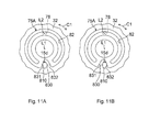
- the protrusion 810 that serves as the restricted portion contacts the restricting portion 831 in the recess 830 as shown in FIG. 11A
- the protrusion 810 that serves as the restricted portion contacts the restricting portion 832 in the recess 830 as shown in FIG. 11B .
- strain gauge 15d arranged at the protrusion 810 provided at the plate element 75A.
- strain gauges may be respectively provided at the restricting portions 831, 832.
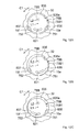
- FIG. 12A to FIG. 12C show further another embodiment of the invention.
- the present embodiment differs from the embodiment shown in FIG. 10 in the following point. That is, a plate element 75B which is one of the endmost plate elements is accommodated in an annular recess 835 formed in the end wall 32 that serves as the non-rotatable element so as to be engageable with a play in the circumferential direction C1.
- a circular columnar support shaft 78B that protrudes from the plate element 75B is fitted in a circular support hole of the end wall 32, and the plate element 75B is supported so as to be rotatable about the second rotation center L2 that is the central axis of the support shaft 78B. That is, the central axis of the support shaft 78B coincides with the second rotation center L2 that is the rotation center of the plate element 75B which is one of the endmost plate elements, and the second rotation center L2 is offset from the first rotation center L1 of the remaining plate elements 71 to 74.
- the protrusion 81 that protrudes from the adjacent plate element 74 is engaged with an engagement groove 821 formed in the plate element 75B.
- a pair of restricting portions 836, 837 is formed on an inner periphery 835a of the annular recess 835, and part of an outer periphery 75B1 of the plate element 75B constitutes restricted portions 751, 752.
- a pair of strain gauges 15e, 15f that serve as the steering direction detection unit is arranged on the inner periphery 835a of the annular recess 835.
- the strain gauges 15e, 15f are respectively arranged at the restricting portions 836, 837 or near the restricting portions 836, 837.
- the plate element 75B which is one of the endmost plate elements and which faces the non-rotatable element (end wall 32), rotates eccentrically with respect to the remaining plate elements 71 to 74.
- the corresponding restricted portion 751 contacts the restricting portion 836, and the strain gauge 15e detects a strain that occurs in the restricting portion 836.
- the corresponding restricted portion 752 contacts the restricting portion 837, and the strain gauge 15f detects a strain that occurs in the restricting portion 837.
- the amount of relative rotation between the non-rotatable element (end wall 32) and the plate element 75B, which is one of the endmost plate elements, is restricted. Therefore, it is possible to detect a strain with the use of a corresponding one of the strain gauges 15e, 15f arranged on the inner periphery 835a of the annular recess 835 of the end wall 32.
- a pair of strain gauges respectively provided at the restricted portions 751, 752 may be used.
- the invention is not limited to the above-described embodiments.
- the inner peripheries of the plate elements 71 to 75 are supported by the outer periphery of the tubular member 85 fitted to the outer periphery of the steering shaft 9 (output shaft 24).
- the inner peripheries of the plate elements 71 to 75 may be directly supported by the steering shaft 9 (output shaft 24).
- Each friction resistance application element may be a friction layer that coats at least one of facing surfaces of adjacent elements.
- the urging member 69 and the pressing plate 70 may be interposed between the second portion 66 that serves as the rotatable element and the plate element 71.
- the plate elements 71 to 75 may be retained by a plain bearing retained on the inner periphery of the first portion 65 of the rotor 61.
Landscapes
- Engineering & Computer Science (AREA)
- Chemical & Material Sciences (AREA)
- Combustion & Propulsion (AREA)
- Transportation (AREA)
- Mechanical Engineering (AREA)
- Power Steering Mechanism (AREA)
- Steering Control In Accordance With Driving Conditions (AREA)
Abstract
Description
- The invention relates to a vehicle steering system.
- Japanese Patent Application Publication No.
10-278826 JP 10-278826 A JP 10-278826 A 2004-90784 JP 2004-90784 A JP 2004-90784 A - According to
JP 10-278826 A JP 2004-90784 A - The invention provides a vehicle steering system that is able to detect a steering direction with a low-cost configuration, in the event of a malfunction in a steering angle sensor.
- According to a feature of an example of the invention, in a vehicle steering system in which a steering member and a steered wheel are not mechanically coupled to each other, there are provided: a steering angle sensor that detects a steering angle of the steering member; a steering direction detection unit that detects only a steering direction of the steering member; a steered system actuator that drives the steered wheel; a rotation angle restriction mechanism that restricts a rotation angle of the steering member within a restricted angular range; and a control unit that has a normal mode in which drive control is executed on the steered system actuator on the basis of the steering angle detected by the steering angle sensor and a failure mode in which, when there is a malfunction in the steering angle sensor, drive control is executed on the steered system actuator on the basis of the steering direction detected by the steering direction detection unit, and the steering direction detection unit includes a strain gauge that detects the steering direction by detecting a strain that occurs in the rotation angle restriction mechanism at any one of a pair of terminal ends of the restricted angular range.
- The foregoing and further objects, features and advantages of the invention will become apparent from the following description of example embodiments with reference to the accompanying drawings, wherein like numerals are used to represent like elements and wherein:
-
FIG. 1 is a schematic view that shows the schematic configuration of a vehicle steering system according to an embodiment of the invention; -
FIG. 2 is a sectional view of a housing that accommodates a reaction motor, a rotation angle restriction mechanism that restricts the rotation angle of a steering member, and the like; -
FIG. 3 is a partially enlarged sectional view of the rotation angle restriction mechanism and its surroundings inFIG. 2 ; -
FIG. 4 is an exploded perspective view of the rotation angle restriction mechanism; -
FIG. 5 is a sectional view of each of plate elements of the rotation angle restriction mechanism; -
FIG. 6A is a front view of the plate element, for illustrating a movement range of a protrusion that engages with an engagement groove of the plate element at which strain gauges are arranged; -
FIG. 6B is a front view of each plate element, for illustrating a movement range of a corresponding protrusion that engages with an engagement groove of the plate element at which no strain gauge is arranged; -
FIG. 6C is a front view of the plate element, for illustrating a movement range of a protrusion that engages with an engagement groove of an end wall that serves as a non-rotatable element; -
FIG. 7 is a flowchart that shows the flow of main control that is executed by an ECU; -
FIG. 8 is a sectional view of a plate element at which a strain gauge of a rotation angle restriction mechanism is arranged in another embodiment of the invention; -
FIG. 9 is a front view of a plate element at which strain gauges and lightening portions are arranged in another embodiment of the invention; -
FIG. 10 is an exploded perspective view of an end wall that serves as a non-rotatable element and some of plate elements according to another embodiment of the invention; -
FIG. 11A and FIG. 11B are front views of one of endmost plate elements and an end wall that serves as a non-rotatable element, whereinFIG. 11A shows a state where a protrusion is engaged with one of restricting portions in a recess, andFIG. 11B shows a state where the protrusion is engaged with the other one of the restricting portions in the recess; and -
FIG. 12A to FIG. 12C are schematic front views of one of endmost plate elements and an end wall that serves as a non-rotatable element according to another embodiment of the invention, whereinFIG. 12A shows a state where rotation of the one of the endmost plate elements is not restricted,FIG. 12B shows a state where one of restricted portions on the outer periphery of the one of the endmost plate elements is engaged with one of restricting portions of an annular recess, andFIG. 12C shows a state where the other one of the restricted portions on the outer periphery of the one of the endmost plate elements is engaged with the other one of the restricting portions of the annular recess. - Hereinafter, embodiments of the invention will be described with reference to the accompanying drawings.
-
FIG. 1 is a schematic view that shows the schematic configuration of a vehicle steering system according to an embodiment of the invention. As shown inFIG. 1 , thevehicle steering system 1 constitutes a so-called steer-by-wire system in which asteering member 2, such as a steering wheel, which is operated in multiple rotations, is not mechanically coupled to steeredwheels 3. - In the
vehicle steering system 1, an operation of a steeredsystem actuator 4 that is driven in response to a rotating operation of thesteering member 2 is converted into a linear motion of a steeredshaft 6 in the vehicle-width direction. The steeredshaft 6 is supported by ahousing 5. The linear motion of the steeredshaft 6 is converted into steered motions of the right and left steeredwheels 3. Thus, a vehicle is steered. The position of thesteering member 2, which corresponds to the position of the steeredwheels 3 at the time when the vehicle is travelling straight ahead, is set as a steering neutral position. - The steered
system actuator 4 includes, for example, an electric motor. The driving force of the electric motor (the rotational force of an output shaft) is converted into an axial linear motion of the steeredshaft 6 by a ball screw mechanism provided for the steeredshaft 6. The linear motion of the steeredshaft 6 is transmitted totie rods 7 coupled to respective ends of the steeredshaft 6, and causes the pivot motions ofknuckle arms 8. Thus, the steeredwheels 3 supported by theknuckle arms 8 are steered. - The steered
shaft 6, thetie rods 7 and theknuckle arms 8 constitute a steered mechanism A used to steer the steeredwheels 3. Thehousing 5 that supports the steeredshaft 6 is fixed to a vehicle body B. Thesteering member 2 is coupled to asteering shaft 9 that is rotatably supported by the vehicle body B.A reaction motor 10 is fitted to thesteering shaft 9. Thereaction motor 10 is used to apply reaction force, which is transmitted from a road surface, or the like, to the steeredwheels 3, to thesteering member 2 as steering reaction force. Thereaction motor 10 includes an electric motor, such as a brushless motor. Thereaction motor 10 is accommodated in ahousing 11 that is fixed to the vehicle body B. - The
vehicle steering system 1 includes asteering angle sensor 12 provided on thesteering shaft 9. Thesteering angle sensor 12 is used to detect a steering angle θh of thesteering member 2. Atorque sensor 13 is provided on thesteering shaft 9. Thetorque sensor 13 is used to detect a steering torque T applied to thesteering member 2. Thesteering angle sensor 12 and thetorque sensor 13 are accommodated in thehousing 11. In addition, a rotationangle restriction mechanism 14 and a pair ofstrain gauges housing 11. The rotationangle restriction mechanism 14 restricts the rotation angle of the steeringmember 2. Thestrain gauges - The rotation
angle restriction mechanism 14 has the function of restricting the rotation angle of anoutput shaft 24 of thesteering shaft 9 within a restricted angular range. The steeringshaft 9 serves as a rotary shaft of the steeringmember 2 that is rotationally operated. In the steer-by-wirevehicle steering system 1 in the present embodiment, the steeringmember 2 is not subjected to restrictions from the steered mechanism A. Therefore, in order to prevent thesteering member 2 from being operated beyond an operation limit of the steered mechanism A, the rotationangle restriction mechanism 14 restricts the rotation angle of the steeringmember 2 within the restricted angular range that corresponds to the operation limit. - In the event of a failure, that is, when there is a malfunction in the
steering angle sensor 12, thestrain gauges member 2 by detecting a strain of the rotationangle restriction mechanism 14 at one of the terminal ends of the restricted angular range of the rotationangle restriction mechanism 14. In addition, thevehicle steering system 1 includes a steeredangle sensor 16 at the steeredshaft 6. The steeredangle sensor 16 is used to detect a steered angle θw (tire angle) of the steeredwheels 3. In addition to these sensors, avehicle speed sensor 17 that detects a vehicle speed V is provided. Detection signals from thesesensors - The
ECU 18 sets a target steered angle on the basis of the steering angle θh detected by thesteering angle sensor 12 and the vehicle speed V detected by thevehicle speed sensor 17. TheECU 18 executes drive control (steered operation control) on the steeredsystem actuator 4 via a drive circuit (not shown) incorporated in theECU 18, on the basis of a deviation between the target steered angle and the steered angle δw detected by the steeredangle sensor 16. - In addition, the
ECU 18 executes drive control (reaction control) on thereaction motor 10 via the drive circuit (not shown) incorporated in theECU 18 such that an appropriate reaction force in a direction opposite to the direction in which thesteering member 2 is steered is applied to the steeringmember 2 on the basis of the detection signals output from thesensors - As shown in
FIG. 2 , the steeringshaft 9 is rotatably supported by thetubular housing 11. One end of thesteering shaft 9 protrudes from thehousing 11, and the steeringmember 2 is coupled to the one end so as to be rotatable together with thesteering shaft 9. Thesteering angle sensor 12, thetorque sensor 13 and thereaction motor 10 are accommodated in thehousing 11. - The steering
shaft 9 includes aninput shaft 22 and theoutput shaft 24. The steeringmember 2 is coupled to oneend 22a of the input shaft 22 (which corresponds to the above-described one end of the steering shaft 9) so as to be rotatable together with theinput shaft 22. Theoutput shaft 24 is coaxially coupled to theinput shaft 22 via atorsion bar 23 such that torque is transmittable between theinput shaft 22 and theoutput shaft 24. Oneend 23a of thetorsion bar 23 is coupled to theinput shaft 22 so as to be rotatable together with theinput shaft 22. Theother end 23b of thetorsion bar 23 is coupled to theoutput shaft 24 so as to be rotatable together with theoutput shaft 24. - The steering
shaft 9 is rotatably supported by afirst bearing 25, asecond bearing 26 and athird bearing 27 that are retained by thehousing 11. Thefirst bearing 25 supports an axially intermediate portion of theinput shaft 22 such that theinput shaft 22 is rotatable. Thesecond bearing 26 and thethird bearing 27 support theoutput shaft 24 such that theoutput shaft 24 is rotatable. Specifically, thesecond bearing 26 supports a portion of theoutput shaft 24, which is near oneend 24a of theoutput shaft 24, such that theoutput shaft 24 is rotatable, and thethird bearing 27 supports theother end 24b of theoutput shaft 24 such that theoutput shaft 24 is rotatable. - The
other end 22b of theinput shaft 22 is inserted into asupport hole 28 formed in theoutput shaft 24. Theother end 22b of theinput shaft 22 is rotatably supported by the inner periphery of theoutput shaft 24, which defines thesupport hole 28, via afourth bearing 30. - The
housing 11 is formed by assembling ahousing body 31 and anend wall 32 together. Thehousing body 31 has a tubular shape, and has oneend 31a and theother end 31b. Theend wall 32 that is part of thehousing 11 has a generally plate shape, and closes theother end 31b of thehousing body 31. - Specifically, the
end wall 32 has atubular portion 33 that protrudes in the axial direction from a portion of theend wall 32, which is near the radially outer portion of theend wall 32, and thetubular portion 33 is fitted to the inner periphery of theother end 31b of thehousing body 31. An O-ring 34 is accommodated in an accommodation groove formed in the outer periphery of thetubular portion 33. The sealing performance at a joint between thehousing body 31 and thetubular portion 33 is ensured by the O-ring 34. Theend wall 32 is fixed to theother end 31b of thehousing body 31 with, for example, fixing screws 35. - The
end wall 32 and a pressing plate 70 (described later) constitute a non-rotatable element (described later) of the rotationangle restriction mechanism 14. Theend wall 32 is part of thehousing 11. The rotation of thepressing plate 70 is restricted by theend wall 32 via an urging member 69 (described later). Anoil seal 36 is interposed between the inner periphery of the oneend 31a of thehousing body 31 and the outer periphery of theinput shaft 22 of thesteering shaft 9, and seals a gap therebetween. Thefirst bearing 25 is retained by abearing retaining portion 37 formed in the inner periphery of the oneend 31a of thehousing body 31. - The
second bearing 26 is retained by abearing retaining portion 38 formed in an axially intermediate portion of thehousing body 31, and supports the outer periphery of a portion of theoutput shaft 24, which is near the oneend 24a of theoutput shaft 24, such that theoutput shaft 24 is rotatable. Thesecond bearing 26 includes anouter ring 39 and aninner ring 40. Theouter ring 39 is fixedly fitted to thebearing retaining portion 38. Theinner ring 40 is fitted to the outer periphery of theoutput shaft 24 so as to be rotatable together with theoutput shaft 24. - One end face of the
outer ring 39 of thesecond bearing 26 contacts apositioning step 41 formed at one end of thebearing retaining portion 38 of thehousing body 31. This restricts movement of theouter ring 39 toward one side (toward the first bearing 25) in an axial direction X1 of theoutput shaft 24. One end face of theinner ring 40 of thesecond bearing 26 contacts apositioning step 42 formed in the outer periphery of theoutput shaft 24. This restricts movement of theinner ring 40 toward the other side (toward the third bearing 27) in the axial direction X1 of theoutput shaft 24. - A
circular center recess 43 and anannular recess 44 are formed in aninner wall face 32a of theend wall 32. Thecenter recess 43 serves as a first recess. Theannular recess 44 surrounds thecenter recess 43 and serves as a second recess. The depth of thecenter recess 43 is larger than the depth of theannular recess 44. Theother end 24b of theoutput shaft 24 is inserted into thecenter recess 43. Thethird bearing 27 is retained by the inner periphery of theend wall 32, which defines thecenter recess 43, and supports theother end 24b of theoutput shaft 24 such that theoutput shaft 24 is rotatable. - The
third bearing 27 includes anouter ring 46 and aninner ring 47. Theouter ring 46 is loosely fitted to the inner periphery of theend wall 32, which defines thecenter recess 43, so as to be axially movable. Theinner ring 47 is fitted to the outer periphery of theother end 24b of theoutput shaft 24 so as to be rotatable together with theoutput shaft 24. One end face of theinner ring 47 of thethird bearing 27 contacts apositioning step 48 formed in the outer periphery of theoutput shaft 24. This restricts movement of theinner ring 47 toward the one side (toward the second bearing 26) in the axial direction X1 of theoutput shaft 24. - An
elastic member 49 and aspacer 50 are accommodated in thecenter recess 43. Theelastic member 49 is formed of a wave washer, and collectively applies an axial preload to thesecond bearing 26 and thethird bearing 27. Thespacer 50 serves as a preload application member, and is interposed between theelastic member 49 and thethird bearing 27. Thespacer 50 is formed of a circular plate or an annular plate as shown inFIG. 2 . Thespacer 50 has anannular protrusion 51 such that thespacer 50 contacts neither the end face of theother end 24b of theoutput shaft 24 nor the end face of theinner ring 47 of thethird bearing 27 and contacts only the end face of theouter ring 46. Theelastic member 49 urges theouter ring 46 of thethird bearing 27 via theannular protrusion 51 of thespacer 50 toward the one side in the axial direction X1 of theoutput shaft 24. - The urging force is received by the
positioning step 41 of thehousing body 31 via theouter ring 46 of thethird bearing 27, theinner ring 47 of thethird bearing 27, thepositioning step 48 of theoutput shaft 24, thepositioning step 42 of theoutput shaft 24, theinner ring 40 of thesecond bearing 26 and theouter ring 39 of thesecond bearing 26. Thus, it is possible to collectively apply an axial preload to thesecond bearing 26 and thethird bearing 27. - The
torque sensor 13 is arranged between thefirst bearing 25 and thesecond bearing 26 in thehousing 11. Thetorque sensor 13 may be, for example, a torque sensor that uses a Hall IC (magnetic sensor). TheECU 18 is configured to calculate a steering torque input into thesteering shaft 9 on the basis of a signal from thetorque sensor 13. - The
reaction motor 10 includes arotor 61 and astator 62. Therotor 61 is coupled to theoutput shaft 24 so as to be rotatable together with theoutput shaft 24. Thestator 62 concentrically surrounds therotor 61, and is fixed to the inner periphery of thehousing body 31. Therotor 61 includes arotor core 63 and apermanent magnet 64. Therotor core 63 is rotatable together with theoutput shaft 24. Thepermanent magnet 64 is coupled to therotor core 63 so as to be rotatable together with therotor core 63. - The
rotor core 63 has a tubularfirst portion 65 and asecond portion 66. Thefirst portion 65 concentrically surrounds theoutput shaft 24. Thesecond portion 66 is coupled to theoutput shaft 24 so as to be rotatable together with theoutput shaft 24. Thepermanent magnet 64 is coupled to the outer periphery of thefirst portion 65 so as to be rotatable together with thefirst portion 65. Thesecond portion 66 constitutes a rotatable element (described later) of the rotationangle restriction mechanism 14. - In the present embodiment, description is made on an example in which the
rotor core 63 that has thefirst portion 65 and thesecond portion 66 is formed integrally with theoutput shaft 24 from a single material. Alternatively, a rotor core formed separately from theoutput shaft 24 may be fixedly coupled to theoutput shaft 24. - In the
housing 11, thesteering angle sensor 12 is arranged between thesecond portion 66 and thesecond bearing 26. Thesteering angle sensor 12 is formed of, for example, a resolver. Thesteering angle sensor 12 includes aresolver rotor 67 and aresolver stator 68. Theresolver rotor 67 is coupled to theoutput shaft 24 so as to be rotatable together with theoutput shaft 24. Theresolver stator 68 is fixed to the inner periphery of thehousing body 31, and surrounds theresolver rotor 67. -
FIG. 3 is a partially enlarged sectional view of the rotationangle restriction mechanism 14 and its surroundings inFIG. 2 . Almost all the elements of the rotationangle restriction mechanism 14 are arranged in a space on the radially inner side of thefirst portion 65 of therotor core 63 of therotor 61. As shown inFIG. 3 andFIG. 4 that is an exploded perspective view, the rotationangle restriction mechanism 14 includes theend wall 32 of thehousing 11, a plurality ofplate elements 71 to 75 and thesecond portion 66 of therotor core 63. Theend wall 32 of thehousing 11 serves as the non-rotatable element. Theplate elements 71 to 75 are coaxially supported by theoutput shaft 24 of thesteering shaft 9 that serves as the rotary shaft of the steeringmember 2. Theplate elements 71 to 75 are rotatable with respect to theoutput shaft 24 and are movable in the axial direction X1. Thesecond portion 66 of therotor core 63 serves as the rotatable element. Theend wall 32 that serves as the non-rotatable element and thesecond portion 66 that serves as the rotatable element are arranged on respective sides of theplate elements 71 to 75 in the axial direction X1. - The rotation
angle restriction mechanism 14 includes a plurality ofcoupling elements 80 that couple adjacent elements, among the non-rotatable element (end wall 32), theplate elements 71 to 75 and the rotatable element (second portion 66), so as to restrict an amount of relative rotation between the adjacent elements. The rotationangle restriction mechanism 14 includes a plurality offriction plates 91 to 96 and a protrudingportion 701. Thefriction plates 91 to 96 serve as a plurality of friction application elements each of which applies friction resistance to relative rotation between the adjacent elements. The protrudingportion 701 serves as an axial movement restricting element that restricts the amount of movement of each of theplate elements 71 to 75 in the axial direction X1 to a predetermined amount so as to restrict inclination of each of theplate elements 71 to 75. - As shown in
FIG. 3 andFIG. 4 , each of thecoupling elements 80 is formed of a pin-shapedprotrusion 81 and a closed-end engagement groove 82 or closed-end engagement groove 83. Theprotrusion 81 is provided at one of the corresponding adjacent elements, and protrudes in the axial direction X1. Theengagement groove 82 orengagement groove 83 is formed in the other one of corresponding adjacent elements such that theprotrusion 81 engages with theengagement groove 82 orengagement groove 83, and extends in thecircumferential direction C 1. As shown inFIG. 6A, FIG. 6B and FIG. 6C , each of theprotrusions 81 engages with one of restrictingportions 82a or one of restrictingportions 83a, which are respective ends of a corresponding one of theengagement grooves - As shown in
FIG. 3 andFIG. 4 , each of theplate elements 71 to 75 is formed of an annular plate, and is arranged between thefirst portion 65 and theoutput shaft 24. Theplate elements 72 to 75 are formed of common members, and theplate element 71 differs from the remainingplate elements 72 to 75 in that thestrain gauges plate elements 71 to 75 are supported on anouter periphery 85a of a tubular member 85 (for example, a plain bearing, such as a metal bush) so as to be rotatable about a first rotation center L1 and axially movable. Thetubular member 85 is fitted to the outer periphery of theoutput shaft 24 so as to be rotatable together with theoutput shaft 24. Theplate elements 71 to 75 are rotatable relative to theoutput shaft 24 and thefirst portion 65. - The
protrusion 81 is formed on one end face of each of theplate elements 71 to 75 so as to protrude therefrom, and theengagement groove 82 is formed so as to extend in the circumferential direction C1 in a region in which theprotrusion 81 is not formed. The end wall 32 (non-rotatable element) of thehousing 11 has the closed-end engagement groove 83 that extends in the circumferential direction C1. - As shown in
FIG. 5 , each of theprotrusions 81 is formed separately from a corresponding one of theplate elements 71 to 75, and part of each of theprotrusions 81 is inserted and fixedly fitted in a fixinghole 86 of a corresponding one of theplate elements 71 to 75. Eachprotrusion 81 may be formed integrally with the corresponding one of theplate elements 71 to 75 from a single material. Anannular receiving recess 87 is formed in at least one end face (end face from which each of theprotrusions 81 protrudes in the present embodiment) of each of theplate elements 71 to 75. - As shown in
FIG. 4 , each receivingrecess 87 receives a corresponding one of thefriction plates 92 to 96. In addition, the outer periphery of each of thefriction plates 92 to 96 is rotatably supported by the peripheral wall face of the corresponding one of the receiving recesses 87. In addition, anannular receiving recess 88 is formed in thesecond portion 66 of therotor core 63 of therotor 61. The outer periphery of thefriction plate 91 is rotatably supported by the peripheral wall face of the receivingrecess 88. - As shown in
FIG. 3 andFIG. 4 , theprotrusion 81 formed at the second portion 66 (rotatable element) is fitted in the closed-end engagement groove 82 formed in theplate element 71 so as to be slidable in the circumferential direction C1. In addition, theprotrusions 81 respectively formed on theplate elements 71 to 74 are respectively slidably fitted in thecorresponding engagement grooves 82 respectively formed in theadjacent plate elements 72 to 75. Theprotrusion 81 formed on theplate element 75 is slidably fitted in theengagement groove 83 formed in the end wall 32 (non-rotatable element) of thehousing 11. - As shown in
FIG. 6A and FIG. 6B , the range in which theengagement groove 82 is arranged in the circumferential direction C1 may be set as follows: the movement range of eachprotrusion 81 that engages with theengagement groove 82 of a corresponding one of theplate elements 71 to 75 (range in which theprotrusion 81 moves between the restrictingportions 82a at respective ends of the engagement groove 82) is formed such that the relative rotation angle between the adjacent elements becomes δ1 As shown inFIG. 6C , the range in which theengagement groove 83 is arranged in the circumferential direction C1 may be set as follows: the movement range of theprotrusion 81, which engages with theengagement groove 83 of the end wall 32 (non-rotatable element) (range in which theprotrusion 81 moves between the restrictingportions 83a at respective ends of the engagement groove 83) is formed such that the relative rotation angle between the adjacent elements becomes δ2. - In this case, a maximum rotation angle δmax of the
steering shaft 9 is obtained as follows.
Therefore, it is possible to restrict the rotation amount of thesteering shaft 9 to a desired multiple rotation range. For example, when δ1 is 306° and δ2 is 90°, the rotation amount of thesteering shaft 9 is restricted within 1620° (predetermined angle). - The
plate elements 71 to 75 are the common ones, and the arrangement range of theengagement groove 83 of theend wall 32 is made different from the arrangement range of each of theengagement grooves 82 of theplate elements 71 to 75. Thus, it is possible to easily set the restriction range of the rotation amount of thesteering shaft 9 while achieving cost reduction. Note that, δ1 may be equal to δ2. - As shown in
FIG. 6A , thestrain gauges plate element 71, the end face being on the side on which theprotrusion 81 formed on theplate element 71 protrudes. Thestrain gauge 15a is arranged near one of the restrictingportions 82a of theengagement groove 82 of theplate element 71, and thestrain gauge 15b is arranged near the other one of the restrictingportions 82a of theengagement groove 82 of theplate element 71. - In the event of a failure, that is, in a case where a malfunction occurs in the
steering angle sensor 12, when the rotationangle restriction mechanism 14 reaches one of the terminal ends of the restricted angular range through operation of the steeringmember 2, theprotrusion 81 engages with one of the restrictingportions 82a of theengagement groove 82 of theplate element 71. Thus, in theplate element 71, a strain occurs near the one of the restrictingportions 82a, and thestrain gauge 15a detects the strain. Thus, theECU 18 detects the steering direction, and determines, for example, that steering to the left is performed. - In addition, in the event of a failure, that is, in a case where a malfunction occurs in the
steering angle sensor 12, when the rotationangle restriction mechanism 14 reaches the other one of the terminal ends of the restricted angular range through operation of the steeringmember 2, theprotrusion 81 engages with the other one of the restrictingportions 82a of theengagement groove 82 of theplate element 71. Thus, in theplate element 71, a strain occurs near the other one of the restrictingportions 82a, and thestrain gauge 15b detects the strain. Thus, theECU 18 detects the steering direction, and determines, for example, that steering to the right is performed. - As shown in
FIG. 3 andFIG. 4 , each of thefriction plates 91 to 96 is interposed between corresponding two adjacent elements such that friction resistance against relative rotation between the corresponding two adjacent elements is applied to the corresponding two adjacent elements. For example, thefriction plate 91 is interposed between the second portion 66 (rotatable element) and theplate element 71, and applies friction resistance against the relative rotation between theelements elements friction plates 92 to 95 are respectively interposed between theadjacent plate elements adjacent plate elements adjacent plate elements adjacent plate elements plate elements 71 to 75 to the corresponding adjacent two of theplate elements 71 to 75. Thefriction plate 96 is interposed between theplate element 75 and thepressing plate 70, and applies friction resistance against relative rotation between theplate element 75 and thepressing plate 70 to theplate element 75 and thepressing plate 70. - As shown in
FIG. 3 , the urgingmember 69 and thepressing plate 70 are accommodated and retained in theannular recess 44 of theinner wall face 32a of theend wall 32 of thehousing 11. The urgingmember 69 and thepressing plate 70 each have an annular shape, and surround theoutput shaft 24. For example, a wave washer is used as the urgingmember 69. The urgingmember 69 is interposed between a bottom 44a of theannular recess 44 and thepressing plate 70. - The
pressing plate 70 has, for example, an annular protrudingportion 701 that serves as an axial movement restricting element and that protrudes from its outer periphery in the axial direction. The annular protrudingportion 701 is formed integrally with thepressing plate 70 from a single material. The outer periphery of the annular protrudingportion 701 is supported by aperipheral wall face 44b of theannular recess 44 so as to be movable in the axial direction X1. The annular protrudingportion 701 surrounds the urgingmember 69 formed of the wave washer. - The urging
member 69 elastically urges thepressing plate 70 toward thefriction plate 96. Thus, the urgingmember 69 elastically holds a laminated unit between the pressing plate 70 (non-rotatable element) and the second portion 66 (rotatable element) of therotor 61. The laminated unit includes theplate elements 71 to 75 and thefriction plates 91 to 96. Thefriction plates 91 to 96 serve as the friction resistance application elements. That is, the urgingmember 69 collectively applies an axial preload to theplate elements 71 to 75 andfriction plates 91 to 96 of the laminated unit. Thus, thefriction plates 91 to 96 are set so as to be able to apply friction resistance having a desired magnitude to members that contact with thefriction plates 91 to 96. - In addition, in a state where the laminated unit that includes the
plate elements 71 to 75 and thefriction plates 91 to 96 that serve as the friction resistance application elements is pressed toward thesecond portion 66 of therotor 61, a clearance S is formed between the protrudingportion 701 and the end wall 32 (specifically, the bottom 44a of the annular recess 44). The amount of the clearance S is set to a predetermined amount (for example, 0.1 mm). - Next,
FIG. 7 is a flowchart that shows the flow of control that is executed by theECU 18 in association with steered operation control. When a system is activated, first, signals from the various sensors are input into theECU 18 in step S1. Then, it is determined in step S2 whether there is a failure (malfunction in the steering angle sensor 12) on the basis of the signal from thesteering angle sensor 12. - When there is no failure (NO in step S2), the process shifts into a normal mode. In the normal mode, drive control (steered operation control) is executed on the steered
system actuator 4 on the basis of the steering angle θh detected by the steering angle sensor 12 (step S3). When there is a failure (YES in step S2), the process shifts into a failure mode. In the failure mode, on the basis of the steering direction detected by thestrain gauge 15a (orstrain gauge 15b), drive control (steered operation control) is executed on the steeredsystem actuator 4 such that the steeredsystem actuator 4 is driven in the corresponding steered direction while the value detected by one of thestrain gauges - According to the present embodiment, in the event of a failure, that is, in a case where a malfunction occurs in the
steering angle sensor 12, when the steeringmember 2 is steered and reaches one of the terminal ends of the restricted angular range, which corresponds to the steering direction, a strain occurs in the rotationangle restriction mechanism 14. The steering direction detection unit (strain gauges system actuator 4 on the basis of the detected steering direction, it is possible to perform steering, thereby achieving fail safe. Because the simple andinexpensive strain gauges - The
ECU 18 is able to easily detect the steering direction on the basis of binary determination as to whether a value output from one of thestrain gauges plate elements 71 to 74 of the rotationangle restriction mechanism 14 are coupled by the correspondingcoupling element 80 such that the amount of relative rotation between the adjacent elements is restricted. Therefore, regardless of which of the non-rotatable element (end wall 32), the rotatable element (second portion 66) and theplate elements 71 to 75 has thestrain gauges - When the restricted portion (protrusion 81) engages with one of the corresponding restricting
portions 82a (the terminal ends of the engagement groove 82), a strain occurs in each of the element at which the restricted portion (protrusion 81) is provided (thesecond portion 66 that serves as the rotatable element) and the element in which the restrictingportions 82a are formed (the plate element 71). A strain in one of the element at which the restricted portion (protrusion 81) is provided (thesecond portion 66 that serves as the rotatable element) and the element in which the restrictingportions 82a are formed (the plate element 71) needs to be detected by thestrain gauges strain gauges plate element 71 in which the restrictingportions 82a are formed, and a strain that occurs in theplate element 71 is detected. - The non-rotatable element (end wall 32) and the rotatable element (second portion 66) are arranged on respective sides of the
plate elements 71 to 75, which are coaxially supported by the rotary shaft (output shaft 24) of the steeringmember 2, in the axial direction X1. Therefore, it is possible to arrange the elements of the rotationangle restriction mechanism 14 in a compact space, and it is possible to achieve a reduction in size. In addition, by accommodating thereaction motor 10 that applies steering reaction force to the steeringmember 2 and the rotationangle restriction mechanism 14 inside thesame housing 11, it is possible to achieve simplification of the structure and a reduction in size in the steer-by-wirevehicle steering system 1. - In the above-described embodiment, the
strain gauges plate element 71. Alternatively, the strain gauges may be arranged at any one of theother plate elements 72 to 75. As shown inFIG. 8 , astrain gauge 15c may be arranged at any element (for example, the plate element 71) at which theprotrusion 81 that serves as the restricted portion is provided. In this case, the only onestrain gauge 15c needs to be arranged at theprotrusion 81 or near theprotrusion 81. Therefore, it is possible to simplify the structure. The sign of the value output from thestrain gauge 15c varies depending on which one of the restrictingportions 82a theprotrusion 81 contacts. Therefore, it is possible to detect the steering direction. - As shown in
FIG. 9 , at aplate element 71A that is the element at which thestrain gauges portions strain gauges portions strain gauges strain gauges - Next,
FIG. 10 shows another embodiment of the invention. As shown inFIG. 10 , aplate element 75A, which is one of the endmost plate elements (in the axial direction X1) and which faces theend wall 32 that serves as the non-rotatable element, is supported by theend wall 32 so as to be rotatable about a second rotation center L2 that is offset from the first rotation center L1. The first rotation center L1 is the rotation center of each of the remainingplate elements 71 to 74 except theplate element 75A which is one of the endmost plate elements, and corresponds to the central axis of theoutput shaft 24 that serves as the rotary shaft of the steeringmember 2. - A
support shaft 78 that protrudes from the end face of theplate element 75A that faces theend wall 32 is rotatably fitted to asupport hole 32b formed in theinner wall face 32a of theend wall 32. The second rotation center L2 corresponds to the central axis of thesupport shaft 78. In addition, aprotrusion 810 that serves as a restricted portion and that protrudes from theend wall 32 toward theplate element 75A is accommodated in arecess 830 formed in theplate element 75A so as to be engageable with a predetermined play in the circumferential direction C1. Theengagement groove 82 with which theprotrusion 81 of theadjacent plate element 74 engages is formed in theplate element 75A. - A pair of restricting
portions recess 830 at the respective terminal ends of the restricted angular range. Theprotrusion 810 contacts one of the restrictingportions plate element 75A eccentrically oscillates. Astrain gauge 15d that serves as the steering direction detection unit is arranged on the side face of theprotrusion 810. Because the direction in which theprotrusion 810 deforms is different between the case where theprotrusion 810 contacts the restrictingportion 831 and the case where theprotrusion 810 contacts the restrictingportion 832, the sign of the value output from thestrain gauge 15d varies depending on whether theprotrusion 810 contacts the restrictingportion 831 or the restrictingportion 832. As a result, it is possible to detect the steering direction even with the use of thesingle strain gauge 15d. - According to the present embodiment, the
plate element 75A, which is one of the endmost plate elements and which faces the non-rotatable element (end wall 32), rotates eccentrically with respect to the remainingplate elements 71 to 74. This restricts the amount of relative rotation between the non-rotatable element (end wall 32) and theplate element 75A which is one of the endmost plate elements. Therefore, it is possible to detect a strain with the use of thestrain gauge 15d arranged at one of the non-rotatable element (end wall 32) and theplate element 75A which is one of the endmost plate elements (in the present embodiment, theprotrusion 810 provided at theplate element 75A). - That is, the
plate element 75A, which is one of the endmost plate elements and which faces the non-rotatable element (end wall 32), rotates eccentrically with respect to the remainingplate elements 71 to 74. Thus, at one of the terminal ends of the restricted angular range, theprotrusion 810 that serves as the restricted portion contacts the restrictingportion 831 in therecess 830 as shown inFIG. 11A , and, at the other one of the terminal ends of the restricted angular range, theprotrusion 810 that serves as the restricted portion contacts the restrictingportion 832 in therecess 830 as shown inFIG. 11B . - Thus, the amount of relative rotation between the non-rotatable element (end wall 32) and the
plate element 75A which is one of the endmost plate elements is restricted. Therefore, it is possible to detect a strain with the use of thestrain gauge 15d arranged at theprotrusion 810 provided at theplate element 75A. In the embodiment shown inFIG. 10 , instead of thestrain gauge 15d provided at theprotrusion 810, strain gauges may be respectively provided at the restrictingportions - Next,
FIG. 12A to FIG. 12C show further another embodiment of the invention. As shown inFIG. 12A , the present embodiment differs from the embodiment shown inFIG. 10 in the following point. That is, aplate element 75B which is one of the endmost plate elements is accommodated in anannular recess 835 formed in theend wall 32 that serves as the non-rotatable element so as to be engageable with a play in the circumferential direction C1. - A circular
columnar support shaft 78B that protrudes from theplate element 75B is fitted in a circular support hole of theend wall 32, and theplate element 75B is supported so as to be rotatable about the second rotation center L2 that is the central axis of thesupport shaft 78B. That is, the central axis of thesupport shaft 78B coincides with the second rotation center L2 that is the rotation center of theplate element 75B which is one of the endmost plate elements, and the second rotation center L2 is offset from the first rotation center L1 of the remainingplate elements 71 to 74. Theprotrusion 81 that protrudes from theadjacent plate element 74 is engaged with anengagement groove 821 formed in theplate element 75B. - A pair of restricting
portions inner periphery 835a of theannular recess 835, and part of an outer periphery 75B1 of theplate element 75B constitutes restrictedportions inner periphery 835a of theannular recess 835, a pair ofstrain gauges strain gauges portions portions - According to the present embodiment, the
plate element 75B, which is one of the endmost plate elements and which faces the non-rotatable element (end wall 32), rotates eccentrically with respect to the remainingplate elements 71 to 74. Thus, at one of terminal ends of the restricted angular range, as shown inFIG. 12B , the corresponding restrictedportion 751 contacts the restrictingportion 836, and thestrain gauge 15e detects a strain that occurs in the restrictingportion 836. On the other hand, at the other one of the terminal ends of the restricted angular range, as shown inFIG. 12C , the corresponding restrictedportion 752 contacts the restrictingportion 837, and thestrain gauge 15f detects a strain that occurs in the restrictingportion 837. - Thus, the amount of relative rotation between the non-rotatable element (end wall 32) and the
plate element 75B, which is one of the endmost plate elements, is restricted. Therefore, it is possible to detect a strain with the use of a corresponding one of thestrain gauges inner periphery 835a of theannular recess 835 of theend wall 32. In the embodiment ofFIG. 12A to FIG. 12C , instead of thestrain gauges portions portions - The invention is not limited to the above-described embodiments. For example, in the above-described embodiment, the inner peripheries of the
plate elements 71 to 75 are supported by the outer periphery of thetubular member 85 fitted to the outer periphery of the steering shaft 9 (output shaft 24). Alternatively, the inner peripheries of theplate elements 71 to 75 may be directly supported by the steering shaft 9 (output shaft 24). - Each friction resistance application element may be a friction layer that coats at least one of facing surfaces of adjacent elements.
- The urging
member 69 and thepressing plate 70 may be interposed between thesecond portion 66 that serves as the rotatable element and theplate element 71. Theplate elements 71 to 75 may be retained by a plain bearing retained on the inner periphery of thefirst portion 65 of therotor 61. Other than the above, various modifications may be made within the scope of the appended claims.
Claims (7)
- A vehicle steering system in which a steering member, which is operated in multiple rotations, and a steered wheel are not mechanically coupled to each other, comprising:a steering angle sensor that detects a steering angle of the steering member;a steering direction detection unit that detects only a steering direction of the steering member;a steered system actuator that drives the steered wheel;a rotation angle restriction mechanism that restricts a rotation angle of the steering member within a restricted angular range; anda control unit that has a normal mode in which drive control is executed on the steered system actuator on the basis of the steering angle detected by the steering angle sensor and a failure mode in which, when there is a malfunction in the steering angle sensor, drive control is executed on the steered system actuator on the basis of the steering direction detected by the steering direction detection unit, whereinthe steering direction detection unit includes a strain gauge that detects the steering direction by detecting a strain that occurs in the rotation angle restriction mechanism at any one of a pair of terminal ends of the restricted angular range.
- The vehicle steering system according to claim 1, wherein:the rotation angle restriction mechanism includes: a rotatable element that is coaxially rotatable together with a rotary shaft of the steering member; a non-rotatable element that faces the rotatable element in an axial direction of the rotary shaft; a plurality of plate elements that are interposed between the rotatable element and the non-rotatable element and that are coaxially rotatable with respect to the rotary shaft; and a plurality of coupling elements, each of which couples adjacent elements among the non-rotatable element, the plurality of plate elements and the rotatable element so as to restrict an amount of relative rotation between the adjacent elements; andthe strain gauge that serves as the steering direction detection unit is arranged at one element among the non-rotatable element, the rotatable element, the plurality of plate elements and the plurality of coupling elements, and detects a strain that occurs in the one element.
- The vehicle steering system according to claim 2, wherein:each of the plurality of coupling elements includes: a restricted portion that is provided at one of the adjacent elements; and a pair of restricting portions that are formed in the other one of the adjacent elements and that selectively engage with the restricted portion at the corresponding terminal ends of the restricted angular range; andthe element at which the strain gauge is arranged is one of the element at which the restricted portion is provided and the element that has the pair of restricting portions.
- The vehicle steering system according to claim 2, wherein a lightening portion is formed near the strain gauge in the element at which the strain gauge is arranged.
- The vehicle steering system according to claim 3 or 4, wherein:the plate element, which is one of endmost plate elements and which faces the non-rotatable element, is supported by the non-rotatable element so as to be rotatable about a second rotation center that is offset from a first rotation center that is a rotation center of the remaining plate element, other than the plate element which is the one of the endmost plate elements, among the plurality of plate elements; andthe element at which the strain gauge is arranged is one of the non-rotatable element and the plate element which is the one of the endmost plate elements.
- The vehicle steering system according to claim 5, wherein:a protrusion that serves as the restricted portion provided at one of the non-rotatable element and the plate element which is the one of the endmost plate elements is accommodated in a recess formed in the other one of the non-rotatable element and the plate element which is the one of the endmost plate elements so as to be engageable with a predetermined play in a circumferential direction; andthe pair of restricting portions is formed within the recess.
- The vehicle steering system according to claim 5, wherein:the plate element which is the one of the endmost plate elements is accommodated in an annular recess formed in the non-rotatable element so as to be engageable with a play in a circumferential direction;the pair of restricting portions is formed on an inner periphery of the annular recess; anda pair of the restricted portions is formed on an outer periphery of the plate element which is the one of the endmost plate elements.
Applications Claiming Priority (1)
| Application Number | Priority Date | Filing Date | Title |
|---|---|---|---|
| JP2012065678A JP5880954B2 (en) | 2012-03-22 | 2012-03-22 | Vehicle steering system |
Publications (2)
| Publication Number | Publication Date |
|---|---|
| EP2641814A1 true EP2641814A1 (en) | 2013-09-25 |
| EP2641814B1 EP2641814B1 (en) | 2014-12-17 |
Family
ID=48128066
Family Applications (1)
| Application Number | Title | Priority Date | Filing Date |
|---|---|---|---|
| EP13160232.8A Not-in-force EP2641814B1 (en) | 2012-03-22 | 2013-03-20 | Vehicle steering system |
Country Status (4)
| Country | Link |
|---|---|
| US (1) | US9126618B2 (en) |
| EP (1) | EP2641814B1 (en) |
| JP (1) | JP5880954B2 (en) |
| CN (1) | CN103318253B (en) |
Cited By (1)
| Publication number | Priority date | Publication date | Assignee | Title |
|---|---|---|---|---|
| US20180238377A1 (en) * | 2017-02-23 | 2018-08-23 | Mando Corporation | Apparatus for limiting rotation of steering wheel |
Families Citing this family (12)
| Publication number | Priority date | Publication date | Assignee | Title |
|---|---|---|---|---|
| JP6115757B2 (en) * | 2012-02-17 | 2017-04-19 | 株式会社ジェイテクト | Vehicle steering system |
| JP5871164B2 (en) * | 2012-03-02 | 2016-03-01 | 株式会社ジェイテクト | Vehicle steering system |
| JP5880953B2 (en) * | 2012-03-22 | 2016-03-09 | 株式会社ジェイテクト | Vehicle steering system |
| CN104149845B (en) * | 2014-08-29 | 2017-01-18 | 浙江吉利汽车研究院有限公司 | Protection device and method for automobile steering drive failure |
| JP7024400B2 (en) * | 2017-12-27 | 2022-02-24 | 株式会社デンソー | Strain sensor manufacturing equipment, strain sensor manufacturing method and strain sensor inspection method |
| KR102575396B1 (en) * | 2018-06-21 | 2023-09-07 | 현대자동차주식회사 | Method and apparatus for limitted steering angle in steer-by-wire system |
| CN108945082A (en) * | 2018-09-05 | 2018-12-07 | 中信戴卡股份有限公司 | A kind of automobile steering control system, automobile and control method |
| US11584426B2 (en) * | 2019-04-24 | 2023-02-21 | Steering Solutions Ip Holding Corporation | Rotational centering device for steering column |
| DE102019120205A1 (en) * | 2019-07-25 | 2021-01-28 | Zf Automotive Germany Gmbh | Rotation limiter, steering system and method for limiting a rotary movement in a steering system |
| US11273867B2 (en) | 2020-01-10 | 2022-03-15 | Honda Motor Co., Ltd. | Steering angle sensor assembly and steering gearbox for a vehicle including same |
| EP4570622A1 (en) * | 2022-08-10 | 2025-06-18 | NSK Steering & Control, Inc. | Rotation limiting device and steering device |
| DE102022213965B4 (en) * | 2022-12-20 | 2025-02-20 | Robert Bosch Gesellschaft mit beschränkter Haftung | steer-by-wire steering system for a motor vehicle |
Citations (6)
| Publication number | Priority date | Publication date | Assignee | Title |
|---|---|---|---|---|
| DE19510717A1 (en) * | 1995-03-24 | 1996-09-26 | Jungheinrich Ag | Electric steering arrangement for fork-lift truck |
| DE19805383A1 (en) * | 1997-02-12 | 1998-08-13 | Koyo Seiko Co | Motor vehicle steering device |
| JPH10278826A (en) | 1997-04-08 | 1998-10-20 | Koyo Seiko Co Ltd | Car steering system |
| EP1279586A2 (en) * | 2001-07-26 | 2003-01-29 | Delphi Technologies, Inc. | Steer-by-wire control system with redundant handwheel input |
| JP2004090784A (en) | 2002-08-30 | 2004-03-25 | Koyo Seiko Co Ltd | Vehicle steering system |
| EP2610132A1 (en) * | 2011-12-26 | 2013-07-03 | Jtekt Corporation | Steering system |
Family Cites Families (8)
| Publication number | Priority date | Publication date | Assignee | Title |
|---|---|---|---|---|
| JP2000016316A (en) * | 1998-06-30 | 2000-01-18 | Koyo Seiko Co Ltd | Vehicle steering system |
| US6896089B2 (en) * | 2002-02-05 | 2005-05-24 | Ford Global Technologies, Llc | Steer-by-wire steering system with rotation limiter |
| JP4581660B2 (en) * | 2004-12-02 | 2010-11-17 | 日産自動車株式会社 | Vehicle steering system |
| US7664584B2 (en) * | 2005-03-01 | 2010-02-16 | Nissan Motor Co., Ltd. | Steering control system |
| JP2007168528A (en) * | 2005-12-20 | 2007-07-05 | Jtekt Corp | Steer-by-wire system |
| JP4415394B2 (en) * | 2007-02-13 | 2010-02-17 | 株式会社デンソー | Electric power steering device |
| CN101271348B (en) * | 2008-02-25 | 2010-09-15 | 湖北汉丹机电有限公司 | Digital steering engine |
| JP5327265B2 (en) * | 2011-04-07 | 2013-10-30 | 日本精工株式会社 | Electric power steering device |
-
2012
- 2012-03-22 JP JP2012065678A patent/JP5880954B2/en not_active Expired - Fee Related
-
2013
- 2013-03-14 US US13/826,131 patent/US9126618B2/en not_active Expired - Fee Related
- 2013-03-20 EP EP13160232.8A patent/EP2641814B1/en not_active Not-in-force
- 2013-03-20 CN CN201310090381.2A patent/CN103318253B/en not_active Expired - Fee Related
Patent Citations (6)
| Publication number | Priority date | Publication date | Assignee | Title |
|---|---|---|---|---|
| DE19510717A1 (en) * | 1995-03-24 | 1996-09-26 | Jungheinrich Ag | Electric steering arrangement for fork-lift truck |
| DE19805383A1 (en) * | 1997-02-12 | 1998-08-13 | Koyo Seiko Co | Motor vehicle steering device |
| JPH10278826A (en) | 1997-04-08 | 1998-10-20 | Koyo Seiko Co Ltd | Car steering system |
| EP1279586A2 (en) * | 2001-07-26 | 2003-01-29 | Delphi Technologies, Inc. | Steer-by-wire control system with redundant handwheel input |
| JP2004090784A (en) | 2002-08-30 | 2004-03-25 | Koyo Seiko Co Ltd | Vehicle steering system |
| EP2610132A1 (en) * | 2011-12-26 | 2013-07-03 | Jtekt Corporation | Steering system |
Cited By (1)
| Publication number | Priority date | Publication date | Assignee | Title |
|---|---|---|---|---|
| US20180238377A1 (en) * | 2017-02-23 | 2018-08-23 | Mando Corporation | Apparatus for limiting rotation of steering wheel |
Also Published As
| Publication number | Publication date |
|---|---|
| JP2013193676A (en) | 2013-09-30 |
| US9126618B2 (en) | 2015-09-08 |
| EP2641814B1 (en) | 2014-12-17 |
| CN103318253B (en) | 2017-05-24 |
| JP5880954B2 (en) | 2016-03-09 |
| US20130253771A1 (en) | 2013-09-26 |
| CN103318253A (en) | 2013-09-25 |
Similar Documents
| Publication | Publication Date | Title |
|---|---|---|
| EP2641814B1 (en) | Vehicle steering system | |
| EP2641813B1 (en) | Vehicle steering system | |
| EP2634065B1 (en) | Vehicle steering system | |
| EP2634064B1 (en) | Vehicle steering system | |
| JP6020893B2 (en) | Electric power steering device | |
| EP2610131B1 (en) | Steering system | |
| EP2594456B1 (en) | Vehicle steering system | |
| US12473009B2 (en) | Steer by wire type steering apparatus | |
| JP2009171736A (en) | Electric motor | |
| US20230040073A1 (en) | Steer by wire type steering apparatus | |
| JP5800182B2 (en) | Vehicle steering system | |
| JP2024011419A (en) | electric power steering device | |
| KR102463425B1 (en) | Steering system having improved torque sensor mounting structure | |
| JP2011080870A (en) | Torque sensor and electric power steering device | |
| JP5765568B2 (en) | Vehicle steering system | |
| WO2023149110A1 (en) | Rotation-limiting device and steering device | |
| JP5472742B2 (en) | Vehicle steering system | |
| US20240383521A1 (en) | Steer-by-wire steering device | |
| JP2013029357A (en) | Power steering device |
Legal Events
| Date | Code | Title | Description |
|---|---|---|---|
| PUAI | Public reference made under article 153(3) epc to a published international application that has entered the european phase |
Free format text: ORIGINAL CODE: 0009012 |
|
| AK | Designated contracting states |
Kind code of ref document: A1 Designated state(s): AL AT BE BG CH CY CZ DE DK EE ES FI FR GB GR HR HU IE IS IT LI LT LU LV MC MK MT NL NO PL PT RO RS SE SI SK SM TR |
|
| AX | Request for extension of the european patent |
Extension state: BA ME |
|
| 17P | Request for examination filed |
Effective date: 20140325 |
|
| RBV | Designated contracting states (corrected) |
Designated state(s): AL AT BE BG CH CY CZ DE DK EE ES FI FR GB GR HR HU IE IS IT LI LT LU LV MC MK MT NL NO PL PT RO RS SE SI SK SM TR |
|
| GRAP | Despatch of communication of intention to grant a patent |
Free format text: ORIGINAL CODE: EPIDOSNIGR1 |
|
| INTG | Intention to grant announced |
Effective date: 20140626 |
|
| GRAS | Grant fee paid |
Free format text: ORIGINAL CODE: EPIDOSNIGR3 |
|
| GRAA | (expected) grant |
Free format text: ORIGINAL CODE: 0009210 |
|
| AK | Designated contracting states |
Kind code of ref document: B1 Designated state(s): AL AT BE BG CH CY CZ DE DK EE ES FI FR GB GR HR HU IE IS IT LI LT LU LV MC MK MT NL NO PL PT RO RS SE SI SK SM TR |
|
| REG | Reference to a national code |
Ref country code: GB Ref legal event code: FG4D |
|
| REG | Reference to a national code |
Ref country code: CH Ref legal event code: EP |
|
| REG | Reference to a national code |
Ref country code: IE Ref legal event code: FG4D |
|
| REG | Reference to a national code |
Ref country code: AT Ref legal event code: REF Ref document number: 701662 Country of ref document: AT Kind code of ref document: T Effective date: 20150115 |
|
| REG | Reference to a national code |
Ref country code: DE Ref legal event code: R096 Ref document number: 602013000614 Country of ref document: DE Effective date: 20150129 |
|
| PG25 | Lapsed in a contracting state [announced via postgrant information from national office to epo] |
Ref country code: FI Free format text: LAPSE BECAUSE OF FAILURE TO SUBMIT A TRANSLATION OF THE DESCRIPTION OR TO PAY THE FEE WITHIN THE PRESCRIBED TIME-LIMIT Effective date: 20141217 Ref country code: NO Free format text: LAPSE BECAUSE OF FAILURE TO SUBMIT A TRANSLATION OF THE DESCRIPTION OR TO PAY THE FEE WITHIN THE PRESCRIBED TIME-LIMIT Effective date: 20150317 Ref country code: LT Free format text: LAPSE BECAUSE OF FAILURE TO SUBMIT A TRANSLATION OF THE DESCRIPTION OR TO PAY THE FEE WITHIN THE PRESCRIBED TIME-LIMIT Effective date: 20141217 |
|
| REG | Reference to a national code |
Ref country code: LT Ref legal event code: MG4D |
|
| PG25 | Lapsed in a contracting state [announced via postgrant information from national office to epo] |
Ref country code: HR Free format text: LAPSE BECAUSE OF FAILURE TO SUBMIT A TRANSLATION OF THE DESCRIPTION OR TO PAY THE FEE WITHIN THE PRESCRIBED TIME-LIMIT Effective date: 20141217 Ref country code: SE Free format text: LAPSE BECAUSE OF FAILURE TO SUBMIT A TRANSLATION OF THE DESCRIPTION OR TO PAY THE FEE WITHIN THE PRESCRIBED TIME-LIMIT Effective date: 20141217 Ref country code: GR Free format text: LAPSE BECAUSE OF FAILURE TO SUBMIT A TRANSLATION OF THE DESCRIPTION OR TO PAY THE FEE WITHIN THE PRESCRIBED TIME-LIMIT Effective date: 20150318 Ref country code: RS Free format text: LAPSE BECAUSE OF FAILURE TO SUBMIT A TRANSLATION OF THE DESCRIPTION OR TO PAY THE FEE WITHIN THE PRESCRIBED TIME-LIMIT Effective date: 20141217 Ref country code: LV Free format text: LAPSE BECAUSE OF FAILURE TO SUBMIT A TRANSLATION OF THE DESCRIPTION OR TO PAY THE FEE WITHIN THE PRESCRIBED TIME-LIMIT Effective date: 20141217 |
|
| REG | Reference to a national code |
Ref country code: AT Ref legal event code: MK05 Ref document number: 701662 Country of ref document: AT Kind code of ref document: T Effective date: 20141217 |
|
| PG25 | Lapsed in a contracting state [announced via postgrant information from national office to epo] |
Ref country code: NL Free format text: LAPSE BECAUSE OF FAILURE TO SUBMIT A TRANSLATION OF THE DESCRIPTION OR TO PAY THE FEE WITHIN THE PRESCRIBED TIME-LIMIT Effective date: 20141217 |
|
| PG25 | Lapsed in a contracting state [announced via postgrant information from national office to epo] |
Ref country code: EE Free format text: LAPSE BECAUSE OF FAILURE TO SUBMIT A TRANSLATION OF THE DESCRIPTION OR TO PAY THE FEE WITHIN THE PRESCRIBED TIME-LIMIT Effective date: 20141217 Ref country code: ES Free format text: LAPSE BECAUSE OF FAILURE TO SUBMIT A TRANSLATION OF THE DESCRIPTION OR TO PAY THE FEE WITHIN THE PRESCRIBED TIME-LIMIT Effective date: 20141217 Ref country code: SK Free format text: LAPSE BECAUSE OF FAILURE TO SUBMIT A TRANSLATION OF THE DESCRIPTION OR TO PAY THE FEE WITHIN THE PRESCRIBED TIME-LIMIT Effective date: 20141217 Ref country code: CZ Free format text: LAPSE BECAUSE OF FAILURE TO SUBMIT A TRANSLATION OF THE DESCRIPTION OR TO PAY THE FEE WITHIN THE PRESCRIBED TIME-LIMIT Effective date: 20141217 Ref country code: RO Free format text: LAPSE BECAUSE OF FAILURE TO SUBMIT A TRANSLATION OF THE DESCRIPTION OR TO PAY THE FEE WITHIN THE PRESCRIBED TIME-LIMIT Effective date: 20141217 |
|
| PG25 | Lapsed in a contracting state [announced via postgrant information from national office to epo] |
Ref country code: AT Free format text: LAPSE BECAUSE OF FAILURE TO SUBMIT A TRANSLATION OF THE DESCRIPTION OR TO PAY THE FEE WITHIN THE PRESCRIBED TIME-LIMIT Effective date: 20141217 Ref country code: IS Free format text: LAPSE BECAUSE OF FAILURE TO SUBMIT A TRANSLATION OF THE DESCRIPTION OR TO PAY THE FEE WITHIN THE PRESCRIBED TIME-LIMIT Effective date: 20150417 Ref country code: PL Free format text: LAPSE BECAUSE OF FAILURE TO SUBMIT A TRANSLATION OF THE DESCRIPTION OR TO PAY THE FEE WITHIN THE PRESCRIBED TIME-LIMIT Effective date: 20141217 |
|
| REG | Reference to a national code |
Ref country code: DE Ref legal event code: R097 Ref document number: 602013000614 Country of ref document: DE |
|
| PLBE | No opposition filed within time limit |
Free format text: ORIGINAL CODE: 0009261 |
|
| STAA | Information on the status of an ep patent application or granted ep patent |
Free format text: STATUS: NO OPPOSITION FILED WITHIN TIME LIMIT |
|
| PG25 | Lapsed in a contracting state [announced via postgrant information from national office to epo] |
Ref country code: MC Free format text: LAPSE BECAUSE OF FAILURE TO SUBMIT A TRANSLATION OF THE DESCRIPTION OR TO PAY THE FEE WITHIN THE PRESCRIBED TIME-LIMIT Effective date: 20141217 Ref country code: DK Free format text: LAPSE BECAUSE OF FAILURE TO SUBMIT A TRANSLATION OF THE DESCRIPTION OR TO PAY THE FEE WITHIN THE PRESCRIBED TIME-LIMIT Effective date: 20141217 Ref country code: LU Free format text: LAPSE BECAUSE OF FAILURE TO SUBMIT A TRANSLATION OF THE DESCRIPTION OR TO PAY THE FEE WITHIN THE PRESCRIBED TIME-LIMIT Effective date: 20150320 |
|
| 26N | No opposition filed |
Effective date: 20150918 |
|
| PG25 | Lapsed in a contracting state [announced via postgrant information from national office to epo] |
Ref country code: IT Free format text: LAPSE BECAUSE OF FAILURE TO SUBMIT A TRANSLATION OF THE DESCRIPTION OR TO PAY THE FEE WITHIN THE PRESCRIBED TIME-LIMIT Effective date: 20141217 |
|
| REG | Reference to a national code |
Ref country code: IE Ref legal event code: MM4A |
|
| PG25 | Lapsed in a contracting state [announced via postgrant information from national office to epo] |
Ref country code: IE Free format text: LAPSE BECAUSE OF NON-PAYMENT OF DUE FEES Effective date: 20150320 |
|
| REG | Reference to a national code |
Ref country code: FR Ref legal event code: PLFP Year of fee payment: 4 |
|
| PG25 | Lapsed in a contracting state [announced via postgrant information from national office to epo] |
Ref country code: SI Free format text: LAPSE BECAUSE OF FAILURE TO SUBMIT A TRANSLATION OF THE DESCRIPTION OR TO PAY THE FEE WITHIN THE PRESCRIBED TIME-LIMIT Effective date: 20141217 |
|
| PG25 | Lapsed in a contracting state [announced via postgrant information from national office to epo] |
Ref country code: BE Free format text: LAPSE BECAUSE OF FAILURE TO SUBMIT A TRANSLATION OF THE DESCRIPTION OR TO PAY THE FEE WITHIN THE PRESCRIBED TIME-LIMIT Effective date: 20141217 |
|
| REG | Reference to a national code |
Ref country code: CH Ref legal event code: PL |
|
| PG25 | Lapsed in a contracting state [announced via postgrant information from national office to epo] |
Ref country code: MT Free format text: LAPSE BECAUSE OF FAILURE TO SUBMIT A TRANSLATION OF THE DESCRIPTION OR TO PAY THE FEE WITHIN THE PRESCRIBED TIME-LIMIT Effective date: 20141217 |
|
| PG25 | Lapsed in a contracting state [announced via postgrant information from national office to epo] |
Ref country code: LI Free format text: LAPSE BECAUSE OF NON-PAYMENT OF DUE FEES Effective date: 20160331 Ref country code: CH Free format text: LAPSE BECAUSE OF NON-PAYMENT OF DUE FEES Effective date: 20160331 |
|
| REG | Reference to a national code |
Ref country code: FR Ref legal event code: PLFP Year of fee payment: 5 |
|
| PG25 | Lapsed in a contracting state [announced via postgrant information from national office to epo] |
Ref country code: BG Free format text: LAPSE BECAUSE OF FAILURE TO SUBMIT A TRANSLATION OF THE DESCRIPTION OR TO PAY THE FEE WITHIN THE PRESCRIBED TIME-LIMIT Effective date: 20141217 Ref country code: HU Free format text: LAPSE BECAUSE OF FAILURE TO SUBMIT A TRANSLATION OF THE DESCRIPTION OR TO PAY THE FEE WITHIN THE PRESCRIBED TIME-LIMIT; INVALID AB INITIO Effective date: 20130320 |
|
| PG25 | Lapsed in a contracting state [announced via postgrant information from national office to epo] |
Ref country code: CY Free format text: LAPSE BECAUSE OF FAILURE TO SUBMIT A TRANSLATION OF THE DESCRIPTION OR TO PAY THE FEE WITHIN THE PRESCRIBED TIME-LIMIT Effective date: 20141217 |
|
| PG25 | Lapsed in a contracting state [announced via postgrant information from national office to epo] |
Ref country code: TR Free format text: LAPSE BECAUSE OF FAILURE TO SUBMIT A TRANSLATION OF THE DESCRIPTION OR TO PAY THE FEE WITHIN THE PRESCRIBED TIME-LIMIT Effective date: 20141217 |
|
| GBPC | Gb: european patent ceased through non-payment of renewal fee |
Effective date: 20170320 |
|
| REG | Reference to a national code |
Ref country code: FR Ref legal event code: PLFP Year of fee payment: 6 |
|
| PG25 | Lapsed in a contracting state [announced via postgrant information from national office to epo] |
Ref country code: GB Free format text: LAPSE BECAUSE OF NON-PAYMENT OF DUE FEES Effective date: 20170320 |
|
| PG25 | Lapsed in a contracting state [announced via postgrant information from national office to epo] |
Ref country code: SM Free format text: LAPSE BECAUSE OF FAILURE TO SUBMIT A TRANSLATION OF THE DESCRIPTION OR TO PAY THE FEE WITHIN THE PRESCRIBED TIME-LIMIT Effective date: 20141217 |
|
| PG25 | Lapsed in a contracting state [announced via postgrant information from national office to epo] |
Ref country code: MK Free format text: LAPSE BECAUSE OF FAILURE TO SUBMIT A TRANSLATION OF THE DESCRIPTION OR TO PAY THE FEE WITHIN THE PRESCRIBED TIME-LIMIT Effective date: 20141217 |
|
| PG25 | Lapsed in a contracting state [announced via postgrant information from national office to epo] |
Ref country code: PT Free format text: LAPSE BECAUSE OF FAILURE TO SUBMIT A TRANSLATION OF THE DESCRIPTION OR TO PAY THE FEE WITHIN THE PRESCRIBED TIME-LIMIT Effective date: 20141217 |
|
| PG25 | Lapsed in a contracting state [announced via postgrant information from national office to epo] |
Ref country code: AL Free format text: LAPSE BECAUSE OF FAILURE TO SUBMIT A TRANSLATION OF THE DESCRIPTION OR TO PAY THE FEE WITHIN THE PRESCRIBED TIME-LIMIT Effective date: 20141217 |
|
| PGFP | Annual fee paid to national office [announced via postgrant information from national office to epo] |
Ref country code: DE Payment date: 20200310 Year of fee payment: 8 |
|
| PGFP | Annual fee paid to national office [announced via postgrant information from national office to epo] |
Ref country code: FR Payment date: 20210210 Year of fee payment: 9 |
|
| REG | Reference to a national code |
Ref country code: DE Ref legal event code: R119 Ref document number: 602013000614 Country of ref document: DE |
|
| PG25 | Lapsed in a contracting state [announced via postgrant information from national office to epo] |
Ref country code: DE Free format text: LAPSE BECAUSE OF NON-PAYMENT OF DUE FEES Effective date: 20211001 |
|
| PG25 | Lapsed in a contracting state [announced via postgrant information from national office to epo] |
Ref country code: FR Free format text: LAPSE BECAUSE OF NON-PAYMENT OF DUE FEES Effective date: 20220331 |