EP2641770A1 - Roller-type friction transmission unit - Google Patents
Roller-type friction transmission unit Download PDFInfo
- Publication number
- EP2641770A1 EP2641770A1 EP11841101.6A EP11841101A EP2641770A1 EP 2641770 A1 EP2641770 A1 EP 2641770A1 EP 11841101 A EP11841101 A EP 11841101A EP 2641770 A1 EP2641770 A1 EP 2641770A1
- Authority
- EP
- European Patent Office
- Prior art keywords
- roller
- outer peripheral
- peripheral surface
- axial direction
- rollers
- Prior art date
- Legal status (The legal status is an assumption and is not a legal conclusion. Google has not performed a legal analysis and makes no representation as to the accuracy of the status listed.)
- Granted
Links
- 230000005540 biological transmission Effects 0.000 title claims description 54
- 230000002093 peripheral effect Effects 0.000 claims description 105
- 238000010276 construction Methods 0.000 description 6
- 230000007423 decrease Effects 0.000 description 6
- 230000000694 effects Effects 0.000 description 5
- 230000002411 adverse Effects 0.000 description 3
- 238000010586 diagram Methods 0.000 description 1
- 238000000034 method Methods 0.000 description 1
Images



Classifications
-
- F—MECHANICAL ENGINEERING; LIGHTING; HEATING; WEAPONS; BLASTING
- F16—ENGINEERING ELEMENTS AND UNITS; GENERAL MEASURES FOR PRODUCING AND MAINTAINING EFFECTIVE FUNCTIONING OF MACHINES OR INSTALLATIONS; THERMAL INSULATION IN GENERAL
- F16H—GEARING
- F16H13/00—Gearing for conveying rotary motion with constant gear ratio by friction between rotary members
- F16H13/02—Gearing for conveying rotary motion with constant gear ratio by friction between rotary members without members having orbital motion
- F16H13/04—Gearing for conveying rotary motion with constant gear ratio by friction between rotary members without members having orbital motion with balls or with rollers acting in a similar manner
-
- B—PERFORMING OPERATIONS; TRANSPORTING
- B60—VEHICLES IN GENERAL
- B60K—ARRANGEMENT OR MOUNTING OF PROPULSION UNITS OR OF TRANSMISSIONS IN VEHICLES; ARRANGEMENT OR MOUNTING OF PLURAL DIVERSE PRIME-MOVERS IN VEHICLES; AUXILIARY DRIVES FOR VEHICLES; INSTRUMENTATION OR DASHBOARDS FOR VEHICLES; ARRANGEMENTS IN CONNECTION WITH COOLING, AIR INTAKE, GAS EXHAUST OR FUEL SUPPLY OF PROPULSION UNITS IN VEHICLES
- B60K17/00—Arrangement or mounting of transmissions in vehicles
- B60K17/34—Arrangement or mounting of transmissions in vehicles for driving both front and rear wheels, e.g. four wheel drive vehicles
- B60K17/344—Arrangement or mounting of transmissions in vehicles for driving both front and rear wheels, e.g. four wheel drive vehicles having a transfer gear
-
- F—MECHANICAL ENGINEERING; LIGHTING; HEATING; WEAPONS; BLASTING
- F16—ENGINEERING ELEMENTS AND UNITS; GENERAL MEASURES FOR PRODUCING AND MAINTAINING EFFECTIVE FUNCTIONING OF MACHINES OR INSTALLATIONS; THERMAL INSULATION IN GENERAL
- F16H—GEARING
- F16H13/00—Gearing for conveying rotary motion with constant gear ratio by friction between rotary members
- F16H13/02—Gearing for conveying rotary motion with constant gear ratio by friction between rotary members without members having orbital motion
Definitions
- the present invention relates to a roller-type friction transmission unit which is used as a transfer of a four wheel drive vehicle, and particularly relates to a technique for suppressing judder (noise, vibration) occurring between rollers in the roller-type friction transmission unit.
- roller-type friction transmission unit Such a roller-type friction transmission unit is known as is described in a patent document 1.
- the roller-type friction transmission unit described in this document includes a pair of rollers, wherein an outer peripheral surface of a first roller and an outer peripheral surface of a second roller are pressed in a radial direction of the first and second rollers into pressing contact with one another, to allow frictional power transmission between the first and second rollers; the first roller is connected to a driveline to main driving wheels of a four wheel drive vehicle; and the second roller is connected to a driveline to auxiliary driving wheels of the four wheel drive vehicle.
- roller-type friction transmission unit if the outer peripheral surfaces of the rollers in contact with one another are cylindrical surfaces, the outer peripheral surfaces are in line contact with one another. Accordingly, if the parallelism between the roller rotation axes is lowered by errors in assembling or errors in precision of parts, it significantly adversely affects the endurance and transmission efficiency of the roller-type friction transmission unit. In this way, it is disadvantageous in view of robustness.
- the outer peripheral surface of one roller is formed to have a relatively raised portion middle in the axial direction, so that the outer peripheral surfaces of the rollers are in point contact with each other.
- the point contact between the outer peripheral surfaces of the rollers is maintained so that it does not significantly adversely affect the endurance and transmission efficiency of the roller-type friction transmission unit. In this way, it is superior in robustness.
- a roller-type friction transmission unit has a characteristic of change of traction coefficient ( ⁇ ) with respect to inter-roller slip speed (V), which is so-called the ⁇ -V characteristic, in which characteristic, traction coefficient ( ⁇ ) rapidly rises to a maximum value immediately after the occurrence of inter-roller slip speed (V), and thereafter traction coefficient ( ⁇ ) gradually decreases from the maximum value as inter-roller slip speed (V) increases.
- the ideal slip speed (Vo) that is inter-roller slip speed (V) when traction coefficient ( ⁇ ) reaches the maximum value
- the maximum value ( ⁇ max) of traction coefficient ( ⁇ ) the range of negative gradient in which traction coefficient ( ⁇ ) gradually decreases from the maximum value ( ⁇ max)
- the descending gradient ( ⁇ ) of traction coefficient ( ⁇ ) vary according to the contact pressure between the rollers at a spot of contact between the roller outer peripheral surfaces.
- Patent Document 1 JP 2009-173261 A
- an outer peripheral surface of a first roller and an outer peripheral surface of a second roller are pressed in a radial direction of the first and second rollers into pressing contact with one another, to allow frictional power transmission between the first and second rollers; one of the first and second rollers is connected to a driveline to main driving wheels of a four wheel drive vehicle; and another one of the first and second rollers is connected to a driveline to auxiliary driving wheels of the four wheel drive vehicle.
- the outer peripheral surface of the first roller and the outer peripheral surface of the second roller are shaped to allow the outer peripheral surface of the first roller and the outer peripheral surface of the second roller to be in contact with one another at a plurality of spots arranged in an axial direction of the first and second rollers.
- the feature that the outer peripheral surface of the first roller and the outer peripheral surface of the second roller are in contact with one another at a plurality of spots, serves to lower the inter-roller contact pressure at each contact spot.
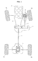
- FIG. 1 is a schematic plan view from above a four wheel drive vehicle, showing a powertrain of the four wheel drive vehicle which is provided with a roller-type friction transmission unit 1 according to a first embodiment of the present invention.
- the four wheel drive vehicle of FIG. 1 is based on a rear wheel drive vehicle in which rotation from an engine 2 is shifted by a transmission 3, and then transmitted through a rear propeller shaft 4 and a rear final drive unit 5 to left and right rear wheels 6L, 6R, and constructed so that a part of torque to left and right rear wheels (main driving wheels) 6L, 6R is transmitted by roller-type friction transmission unit 1 through a front propeller shaft 7 and a front final drive unit 8 to left and right front wheels (auxiliary driving wheels) 7L, 7R, thus achieving four wheel driving.
- Roller-type friction transmission unit 1 is thus configured to set a torque distribution ratio between left and right rear wheels (main driving wheels) 6L, 6R, and left and right front wheels (auxiliary driving wheels) 9L, 9R by splitting and outputting to left and right front wheels (auxiliary driving wheels) 7L, 7R a part of torque to left and right rear wheels (main driving wheels) 6L, 6R.
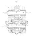
- roller-type friction transmission unit 1 is constructed as shown in FIG. 2 .
- an input shaft 12 and an output shaft 13 are arranged to extend laterally in a unit housing 11 so that a rotation axis O1 of input shaft 12 and a rotation axis 02 of output shaft 13 are parallel to each other.
- Input shaft 12 is rotatably supported at its both ends by bearings 14, 15 with respect to unit housing 11, for free rotation around axis 01.
- the both ends of input shaft 12 are made to project out from unit housing 11.
- the left end of input shaft 12 is connected to engine 2 through the transmission 3 (see FIG. 1 ), whereas the right end of input shaft 12 is connected to rear final drive unit 5 through the rear propeller shaft 4 (see FIG. 1 ).
- Output shaft 13 is rotatably supported at both ends with respect to unit housing 11 by a pivotal support structure as described below.
- An eccentric sleeve 16L and an eccentric sleeve 16R are loosely fitted between output shaft 13 and unit housing 11 through which respective ends of output shaft 13 extend, wherein eccentric sleeves 16L, 16R are configured to be fit.
- a bearing 17L is disposed between eccentric sleeve 16L and unit housing 11 so that eccentric sleeve 16L is rotatably supported through its outer peripheral surface 16Lb with respect to unit housing 11.
- a bearing 17R is disposed between eccentric sleeve 16R and unit housing 11 so that eccentric sleeve 16R is rotatably supported through its outer peripheral surface 17Rb with respect to unit housing 11.
- a bearing 18L is disposed between eccentric sleeve 16L and output shaft 13 so that output shaft 13 is rotatably supported through its outer peripheral surface within a hollow 16La of eccentric sleeve 16L.
- a bearing 18R is disposed between eccentric sleeve 16R and output shaft 13 so that output shaft 13 is rotatably supported through its outer peripheral surface within a hollow 16Ra of eccentric sleeve 16R. In this way, output shaft 13 can rotate freely around the axis 02 in hollows 16La, 16Ra of eccentric sleeves 16L, 16R.
- both ends of output shaft 13 are rotatably supported in unit housing 11 through the eccentric sleeves 16L, 16R.
- output shaft 13 thus supported in unit housing 11 the left end projecting out from unit housing 11 in FIG. 2 is connected to front propeller shaft 7 (see FIG. 1 ), so that the left end of output shaft 13 is connected to left and right front wheels 9L, 9R through the front propeller shaft 7 and front final drive unit 8.
- Input shaft 12 is coupled integrally or formed integrally with a first roller 21 arranged at a middle portion between both ends of input shaft 12, whereas output shaft 13 is coupled integrally or formed integrally with a second roller 22 arranged at a middle portion between both ends of output shaft 13.
- First roller 21 and second roller 22 are arranged in a plane perpendicular to the axial direction.
- the place between each axial end of first roller 21 and unit housing 11 is provided with a thrust bearing 23, wherein thrust bearing 23 serves to position in the axial direction the first roller 21 as well as input shaft 12.
- the outer peripheral surfaces 16Lb, 16Rb of eccentric sleeves 16L, 16R have a central axis O3 that is eccentric by ⁇ with respect to the central axis 02 of eccentric sleeve hollows 16La, 16Ra (radius Ri).
- eccentric sleeves 16L, 16R are rotated with respect to unit housing 11 around the rotation axis 03, the rotation axis 02 of output shaft 13 and second roller 22 rotates around the rotation axis O3. Accordingly, the radial pressing force from second roller 22 (outer peripheral surface 22a) to first roller 21 (outer peripheral surface 21a) varies and thereby allows the contact friction force (transmitted torque capacity) between first roller 21 and second roller 22 to be controlled.
- ring gears 16Lc, 16Rc are provided integrally with eccentric sleeves 16L, 16R, close to respective ones of the ends of eccentric sleeves 16L, 16R facing each other.
- These ring gears 16Lc, 16Rc are meshed with a common eccentric sleeve drive pinion not shown which is configured to be fit.
- the eccentric sleeve drive pinion is coupled to an inter-roller radial pressing force control motor not shown.
- the eccentric sleeve drive pinion is meshed with ring gears 16Lc, 16Rc by setting the eccentric sleeves 16L, 16R in such rotational positions that the eccentric outer peripheral surfaces 16Lb, 16Rb are aligned with each other in the circumferential direction, and then meshing the eccentric sleeve drive pinion with the ring gears 16Lc, 16Rc.
- a thrust bearing 24 is disposed between each ring gear 16Lc, 16Rc and unit housing 11.
- a thrust bearing 25 is disposed between second roller 22 and each eccentric sleeve 16L, 16R. These thrust bearings 24, 25 serve to position the eccentric sleeves 16L, 16R and second roller 22 (output shaft 13) in the axial direction.
- both of the outer peripheral surface 21a of first roller 21 and the outer peripheral surface 22a of second roller 22 in frictional contact with one another as described above are cylindrical surfaces, the roller outer peripheral surfaces 21a, 22a are in line contact with one another. Accordingly, if the parallelism between the rotation axis O1 and rotation axis 02 is lowered by errors in assembling or errors in precision of parts, it significantly adversely affects the endurance and transmission efficiency of the roller-type friction transmission unit, which is not robust.
- roller outer peripheral surfaces 21a, 22a are in frictional contact with each other at a single point may raise the contact pressure between the rollers at that contact point, and thereby cause the following problem.
- the traction coefficient ( ⁇ ) between rollers 21, 22 has a characteristic of change (namely, ⁇ -V characteristic) with respect to the slip speed between rollers 21, 22 (outer peripheral surfaces 21a, 22a) in frictional contact with each other, namely, with respect to inter-roller slip speed (V), for example, as indicated by a solid line in FIG. 5 , under influence of the kind of oil and operating condition (rotational speed, inter-roller radial pressing force, etc.).
- traction coefficient ( ⁇ ) rapidly rises to a maximum value immediately after the occurrence of inter-roller slip speed (V), and thereafter traction coefficient ( ⁇ ) gradually decreases from the maximum value as inter-roller slip speed (V) increases.
- the ideal slip speed (Vo1) that is inter-roller slip speed (V) when traction coefficient ( ⁇ ) reaches the maximum value ( ⁇ max1), and the maximum value ( ⁇ max) of traction coefficient ( ⁇ ), and the range of negative gradient in which traction coefficient ( ⁇ ) gradually decreases from the maximum value ( ⁇ max), and the descending gradient ( ⁇ 1) of traction coefficient ( ⁇ ) in the range of negative gradient, vary according to the contact pressure between the rollers at the spot of contact between the roller outer peripheral surfaces 21a, 22a.
- the present embodiment is based on recognition that this problem is caused by the high contact pressure between the rollers 21, 22 (outer peripheral surfaces 21a, 22a).
- the configuration of outer peripheral surfaces 21a, 22a of rollers 21, 22 are modified.
- the outer peripheral surface 22a of second roller 22 is formed as a cylindrical surface
- the outer peripheral surface 21a of first roller 21 is formed as a corrugated surface including a plurality (three in the case of FIG. 2 ) of convex surfaces 21b, 21c, 21d arranged in the axial direction, wherein each convex surface has a relatively raised portion middle in the axial direction.
- This allows the outer peripheral surface 21a of first roller 21 to be in contact with the outer peripheral surface 22a of second roller 22 at three spots ⁇ 1, ⁇ 2, ⁇ 3 arranged in the axial direction which spots correspond to the apexes of convex surfaces 21b, 21c, 21d respectively.
- roller-type friction transmission unit 1 directs from first roller 21 to output shaft 13 through the second roller 22 a part of torque to left and right rear wheels 6L, 6R.
- the torque transmitted to output shaft 13 is transmitted from the left end of output shaft 13 in FIG. 2 to left and right front wheels (auxiliary driving wheels) 7L, 7R through the front propeller shaft 7 (see FIG. 1 ) and front final drive unit 8.
- the vehicle is capable of performing four wheel drive running by driving all of left and right rear wheels (main driving wheels) 6L, 6R and left and right front wheels (auxiliary driving wheels) 7L, 7R.
- the control of driving force distribution between left and right rear wheels 6L, 6R and left and right front wheels 7L, 7R is implemented by rotating the eccentric sleeves 16L, 16R around the axis O3 through the ring gears 16Lc, 16Rc by the inter-roller radial pressing force control motor not shown but described above.
- eccentric sleeves 16L, 16R around the axis 03 causes the rotation axis O2 of output shaft 13 and second roller 22 to rotate around the axis 03, and allows the radial pressing force from second roller 22 to first roller 21, and thereby the transmitted torque capacity between rollers 21, 22 (driving force distribution between front wheel and rear wheel), to be arbitrarily controlled by changing the inter-axis distance between rollers 21, 22, and thereby allows driving force distribution control between left and right rear wheels 6L, 6R and left and right front wheels 7L, 7R.
- the roller-type friction transmission unit according to the first embodiment is configured so that the outer peripheral surface 22a of second roller 22 is formed as a cylindrical surface, but the outer peripheral surface 22a of first roller 21 is formed as a corrugated surface including a plurality (three in the case of FIG. 2 ) of convex surfaces 21b, 21c, 21d arranged in the axial direction, wherein each convex surface has a relatively raised portion middle in the axial direction, and this allows the outer peripheral surface 22a of first roller 21 to be in contact with the outer peripheral surface 22a of second roller 22 at three spots ⁇ 1, ⁇ 2, ⁇ 3 arranged in the axial direction which spots correspond to the apexes of convex surfaces 21b, 21c, 21d respectively.
- This serves to reduce the contact pressure between rollers 21, 22 (outer peripheral surfaces 21a, 22a) as compared to the conventional case, while maintaining the robustness, and thereby produce the following advantageous effects.
- the construction that the contact pressure between rollers 21, 22 (outer peripheral surfaces 21a, 22a) is thus low serves to set the ⁇ -V characteristic as indicated by a broken line from the solid line in FIG. 5 even when the condition is identical.
- (4) ideal slip speed (Vo) can be raised as high as (Vo2), thereby narrowing the range of negative gradient, and (5) the maximum value of traction coefficient ( ⁇ ) can be set as high as ( ⁇ max2), and (6) the descending gradient of traction coefficient ( ⁇ ) can be reduced as slow as ( ⁇ 2), to reduce the amount of fall of traction coefficient ( ⁇ ) in the range of negative gradient, in cooperation with the narrowing of the range of negative gradient.
- the roller-type friction transmission unit is capable of performing smooth power transmission between rollers 21, 22 even in the range of negative gradient in ⁇ -V characteristic indicated by the broken line in FIG. 5 , and thereby prevent judder (noise, vibration) from occurring between rollers 21, 22 (outer peripheral surfaces 21a, 22a) in the range of negative gradient.
- FIG. 3 shows a roller-type friction transmission unit according to a second embodiment of the present invention.
- the outer peripheral surface 21a of first roller 21 is formed as a single convex surface 21e including a relatively raised portion middle in the axial direction
- the outer peripheral surface 22a of second roller 22 is formed as a V-groove surface 22b, 22c including a relatively recessed portion middle in the axial direction.
- the outer peripheral surface 21a of first roller 21 formed as single convex surface 21e is in frictional contact with the V-groove surface 22b of second roller 22 constituting the outer peripheral surface 22a of second roller 22 at spot ⁇ 1
- the outer peripheral surface 21a of first roller 21 formed as single convex surface 21e is in frictional contact with the V-groove surface 22c of second roller 22 constituting the outer peripheral surface 22a of second roller 22 at spot ⁇ 2.
- the outer peripheral surface 21a of first roller 21 and the outer peripheral surface 22a of second roller 22 are in frictional contact with each other at spots ⁇ 1, ⁇ 2 arranged in the axial direction.
- the feature that the outer peripheral surface 21a of first roller 21 and the outer peripheral surface 22a of second roller 22 are in frictional contact with each other at spots ⁇ 1, ⁇ 2 arranged in the axial direction serves to reduce the contact pressure between rollers 21, 22 (outer peripheral surfaces 21a, 22a) as compared to the conventional configuration, while maintaining the robustness, and thereby produce similar advantageous effects as in the first embodiment.
- both of the outer peripheral surface 21a of first roller 21 and the outer peripheral surface 22a of second roller 22 have simpler shapes than the first roller outer peripheral surface 21a of the first embodiment shown in FIG. 2 , serves to suppress the processing cost, which is advantageous in view of cost.
- the outer peripheral surface 21a of first roller 21 formed as single convex surface 21e and the outer peripheral surface 22a of second roller 22 formed as V-groove surface 22b, 22c serve in cooperation to equalize the contact pressures at spots ⁇ 1, ⁇ 2 of contact between first roller 21 and second roller 22, and thereby prevent judder from occurring due to rise of one of the contact pressures. This serves to prevent judder with more reliability than in the first embodiment.
- FIG. 4 shows a roller-type friction transmission unit according to a third embodiment of the present invention.
- the outer peripheral surface 21a of first roller 21 is formed as a single convex surface 21e including a relatively raised portion middle in the axial direction as in the second embodiment shown in FIG. 3 .
- the outer peripheral surface 22a of second roller 22 is formed as a continuous concave surface including a relatively recessed portion middle in the axial direction, wherein the continuous concave surface is a combination of concave surfaces 22d, 22e configured to be in contact with the single convex surface 21e at two spots ⁇ 1, y2 arranged in the axial direction.
- the outer peripheral surface 21a of first roller 21 formed as single convex surface 21e is in frictional contact with the first concave surface 22d of second roller 22 constituting the outer peripheral surface 22a of second roller 22 at spot ⁇ 1
- the outer peripheral surface 21a of first roller 21 formed as single convex surface 21e is in frictional contact with the second concave surface 22e of second roller 22 constituting the outer peripheral surface 22a of second roller 22 at spot y2.
- the outer peripheral surface 21a of first roller 21 and the outer peripheral surface 22a of second roller 22 are in frictional contact with each other at spots ⁇ 1, y2 arranged in the axial direction.
- the feature that the outer peripheral surface 21a of first roller 21 and the outer peripheral surface 22a of second roller 22 are in frictional contact with each other at spots ⁇ 1, y2 arranged in the axial direction serves to reduce the contact pressure between rollers 21, 22 (outer peripheral surfaces 21a, 22a) as compared to the conventional configuration, while maintaining the robustness, and thereby produce similar advantageous effects as in the first and second embodiments.
- the contact area between the outer peripheral surface 21a of first roller 21 and the outer peripheral surface 22a of second roller 22 can be set larger than in the second embodiment, because the contact between the convex surface 21e and concave surface 22d, 22e at spot ⁇ 1, y2 is a contact between curved surfaces. Accordingly, the third embodiment makes it possible to set smaller the contact pressure between first roller 21 and second roller 22, to enhance the advantageous effects described above, than in the second embodiment.
- roller-type friction transmission unit 1 is configured to be capable of controlling the contact frictional force (transmitted torque capacity) between first roller 21 and second roller 22 by adjusting the radial pressing force from second roller 22 (outer peripheral surface 22a) to first roller 21 (outer peripheral surface 21a).
- the concept of the present invention described above can be applied also to a construction where the radial pressing force from second roller 22 (outer peripheral surface 22a) to first roller 21 (outer peripheral surface 21a) is fixed and incapable of being adjusted, and the contact frictional force (transmitted torque capacity) between first roller 21 and second roller 22 cannot be controlled.
- first roller outer peripheral surface 21a and the shape of the second roller outer peripheral surface 22a may be replaced with each other as different from the examples shown in the drawings. These modified examples produce similar advantageous effects.
Landscapes
- Engineering & Computer Science (AREA)
- General Engineering & Computer Science (AREA)
- Mechanical Engineering (AREA)
- Chemical & Material Sciences (AREA)
- Combustion & Propulsion (AREA)
- Transportation (AREA)
- Friction Gearing (AREA)
Abstract
Description
- The present invention relates to a roller-type friction transmission unit which is used as a transfer of a four wheel drive vehicle, and particularly relates to a technique for suppressing judder (noise, vibration) occurring between rollers in the roller-type friction transmission unit.
- Such a roller-type friction transmission unit is known as is described in a
patent document 1. The roller-type friction transmission unit described in this document includes a pair of rollers, wherein an outer peripheral surface of a first roller and an outer peripheral surface of a second roller are pressed in a radial direction of the first and second rollers into pressing contact with one another, to allow frictional power transmission between the first and second rollers; the first roller is connected to a driveline to main driving wheels of a four wheel drive vehicle; and the second roller is connected to a driveline to auxiliary driving wheels of the four wheel drive vehicle. - In the case of this roller-type friction transmission unit, if the outer peripheral surfaces of the rollers in contact with one another are cylindrical surfaces, the outer peripheral surfaces are in line contact with one another. Accordingly, if the parallelism between the roller rotation axes is lowered by errors in assembling or errors in precision of parts, it significantly adversely affects the endurance and transmission efficiency of the roller-type friction transmission unit. In this way, it is disadvantageous in view of robustness.
- Accordingly, in a typical roller-type friction transmission unit, the outer peripheral surface of one roller is formed to have a relatively raised portion middle in the axial direction, so that the outer peripheral surfaces of the rollers are in point contact with each other. In such a case, even if the parallelism between the roller rotation axes is lowered by errors in assembling or errors in precision of parts, the point contact between the outer peripheral surfaces of the rollers is maintained so that it does not significantly adversely affect the endurance and transmission efficiency of the roller-type friction transmission unit. In this way, it is superior in robustness.
- However, in the case of the conventional roller-type friction transmission unit described above, the configuration that roller outer peripheral surfaces are in frictional contact with each other at a single point may raise the contact pressure between the rollers at that contact point, and thereby cause the following problem.
- A roller-type friction transmission unit has a characteristic of change of traction coefficient (µ) with respect to inter-roller slip speed (V), which is so-called the µ-V characteristic, in which characteristic, traction coefficient (µ) rapidly rises to a maximum value immediately after the occurrence of inter-roller slip speed (V), and thereafter traction coefficient (µ) gradually decreases from the maximum value as inter-roller slip speed (V) increases.
- Although that tendency of µ-V characteristic is unchanged, the ideal slip speed (Vo) that is inter-roller slip speed (V) when traction coefficient (µ) reaches the maximum value, the maximum value (µmax) of traction coefficient (µ), the range of negative gradient in which traction coefficient (µ) gradually decreases from the maximum value (µmax), and the descending gradient (Δµ) of traction coefficient (µ), vary according to the contact pressure between the rollers at a spot of contact between the roller outer peripheral surfaces. Specifically, as the contact pressure between the rollers increases, (1) ideal slip speed (Vo) decreases to broaden the range of negative gradient, (2) the maximum value (µmax) of traction coefficient (µ) becomes small, and (3) the descending gradient (Δµ) of traction coefficient (µ) becomes rapid in addition to the broadening of the range of negative gradient, thereby increasing the amount of descending of traction coefficient (µ) in the range of negative gradient.
- In a conventional roller-type friction transmission unit, the feature that the roller outer peripheral surfaces are in contact with each other only at one point, and the inter-roller contact pressure at that point is high, results in that the µ-V characteristic has the tendencies (1)-(3) described above as indicated by a solid line in
FIG. 5 , so that smooth power transmission is difficult in the range of negative gradient of the µ-V characteristic, wherein judder (noise, vibration) tends to occur between the rollers. - Patent Document 1:
JP 2009-173261 A - It is an object of the present invention to provide a roller-type friction transmission unit that is configured to set the inter-roller contact pressure low and suppress judder from occurring between the rollers as described above, and thereby solve the problem described above.
- According to the present invention, in a roller-type friction transmission unit, an outer peripheral surface of a first roller and an outer peripheral surface of a second roller are pressed in a radial direction of the first and second rollers into pressing contact with one another, to allow frictional power transmission between the first and second rollers; one of the first and second rollers is connected to a driveline to main driving wheels of a four wheel drive vehicle; and another one of the first and second rollers is connected to a driveline to auxiliary driving wheels of the four wheel drive vehicle.
- In the present invention, the outer peripheral surface of the first roller and the outer peripheral surface of the second roller are shaped to allow the outer peripheral surface of the first roller and the outer peripheral surface of the second roller to be in contact with one another at a plurality of spots arranged in an axial direction of the first and second rollers.
- According to the roller-type friction transmission unit of the present invention, the feature that the outer peripheral surface of the first roller and the outer peripheral surface of the second roller are in contact with one another at a plurality of spots, serves to lower the inter-roller contact pressure at each contact spot.
- This results in narrowing the range of negative gradient and making mild the descending gradient of the traction coefficient in the range of negative gradient, and further increasing the maximum value of the traction coefficient, to allow smooth power transmission even in the range of negative gradient. This serves to suppress judder (noise, vibration) from occurring between the rollers in the range of negative gradient, and to solve the problem about judder described above.
-
-
FIG. 1 is a schematic plan view from above a four wheel drive vehicle, showing a powertrain of the four wheel drive vehicle which is provided with a roller-type friction transmission unit according to a first embodiment of the present invention. -
FIG. 2 is a side sectional view of the roller-type friction transmission unit ofFIG. 1 . -
FIG. 3 is a side sectional view similar toFIG. 2 , showing a roller-type friction transmission unit according to a second embodiment of the present invention. -
FIG. 4 is a side sectional view similar toFIG. 2 , showing a roller-type friction transmission unit according to a third embodiment of the present invention. -
FIG. 5 is a characteristic diagram showing a characteristic of change of traction coefficient with respect to inter-roller slip speed in the roller-type friction transmission unit according to the first embodiment shown inFIGS. 1 ,2 . - The following describes embodiments of the present invention in detail with reference to the drawings.
<Configuration of First Embodiment>FIG. 1 is a schematic plan view from above a four wheel drive vehicle, showing a powertrain of the four wheel drive vehicle which is provided with a roller-typefriction transmission unit 1 according to a first embodiment of the present invention. - The four wheel drive vehicle of
FIG. 1 is based on a rear wheel drive vehicle in which rotation from anengine 2 is shifted by atransmission 3, and then transmitted through arear propeller shaft 4 and a rear final drive unit 5 to left and rightrear wheels friction transmission unit 1 through afront propeller shaft 7 and a frontfinal drive unit 8 to left and right front wheels (auxiliary driving wheels) 7L, 7R, thus achieving four wheel driving. - Roller-type
friction transmission unit 1 is thus configured to set a torque distribution ratio between left and right rear wheels (main driving wheels) 6L, 6R, and left and right front wheels (auxiliary driving wheels) 9L, 9R by splitting and outputting to left and right front wheels (auxiliary driving wheels) 7L, 7R a part of torque to left and right rear wheels (main driving wheels) 6L, 6R. In this embodiment, roller-typefriction transmission unit 1 is constructed as shown inFIG. 2 . - In
FIG. 2 , aninput shaft 12 and anoutput shaft 13 are arranged to extend laterally in aunit housing 11 so that a rotation axis O1 ofinput shaft 12 and arotation axis 02 ofoutput shaft 13 are parallel to each other.Input shaft 12 is rotatably supported at its both ends bybearings unit housing 11, for free rotation aroundaxis 01. The both ends ofinput shaft 12 are made to project out fromunit housing 11. InFIG. 2 , the left end ofinput shaft 12 is connected toengine 2 through the transmission 3 (seeFIG. 1 ), whereas the right end ofinput shaft 12 is connected to rear final drive unit 5 through the rear propeller shaft 4 (seeFIG. 1 ). -
Output shaft 13 is rotatably supported at both ends with respect tounit housing 11 by a pivotal support structure as described below. Aneccentric sleeve 16L and aneccentric sleeve 16R, each of which is in the form of a hollow outer shaft, are loosely fitted betweenoutput shaft 13 andunit housing 11 through which respective ends ofoutput shaft 13 extend, whereineccentric sleeves - A
bearing 17L is disposed betweeneccentric sleeve 16L andunit housing 11 so thateccentric sleeve 16L is rotatably supported through its outer peripheral surface 16Lb with respect tounit housing 11. Abearing 17R is disposed betweeneccentric sleeve 16R andunit housing 11 so thateccentric sleeve 16R is rotatably supported through its outer peripheral surface 17Rb with respect tounit housing 11. - A
bearing 18L is disposed betweeneccentric sleeve 16L andoutput shaft 13 so thatoutput shaft 13 is rotatably supported through its outer peripheral surface within a hollow 16La ofeccentric sleeve 16L. Abearing 18R is disposed betweeneccentric sleeve 16R andoutput shaft 13 so thatoutput shaft 13 is rotatably supported through its outer peripheral surface within a hollow 16Ra ofeccentric sleeve 16R. In this way,output shaft 13 can rotate freely around theaxis 02 in hollows 16La, 16Ra ofeccentric sleeves - By the construction described above, both ends of
output shaft 13 are rotatably supported inunit housing 11 through theeccentric sleeves output shaft 13 thus supported inunit housing 11, the left end projecting out fromunit housing 11 inFIG. 2 is connected to front propeller shaft 7 (seeFIG. 1 ), so that the left end ofoutput shaft 13 is connected to left and rightfront wheels front propeller shaft 7 and frontfinal drive unit 8. -
Input shaft 12 is coupled integrally or formed integrally with afirst roller 21 arranged at a middle portion between both ends ofinput shaft 12, whereasoutput shaft 13 is coupled integrally or formed integrally with asecond roller 22 arranged at a middle portion between both ends ofoutput shaft 13.First roller 21 andsecond roller 22 are arranged in a plane perpendicular to the axial direction. The place between each axial end offirst roller 21 andunit housing 11 is provided with a thrust bearing 23, wherein thrust bearing 23 serves to position in the axial direction thefirst roller 21 as well asinput shaft 12. - The outer peripheral surfaces 16Lb, 16Rb of
eccentric sleeves central axis 02 of eccentric sleeve hollows 16La, 16Ra (radius Ri). In this construction, wheneccentric sleeves unit housing 11 around therotation axis 03, therotation axis 02 ofoutput shaft 13 andsecond roller 22 rotates around the rotation axis O3. Accordingly, the radial pressing force from second roller 22 (outerperipheral surface 22a) to first roller 21 (outerperipheral surface 21a) varies and thereby allows the contact friction force (transmitted torque capacity) betweenfirst roller 21 andsecond roller 22 to be controlled. - In order to allow control of the rotational position of
eccentric sleeves rotation axis 03, ring gears 16Lc, 16Rc are provided integrally witheccentric sleeves eccentric sleeves - The eccentric sleeve drive pinion is meshed with ring gears 16Lc, 16Rc by setting the
eccentric sleeves - A thrust bearing 24 is disposed between each ring gear 16Lc, 16Rc and
unit housing 11. A thrust bearing 25 is disposed betweensecond roller 22 and eacheccentric sleeve thrust bearings eccentric sleeves - If both of the outer
peripheral surface 21a offirst roller 21 and the outerperipheral surface 22a ofsecond roller 22 in frictional contact with one another as described above are cylindrical surfaces, the roller outerperipheral surfaces rotation axis 02 is lowered by errors in assembling or errors in precision of parts, it significantly adversely affects the endurance and transmission efficiency of the roller-type friction transmission unit, which is not robust. - On the other hand, in the case of the conventional roller-type friction transmission unit described above, the configuration that roller outer
peripheral surfaces - In the roller-type friction transmission unit where roller outer
peripheral surfaces rollers rollers 21, 22 (outerperipheral surfaces FIG. 5 , under influence of the kind of oil and operating condition (rotational speed, inter-roller radial pressing force, etc.). - The shape of this µ-V characteristic is constant with respect to variation of conditions. Specifically, traction coefficient (µ) rapidly rises to a maximum value immediately after the occurrence of inter-roller slip speed (V), and thereafter traction coefficient (µ) gradually decreases from the maximum value as inter-roller slip speed (V) increases.
- However, the ideal slip speed (Vo1) that is inter-roller slip speed (V) when traction coefficient (µ) reaches the maximum value (µmax1), and the maximum value (µmax) of traction coefficient (µ), and the range of negative gradient in which traction coefficient (µ) gradually decreases from the maximum value (µmax), and the descending gradient (Δµ1) of traction coefficient (µ) in the range of negative gradient, vary according to the contact pressure between the rollers at the spot of contact between the roller outer
peripheral surfaces peripheral surfaces - In a conventional roller-type friction transmission unit, the feature that the roller outer peripheral surfaces are in contact with each other only at one point, and the inter-roller contact pressure at that point is high, results in that the µ-V characteristic has the tendencies (1)-(3) described above as indicated by the solid line in
FIG. 5 , so that smooth power transmission is difficult in the range of negative gradient of the µ-V characteristic, wherein it is likely that judder (noise, vibration) occurs between the rollers21, 22 (outerperipheral surfaces - The present embodiment is based on recognition that this problem is caused by the high contact pressure between the
rollers 21, 22 (outerperipheral surfaces rollers 21, 22 (outerperipheral surfaces peripheral surfaces rollers - Specifically, as shown in
FIG. 2 , the outerperipheral surface 22a ofsecond roller 22 is formed as a cylindrical surface, while the outerperipheral surface 21a offirst roller 21 is formed as a corrugated surface including a plurality (three in the case ofFIG. 2 ) ofconvex surfaces peripheral surface 21a offirst roller 21 to be in contact with the outerperipheral surface 22a ofsecond roller 22 at three spots α1, α2, α3 arranged in the axial direction which spots correspond to the apexes ofconvex surfaces - <Operation of First Embodiment> The following describes operation of the roller-type friction transmission unit according to the first embodiment shown in
FIGS. 1 ,2 . The output torque oftransmission 3 inFIG. 1 is inputted intoinput shaft 12 from the left end inFIG. 2 . On one hand, the torque is transmitted directly frominput shaft 12 to left and right rear wheels (main driving wheels) 6L, 6R through therear propeller shaft 4 and rear final drive unit 5. - On the other hand, roller-type
friction transmission unit 1 directs fromfirst roller 21 tooutput shaft 13 through thesecond roller 22 a part of torque to left and rightrear wheels output shaft 13 is transmitted from the left end ofoutput shaft 13 inFIG. 2 to left and right front wheels (auxiliary driving wheels) 7L, 7R through the front propeller shaft 7 (seeFIG. 1 ) and frontfinal drive unit 8. - In this way, the vehicle is capable of performing four wheel drive running by driving all of left and right rear wheels (main driving wheels) 6L, 6R and left and right front wheels (auxiliary driving wheels) 7L, 7R. The control of driving force distribution between left and right
rear wheels eccentric sleeves - The rotation of
eccentric sleeves axis 03 causes the rotation axis O2 ofoutput shaft 13 andsecond roller 22 to rotate around theaxis 03, and allows the radial pressing force fromsecond roller 22 tofirst roller 21, and thereby the transmitted torque capacity betweenrollers 21, 22 (driving force distribution between front wheel and rear wheel), to be arbitrarily controlled by changing the inter-axis distance betweenrollers rear wheels - The roller-type friction transmission unit according to the first embodiment is configured so that the outer
peripheral surface 22a ofsecond roller 22 is formed as a cylindrical surface, but the outerperipheral surface 22a offirst roller 21 is formed as a corrugated surface including a plurality (three in the case ofFIG. 2 ) ofconvex surfaces peripheral surface 22a offirst roller 21 to be in contact with the outerperipheral surface 22a ofsecond roller 22 at three spots α1, α2, α3 arranged in the axial direction which spots correspond to the apexes ofconvex surfaces rollers 21, 22 (outerperipheral surfaces - The construction that the contact pressure between
rollers 21, 22 (outerperipheral surfaces FIG. 5 even when the condition is identical. Namely, (4) ideal slip speed (Vo) can be raised as high as (Vo2), thereby narrowing the range of negative gradient, and (5) the maximum value of traction coefficient (µ) can be set as high as (µmax2), and (6) the descending gradient of traction coefficient (µ) can be reduced as slow as (Δµ2), to reduce the amount of fall of traction coefficient (µ) in the range of negative gradient, in cooperation with the narrowing of the range of negative gradient. - Therefore, according to the first embodiment, the roller-type friction transmission unit is capable of performing smooth power transmission between
rollers FIG. 5 , and thereby prevent judder (noise, vibration) from occurring betweenrollers 21, 22 (outerperipheral surfaces - <Second Embodiment>
FIG. 3 shows a roller-type friction transmission unit according to a second embodiment of the present invention. In this embodiment, the outerperipheral surface 21a offirst roller 21 is formed as a singleconvex surface 21e including a relatively raised portion middle in the axial direction, and the outerperipheral surface 22a ofsecond roller 22 is formed as a V-groove surface - By this construction, the outer
peripheral surface 21a offirst roller 21 formed as singleconvex surface 21e is in frictional contact with the V-groove surface 22b ofsecond roller 22 constituting the outerperipheral surface 22a ofsecond roller 22 at spot β1, whereas the outerperipheral surface 21a offirst roller 21 formed as singleconvex surface 21e is in frictional contact with the V-groove surface 22c ofsecond roller 22 constituting the outerperipheral surface 22a ofsecond roller 22 at spot β2. Namely, the outerperipheral surface 21a offirst roller 21 and the outerperipheral surface 22a ofsecond roller 22 are in frictional contact with each other at spots β1, β2 arranged in the axial direction. - In the roller-type friction transmission unit according to the second embodiment, the feature that the outer
peripheral surface 21a offirst roller 21 and the outerperipheral surface 22a ofsecond roller 22 are in frictional contact with each other at spots β1, β2 arranged in the axial direction serves to reduce the contact pressure betweenrollers 21, 22 (outerperipheral surfaces - In addition, according to this embodiment, the feature that both of the outer
peripheral surface 21a offirst roller 21 and the outerperipheral surface 22a ofsecond roller 22 have simpler shapes than the first roller outerperipheral surface 21a of the first embodiment shown inFIG. 2 , serves to suppress the processing cost, which is advantageous in view of cost. - Moreover, according to this embodiment, the feature that the outer
peripheral surface 21a offirst roller 21 formed as singleconvex surface 21e and the outerperipheral surface 22a ofsecond roller 22 formed as V-groove surface first roller 21 andsecond roller 22, and thereby prevent judder from occurring due to rise of one of the contact pressures. This serves to prevent judder with more reliability than in the first embodiment. - <Third Embodiment>
FIG. 4 shows a roller-type friction transmission unit according to a third embodiment of the present invention. In this embodiment, the outerperipheral surface 21a offirst roller 21 is formed as a singleconvex surface 21e including a relatively raised portion middle in the axial direction as in the second embodiment shown inFIG. 3 . However, the outerperipheral surface 22a ofsecond roller 22 is formed as a continuous concave surface including a relatively recessed portion middle in the axial direction, wherein the continuous concave surface is a combination ofconcave surfaces convex surface 21e at two spots γ1, y2 arranged in the axial direction. - By this construction, the outer
peripheral surface 21a offirst roller 21 formed as singleconvex surface 21e is in frictional contact with the firstconcave surface 22d ofsecond roller 22 constituting the outerperipheral surface 22a ofsecond roller 22 at spot γ1, whereas the outerperipheral surface 21a offirst roller 21 formed as singleconvex surface 21e is in frictional contact with the secondconcave surface 22e ofsecond roller 22 constituting the outerperipheral surface 22a ofsecond roller 22 at spot y2. Namely, the outerperipheral surface 21a offirst roller 21 and the outerperipheral surface 22a ofsecond roller 22 are in frictional contact with each other at spots γ1, y2 arranged in the axial direction. - In the roller-type friction transmission unit according to the third embodiment, the feature that the outer
peripheral surface 21a offirst roller 21 and the outerperipheral surface 22a ofsecond roller 22 are in frictional contact with each other at spots γ1, y2 arranged in the axial direction serves to reduce the contact pressure betweenrollers 21, 22 (outerperipheral surfaces - Moreover, in the third embodiment, the contact area between the outer
peripheral surface 21a offirst roller 21 and the outerperipheral surface 22a ofsecond roller 22 can be set larger than in the second embodiment, because the contact between theconvex surface 21e andconcave surface first roller 21 andsecond roller 22, to enhance the advantageous effects described above, than in the second embodiment. - <Other Embodiments> In the embodiments described above, roller-type
friction transmission unit 1 is configured to be capable of controlling the contact frictional force (transmitted torque capacity) betweenfirst roller 21 andsecond roller 22 by adjusting the radial pressing force from second roller 22 (outerperipheral surface 22a) to first roller 21 (outerperipheral surface 21a). However, the concept of the present invention described above can be applied also to a construction where the radial pressing force from second roller 22 (outerperipheral surface 22a) to first roller 21 (outerperipheral surface 21a) is fixed and incapable of being adjusted, and the contact frictional force (transmitted torque capacity) betweenfirst roller 21 andsecond roller 22 cannot be controlled. - Moreover, in any of the embodiments, the shape of the first roller outer
peripheral surface 21a and the shape of the second roller outerperipheral surface 22a may be replaced with each other as different from the examples shown in the drawings. These modified examples produce similar advantageous effects.
Claims (4)
- A roller-type friction transmission unit, wherein:an outer peripheral surface of a first roller and an outer peripheral surface of a second roller are pressed in a radial direction of the first and second rollers into pressing contact with one another, to allow frictional power transmission between the first and second rollers;one of the first and second rollers is connected to a driveline to main driving wheels of a four wheel drive vehicle;another one of the first and second rollers is connected to a driveline to auxiliary driving wheels of the four wheel drive vehicle; andthe outer peripheral surface of the first roller and the outer peripheral surface of the second roller are shaped to allow the outer peripheral surface of the first roller and the outer peripheral surface of the second roller to be in contact with one another at a plurality of spots arranged in an axial direction of the first and second rollers.
- The roller-type friction transmission unit as claimed in Claim 1, wherein:one of the outer peripheral surface of the first roller and the outer peripheral surface of the second roller is formed as a cylindrical surface; andanother one of the outer peripheral surface of the first roller and the outer peripheral surface of the second roller is formed as a corrugated surface including a plurality of convex surfaces arranged in the axial direction, wherein each convex surface has a relatively raised portion middle in the axial direction.
- The roller-type friction transmission unit as claimed in Claim 1, wherein:one of the outer peripheral surface of the first roller and the outer peripheral surface of the second roller is formed as a single convex surface including a relatively raised portion middle in the axial direction;another one of the outer peripheral surface of the first roller and the outer peripheral surface of the second roller is formed as a V-groove surface including a relatively recessed portion middle in the axial direction; andthe outer peripheral surface of the first roller and the outer peripheral surface of the second roller are configured to be in contact with one another at two spots arranged in the axial direction.
- The roller-type friction transmission unit as claimed in Claim 1, wherein:one of the outer peripheral surface of the first roller and the outer peripheral surface of the second roller is formed as a single convex surface including a relatively raised portion middle in the axial direction; andanother one of the outer peripheral surface of the first roller and the outer peripheral surface of the second roller is formed as a continuous concave surface including a relatively recessed portion middle in the axial direction, wherein the continuous concave surface is a combination of concave surfaces configured to be in contact with the single convex surface at two spots arranged in the axial direction.
Applications Claiming Priority (2)
| Application Number | Priority Date | Filing Date | Title |
|---|---|---|---|
| JP2010258044A JP5817104B2 (en) | 2010-11-18 | 2010-11-18 | Roller friction transmission unit |
| PCT/JP2011/072017 WO2012066854A1 (en) | 2010-11-18 | 2011-09-27 | Roller-type friction transmission unit |
Publications (3)
| Publication Number | Publication Date |
|---|---|
| EP2641770A1 true EP2641770A1 (en) | 2013-09-25 |
| EP2641770A4 EP2641770A4 (en) | 2014-04-16 |
| EP2641770B1 EP2641770B1 (en) | 2015-08-12 |
Family
ID=46083797
Family Applications (1)
| Application Number | Title | Priority Date | Filing Date |
|---|---|---|---|
| EP11841101.6A Not-in-force EP2641770B1 (en) | 2010-11-18 | 2011-09-27 | Roller-type friction transmission unit |
Country Status (5)
| Country | Link |
|---|---|
| US (1) | US9200698B2 (en) |
| EP (1) | EP2641770B1 (en) |
| JP (1) | JP5817104B2 (en) |
| CN (1) | CN103201131A (en) |
| WO (1) | WO2012066854A1 (en) |
Families Citing this family (6)
| Publication number | Priority date | Publication date | Assignee | Title |
|---|---|---|---|---|
| WO2012086312A1 (en) * | 2010-12-24 | 2012-06-28 | 日産自動車株式会社 | Traction transmission capacity control device |
| WO2013183413A1 (en) * | 2012-06-05 | 2013-12-12 | 日産自動車株式会社 | Driving force distribution device |
| US20140013902A1 (en) * | 2012-07-10 | 2014-01-16 | Nissan Motor Co., Ltd. | Drive force distributing apparatus |
| JP2014019168A (en) * | 2012-07-12 | 2014-02-03 | Nissan Motor Co Ltd | Drive power distribution device |
| JP6413107B2 (en) * | 2012-12-10 | 2018-10-31 | 日産自動車株式会社 | Roller transmission device and driving force distribution device |
| US9718353B2 (en) * | 2015-09-01 | 2017-08-01 | Ronald Scott Bandy | Chassis for independent suspension system |
Family Cites Families (19)
| Publication number | Priority date | Publication date | Assignee | Title |
|---|---|---|---|---|
| US1709345A (en) * | 1927-07-07 | 1929-04-16 | Garrard Gears Ltd | Change-speed gear |
| US1910777A (en) * | 1931-02-19 | 1933-05-23 | Soddy Frederick | Epicyclic gearing |
| DE1202088B (en) * | 1963-05-07 | 1965-09-30 | Siemens Ag | Friction gears |
| US3848476A (en) * | 1973-06-05 | 1974-11-19 | Excelermatic | Traction roller transmission |
| US4051695A (en) * | 1976-04-27 | 1977-10-04 | Airco, Inc. | Rotating shaft coupling for use in vacuum |
| US4128016A (en) * | 1976-07-06 | 1978-12-05 | Nasvytis Algirdas L | Hybrid roller gear transmission |
| FR2502359B1 (en) * | 1981-03-23 | 1985-07-05 | Renault | MANUAL CONTROL SYSTEM FOR AN ELECTRICAL DEVICE |
| JPS57184351A (en) | 1981-05-08 | 1982-11-13 | Fujitsu General Ltd | Method and device for collection of data |
| JPS57184351U (en) * | 1981-05-18 | 1982-11-22 | ||
| JP2002087092A (en) * | 2000-09-20 | 2002-03-26 | Tochigi Fuji Ind Co Ltd | Power transmission device |
| US6849025B2 (en) * | 2001-04-09 | 2005-02-01 | Nsk Ltd. | Frictional roller transmission |
| DE10315682A1 (en) * | 2003-04-07 | 2004-11-11 | Zf Friedrichshafen Ag | All-wheel toroidal transmission for a motor vehicle |
| JP4821208B2 (en) * | 2005-08-08 | 2011-11-24 | 日産自動車株式会社 | Vehicle driving force distribution device |
| JP5262588B2 (en) * | 2007-12-26 | 2013-08-14 | 日産自動車株式会社 | Driving force distribution device |
| US8402851B2 (en) * | 2008-01-24 | 2013-03-26 | Nissan Motor Co., Ltd. | Friction-roller type transmission mechanism |
| JP5195511B2 (en) * | 2009-02-25 | 2013-05-08 | 日産自動車株式会社 | Driving force distribution device |
| JP5326676B2 (en) * | 2009-03-07 | 2013-10-30 | 日産自動車株式会社 | Friction transmission |
| JP5131384B2 (en) * | 2009-06-03 | 2013-01-30 | 日産自動車株式会社 | Two-wheel / four-wheel drive switching control device and control method for traction transmission type part-time four-wheel drive vehicle |
| JP5644455B2 (en) * | 2010-12-09 | 2014-12-24 | 日産自動車株式会社 | Roller friction transmission unit |
-
2010
- 2010-11-18 JP JP2010258044A patent/JP5817104B2/en not_active Expired - Fee Related
-
2011
- 2011-09-27 EP EP11841101.6A patent/EP2641770B1/en not_active Not-in-force
- 2011-09-27 WO PCT/JP2011/072017 patent/WO2012066854A1/en not_active Ceased
- 2011-09-27 CN CN2011800539702A patent/CN103201131A/en active Pending
- 2011-09-27 US US13/818,528 patent/US9200698B2/en not_active Expired - Fee Related
Also Published As
| Publication number | Publication date |
|---|---|
| EP2641770A4 (en) | 2014-04-16 |
| US9200698B2 (en) | 2015-12-01 |
| EP2641770B1 (en) | 2015-08-12 |
| JP2012107721A (en) | 2012-06-07 |
| WO2012066854A1 (en) | 2012-05-24 |
| JP5817104B2 (en) | 2015-11-18 |
| US20130157803A1 (en) | 2013-06-20 |
| CN103201131A (en) | 2013-07-10 |
Similar Documents
| Publication | Publication Date | Title |
|---|---|---|
| EP2641770B1 (en) | Roller-type friction transmission unit | |
| KR102367587B1 (en) | Compound planetary friction drive | |
| WO2004070233A1 (en) | Traction drive type continuously variable transmission | |
| CN102123881A (en) | Final drive for a work machine | |
| US8187134B2 (en) | Friction roller type power transmission device | |
| CN113574294B (en) | Friction roller reducer | |
| JP5644455B2 (en) | Roller friction transmission unit | |
| JP6326252B2 (en) | Reduction gear bearing preload mechanism | |
| WO2019021555A1 (en) | Differential for motor vehicle and transmission for motor vehicle | |
| CN101283201B (en) | Planetary roller transmission device and vehicle equipped with the device | |
| CN102272478B (en) | Drive force distribution device | |
| JP2007057040A (en) | Continuously variable transmission device | |
| JP2004263857A (en) | Traction drive type continuously variable transmission | |
| CN106574698A (en) | Stepless transmission | |
| JP2009057993A (en) | Continuously variable transmission | |
| CN102252075A (en) | Friction pair planet driven continuously variable transmission | |
| JP2014214838A (en) | Continuously variable transmission | |
| JP2009052666A (en) | Planetary roller device | |
| JP2009036237A (en) | Continuously variable transmission | |
| CN101110537B (en) | Transmission system with unidirectional gear and rim motor with the transmission system | |
| JP2009047218A (en) | Continuously variable transmission | |
| JP2014040892A (en) | Frictional roller type transmission | |
| JP6311452B2 (en) | Toroidal continuously variable transmission | |
| JP2005214373A (en) | Toroidal continuously variable transmission | |
| JP4519707B2 (en) | Traction drive continuously variable transmission |
Legal Events
| Date | Code | Title | Description |
|---|---|---|---|
| PUAI | Public reference made under article 153(3) epc to a published international application that has entered the european phase |
Free format text: ORIGINAL CODE: 0009012 |
|
| 17P | Request for examination filed |
Effective date: 20130320 |
|
| AK | Designated contracting states |
Kind code of ref document: A1 Designated state(s): AL AT BE BG CH CY CZ DE DK EE ES FI FR GB GR HR HU IE IS IT LI LT LU LV MC MK MT NL NO PL PT RO RS SE SI SK SM TR |
|
| DAX | Request for extension of the european patent (deleted) | ||
| A4 | Supplementary search report drawn up and despatched |
Effective date: 20140319 |
|
| RIC1 | Information provided on ipc code assigned before grant |
Ipc: F16H 13/04 20060101ALI20140313BHEP Ipc: B60K 17/344 20060101ALI20140313BHEP Ipc: B60K 17/348 20060101AFI20140313BHEP |
|
| GRAP | Despatch of communication of intention to grant a patent |
Free format text: ORIGINAL CODE: EPIDOSNIGR1 |
|
| INTG | Intention to grant announced |
Effective date: 20150512 |
|
| GRAS | Grant fee paid |
Free format text: ORIGINAL CODE: EPIDOSNIGR3 |
|
| GRAA | (expected) grant |
Free format text: ORIGINAL CODE: 0009210 |
|
| REG | Reference to a national code |
Ref country code: FR Ref legal event code: PLFP Year of fee payment: 5 |
|
| AK | Designated contracting states |
Kind code of ref document: B1 Designated state(s): AL AT BE BG CH CY CZ DE DK EE ES FI FR GB GR HR HU IE IS IT LI LT LU LV MC MK MT NL NO PL PT RO RS SE SI SK SM TR |
|
| REG | Reference to a national code |
Ref country code: GB Ref legal event code: FG4D |
|
| REG | Reference to a national code |
Ref country code: CH Ref legal event code: EP |
|
| REG | Reference to a national code |
Ref country code: AT Ref legal event code: REF Ref document number: 741809 Country of ref document: AT Kind code of ref document: T Effective date: 20150815 |
|
| REG | Reference to a national code |
Ref country code: IE Ref legal event code: FG4D |
|
| REG | Reference to a national code |
Ref country code: DE Ref legal event code: R096 Ref document number: 602011018818 Country of ref document: DE |
|
| PGFP | Annual fee paid to national office [announced via postgrant information from national office to epo] |
Ref country code: DE Payment date: 20150922 Year of fee payment: 5 Ref country code: GB Payment date: 20150923 Year of fee payment: 5 |
|
| PGFP | Annual fee paid to national office [announced via postgrant information from national office to epo] |
Ref country code: FR Payment date: 20150811 Year of fee payment: 5 |
|
| REG | Reference to a national code |
Ref country code: LT Ref legal event code: MG4D |
|
| REG | Reference to a national code |
Ref country code: AT Ref legal event code: MK05 Ref document number: 741809 Country of ref document: AT Kind code of ref document: T Effective date: 20150812 |
|
| REG | Reference to a national code |
Ref country code: NL Ref legal event code: MP Effective date: 20150812 |
|
| PG25 | Lapsed in a contracting state [announced via postgrant information from national office to epo] |
Ref country code: NO Free format text: LAPSE BECAUSE OF FAILURE TO SUBMIT A TRANSLATION OF THE DESCRIPTION OR TO PAY THE FEE WITHIN THE PRESCRIBED TIME-LIMIT Effective date: 20151112 Ref country code: GR Free format text: LAPSE BECAUSE OF FAILURE TO SUBMIT A TRANSLATION OF THE DESCRIPTION OR TO PAY THE FEE WITHIN THE PRESCRIBED TIME-LIMIT Effective date: 20151113 Ref country code: LV Free format text: LAPSE BECAUSE OF FAILURE TO SUBMIT A TRANSLATION OF THE DESCRIPTION OR TO PAY THE FEE WITHIN THE PRESCRIBED TIME-LIMIT Effective date: 20150812 Ref country code: FI Free format text: LAPSE BECAUSE OF FAILURE TO SUBMIT A TRANSLATION OF THE DESCRIPTION OR TO PAY THE FEE WITHIN THE PRESCRIBED TIME-LIMIT Effective date: 20150812 Ref country code: LT Free format text: LAPSE BECAUSE OF FAILURE TO SUBMIT A TRANSLATION OF THE DESCRIPTION OR TO PAY THE FEE WITHIN THE PRESCRIBED TIME-LIMIT Effective date: 20150812 |
|
| PG25 | Lapsed in a contracting state [announced via postgrant information from national office to epo] |
Ref country code: PT Free format text: LAPSE BECAUSE OF FAILURE TO SUBMIT A TRANSLATION OF THE DESCRIPTION OR TO PAY THE FEE WITHIN THE PRESCRIBED TIME-LIMIT Effective date: 20151214 Ref country code: PL Free format text: LAPSE BECAUSE OF FAILURE TO SUBMIT A TRANSLATION OF THE DESCRIPTION OR TO PAY THE FEE WITHIN THE PRESCRIBED TIME-LIMIT Effective date: 20150812 Ref country code: SE Free format text: LAPSE BECAUSE OF FAILURE TO SUBMIT A TRANSLATION OF THE DESCRIPTION OR TO PAY THE FEE WITHIN THE PRESCRIBED TIME-LIMIT Effective date: 20150812 Ref country code: HR Free format text: LAPSE BECAUSE OF FAILURE TO SUBMIT A TRANSLATION OF THE DESCRIPTION OR TO PAY THE FEE WITHIN THE PRESCRIBED TIME-LIMIT Effective date: 20150812 Ref country code: IS Free format text: LAPSE BECAUSE OF FAILURE TO SUBMIT A TRANSLATION OF THE DESCRIPTION OR TO PAY THE FEE WITHIN THE PRESCRIBED TIME-LIMIT Effective date: 20151212 Ref country code: ES Free format text: LAPSE BECAUSE OF FAILURE TO SUBMIT A TRANSLATION OF THE DESCRIPTION OR TO PAY THE FEE WITHIN THE PRESCRIBED TIME-LIMIT Effective date: 20150812 Ref country code: RS Free format text: LAPSE BECAUSE OF FAILURE TO SUBMIT A TRANSLATION OF THE DESCRIPTION OR TO PAY THE FEE WITHIN THE PRESCRIBED TIME-LIMIT Effective date: 20150812 Ref country code: AT Free format text: LAPSE BECAUSE OF FAILURE TO SUBMIT A TRANSLATION OF THE DESCRIPTION OR TO PAY THE FEE WITHIN THE PRESCRIBED TIME-LIMIT Effective date: 20150812 |
|
| PG25 | Lapsed in a contracting state [announced via postgrant information from national office to epo] |
Ref country code: NL Free format text: LAPSE BECAUSE OF FAILURE TO SUBMIT A TRANSLATION OF THE DESCRIPTION OR TO PAY THE FEE WITHIN THE PRESCRIBED TIME-LIMIT Effective date: 20150812 |
|
| PG25 | Lapsed in a contracting state [announced via postgrant information from national office to epo] |
Ref country code: DK Free format text: LAPSE BECAUSE OF FAILURE TO SUBMIT A TRANSLATION OF THE DESCRIPTION OR TO PAY THE FEE WITHIN THE PRESCRIBED TIME-LIMIT Effective date: 20150812 Ref country code: EE Free format text: LAPSE BECAUSE OF FAILURE TO SUBMIT A TRANSLATION OF THE DESCRIPTION OR TO PAY THE FEE WITHIN THE PRESCRIBED TIME-LIMIT Effective date: 20150812 Ref country code: CZ Free format text: LAPSE BECAUSE OF FAILURE TO SUBMIT A TRANSLATION OF THE DESCRIPTION OR TO PAY THE FEE WITHIN THE PRESCRIBED TIME-LIMIT Effective date: 20150812 Ref country code: SK Free format text: LAPSE BECAUSE OF FAILURE TO SUBMIT A TRANSLATION OF THE DESCRIPTION OR TO PAY THE FEE WITHIN THE PRESCRIBED TIME-LIMIT Effective date: 20150812 Ref country code: IT Free format text: LAPSE BECAUSE OF FAILURE TO SUBMIT A TRANSLATION OF THE DESCRIPTION OR TO PAY THE FEE WITHIN THE PRESCRIBED TIME-LIMIT Effective date: 20150812 |
|
| REG | Reference to a national code |
Ref country code: CH Ref legal event code: PL |
|
| REG | Reference to a national code |
Ref country code: DE Ref legal event code: R097 Ref document number: 602011018818 Country of ref document: DE |
|
| PG25 | Lapsed in a contracting state [announced via postgrant information from national office to epo] |
Ref country code: MC Free format text: LAPSE BECAUSE OF FAILURE TO SUBMIT A TRANSLATION OF THE DESCRIPTION OR TO PAY THE FEE WITHIN THE PRESCRIBED TIME-LIMIT Effective date: 20150812 Ref country code: RO Free format text: LAPSE BECAUSE OF FAILURE TO SUBMIT A TRANSLATION OF THE DESCRIPTION OR TO PAY THE FEE WITHIN THE PRESCRIBED TIME-LIMIT Effective date: 20150812 |
|
| PLBE | No opposition filed within time limit |
Free format text: ORIGINAL CODE: 0009261 |
|
| STAA | Information on the status of an ep patent application or granted ep patent |
Free format text: STATUS: NO OPPOSITION FILED WITHIN TIME LIMIT |
|
| REG | Reference to a national code |
Ref country code: IE Ref legal event code: MM4A |
|
| 26N | No opposition filed |
Effective date: 20160513 |
|
| PG25 | Lapsed in a contracting state [announced via postgrant information from national office to epo] |
Ref country code: IE Free format text: LAPSE BECAUSE OF NON-PAYMENT OF DUE FEES Effective date: 20150927 Ref country code: LI Free format text: LAPSE BECAUSE OF NON-PAYMENT OF DUE FEES Effective date: 20150930 Ref country code: CH Free format text: LAPSE BECAUSE OF NON-PAYMENT OF DUE FEES Effective date: 20150930 |
|
| PG25 | Lapsed in a contracting state [announced via postgrant information from national office to epo] |
Ref country code: SI Free format text: LAPSE BECAUSE OF FAILURE TO SUBMIT A TRANSLATION OF THE DESCRIPTION OR TO PAY THE FEE WITHIN THE PRESCRIBED TIME-LIMIT Effective date: 20150812 |
|
| PG25 | Lapsed in a contracting state [announced via postgrant information from national office to epo] |
Ref country code: BE Free format text: LAPSE BECAUSE OF FAILURE TO SUBMIT A TRANSLATION OF THE DESCRIPTION OR TO PAY THE FEE WITHIN THE PRESCRIBED TIME-LIMIT Effective date: 20150812 |
|
| PG25 | Lapsed in a contracting state [announced via postgrant information from national office to epo] |
Ref country code: MT Free format text: LAPSE BECAUSE OF FAILURE TO SUBMIT A TRANSLATION OF THE DESCRIPTION OR TO PAY THE FEE WITHIN THE PRESCRIBED TIME-LIMIT Effective date: 20150812 |
|
| REG | Reference to a national code |
Ref country code: DE Ref legal event code: R119 Ref document number: 602011018818 Country of ref document: DE |
|
| GBPC | Gb: european patent ceased through non-payment of renewal fee |
Effective date: 20160927 |
|
| PG25 | Lapsed in a contracting state [announced via postgrant information from national office to epo] |
Ref country code: BG Free format text: LAPSE BECAUSE OF FAILURE TO SUBMIT A TRANSLATION OF THE DESCRIPTION OR TO PAY THE FEE WITHIN THE PRESCRIBED TIME-LIMIT Effective date: 20150812 Ref country code: SM Free format text: LAPSE BECAUSE OF FAILURE TO SUBMIT A TRANSLATION OF THE DESCRIPTION OR TO PAY THE FEE WITHIN THE PRESCRIBED TIME-LIMIT Effective date: 20150812 Ref country code: HU Free format text: LAPSE BECAUSE OF FAILURE TO SUBMIT A TRANSLATION OF THE DESCRIPTION OR TO PAY THE FEE WITHIN THE PRESCRIBED TIME-LIMIT; INVALID AB INITIO Effective date: 20110927 |
|
| PG25 | Lapsed in a contracting state [announced via postgrant information from national office to epo] |
Ref country code: CY Free format text: LAPSE BECAUSE OF FAILURE TO SUBMIT A TRANSLATION OF THE DESCRIPTION OR TO PAY THE FEE WITHIN THE PRESCRIBED TIME-LIMIT Effective date: 20150812 |
|
| REG | Reference to a national code |
Ref country code: FR Ref legal event code: ST Effective date: 20170531 |
|
| PG25 | Lapsed in a contracting state [announced via postgrant information from national office to epo] |
Ref country code: FR Free format text: LAPSE BECAUSE OF NON-PAYMENT OF DUE FEES Effective date: 20160930 Ref country code: DE Free format text: LAPSE BECAUSE OF NON-PAYMENT OF DUE FEES Effective date: 20170401 Ref country code: GB Free format text: LAPSE BECAUSE OF NON-PAYMENT OF DUE FEES Effective date: 20160927 |
|
| PG25 | Lapsed in a contracting state [announced via postgrant information from national office to epo] |
Ref country code: LU Free format text: LAPSE BECAUSE OF NON-PAYMENT OF DUE FEES Effective date: 20150927 |
|
| PG25 | Lapsed in a contracting state [announced via postgrant information from national office to epo] |
Ref country code: TR Free format text: LAPSE BECAUSE OF FAILURE TO SUBMIT A TRANSLATION OF THE DESCRIPTION OR TO PAY THE FEE WITHIN THE PRESCRIBED TIME-LIMIT Effective date: 20150812 Ref country code: MK Free format text: LAPSE BECAUSE OF FAILURE TO SUBMIT A TRANSLATION OF THE DESCRIPTION OR TO PAY THE FEE WITHIN THE PRESCRIBED TIME-LIMIT Effective date: 20150812 |
|
| PG25 | Lapsed in a contracting state [announced via postgrant information from national office to epo] |
Ref country code: AL Free format text: LAPSE BECAUSE OF FAILURE TO SUBMIT A TRANSLATION OF THE DESCRIPTION OR TO PAY THE FEE WITHIN THE PRESCRIBED TIME-LIMIT Effective date: 20150812 |