EP2641677A1 - Cutting insert - Google Patents
Cutting insert Download PDFInfo
- Publication number
- EP2641677A1 EP2641677A1 EP11840956.4A EP11840956A EP2641677A1 EP 2641677 A1 EP2641677 A1 EP 2641677A1 EP 11840956 A EP11840956 A EP 11840956A EP 2641677 A1 EP2641677 A1 EP 2641677A1
- Authority
- EP
- European Patent Office
- Prior art keywords
- region
- cutting edge
- cutting
- rake
- rake face
- Prior art date
- Legal status (The legal status is an assumption and is not a legal conclusion. Google has not performed a legal analysis and makes no representation as to the accuracy of the status listed.)
- Withdrawn
Links
Images


Classifications
-
- B—PERFORMING OPERATIONS; TRANSPORTING
- B23—MACHINE TOOLS; METAL-WORKING NOT OTHERWISE PROVIDED FOR
- B23B—TURNING; BORING
- B23B27/00—Tools for turning or boring machines; Tools of a similar kind in general; Accessories therefor
- B23B27/14—Cutting tools of which the bits or tips or cutting inserts are of special material
- B23B27/16—Cutting tools of which the bits or tips or cutting inserts are of special material with exchangeable cutting bits or cutting inserts, e.g. able to be clamped
- B23B27/1603—Cutting tools of which the bits or tips or cutting inserts are of special material with exchangeable cutting bits or cutting inserts, e.g. able to be clamped with specially shaped plate-like exchangeable cutting inserts, e.g. chip-breaking groove
- B23B27/1607—Cutting tools of which the bits or tips or cutting inserts are of special material with exchangeable cutting bits or cutting inserts, e.g. able to be clamped with specially shaped plate-like exchangeable cutting inserts, e.g. chip-breaking groove characterised by having chip-breakers
-
- B—PERFORMING OPERATIONS; TRANSPORTING
- B23—MACHINE TOOLS; METAL-WORKING NOT OTHERWISE PROVIDED FOR
- B23B—TURNING; BORING
- B23B27/00—Tools for turning or boring machines; Tools of a similar kind in general; Accessories therefor
-
- B—PERFORMING OPERATIONS; TRANSPORTING
- B23—MACHINE TOOLS; METAL-WORKING NOT OTHERWISE PROVIDED FOR
- B23B—TURNING; BORING
- B23B27/00—Tools for turning or boring machines; Tools of a similar kind in general; Accessories therefor
- B23B27/14—Cutting tools of which the bits or tips or cutting inserts are of special material
- B23B27/141—Specially shaped plate-like cutting inserts, i.e. length greater or equal to width, width greater than or equal to thickness
-
- B—PERFORMING OPERATIONS; TRANSPORTING
- B23—MACHINE TOOLS; METAL-WORKING NOT OTHERWISE PROVIDED FOR
- B23B—TURNING; BORING
- B23B2200/00—Details of cutting inserts
- B23B2200/04—Overall shape
- B23B2200/0447—Parallelogram
-
- B—PERFORMING OPERATIONS; TRANSPORTING
- B23—MACHINE TOOLS; METAL-WORKING NOT OTHERWISE PROVIDED FOR
- B23B—TURNING; BORING
- B23B2200/00—Details of cutting inserts
- B23B2200/04—Overall shape
- B23B2200/0447—Parallelogram
- B23B2200/0452—Parallelogram rounded
-
- B—PERFORMING OPERATIONS; TRANSPORTING
- B23—MACHINE TOOLS; METAL-WORKING NOT OTHERWISE PROVIDED FOR
- B23B—TURNING; BORING
- B23B2200/00—Details of cutting inserts
- B23B2200/08—Rake or top surfaces
- B23B2200/081—Rake or top surfaces with projections
-
- B—PERFORMING OPERATIONS; TRANSPORTING
- B23—MACHINE TOOLS; METAL-WORKING NOT OTHERWISE PROVIDED FOR
- B23B—TURNING; BORING
- B23B2200/00—Details of cutting inserts
- B23B2200/08—Rake or top surfaces
- B23B2200/085—Rake or top surfaces discontinuous
-
- B—PERFORMING OPERATIONS; TRANSPORTING
- B23—MACHINE TOOLS; METAL-WORKING NOT OTHERWISE PROVIDED FOR
- B23B—TURNING; BORING
- B23B2200/00—Details of cutting inserts
- B23B2200/20—Top or side views of the cutting edge
- B23B2200/201—Details of the nose radius and immediately surrounding area
-
- B—PERFORMING OPERATIONS; TRANSPORTING
- B23—MACHINE TOOLS; METAL-WORKING NOT OTHERWISE PROVIDED FOR
- B23B—TURNING; BORING
- B23B2200/00—Details of cutting inserts
- B23B2200/20—Top or side views of the cutting edge
- B23B2200/202—Top or side views of the cutting edge with curved cutting edge
-
- B—PERFORMING OPERATIONS; TRANSPORTING
- B23—MACHINE TOOLS; METAL-WORKING NOT OTHERWISE PROVIDED FOR
- B23B—TURNING; BORING
- B23B2200/00—Details of cutting inserts
- B23B2200/24—Cross section of the cutting edge
- B23B2200/242—Cross section of the cutting edge bevelled or chamfered
-
- B—PERFORMING OPERATIONS; TRANSPORTING
- B23—MACHINE TOOLS; METAL-WORKING NOT OTHERWISE PROVIDED FOR
- B23B—TURNING; BORING
- B23B2200/00—Details of cutting inserts
- B23B2200/28—Angles
- B23B2200/286—Positive cutting angles
-
- Y—GENERAL TAGGING OF NEW TECHNOLOGICAL DEVELOPMENTS; GENERAL TAGGING OF CROSS-SECTIONAL TECHNOLOGIES SPANNING OVER SEVERAL SECTIONS OF THE IPC; TECHNICAL SUBJECTS COVERED BY FORMER USPC CROSS-REFERENCE ART COLLECTIONS [XRACs] AND DIGESTS
- Y10—TECHNICAL SUBJECTS COVERED BY FORMER USPC
- Y10T—TECHNICAL SUBJECTS COVERED BY FORMER US CLASSIFICATION
- Y10T407/00—Cutters, for shaping
- Y10T407/23—Cutters, for shaping including tool having plural alternatively usable cutting edges
- Y10T407/235—Cutters, for shaping including tool having plural alternatively usable cutting edges with integral chip breaker, guide or deflector
Definitions
- the present invention relates to a cutting insert which is appropriately used in light cutting for turning a difficult-to-cut material such as stainless steel.
- Patent Document 1 has described such a problem that burrs will occur easily upon cutting these difficult-to-cut materials such as stainless steel, these burrs undergo work hardening to result in extremely low machinability and, therefore, a cutting edge of a cutting boundary which is exposed to the burrs is increased in chipping to fracture the cutting edge or greatly decrease the tool life due to what is called abnormal wear.
- Patent Document 1 proposes a cutting insert in which a cutting edge is formed substantially linearly at an inclination angle which is greater than 0° but smaller than 20° so that a distance of the cutting edge from a bottom face of a flat insert main body is small at a corner section and gradually increases as moving toward the center of the cutting edge, a breaker rake face of a chip breaker on an upper face is set at an angle of 20 to 30° and there is formed at an inner part of the breaker rake face a breaker wall which rises in a direction at which the height of the bottom face is gradually increased from a bottom of the chip breaker toward the inner part thereof, by which an upper face part inside the chip breaker is made lower than a peripheral cutting edge section.
- the cutting insert it is possible to reduce the occurrence of burrs even where the cutting edge is increased in inclination angle to cut a difficult-to-cut material such as stainless steel. Further, abnormal wear can be suppressed as much as possible to extend the tool life. Furthermore, what is called tenacious chips coming from a difficult-to-cut material can be broken into pieces reliably by the breaker wall of the chip breaker. Still further, even where the chips move along the breaker wall, resistance associated with the movement thereof can be reduced to prevent heating.
- Patent Document 2 proposes a cutting insert which is used appropriately in cutting stainless steel, that is, a breaker flute is formed to have a cross section which is constituted with a land (rake angle ⁇ 1), a first inclination face (rake angle 02), a second inclination face (rake angle 03) and a steep face, each of which has a positive rake angle sequentially from a cutting edge to a center so as to give the relationship of ⁇ 2> ⁇ 1> ⁇ 3>0, and the rake angle 01 of the land is increased at the corner but decreased at the center of a major cutting edge, while the width of the land is decreased at the corner but increased at the center of the major cutting edge.
- Patent Document 2 since the contact area between the breaker flute and the chips is small, the thus constituted cutting insert can suppress cutting resistance. Further, since a position of the cutting edge corresponding to the depth of cut where fracturing will take place easily is strengthened, the position is to be high in fracturing resistance.
- Patent Document 2 describes that the above-described result has been obtained in particular when the thus constituted cutting insert is used to perform light cutting of stainless steel (SUS304) under conditions that the cutting speed is 100 m/min, the depth of cut is 1 mm and the feed rate is 0.2 mm/rev.
- SUS304 stainless steel
- the present invention has been made in view of the above situation, an object of which is to provide a cutting insert which is capable of suppressing an undue decrease in the strength of a cutting edge on light cutting of a difficult-to-cut material such as stainless steel to ensure fracturing resistance and chipping resistance and also capable of suppressing the occurrence of burrs at a cutting boundary, thereby preventing abnormal wear.
- the cutting insert of the present invention is provided with an insert main body having a rake face and a flank face and a cutting edge formed at a ridge section between the rake face and the flank face in the insert main body.
- the cutting edge is provided with a corner section which forms a convex arc shape when seen in a planar view from a direction facing the rake face and a linear section which is in contact with the corner section at least at one end of the corner section and extends linearly.
- the cutting edge is provided with a first region along the corner section when seen in the planar view, a second region along the linear section and a third region positioned between the first region and the second region.
- a rake angle of the cutting edge in the third region is greater than rake angles of the cutting edges in the first region and the second region.
- the third region of the cutting edge is disposed at a cutting boundary when light cutting is performed by a turning process.
- the cutting edge is increased in sharpness at the cutting boundary to suppress the occurrence of burrs, thus making it possible to prevent progress of abnormal wear due to the burrs.
- the cutting edge is smaller in rake angle but inversely greater in wedge angle, thus making it possible to increase the strength of the cutting edge. It is therefore possible to ensure the fracturing resistance and chipping resistance and extend the insert life.
- the third region of the cutting edge is to be more reliably disposed in a range which includes the cutting boundary.
- the border between the third region and the first region is positioned in a range of R x 3/8 to R x 3/4 (mm) with respect to a radius R (mm) of the corner section from a tangent line which is orthogonal to an extension line of the linear section to the corner section and in contact with the corner section, along the extension line, when seen in the planar view, and the border between the third region and the second region is in a range of R x 3/2 to R x 15/8 (mm) with respect to the radius R
- the third region is positioned in a range of R x 3/4 to R x 3/2 (mm) with respect to the radius R (mm) of the corner section from the tangent line which is orthogonal to the extension line of the linear section to the corner section and in contact with the corner section, along the extension line, when seen in the planar view. That is, it is acceptable that the border between the third region and the first regions and the border between the third region and the second region at which a rake angle is sequentially decreased to the first region and the second region from the third region having a greater rake angle are disposed at the position of R x 3/4 (mm) and the position of R x 3/2 (mm).
- a positive rake face which is on the side of the cutting edge and forms the rake angle and a flat rake face which is inside the positive rake face and smaller in rake angle than the positive rake face are included in the rake face, and the width of the positive rake face in a direction orthogonal to the cutting edge in the third region is the smallest among the regions when seen in the planar view. It is thereby possible to prevent fracturing of the cutting edge in the third region having a greater rake angle.
- the cutting edge included in the third region is curved between the first and second regions so as to put a dent in the rake face when seen in a side view facing the flank face.
- the cutting edge can be further improved in sharpness in the third region to suppress the occurrence of burrs more reliably.
- the present invention it is possible to prevent the fracturing and chipping of the cutting edge on light cutting of a difficult-to-cut material such as stainless steel and also improve sharpness of the cutting edge at a cutting boundary to suppress the occurrence of burrs. It is also possible to prevent abnormal wear and perform a stable and efficient turning process.
- an insert main body 1 is formed as a flat polygonal plate with a hard material such as a sintered hard alloy, a pair of polygonal faces are given as rake faces 2 and side faces around the rake faces 2 are given as flank faces 3.
- an attachment hole 4 for attaching the insert main body 1 to a holder of a indexable tool is formed on the insert main body 1 so as to go through the insert main body 1 in a thickness direction thereof (in a vertical direction in Fig. 3, Fig. 4 , Fig. 6 to Fig. 11 , and Fig. 13 to Fig. 21 ) and opened at the center of the rake face 2.
- a metal oxide layer such as Al 2 O 3 or a carbon-nitride layer such as TiCN may be coated on the surface of the insert main body 1 in a singular or a multi-layered form. It is also possible to coat a diamond layer thereon.
- a ridge section between adjacent flank faces 3 is formed in a shape of a raised cylindrical face which is smoothly in contact with the flank faces 3 and a cutting edge 5 is formed at a ridge section between the flank faces 3 and the rake face 2. Therefore, the cutting edge 5 is provided with a corner section 6 formed as a convex arc shape at a ridge section between the adjacent flank faces 3 when seen in a planar view from the thickness direction facing the rake face 2 (when seen in a planar view along the center line of the attachment hole 4).
- the present embodiment is also provided with a pair of linear sections 7 which are in contact with the corner section 6 at both ends of the corner section 6 and extend linearly.
- the cutting insert of the present embodiment is given as a negative type insert in which the flank face 3 extends in the above-described thickness direction and is devoid of a relief angle.
- the insert main body 1 of the present embodiment is formed as a flat rhomboid plate and a pair of rhomboid faces is given as rake faces 2. Therefore, the corner section 6 of the cutting edge 5 is such that the one formed at a rhomboid acute-angled corner and the one formed at an obtuse-angled corner by the rake faces 2 are alternately placed in a circumferential direction.
- the corner section 6 formed at the acute-angled corner and the linear sections 7 continuous thereto are mainly used in turning a workpiece.
- a boss section 8 which protrudes so as to rise in the thickness direction from the rake face 2 is formed around an opening section of the attachment hole 4 at the center of the rake face 2.
- an upper face of the boss section 8 is at a position which protrudes in the thickness direction to a slightly greater extent than the cutting edge 5 on each of the rake faces 2 and given as a flat plane perpendicular to the thickness direction.
- a side face of the boss section 8 intersects with an upper face obtusely and is given as an inclination face which becomes wider when moving from the upper face toward the rake face 2.
- a pair of protruded sections 9 in the shape of a circular truncated cone are formed so as to rise and protrude from the rake face 2.
- An upper face of each of the protruded sections 9 is also at the same position as the upper face of the boss section 8 in the thickness direction and given as a flat plane perpendicular to the thickness direction.
- the insert main body 1 is formed so as to be symmetrical with respect to the bisector Q when seen in the planar view and also symmetrical in the thickness direction and, therefore, the insert main body 1 has a shape of front/back-reversal symmetric.
- a protrusion streak 10 which protrudes so as to rise from the rake face 2 is formed so as to extend along the bisector Q, with intervals kept between the protruded sections 9 and the corner section 6.
- the protrusion streak 10 is formed in such a manner that the width of the protrusion streak 10 when seen in the planar view is gradually increased as being spaced away from the corner section 6 along the bisector Q and the position of the protrusion streak 10 is raised in two stages in the thickness direction of the upper face thereof.
- the upper face of a higher stage is positioned lower than the boss face 8 and the upper faces of the protruded sections 9 in the thickness direction.
- Each of the upper faces of two stages of the protrusion streak 10 is also given as a flat plane perpendicular to the thickness direction and a side face thereof is given as an inclination face which becomes wider along the rake face 2.
- a ridge section between the upper face and the side face is chamfered to give a cross section which is in the shape of a convex arc.
- the rake face 2 is provided on the side of the cutting edge 5 and communicates with the cutting edge 5 without a land or the like in the present embodiment, provided with a positive rake face 2A which is curved to be thin in the thickness direction as being spaced away from the cutting edge 5 on a cross section perpendicular to the cutting edge 5 when seen in the planar view, thereby giving a positive rake angle ⁇ , and also provided with a flat rake face 2B which is inside the positive rake face 2A, giving a rake angle which is smaller than that of the positive rake face 2A and extending at the rake angle of 0°, that is, in a direction perpendicular to the thickness direction on the cross section in the present embodiment.
- the protrusion streak 10 is provided in an extended manner on the bisector Q of the corner section 6 and in the vicinity thereof.
- no flat rake face 2B is present as shown in Fig. 13 and Fig. 14 , or the flat rake face 2B is made extremely small as shown in Fig. 15 .
- a space between the positive rake face 2A and the flat rake face 2B communicates with a recessed curved face more smoothly.
- a rake angle ⁇ of the cutting edge 5 which is formed by the positive rake face 2A, that is, an inclination angle formed by the positive rake face 2A in a direction perpendicular to the thickness direction on a cross section orthogonal to the cutting edge 5 when seen in the planar view is such that a rake angle ⁇ 3 of the cutting edge 5 in the third region C is greater than rake angles ⁇ 1, ⁇ 2 of the cutting edges 5 in the first region A and the second region B.
- the rake angle ⁇ 3 is to be constant in the third region C and the rake angle ⁇ gradually decreased from the border D between the third region C and the first region A and the border E between the third region C and the second region B toward the first and the second regions as being spaced away from the third region C along the cutting edges 5 in the first region A and the second region B.
- the rake angle ⁇ 1 is to be constant at a part including a corner tip 6A on the bisector Q of the corner section 6 (a part from the corner tip 6A to a cross section O to O in Fig. 12 ).
- the rake angle ⁇ 2 is to be constant at a part which is a predetermined length on the side of the third region C (a part between a cross section N to N and a cross section W to W in Fig. 12 ).
- the rake angle ⁇ 3 which is made large in the third region C is desirably set in a range of 15 to 25°. Furthermore, the rake angles ⁇ 1, ⁇ 2 which are made smaller than 15 to 25° in the first region A and the second region B are desirably set smaller than the rake angle ⁇ 3 in a range of 10 to 20°. In the present embodiment, the rake angles ⁇ 1, ⁇ 2 which are constant in the first region A and the second region B are set to be 15° and are set equal with each other. The rake angle ⁇ 3 in the third region C is to be 20°.
- the third region C is such that the border D between the third region C and the first region A and the border E between the third region C and the second region B are disposed at a position of R x 3/4 (mm) and a position of R x 3/2 (mm) with respect to a radius R (mm) of the corner section 6 from a tangent line J which is orthogonal to an extension line I of the linear section 7 of the cutting edge 5 to the corner section 6 and in contact with the corner section 6, along the extension line I, when seen in the planar view, and the range of R x 3/4 (mm) to R x 3/2 (mm) is given as the third region C.
- the third region C is given as a region which includes a contact point between the corner section 6 and the linear section 7 at the cutting edge 5 (a position of a Z to Z cross section in Fig. 12 ). It is, however, acceptable that the border D between the third region C and the first region A is positioned in a range of R x 3/8 (mm) to R x 3/4 (mm) with respect to the radius R (mm) from the tangent line J, along the extension line I, when seen in the planar view.
- the border E between the third region C and the second region B is positioned in a range of R x 3/2 to R x 15/8 (mm) with respect to the radius R (mm) from the tangent line J, along the extension line I, when seen in the planar view.
- the width of the positive rake face 2A in a direction orthogonal to the cutting edge 5 is smallest in the third region C, as shown in Fig. 5 and Fig. 12 .
- the width of the positive rake face 2A in a direction orthogonal to the cutting edge 5 gradually decreases at a part where the rake angle is increased from 01 to 03 toward the border D between the third region C and the first region A in the first region A.
- the width of the positive rake face 2A also gradually decreases in the third region C beyond the border D toward the third region C so as to be spaced away from the first region A and becomes smallest at a contact point between the corner section 6 and the linear section 7 in the cutting edge 5.
- the width of the positive rake face 2A is gradually increased beyond the border E between the second region B and the third region C up to a part where the rake angle is gradually decreased from ⁇ 3 to ⁇ 2. Furthermore, the width of the positive rake face 2A is also constant at a part where the rake angle ⁇ 2 is constant in the second region B.
- the positive rake face 2A is provided in two stages made up of a first positive rake face 2a having a smaller rake angle (for example, 10°) than the rake angle ⁇ 2 on the side of the cutting edge 5 and a second positive rake face 2b which is inside of the first positive rake face 2a and has a rake angle ⁇ 2.
- a total width of the positive rake face 2A is greater than the width of the part where the rake angle ⁇ 2 is to be constant.
- the cutting edge 5 is curved so as to put a dent in the thickness direction from the corner tip 6A of the corner section 6 through the border D between the first region A and the third region C and the border E between the second region B and the third region C up to a part where the rake angle ⁇ 2 starts to be constant in the second region B. Therefore, the cutting edge 5 is curved so as to put a dent in the thickness direction as moving toward the second region B from the first region A all over in the third region C.
- the cutting edge 5 when seen in the above side view, the cutting edge 5 is curved by giving a raised curve that rises in the thickness direction from the corner tip 6A to the contact point between the corner section 6 and the linear section 7.
- the cutting edge 5 is curved so as to put a dent in the thickness direction by giving a recessed curve smoothly communicating with the raised curve from the contact point. That is, the cutting edge 5 is formed as a recessed and raised curve having an inflexion point in the third region C.
- the cutting edge 5 which dents in the thickness direction as described above is inclined upward so as to rise linearly in the thickness direction after giving a recessed curve as moving toward the opposite side of the third region C at the part where the rake angle ⁇ 2 is constant in the second region B. Furthermore, the cutting edge 5 extends on a flat plane perpendicular to the thickness direction via a raised curve at a part changing from the part where the rake angle ⁇ 2 is constant to a part where the positive rake face 2A is constituted with the first positive rake face 2a and the second positive rake face 2b.
- a position of the thickness direction on the flat plane where the cutting edge 5 extends is made equal to a position of the cutting edge 5 at the corner tip 6A, which is lower than upper faces of the boss section 8 and the protruded section 9 but slightly higher than an upper face of the higher stage of the protrusion streak 10.
- the cutting edge 5 is curved and changes in such a manner that the width of the positive rake face 2A where the rake angle ⁇ 3 is to be constant when seen in the planar view becomes smallest in the third region C, as described above.
- the flat rake face 2B extending inside the positive rake face 2A is such that the position of the thickness direction on a cross section orthogonal to the cutting edge 5 when seen in the planar view is also inclined downward so as to be gradually lower along the cutting edge 5 from the contact point between the corner section 6 and the linear section 7 where the width of the positive rake face 2A becomes smallest toward the part where the rake angle ⁇ 2 starts to be constant in the second region B where the position of the thickness direction of the cutting edge 5 is lowest. Further, the depth of the thickness direction from the cutting edge 5 on the cross section is gradually increased.
- the flat rake face 2B in which the position of the thickness direction is lowered at the part where the rake angle ⁇ 2 of the second region B starts to be constant is such that the width of the positive rake face 2A is constant at the part where the rake angle ⁇ 2 is to be constant and the cutting edge 5 is inclined upward so as to rise in the thickness direction as moving toward the opposite side of the third region C.
- the position of the thickness direction on the cross section orthogonal to the cutting edge 5 is also inclined so as to gradually rise as moving toward the opposite side of the third region C along the cutting edge 5.
- the flat rake face 2B is such that the position of the thickness direction (height) thereof is made equal in a direction along the cutting edge 5 and in the present embodiment given as a flat plane perpendicular to the thickness direction. Further, the width of the flat rake face 2B formed in between from the positive rake face 2A to the protrusion streak 10 via the recessed curved face in a direction orthogonal to the cutting edge 5 when seen in the planar view is substantially constant at a part where the flat rake face 2B is inclined downward (a part where the positive rake face 2A is gradually increased in width) as shown in Fig. 5 and Fig. 12 .
- the linear section 7 extending from the corner section 6 of the cutting edge 5 which has cut into a workpiece to a feeding direction of the corner section 6 cuts into the workpiece.
- a position of the tangent line J which is orthogonal to the extension line I of the linear section 7 to the corner section 6 and in contact with the corner section 6 is practically a tip of the depth of cut of the cutting edge 5.
- a cutting boundary is substantially positioned in a range of R x 3/4 to R x 3/2 (mm) with respect to the radius R (mm) of the corner section 6 in the linear section 7 from the tangent line J, along the extension line I.
- the cutting edge 5 is given as the third region of which the rake angle ⁇ 3 is smaller than the rake angle ⁇ 1 of the first region A and the rake angle ⁇ 2 of the second region B and imparted excellent sharpness.
- the thus described third region C is positioned at a cutting boundary, by which, for example, when a difficult-to-cut material such as stainless steel is subjected to turning, occurrence of burrs can be suppressed at the cutting boundary. Therefore, it is possible to avoid such a negative circle in that the cutting edge 5 cuts into the burrs which have undergone work hardening in association with feeding and abnormal wear of the cutting edge 5 proceeds and the cutting edge 5 is thereby decreased in sharpness with burrs more likely to occur. It is thus possible to perform stable and efficient light cutting.
- the rake angles ⁇ 1, ⁇ 2 of the cutting edges 5 are made smaller than the rake angle ⁇ 3 in the third region C.
- these cutting edges 5 can be inversely increased in wedge angle to have a great cutting edge strength. Therefore, the cutting edge 5 as a whole retains sufficient fracturing resistance and chipping resistance and reduction in insert life due to the fracturing and the chipping is also prevented, by which it is possible to provide a cutting insert longer in service life.
- the rake face 2 is provided with the positive rake face 2A which is on the side of the cutting edge 5 and gives the rake angles ⁇ ( ⁇ 1 to ⁇ 3) in the first, the second and the third regions A, B, C and the flat rake face 2B which is inside of the positive rake face 2A and gives a rake angle smaller than the rake angles ⁇ of the positive rake face 2A or giving a rake angle of 0° in particular in the present embodiment.
- the width thereof in a direction orthogonal to the cutting edge 5 of the positive rake face 2A when seen in a planar view from the direction facing the rake face 2 along the thickness direction is made smallest.
- the flat rake face 2B having a smaller rake angle is in a position closest to the cutting edge 5.
- the flat rake face 2B having a smaller rake angle is brought close to the cutting edge 5, by which the insert main body 1 can be increased in thickness at a position close to the cutting edge 5.
- back metal can be ensured to prevent the cutting edge 5 from being unnecessarily reduced in strength and rigidity.
- the positive rake face 2A has a large width, and the flat rake face 2B having a smaller rake angle than the rake angles ⁇ 1, ⁇ 2 which are smaller than the rake angle ⁇ 3 and the protrusion streak 10 are kept away from the cutting edge 5.
- the flat rake face 2B having a smaller rake angle than the rake angles ⁇ 1, ⁇ 2 which are smaller than the rake angle ⁇ 3 and the protrusion streak 10 are kept away from the cutting edge 5.
- the rake angle of the flat rake face 2B on a cross section orthogonal to the cutting edge 5 when seen in the planar view is given as 0° and extends perpendicularly in the thickness direction of the insert main body 1.
- the flat rake face 2B is not necessarily flat in a strict sense and, as with the positive rake face 2A, the flat rake face 2B is curved so as to put a dent in the thickness direction as moving toward the inside of the rake face 2.
- the cutting edge 5 when seen in a side view facing the flank face 3, the cutting edge 5 is curved so as to put a dent toward the thickness direction as moving toward the second region B from the first region A in the third region C.
- a cutting edge inclination can be set so as to be great to the side of a positive angle, thereby lowering the cutting force.
- the cutting edge 5 in the third region C is increased in rake angle 03, the cutting edge 5 in the third region C is further improved in sharpness, thus making it possible to suppress the occurrence of burrs more reliably.
- chips generated on light cutting having a cutting boundary in the third region C collide with side faces of the protrusion streak 10 protruding inside thereof after passing through the positive rake face 2A of the rake face 2 to the flat rake face 2B and are separated and treated.
- the position of the thickness direction at the flat rake face 2B on a cross section orthogonal to the cutting edge 5 when seen in the planar view is inclined downward so as to be gradually lower along the cutting edge 5. Further, the depth of the flat rake face 2B in the thickness direction from the cutting edge 5 on the above described cross section is also gradually increased.
- a pocket which houses chips can be reliably increased in capacity.
- chips generated in particular from the vicinity of a cutting boundary positioned in the third region C can be smoothly guided into the large capacity pocket and duly treated without clogging or the like. Therefore, in the present embodiment, it is also possible to prevent such a situation that burrs easily occur due to clogging of chips generated in the vicinity of the cutting boundary.
- the insert main body 1 is made symmetrical with respect to the bisector Q of the corner section 6 and available in what is called a free-type cutting insert which can be attached to a holder of a right-handed indexable tool and also to a holder of a left-handed indexable tool.
- the first region A, the second region B and the third region C including the third region C of which the rake angle ⁇ is made greater are set for the cutting edge 5 which covers an area from one end of the corner section 6 which cuts into a workpiece to the linear section 7 at least facing to a feed direction. Therefore, the present invention is also applicable in what is called a handed cutting insert in which such first region A, the second region B and the third region C are not set to the cutting edge 5 extending from the other end of the corner section 6, in contrast to the above description.
- the model number was CNMG120408, the nominal radius of corner section 6 was 0.8 (mm) and the actually measured radius R was 0.794 (mm).
- the rake angle 03 of the cutting edge 5 in the third region C was 20°
- the rake angles ⁇ 1, ⁇ 2 in the first region A and the second region B were to be constant and each of which was 15°.
- the insert main body 1 was made with a sintered hard alloy (type M30 according to JIS B 4053-1998), the surface of which was coated by a CVD method with about a 5 ⁇ m-thick composite layer prepared by coating Al 2 O 3 on TiCN.
- the workpiece was a round bar made with SUS 304 (hardness of 169HB) and subjected to wet cutting by using cutting fluid (A3 type 1, JIS K 2241: 2000).
- cutting fluid A3 type 1, JIS K 2241: 2000.
- the workpiece with an outer diameter of 57.6 mm was subjected to continuous cutting over a distance of 0.10 m in a rotation-axis direction of the workpiece under cutting conditions that the depth of cut was 1.0 mm, the feed rate was 0.1 mm/rev and the cutting speed was 150 m/min.
- one 10 mm-wide flute was formed on an outer circumference of the workpiece with an outer diameter of 44.8 mm in the rotation-axis direction of the workpiece so as to cause interrupted cutting.
- the workpiece was cut under cutting conditions that the depth of cut was 1.5 mm, the feed rate was 0.2 mm/rev and the cutting speed was 150 m/min over a distance of 0.10 m in the rotation-axis direction of the workpiece.
- the fracturing resistance there was found no chipping or fracturing which resulted in cutting failure.
- slight chipping was found on confirmation after completion of cutting in the examples 1, 2 and 4 in which a range of the third region C having a greater rake angle ⁇ 3 was 0.7 mm or more which was longer than 3/4 of the radius R (mm) of the corner section 6.
- no chipping was found in the examples 3, 5, and 6 in which the range of the third region C was 0.6 mm or less which was 3/4 of the radius R (mm) of the corner section 6.
- the example 3 was evaluated highest in which the third region C was in a range of R x 3/4 to R x 3/2 (mm) with respect to the radius R (mm) of the corner section.
- the present invention relates to a cutting insert which is provided with an insert main body having a rake face and a flank face and a cutting edge formed at a ridge section between the rake face and the flank face in the insert main body.
- the cutting insert of the present invention on light cutting of a difficult-to-cut material such as stainless steel, the cutting edge was prevented from fracturing and chipping and also improved in sharpness at a cutting boundary to suppress the occurrence of burrs, thus making it possible to avoid abnormal wear and perform an efficient turning process.
Landscapes
- Engineering & Computer Science (AREA)
- Mechanical Engineering (AREA)
- Cutting Tools, Boring Holders, And Turrets (AREA)
Abstract
Description
- The present invention relates to a cutting insert which is appropriately used in light cutting for turning a difficult-to-cut material such as stainless steel.
Priority is claimed on Japanese Patent Application No.2010-254999 filed on November 15, 2010 2011-246397 filed on November 10, 2011 -
Patent Document 1 has described such a problem that burrs will occur easily upon cutting these difficult-to-cut materials such as stainless steel, these burrs undergo work hardening to result in extremely low machinability and, therefore, a cutting edge of a cutting boundary which is exposed to the burrs is increased in chipping to fracture the cutting edge or greatly decrease the tool life due to what is called abnormal wear. - Therefore,
Patent Document 1 proposes a cutting insert in which a cutting edge is formed substantially linearly at an inclination angle which is greater than 0° but smaller than 20° so that a distance of the cutting edge from a bottom face of a flat insert main body is small at a corner section and gradually increases as moving toward the center of the cutting edge, a breaker rake face of a chip breaker on an upper face is set at an angle of 20 to 30° and there is formed at an inner part of the breaker rake face a breaker wall which rises in a direction at which the height of the bottom face is gradually increased from a bottom of the chip breaker toward the inner part thereof, by which an upper face part inside the chip breaker is made lower than a peripheral cutting edge section. - According to the above-described cutting insert, it is possible to reduce the occurrence of burrs even where the cutting edge is increased in inclination angle to cut a difficult-to-cut material such as stainless steel. Further, abnormal wear can be suppressed as much as possible to extend the tool life. Furthermore, what is called tenacious chips coming from a difficult-to-cut material can be broken into pieces reliably by the breaker wall of the chip breaker. Still further, even where the chips move along the breaker wall, resistance associated with the movement thereof can be reduced to prevent heating.
- Further,
Patent Document 2 proposes a cutting insert which is used appropriately in cutting stainless steel, that is, a breaker flute is formed to have a cross section which is constituted with a land (rake angle θ1), a first inclination face (rake angle 02), a second inclination face (rake angle 03) and a steep face, each of which has a positive rake angle sequentially from a cutting edge to a center so as to give the relationship of θ2>θ1>θ3>0, and therake angle 01 of the land is increased at the corner but decreased at the center of a major cutting edge, while the width of the land is decreased at the corner but increased at the center of the major cutting edge. - According to
Patent Document 2, since the contact area between the breaker flute and the chips is small, the thus constituted cutting insert can suppress cutting resistance. Further, since a position of the cutting edge corresponding to the depth of cut where fracturing will take place easily is strengthened, the position is to be high in fracturing resistance. Next,Patent Document 2 describes that the above-described result has been obtained in particular when the thus constituted cutting insert is used to perform light cutting of stainless steel (SUS304) under conditions that the cutting speed is 100 m/min, the depth of cut is 1 mm and the feed rate is 0.2 mm/rev. -
- Patent Document 1: Japanese Published Examined Utility Model Application No.
S63-42965 - Patent Document 2: Japanese Published Unexamined Patent Application No.
2001-38507 - As described in the cutting insert of
Patent Document 1, when the breaker rake face of the chip breaker is increased in angle, that is, a practical rake angle of the cutting edge is increased up to 20 to 30° all over a circumference thereof, the cutting edge is improved in sharpness to suppress the occurrence of burrs. However, the cutting edge is decreased in strength and thereby chipping and fracturing are more likely to occur. - On the other hand, as described in the cutting insert of
Patent Document 2, when the rake angle of the land is decreased at the center of the major cutting edge and the width of the land is increased in order to strengthen the cutting edge at a position corresponding to the depth of cut, it is possible to improve the fracturing resistance. However, the cutting insert is decreased in sharpness at a cutting boundary thereby burrs more likely to occur and the cutting insert is further decreased in sharpness due to abnormal wear thereby burrs more likely to occur, which results in a negative circle. - The present invention has been made in view of the above situation, an object of which is to provide a cutting insert which is capable of suppressing an undue decrease in the strength of a cutting edge on light cutting of a difficult-to-cut material such as stainless steel to ensure fracturing resistance and chipping resistance and also capable of suppressing the occurrence of burrs at a cutting boundary, thereby preventing abnormal wear.
- The cutting insert of the present invention is provided with an insert main body having a rake face and a flank face and a cutting edge formed at a ridge section between the rake face and the flank face in the insert main body. The cutting edge is provided with a corner section which forms a convex arc shape when seen in a planar view from a direction facing the rake face and a linear section which is in contact with the corner section at least at one end of the corner section and extends linearly. The cutting edge is provided with a first region along the corner section when seen in the planar view, a second region along the linear section and a third region positioned between the first region and the second region. A rake angle of the cutting edge in the third region is greater than rake angles of the cutting edges in the first region and the second region.
- In the above-constituted cutting insert, the third region of the cutting edge is disposed at a cutting boundary when light cutting is performed by a turning process. Thereby, the cutting edge is increased in sharpness at the cutting boundary to suppress the occurrence of burrs, thus making it possible to prevent progress of abnormal wear due to the burrs. On the other hand, in the first region and the second region other than the third region, the cutting edge is smaller in rake angle but inversely greater in wedge angle, thus making it possible to increase the strength of the cutting edge. It is therefore possible to ensure the fracturing resistance and chipping resistance and extend the insert life.
- In light cutting generally performed under conditions that the depth of cut is 0.5 to 1.5 mm and the feed rate is 0.1 to 0.3 mm/rev, the third region of the cutting edge is to be more reliably disposed in a range which includes the cutting boundary. For this purpose, when the rake angle of the cutting edge gradually decreases from borders of the third region, which are between the third region and the first region and between the third region and the second region, toward the first and the second regions along the respective cutting edges in the first and the second regions, it is acceptable that the border between the third region and the first region is positioned in a range of R x 3/8 to R x 3/4 (mm) with respect to a radius R (mm) of the corner section from a tangent line which is orthogonal to an extension line of the linear section to the corner section and in contact with the corner section, along the extension line, when seen in the planar view, and the border between the third region and the second region is in a range of R x 3/2 to R x 15/8 (mm) with respect to the radius R (mm) of the corner section from the tangent line, along the extension line, when seen in the planar view. It is also acceptable that the third region is positioned in a range of R x 3/4 to R x 3/2 (mm) with respect to the radius R (mm) of the corner section from the tangent line which is orthogonal to the extension line of the linear section to the corner section and in contact with the corner section, along the extension line, when seen in the planar view. That is, it is acceptable that the border between the third region and the first regions and the border between the third region and the second region at which a rake angle is sequentially decreased to the first region and the second region from the third region having a greater rake angle are disposed at the position of R x 3/4 (mm) and the position of R x 3/2 (mm).
- Further, as with the first inclination face and the second inclination face of
Patent Document 2, it is acceptable that a positive rake face which is on the side of the cutting edge and forms the rake angle and a flat rake face which is inside the positive rake face and smaller in rake angle than the positive rake face are included in the rake face, and the width of the positive rake face in a direction orthogonal to the cutting edge in the third region is the smallest among the regions when seen in the planar view. It is thereby possible to prevent fracturing of the cutting edge in the third region having a greater rake angle. On the other hand, it is acceptable that the cutting edge included in the third region is curved between the first and second regions so as to put a dent in the rake face when seen in a side view facing the flank face. Thereby, the cutting edge can be further improved in sharpness in the third region to suppress the occurrence of burrs more reliably. - As described so far, according to the present invention, it is possible to prevent the fracturing and chipping of the cutting edge on light cutting of a difficult-to-cut material such as stainless steel and also improve sharpness of the cutting edge at a cutting boundary to suppress the occurrence of burrs. It is also possible to prevent abnormal wear and perform a stable and efficient turning process.
-
-
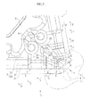
Fig. 1 is a perspective view which shows one embodiment of the present invention. -
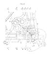
Fig. 2 is a planar view which shows the embodiment shown inFig. 1 when seen in a direction facing a rake face. -
Fig. 3 is a side view which shows the embodiment shown inFig. 2 when seen in a direction of an arrow F. -
Fig. 4 is a sectional view taken along a line of Y to Y inFig. 2 . -
Fig. 5 is a first enlarged planar view which shows the vicinity of a corner section of a cutting edge of the embodiment shown inFig. 1 when seen in a direction facing the rake face. -
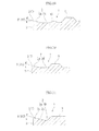
Fig. 6 is a side view when seen in a direction of an arrow G inFig. 5 . -
Fig. 7 is a side view when seen in a direction of an arrow H inFig. 5 . -
Fig. 8 is a sectional view taken along a line of Z to Z inFig. 5 . -
Fig. 9 is a sectional view taken along a line of V to V inFig. 5 . -
Fig. 10 is a sectional view taken along a line of T to T inFig. 5 . -
Fig. 11 is a sectional view taken along a line of S to S inFig. 5 . -
Fig. 12 is a second enlarged planar view which shows the vicinity of the corner section of the cutting edge of the embodiment shown inFig. 1 when seen from a direction facing the rake face. -
Fig. 13 is a sectional view taken along a line of Y to Y inFig. 12 (a sectional view orthogonal to acutting edge 5 when seen from a direction facing the rake face in a first region A). -
Fig. 14 is a sectional view which shows an O to O part inFig. 12 (a sectional view orthogonal to thecutting edge 5 when seen from a direction facing the rake face in the first region A). -
Fig. 15 is a sectional view which shows a P to P part inFig. 12 (a sectional view orthogonal to thecutting edge 5 when seen from a direction facing the rake face in a third region C). -
Fig. 16 is a sectional view which shows an X to X part inFig. 12 (a sectional view orthogonal to thecutting edge 5 when seen in a direction facing the rake face in the third region C). -
Fig. 17 is a sectional view which shows a U to U part inFig. 12 (a sectional view orthogonal to thecutting edge 5 when seen from a direction facing the rake face in the third region C). -
Fig. 18 is a sectional view which shows an N to N part inFig. 12 (a sectional view orthogonal to thecutting edge 5 when seen from a direction facing the rake face in a second region B). -
Fig. 19 is a sectional view which shows an M to M part inFig. 12 (a sectional view orthogonal to thecutting edge 5 when seen from a direction facing the rake face in the second region B). -
Fig. 20 is a sectional view which shows a W to W part inFig. 12 (a sectional view orthogonal to thecutting edge 5 when seen from a direction facing the rake face in the second region B). -
Fig. 21 is a sectional view which shows an L to L part inFig. 12 (a sectional view orthogonal to thecutting edge 5 when seen from a direction facing the rake face in the second region B) - One embodiment of the present invention is shown in
Fig. 1 to Fig. 21 . In the present embodiment, an insertmain body 1 is formed as a flat polygonal plate with a hard material such as a sintered hard alloy, a pair of polygonal faces are given as rake faces 2 and side faces around the rake faces 2 are given as flank faces 3. Further, anattachment hole 4 for attaching the insertmain body 1 to a holder of a indexable tool is formed on the insertmain body 1 so as to go through the insertmain body 1 in a thickness direction thereof (in a vertical direction inFig. 3, Fig. 4 ,Fig. 6 to Fig. 11 , andFig. 13 to Fig. 21 ) and opened at the center of therake face 2. In addition, a metal oxide layer such as Al2O3 or a carbon-nitride layer such as TiCN may be coated on the surface of the insertmain body 1 in a singular or a multi-layered form. It is also possible to coat a diamond layer thereon. - Further, a ridge section between adjacent flank faces 3 is formed in a shape of a raised cylindrical face which is smoothly in contact with the flank faces 3 and a
cutting edge 5 is formed at a ridge section between the flank faces 3 and therake face 2. Therefore, thecutting edge 5 is provided with acorner section 6 formed as a convex arc shape at a ridge section between the adjacent flank faces 3 when seen in a planar view from the thickness direction facing the rake face 2 (when seen in a planar view along the center line of the attachment hole 4). The present embodiment is also provided with a pair oflinear sections 7 which are in contact with thecorner section 6 at both ends of thecorner section 6 and extend linearly. Still further, the cutting insert of the present embodiment is given as a negative type insert in which theflank face 3 extends in the above-described thickness direction and is devoid of a relief angle. - Here, the insert
main body 1 of the present embodiment is formed as a flat rhomboid plate and a pair of rhomboid faces is given as rake faces 2. Therefore, thecorner section 6 of thecutting edge 5 is such that the one formed at a rhomboid acute-angled corner and the one formed at an obtuse-angled corner by the rake faces 2 are alternately placed in a circumferential direction. In the above-described cutting insert, as shown inFig. 5 andFig. 12 , thecorner section 6 formed at the acute-angled corner and thelinear sections 7 continuous thereto are mainly used in turning a workpiece. However, in a flat square cutting insert, it is possible to use corner sections formed at four right angle corners and linear sections continuous thereto. - In addition, a
boss section 8 which protrudes so as to rise in the thickness direction from therake face 2 is formed around an opening section of theattachment hole 4 at the center of therake face 2. Here, an upper face of theboss section 8 is at a position which protrudes in the thickness direction to a slightly greater extent than thecutting edge 5 on each of the rake faces 2 and given as a flat plane perpendicular to the thickness direction. Further, a side face of theboss section 8 intersects with an upper face obtusely and is given as an inclination face which becomes wider when moving from the upper face toward therake face 2. - Further, at a part which is close to the
boss section 8 between the acute-angled corner and theboss section 8, on both sides of a diagonal line connecting the rhomboid acute-angled corners formed by therake face 2, that is, on both sides of a bisector Q of thecorner section 6 at the acute-angled corner, a pair of protrudedsections 9 in the shape of a circular truncated cone are formed so as to rise and protrude from therake face 2. An upper face of each of the protrudedsections 9 is also at the same position as the upper face of theboss section 8 in the thickness direction and given as a flat plane perpendicular to the thickness direction. Further, in the present embodiment, the insertmain body 1 is formed so as to be symmetrical with respect to the bisector Q when seen in the planar view and also symmetrical in the thickness direction and, therefore, the insertmain body 1 has a shape of front/back-reversal symmetric. - Further, between the pair of protruded
sections 9 and thecorner section 6 of thecutting edge 5, aprotrusion streak 10 which protrudes so as to rise from therake face 2 is formed so as to extend along the bisector Q, with intervals kept between theprotruded sections 9 and thecorner section 6. Theprotrusion streak 10 is formed in such a manner that the width of theprotrusion streak 10 when seen in the planar view is gradually increased as being spaced away from thecorner section 6 along the bisector Q and the position of theprotrusion streak 10 is raised in two stages in the thickness direction of the upper face thereof. However, the upper face of a higher stage is positioned lower than theboss face 8 and the upper faces of the protrudedsections 9 in the thickness direction. Each of the upper faces of two stages of theprotrusion streak 10 is also given as a flat plane perpendicular to the thickness direction and a side face thereof is given as an inclination face which becomes wider along therake face 2. A ridge section between the upper face and the side face is chamfered to give a cross section which is in the shape of a convex arc. - On the other hand, the
rake face 2 is provided on the side of thecutting edge 5 and communicates with thecutting edge 5 without a land or the like in the present embodiment, provided with apositive rake face 2A which is curved to be thin in the thickness direction as being spaced away from thecutting edge 5 on a cross section perpendicular to thecutting edge 5 when seen in the planar view, thereby giving a positive rake angle θ, and also provided with aflat rake face 2B which is inside thepositive rake face 2A, giving a rake angle which is smaller than that of thepositive rake face 2A and extending at the rake angle of 0°, that is, in a direction perpendicular to the thickness direction on the cross section in the present embodiment. - However, the
protrusion streak 10 is provided in an extended manner on the bisector Q of thecorner section 6 and in the vicinity thereof. Thereby, noflat rake face 2B is present as shown inFig. 13 and Fig. 14 , or theflat rake face 2B is made extremely small as shown inFig. 15 . Further, a space between thepositive rake face 2A and theflat rake face 2B communicates with a recessed curved face more smoothly. - Next, regarding the
cutting edge 5, as shown inFig. 5 andFig. 12 when seen in the planar view, on the assumption that a part along thecorner section 6 is given as a first region A, a part along thelinear section 7 is given as a second region B and a part between the first region A and the second region B is given as a third region C, a rake angle θ of thecutting edge 5 which is formed by thepositive rake face 2A, that is, an inclination angle formed by thepositive rake face 2A in a direction perpendicular to the thickness direction on a cross section orthogonal to thecutting edge 5 when seen in the planar view is such that a rake angle θ3 of thecutting edge 5 in the third region C is greater than rake angles θ1, θ2 of thecutting edges 5 in the first region A and the second region B. - Here, in the present embodiment, the rake angle θ3 is to be constant in the third region C and the rake angle θ gradually decreased from the border D between the third region C and the first region A and the border E between the third region C and the second region B toward the first and the second regions as being spaced away from the third region C along the
cutting edges 5 in the first region A and the second region B. Next, in the first region A, the rake angle θ1 is to be constant at a part including acorner tip 6A on the bisector Q of the corner section 6 (a part from thecorner tip 6A to a cross section O to O inFig. 12 ). Furthermore, in the second region B, the rake angle θ2 is to be constant at a part which is a predetermined length on the side of the third region C (a part between a cross section N to N and a cross section W to W inFig. 12 ). - Further, the rake angle θ3 which is made large in the third region C is desirably set in a range of 15 to 25°. Furthermore, the rake angles θ1, θ2 which are made smaller than 15 to 25° in the first region A and the second region B are desirably set smaller than the rake angle θ3 in a range of 10 to 20°.
In the present embodiment, the rake angles θ1, θ2 which are constant in the first region A and the second region B are set to be 15° and are set equal with each other. The rake angle θ3 in the third region C is to be 20°. - Further, in the present embodiment, as shown in
Fig. 5 andFig. 12 when seen in the planar view, in the first, the second and the third regions, A, B, C, the third region C is such that the border D between the third region C and the first region A and the border E between the third region C and the second region B are disposed at a position of R x 3/4 (mm) and a position of R x 3/2 (mm) with respect to a radius R (mm) of thecorner section 6 from a tangent line J which is orthogonal to an extension line I of thelinear section 7 of thecutting edge 5 to thecorner section 6 and in contact with thecorner section 6, along the extension line I, when seen in the planar view, and the range of R x 3/4 (mm) to R x 3/2 (mm) is given as the third region C. Therefore, in the present embodiment, the third region C is given as a region which includes a contact point between thecorner section 6 and thelinear section 7 at the cutting edge 5 (a position of a Z to Z cross section inFig. 12 ). It is, however, acceptable that the border D between the third region C and the first region A is positioned in a range of R x 3/8 (mm) to R x 3/4 (mm) with respect to the radius R (mm) from the tangent line J, along the extension line I, when seen in the planar view. It is also acceptable that the border E between the third region C and the second region B is positioned in a range of R x 3/2 to R x 15/8 (mm) with respect to the radius R (mm) from the tangent line J, along the extension line I, when seen in the planar view. - Further, when seen in the planar view, the width of the
positive rake face 2A in a direction orthogonal to thecutting edge 5 is smallest in the third region C, as shown inFig. 5 andFig. 12 . Here, in the present embodiment, the width of thepositive rake face 2A in a direction orthogonal to thecutting edge 5 gradually decreases at a part where the rake angle is increased from 01 to 03 toward the border D between the third region C and the first region A in the first region A. Still further, the width of thepositive rake face 2A also gradually decreases in the third region C beyond the border D toward the third region C so as to be spaced away from the first region A and becomes smallest at a contact point between thecorner section 6 and thelinear section 7 in thecutting edge 5. - Next, from the contact point to the second region B, the width of the
positive rake face 2A is gradually increased beyond the border E between the second region B and the third region C up to a part where the rake angle is gradually decreased from θ3 to θ2. Furthermore, the width of thepositive rake face 2A is also constant at a part where the rake angle θ2 is constant in the second region B. At a part opposite of the third region C from the part where the rake angle θ2 is constant in the second region B, thepositive rake face 2A is provided in two stages made up of a firstpositive rake face 2a having a smaller rake angle (for example, 10°) than the rake angle θ2 on the side of thecutting edge 5 and a secondpositive rake face 2b which is inside of the firstpositive rake face 2a and has a rake angle θ2. A total width of thepositive rake face 2A is greater than the width of the part where the rake angle θ2 is to be constant. - On the other hand, when seen in a side view facing the
flank face 3, as shown inFig. 3 ,Fig. 6 and Fig. 7 , in the present embodiment, thecutting edge 5 is curved so as to put a dent in the thickness direction from thecorner tip 6A of thecorner section 6 through the border D between the first region A and the third region C and the border E between the second region B and the third region C up to a part where the rake angle θ2 starts to be constant in the second region B. Therefore, thecutting edge 5 is curved so as to put a dent in the thickness direction as moving toward the second region B from the first region A all over in the third region C. - Here, when seen in the above side view, the
cutting edge 5 is curved by giving a raised curve that rises in the thickness direction from thecorner tip 6A to the contact point between thecorner section 6 and thelinear section 7. On the other hand, thecutting edge 5 is curved so as to put a dent in the thickness direction by giving a recessed curve smoothly communicating with the raised curve from the contact point. That is, thecutting edge 5 is formed as a recessed and raised curve having an inflexion point in the third region C. - The
cutting edge 5 which dents in the thickness direction as described above is inclined upward so as to rise linearly in the thickness direction after giving a recessed curve as moving toward the opposite side of the third region C at the part where the rake angle θ2 is constant in the second region B. Furthermore, thecutting edge 5 extends on a flat plane perpendicular to the thickness direction via a raised curve at a part changing from the part where the rake angle θ2 is constant to a part where thepositive rake face 2A is constituted with the firstpositive rake face 2a and the secondpositive rake face 2b. Further, a position of the thickness direction on the flat plane where thecutting edge 5 extends is made equal to a position of thecutting edge 5 at thecorner tip 6A, which is lower than upper faces of theboss section 8 and the protrudedsection 9 but slightly higher than an upper face of the higher stage of theprotrusion streak 10. - Further, the
cutting edge 5 is curved and changes in such a manner that the width of thepositive rake face 2A where the rake angle θ3 is to be constant when seen in the planar view becomes smallest in the third region C, as described above. Thereby, in the present embodiment, theflat rake face 2B extending inside thepositive rake face 2A is such that the position of the thickness direction on a cross section orthogonal to thecutting edge 5 when seen in the planar view is also inclined downward so as to be gradually lower along thecutting edge 5 from the contact point between thecorner section 6 and thelinear section 7 where the width of thepositive rake face 2A becomes smallest toward the part where the rake angle θ2 starts to be constant in the second region B where the position of the thickness direction of thecutting edge 5 is lowest. Further, the depth of the thickness direction from thecutting edge 5 on the cross section is gradually increased. - On the other hand, the
flat rake face 2B in which the position of the thickness direction is lowered at the part where the rake angle θ2 of the second region B starts to be constant is such that the width of thepositive rake face 2A is constant at the part where the rake angle θ2 is to be constant and thecutting edge 5 is inclined upward so as to rise in the thickness direction as moving toward the opposite side of the third region C. Thereby, when seen in the planar view, the position of the thickness direction on the cross section orthogonal to thecutting edge 5 is also inclined so as to gradually rise as moving toward the opposite side of the third region C along thecutting edge 5. - Up to the contact point between the
corner section 6 and thelinear section 7 in the third region C from the first region A, theflat rake face 2B is such that the position of the thickness direction (height) thereof is made equal in a direction along thecutting edge 5 and in the present embodiment given as a flat plane perpendicular to the thickness direction. Further, the width of theflat rake face 2B formed in between from thepositive rake face 2A to theprotrusion streak 10 via the recessed curved face in a direction orthogonal to thecutting edge 5 when seen in the planar view is substantially constant at a part where theflat rake face 2B is inclined downward (a part where thepositive rake face 2A is gradually increased in width) as shown inFig. 5 andFig. 12 . - In the turning process using the above-described cutting insert, the
linear section 7 extending from thecorner section 6 of thecutting edge 5 which has cut into a workpiece to a feeding direction of thecorner section 6 cuts into the workpiece. In general, where a workpiece is subjected to light cutting under conditions that the depth of cut is 0.5 to 1.5 mm and the feed rate is 0.1 to 0.3 mm/rev, at thecutting edge 5 which cuts into the workpiece, a position of the tangent line J which is orthogonal to the extension line I of thelinear section 7 to thecorner section 6 and in contact with thecorner section 6 is practically a tip of the depth of cut of thecutting edge 5. A cutting boundary is substantially positioned in a range of R x 3/4 to R x 3/2 (mm) with respect to the radius R (mm) of thecorner section 6 in thelinear section 7 from the tangent line J, along the extension line I. - Next, in the above-described range, the
cutting edge 5 is given as the third region of which the rake angle θ3 is smaller than the rake angle θ1 of the first region A and the rake angle θ2 of the second region B and imparted excellent sharpness. The thus described third region C is positioned at a cutting boundary, by which, for example, when a difficult-to-cut material such as stainless steel is subjected to turning, occurrence of burrs can be suppressed at the cutting boundary. Therefore, it is possible to avoid such a negative circle in that thecutting edge 5 cuts into the burrs which have undergone work hardening in association with feeding and abnormal wear of thecutting edge 5 proceeds and thecutting edge 5 is thereby decreased in sharpness with burrs more likely to occur. It is thus possible to perform stable and efficient light cutting. - On the other hand, in the first region A and the second region B other than the third region C, the rake angles θ1, θ2 of the
cutting edges 5 are made smaller than the rake angle θ3 in the third region C. Thereby, these cuttingedges 5 can be inversely increased in wedge angle to have a great cutting edge strength. Therefore, thecutting edge 5 as a whole retains sufficient fracturing resistance and chipping resistance and reduction in insert life due to the fracturing and the chipping is also prevented, by which it is possible to provide a cutting insert longer in service life. - Further, in the cutting insert of the present embodiment, the
rake face 2 is provided with thepositive rake face 2A which is on the side of thecutting edge 5 and gives the rake angles θ(θ1 to θ3) in the first, the second and the third regions A, B, C and theflat rake face 2B which is inside of thepositive rake face 2A and gives a rake angle smaller than the rake angles θ of thepositive rake face 2A or giving a rake angle of 0° in particular in the present embodiment. In the third region C having agreater rake angle 03, the width thereof in a direction orthogonal to thecutting edge 5 of thepositive rake face 2A when seen in a planar view from the direction facing therake face 2 along the thickness direction is made smallest. In other words, theflat rake face 2B having a smaller rake angle is in a position closest to thecutting edge 5. - Therefore, according to the present embodiment, in the third region C in which the greater rake angle θ3 is likely to increase sharpness but impair strength and rigidity of the
cutting edge 5, theflat rake face 2B having a smaller rake angle is brought close to thecutting edge 5, by which the insertmain body 1 can be increased in thickness at a position close to thecutting edge 5. Thus, what is called back metal can be ensured to prevent thecutting edge 5 from being unnecessarily reduced in strength and rigidity. On the other hand, in the first region A and the second region B, thepositive rake face 2A has a large width, and theflat rake face 2B having a smaller rake angle than the rake angles θ1, θ2 which are smaller than the rake angle θ3 and theprotrusion streak 10 are kept away from thecutting edge 5. Thus, there is no chance that the cutting force is unnecessarily increased. - In the present embodiment, the rake angle of the
flat rake face 2B on a cross section orthogonal to thecutting edge 5 when seen in the planar view is given as 0° and extends perpendicularly in the thickness direction of the insertmain body 1. However, if smaller than therake angle 03 of thecutting edge 5 by thepositive rake face 2A in the third region C, it is acceptable that theflat rake face 2B is not necessarily flat in a strict sense and, as with thepositive rake face 2A, theflat rake face 2B is curved so as to put a dent in the thickness direction as moving toward the inside of therake face 2. - On the other hand, in the present embodiment, when seen in a side view facing the
flank face 3, thecutting edge 5 is curved so as to put a dent toward the thickness direction as moving toward the second region B from the first region A in the third region C. As compared with a case where, for example, thecutting edge 5 is as a whole disposed on a flat plane perpendicular to the thickness direction, a cutting edge inclination can be set so as to be great to the side of a positive angle, thereby lowering the cutting force. As a result, together with the fact that thecutting edge 5 in the third region C is increased inrake angle 03, thecutting edge 5 in the third region C is further improved in sharpness, thus making it possible to suppress the occurrence of burrs more reliably. - Moreover, chips generated on light cutting having a cutting boundary in the third region C collide with side faces of the
protrusion streak 10 protruding inside thereof after passing through thepositive rake face 2A of therake face 2 to theflat rake face 2B and are separated and treated. However, in the present embodiment, from the contact point between thecorner section 6 and thelinear section 7 at thecutting edge 5 positioned in the third region C to a part where the rake angle θ2 on the side of the third region C in the second region B where a position of the thickness direction at thecutting edge 5 becomes lowest starts to be constant, the position of the thickness direction at theflat rake face 2B on a cross section orthogonal to thecutting edge 5 when seen in the planar view is inclined downward so as to be gradually lower along thecutting edge 5. Further, the depth of theflat rake face 2B in the thickness direction from thecutting edge 5 on the above described cross section is also gradually increased. - That is, at the part on the side of the third region C in the second region B where the depth of the
flat rake face 2B from thecutting edge 5 is gradually increased, a pocket which houses chips can be reliably increased in capacity. Thus, according to the present embodiment, chips generated in particular from the vicinity of a cutting boundary positioned in the third region C can be smoothly guided into the large capacity pocket and duly treated without clogging or the like. Therefore, in the present embodiment, it is also possible to prevent such a situation that burrs easily occur due to clogging of chips generated in the vicinity of the cutting boundary. - In the present embodiment, the insert
main body 1 is made symmetrical with respect to the bisector Q of thecorner section 6 and available in what is called a free-type cutting insert which can be attached to a holder of a right-handed indexable tool and also to a holder of a left-handed indexable tool. It is acceptable that the first region A, the second region B and the third region C including the third region C of which the rake angle θ is made greater are set for thecutting edge 5 which covers an area from one end of thecorner section 6 which cuts into a workpiece to thelinear section 7 at least facing to a feed direction. Therefore, the present invention is also applicable in what is called a handed cutting insert in which such first region A, the second region B and the third region C are not set to thecutting edge 5 extending from the other end of thecorner section 6, in contrast to the above description. - Next, a range in which the third region C is positioned will be demonstrated for its effect by referring to an example. In the present example, six types of cutting inserts were manufactured according to the above described embodiment in which changing a range where the third region C was positioned in a direction from the tangent line J orthogonal to the extension line I of the
linear section 7 to thecorner section 6 and in contact with thecorner section 6 and along the extension line I. These cutting inserts are referred to as examples 1 to 6. - In these cutting inserts of the examples 1 to 6, the model number was CNMG120408, the nominal radius of
corner section 6 was 0.8 (mm) and the actually measured radius R was 0.794 (mm). As described above, therake angle 03 of thecutting edge 5 in the third region C was 20°, the rake angles θ1, θ2 in the first region A and the second region B were to be constant and each of which was 15°. Further, the insertmain body 1 was made with a sintered hard alloy (type M30 according to JIS B 4053-1998), the surface of which was coated by a CVD method with about a 5 µm-thick composite layer prepared by coating Al2O3 on TiCN. - Next, the cutting inserts of these examples 1 to 6 were used to lightly cut a workpiece (stainless steel) by turning an outer diameter. Comparison was made for the occurrence of burrs and fracturing resistance of each cutting edge at that time. The results and overall evaluation are shown in Table 1 together with ranges of the examples 1 to 6 in which the third region C was positioned.
-
[Table 1] Range of third region (mm) Evaluation of occurrence of burrs Evaluation of fracturing resistance Overall evaluation Example 1 0.3 - 1.2 EX FA FA Example 2 0.3 - 1.5 EX FA FA Example 3 0.6 - 1.2 EX EX EX Example 4 0.6 - 1.5 EX FA FA Example 5 0.9 - 1.2 FA EX FA Example 6 0.9 - 1.5 FA EX FA - Further, the workpiece was a round bar made with SUS 304 (hardness of 169HB) and subjected to wet cutting by using cutting fluid (
A3 type 1, JIS K 2241: 2000). When the occurrence of burrs was compared, the workpiece with an outer diameter of 57.6 mm was subjected to continuous cutting over a distance of 0.10 m in a rotation-axis direction of the workpiece under cutting conditions that the depth of cut was 1.0 mm, the feed rate was 0.1 mm/rev and the cutting speed was 150 m/min. - Further, when the fracturing resistance was compared, harder conditions were applied. Specifically, one 10 mm-wide flute was formed on an outer circumference of the workpiece with an outer diameter of 44.8 mm in the rotation-axis direction of the workpiece so as to cause interrupted cutting. The workpiece was cut under cutting conditions that the depth of cut was 1.5 mm, the feed rate was 0.2 mm/rev and the cutting speed was 150 m/min over a distance of 0.10 m in the rotation-axis direction of the workpiece.
- Still further, evaluation was made under the following criteria. Regarding the occurrence of burrs, a case where no occurrence of burrs was visually confirmed was evaluated "EX (excellent)" and a case where partial occurrence of burrs was confirmed was evaluated "FA (fair)." Further, regarding the fracturing resistance, a case where no chipping was found on cutting was evaluated "EX (excellent)" and a case where chipping was found but slight in extent and the workpiece was allowed to be cut up to the above described cutting length was evaluated "FA (fair)". Overall evaluation was made based on a lower evaluation among the above described evaluation results.
- With reference to the results of Table 1, regarding the occurrence of burrs, partial occurrence of burrs was found in the examples 5 and 6 in which the border D between the first region A and the third region C was close to a cutting boundary, and no continuous occurrence of burrs was found. Further, no occurrence of burrs was confirmed in the examples 1 to 4 other than these examples.
- On the other hand, regarding the fracturing resistance, there was found no chipping or fracturing which resulted in cutting failure. However, slight chipping was found on confirmation after completion of cutting in the examples 1, 2 and 4 in which a range of the third region C having a greater rake angle θ3 was 0.7 mm or more which was longer than 3/4 of the radius R (mm) of the
corner section 6. In contrast, no chipping was found in the examples 3, 5, and 6 in which the range of the third region C was 0.6 mm or less which was 3/4 of the radius R (mm) of thecorner section 6. According to the overall evaluation, the example 3 was evaluated highest in which the third region C was in a range of R x 3/4 to R x 3/2 (mm) with respect to the radius R (mm) of the corner section. - The present invention relates to a cutting insert which is provided with an insert main body having a rake face and a flank face and a cutting edge formed at a ridge section between the rake face and the flank face in the insert main body.
According to the cutting insert of the present invention, on light cutting of a difficult-to-cut material such as stainless steel, the cutting edge was prevented from fracturing and chipping and also improved in sharpness at a cutting boundary to suppress the occurrence of burrs, thus making it possible to avoid abnormal wear and perform an efficient turning process. -
- 1:
- insert main body
- 2:
- rake face
- 2A:
- positive rake face
- 2B:
- flat rake face
- 3:
- flank face
- 5:
- cutting edge
- 6:
- corner section
- 7:
- linear section
- A:
- first region
- B:
- second region
- C:
- third region
- D:
- border between third region C and first region A
- E:
- border between third region C and second region B
- Q:
- bisector of
corner section 6 - I:
- extension line of
linear section 7 to cornersection 6 - J:
- tangent line orthogonal to extension line M and in contact with corner section
- θ:
- rake angle of
positive rake face 2A - θ1:
- rake angle in first region A
- θ2:
- rake angle in second region B
- θ3:
- rake angle in third region C
Claims (5)
- A cutting insert comprising:an insert main body having a rake face and a flank face; anda cutting edge which is formed at a ridge section between the rake face and the flank face in the insert main body and provided with a corner section which forms a convex arc shape when seen in a planar view from a direction facing the rake face and a linear section which is in contact with the corner section at least at one end of the corner section and extends linearly, whereinthe cutting edge is provided with a first region along the corner section when seen in the planar view, a second region along the linear section and a third region positioned between the first region and the second region, anda rake angle of the cutting edge in the third region is greater than rake angles of the cutting edges in the first region and the second region.
- The cutting insert according to Claim 1, wherein
the rake angle of the cutting edge gradually decreases from borders of the third region, which are between the third region and the first region and between the third region and the second region, toward the first and the second regions along the respective cutting edges in the first and the second regions,
the border between the third region and the first region is positioned in a range of R x 3/8 to R x 3/4 (mm) with respect to the radius R (mm) of the corner section from a tangent line which is orthogonal to an extension line of the linear section to the corner section and in contact with the corner section, along the extension line, when seen in the planar view, and
the border between the third region and the second region is positioned in a range of R x 3/2 to R x 15/8 (mm) with respect to the radius R (mm) of the corner section from the tangent line, along the extension line, when seen in the planar view. - The cutting insert according to Claim 2, wherein
the third region is positioned in a range of R x 3/4 to R x 3/2 (mm) with respect to the radius R (mm) of the corner section from the tangent line orthogonal to the extension line of the linear section to the corner section and in contact with the corner section, along the extension line, when seen in the planar view. - The cutting insert according to any one of Claims 1 to 3, wherein
a positive rake face which is on the side of the cutting edge and forms the rake angle and a flat rake face which is inside of the positive rake face and smaller in rake angle than the positive rake face are included in the rake face, and
the width of the positive rake face in a direction orthogonal to the cutting edge in the third region is the smallest among the regions, when seen in the planar view. - The cutting insert according to any one of Claims 1 to 4, wherein
the cutting edge included in the third region is curved between the first and second regions so as to put a dent in the rake face when seen in a side view facing the flank face.
Applications Claiming Priority (3)
| Application Number | Priority Date | Filing Date | Title |
|---|---|---|---|
| JP2010254999 | 2010-11-15 | ||
| JP2011246397A JP5853613B2 (en) | 2010-11-15 | 2011-11-10 | Cutting insert |
| PCT/JP2011/076305 WO2012067114A1 (en) | 2010-11-15 | 2011-11-15 | Cutting insert |
Publications (2)
| Publication Number | Publication Date |
|---|---|
| EP2641677A1 true EP2641677A1 (en) | 2013-09-25 |
| EP2641677A4 EP2641677A4 (en) | 2016-03-02 |
Family
ID=46084038
Family Applications (1)
| Application Number | Title | Priority Date | Filing Date |
|---|---|---|---|
| EP11840956.4A Withdrawn EP2641677A4 (en) | 2010-11-15 | 2011-11-15 | Cutting insert |
Country Status (6)
| Country | Link |
|---|---|
| US (1) | US9364898B2 (en) |
| EP (1) | EP2641677A4 (en) |
| JP (1) | JP5853613B2 (en) |
| KR (1) | KR101793768B1 (en) |
| CN (1) | CN103209792B (en) |
| WO (1) | WO2012067114A1 (en) |
Cited By (3)
| Publication number | Priority date | Publication date | Assignee | Title |
|---|---|---|---|---|
| EP3006140A1 (en) | 2014-10-08 | 2016-04-13 | Sandvik Intellectual Property AB | Turning tool cutting insert and turning tool |
| US10213839B2 (en) | 2014-09-18 | 2019-02-26 | Kyocera Corporation | Cutting insert, cutting tool, and method of manufacturing machined product |
| EP3539698A1 (en) * | 2018-03-15 | 2019-09-18 | Tungaloy Corporation | Cutting insert, holder, and cutting tool that includes cutting insert |
Families Citing this family (16)
| Publication number | Priority date | Publication date | Assignee | Title |
|---|---|---|---|---|
| RU2532612C2 (en) * | 2010-05-11 | 2014-11-10 | Тунгалой Корпорейшн | Cutter plate |
| CN103534051A (en) * | 2011-05-03 | 2014-01-22 | 戴蒙得创新股份有限公司 | Insert with a wiper to induce chip thinning on a leading edge |
| CN104136158B (en) * | 2012-02-29 | 2017-03-01 | 京瓷株式会社 | The manufacture method of cutting insert, cutting element and machining thing |
| US10220448B2 (en) * | 2012-02-29 | 2019-03-05 | Kyocera Corporation | Cutting insert, cutting tool, and method of manufacturing machined product |
| US8939684B2 (en) * | 2012-05-15 | 2015-01-27 | Iscar, Ltd. | Cutting insert with chip-control arrangement having recess depths and projection heights which increase with distance from cutting edge |
| SE1350348A1 (en) | 2013-03-20 | 2014-09-21 | Sandvik Intellectual Property | Double-sided, indexable lathe insert |
| US9409237B2 (en) * | 2013-09-16 | 2016-08-09 | Iscar, Ltd. | Finish depth turning insert comprising a chip control arrangement |
| WO2016043127A1 (en) * | 2014-09-16 | 2016-03-24 | 住友電気工業株式会社 | Cutting insert and manufacturing method therefor |
| JP6607472B2 (en) * | 2016-08-31 | 2019-11-20 | 住友電工ハードメタル株式会社 | Cutting insert |
| US11446745B2 (en) * | 2018-09-27 | 2022-09-20 | Iscar, Ltd. | Turning insert having peninsula and island protrusions, and turning tool |
| US11040404B2 (en) * | 2018-10-11 | 2021-06-22 | Sumitomo Electric Hardmetal Corp. | Cutting insert and boring tool |
| JP2020069598A (en) * | 2018-10-31 | 2020-05-07 | 京セラ株式会社 | Cutting insert, cutting tool and manufacturing method for cutting work-piece |
| EP3702075B1 (en) * | 2019-02-28 | 2023-12-20 | AB Sandvik Coromant | Turning insert for metal cutting |
| WO2021095520A1 (en) * | 2019-11-13 | 2021-05-20 | 京セラ株式会社 | Cutting insert, cutting tool, and method for manufacturing cut workpiece |
| JP7344385B2 (en) * | 2020-05-26 | 2023-09-13 | 京セラ株式会社 | Manufacturing method for cutting inserts, cutting tools, and cut products |
| CN114309682A (en) | 2020-09-30 | 2022-04-12 | 肯纳金属公司 | Cutting insert |
Family Cites Families (15)
| Publication number | Priority date | Publication date | Assignee | Title |
|---|---|---|---|---|
| JPS6342965Y2 (en) | 1980-09-04 | 1988-11-10 | ||
| CH667407A5 (en) * | 1986-03-27 | 1988-10-14 | Stellram Sa | STRAWBERRY WITH REMOVABLE CUTTING INSERTS. |
| FR2624414A1 (en) * | 1987-12-11 | 1989-06-16 | Safety | CUTTING PLATE WITH SAFETY CUTTING AREAS |
| JP3269217B2 (en) | 1992-10-26 | 2002-03-25 | 三菱マテリアル株式会社 | Indexable tip |
| SE500719C2 (en) * | 1993-01-27 | 1994-08-15 | Sandvik Ab | Cut with twisted chip surface |
| JP3366751B2 (en) * | 1994-10-19 | 2003-01-14 | 東芝タンガロイ株式会社 | Indexable tip |
| US6065907A (en) * | 1998-12-23 | 2000-05-23 | Kennametal Inc. | Cutting insert with chip control |
| JP2001038507A (en) | 1999-07-29 | 2001-02-13 | Toshiba Tungaloy Co Ltd | Throw-away tip |
| JP2001157903A (en) * | 1999-11-29 | 2001-06-12 | Mitsubishi Materials Corp | Throw-away tip |
| JP4613404B2 (en) * | 2000-08-30 | 2011-01-19 | 株式会社タンガロイ | Throwaway tip |
| JP3812473B2 (en) * | 2001-11-20 | 2006-08-23 | 三菱マテリアル株式会社 | Throwaway tip |
| JP4923569B2 (en) * | 2005-12-27 | 2012-04-25 | 株式会社タンガロイ | Throwaway tip |
| CN101720264B (en) * | 2007-06-26 | 2011-06-01 | 特固克有限会社 | Cutting insert with protrusions formed at corner area thereof |
| WO2009096516A1 (en) * | 2008-01-30 | 2009-08-06 | Kyocera Corporation | Cutting insert, cutting tool, and cutting method |
| JP5158490B2 (en) * | 2008-03-06 | 2013-03-06 | 住友電工ハードメタル株式会社 | Replaceable cutting edge |
-
2011
- 2011-11-10 JP JP2011246397A patent/JP5853613B2/en active Active
- 2011-11-15 WO PCT/JP2011/076305 patent/WO2012067114A1/en active Application Filing
- 2011-11-15 KR KR1020137012286A patent/KR101793768B1/en active IP Right Grant
- 2011-11-15 EP EP11840956.4A patent/EP2641677A4/en not_active Withdrawn
- 2011-11-15 US US13/885,232 patent/US9364898B2/en active Active
- 2011-11-15 CN CN201180054744.6A patent/CN103209792B/en active Active
Cited By (4)
| Publication number | Priority date | Publication date | Assignee | Title |
|---|---|---|---|---|
| US10213839B2 (en) | 2014-09-18 | 2019-02-26 | Kyocera Corporation | Cutting insert, cutting tool, and method of manufacturing machined product |
| EP3006140A1 (en) | 2014-10-08 | 2016-04-13 | Sandvik Intellectual Property AB | Turning tool cutting insert and turning tool |
| WO2016055468A1 (en) | 2014-10-08 | 2016-04-14 | Sandvik Intellectual Property Ab | Turning tool cutting insert and turning tool |
| EP3539698A1 (en) * | 2018-03-15 | 2019-09-18 | Tungaloy Corporation | Cutting insert, holder, and cutting tool that includes cutting insert |
Also Published As
| Publication number | Publication date |
|---|---|
| WO2012067114A1 (en) | 2012-05-24 |
| JP5853613B2 (en) | 2016-02-09 |
| EP2641677A4 (en) | 2016-03-02 |
| JP2012121131A (en) | 2012-06-28 |
| US9364898B2 (en) | 2016-06-14 |
| CN103209792A (en) | 2013-07-17 |
| US20130236258A1 (en) | 2013-09-12 |
| CN103209792B (en) | 2016-01-27 |
| KR20130122745A (en) | 2013-11-08 |
| KR101793768B1 (en) | 2017-11-03 |
Similar Documents
| Publication | Publication Date | Title |
|---|---|---|
| EP2641677A1 (en) | Cutting insert | |
| EP1702702B1 (en) | Face milling insert | |
| EP2435204B1 (en) | Cutting insert | |
| KR101798695B1 (en) | Cutting insert | |
| KR101720553B1 (en) | Cutting insert, cutting tool, and method for manufacturing cut product | |
| JP5206905B2 (en) | Cutting insert | |
| EP2412464B2 (en) | Milling cutter | |
| KR101233838B1 (en) | Cutting insert | |
| EP2495058B1 (en) | Cutting insert | |
| WO2011001939A1 (en) | Cutting insert, cutting tool, and manufacturing method for cut product using the same | |
| KR100558249B1 (en) | Cutting insert | |
| EP2842668A1 (en) | Tool made of cubic boron nitride sintered body | |
| US20190143419A1 (en) | Cutting insert | |
| AU2004284049A1 (en) | Cutting insert for high feed face milling | |
| EP2832477A1 (en) | Cutting insert | |
| KR20120050483A (en) | Cutting insert and cutting tool | |
| JP4784378B2 (en) | Super high pressure sintered body cutting tool | |
| JP2017193001A (en) | Cutting insert and cutting tool | |
| JP2017193002A (en) | Cutting insert and cutting tool | |
| KR102493702B1 (en) | Negative Finish Turning Inserts with Chip Forming Device | |
| CN114951720B (en) | Cutting insert | |
| CN116000331A (en) | Indexable turning tool and indexable turning tool | |
| JP4119967B2 (en) | Blade-replaceable rotary tool | |
| JP2007290057A (en) | Ultra-high pressure sintered body cutting tool | |
| JP2015077647A (en) | Forward path and return path longitudinal feed insert, and cutting-edge replacement type rotary cutting tool mounting the insert |
Legal Events
| Date | Code | Title | Description |
|---|---|---|---|
| PUAI | Public reference made under article 153(3) epc to a published international application that has entered the european phase |
Free format text: ORIGINAL CODE: 0009012 |
|
| 17P | Request for examination filed |
Effective date: 20130517 |
|
| AK | Designated contracting states |
Kind code of ref document: A1 Designated state(s): AL AT BE BG CH CY CZ DE DK EE ES FI FR GB GR HR HU IE IS IT LI LT LU LV MC MK MT NL NO PL PT RO RS SE SI SK SM TR |
|
| DAX | Request for extension of the european patent (deleted) | ||
| RA4 | Supplementary search report drawn up and despatched (corrected) |
Effective date: 20160128 |
|
| RIC1 | Information provided on ipc code assigned before grant |
Ipc: B23B 27/14 20060101AFI20160122BHEP Ipc: B23B 27/00 20060101ALI20160122BHEP |
|
| GRAP | Despatch of communication of intention to grant a patent |
Free format text: ORIGINAL CODE: EPIDOSNIGR1 |
|
| INTG | Intention to grant announced |
Effective date: 20180703 |
|
| STAA | Information on the status of an ep patent application or granted ep patent |
Free format text: STATUS: THE APPLICATION IS DEEMED TO BE WITHDRAWN |
|
| 18D | Application deemed to be withdrawn |
Effective date: 20181114 |