EP2641521A2 - Pompe de précharge adaptative - Google Patents
Pompe de précharge adaptative Download PDFInfo
- Publication number
- EP2641521A2 EP2641521A2 EP13160073.6A EP13160073A EP2641521A2 EP 2641521 A2 EP2641521 A2 EP 2641521A2 EP 13160073 A EP13160073 A EP 13160073A EP 2641521 A2 EP2641521 A2 EP 2641521A2
- Authority
- EP
- European Patent Office
- Prior art keywords
- disc
- chamber
- slide
- sleeve member
- slide member
- Prior art date
- Legal status (The legal status is an assumption and is not a legal conclusion. Google has not performed a legal analysis and makes no representation as to the accuracy of the status listed.)
- Granted
Links
- 230000003044 adaptive effect Effects 0.000 title 1
- 230000036316 preload Effects 0.000 title 1
- 239000012530 fluid Substances 0.000 claims abstract description 71
- 238000004891 communication Methods 0.000 claims description 11
- 239000007788 liquid Substances 0.000 claims description 5
- 230000002093 peripheral effect Effects 0.000 claims 2
- 238000007789 sealing Methods 0.000 abstract description 5
- 230000007246 mechanism Effects 0.000 description 5
- 230000008901 benefit Effects 0.000 description 2
- 230000004048 modification Effects 0.000 description 2
- 238000012986 modification Methods 0.000 description 2
- 239000000344 soap Substances 0.000 description 2
- 230000003213 activating effect Effects 0.000 description 1
- 230000004913 activation Effects 0.000 description 1
- 230000000295 complement effect Effects 0.000 description 1
- 230000006835 compression Effects 0.000 description 1
- 238000007906 compression Methods 0.000 description 1
- 230000008878 coupling Effects 0.000 description 1
- 238000010168 coupling process Methods 0.000 description 1
- 238000005859 coupling reaction Methods 0.000 description 1
- 238000007599 discharging Methods 0.000 description 1
- 238000002347 injection Methods 0.000 description 1
- 239000007924 injection Substances 0.000 description 1
- 238000001746 injection moulding Methods 0.000 description 1
- 238000004519 manufacturing process Methods 0.000 description 1
- 239000000463 material Substances 0.000 description 1
- 239000013518 molded foam Substances 0.000 description 1
- 238000005086 pumping Methods 0.000 description 1
- 230000007480 spreading Effects 0.000 description 1
- 238000013022 venting Methods 0.000 description 1
Images


Classifications
-
- F—MECHANICAL ENGINEERING; LIGHTING; HEATING; WEAPONS; BLASTING
- F04—POSITIVE - DISPLACEMENT MACHINES FOR LIQUIDS; PUMPS FOR LIQUIDS OR ELASTIC FLUIDS
- F04B—POSITIVE-DISPLACEMENT MACHINES FOR LIQUIDS; PUMPS
- F04B23/00—Pumping installations or systems
- F04B23/02—Pumping installations or systems having reservoirs
- F04B23/025—Pumping installations or systems having reservoirs the pump being located directly adjacent the reservoir
- F04B23/028—Pumping installations or systems having reservoirs the pump being located directly adjacent the reservoir the pump being mounted on top of the reservoir
-
- A—HUMAN NECESSITIES
- A47—FURNITURE; DOMESTIC ARTICLES OR APPLIANCES; COFFEE MILLS; SPICE MILLS; SUCTION CLEANERS IN GENERAL
- A47K—SANITARY EQUIPMENT NOT OTHERWISE PROVIDED FOR; TOILET ACCESSORIES
- A47K5/00—Holders or dispensers for soap, toothpaste, or the like
- A47K5/06—Dispensers for soap
- A47K5/12—Dispensers for soap for liquid or pasty soap
- A47K5/1202—Dispensers for soap for liquid or pasty soap dispensing dosed volume
- A47K5/1204—Dispensers for soap for liquid or pasty soap dispensing dosed volume by means of a rigid dispensing chamber and pistons
- A47K5/1207—Dispensing from the bottom of the dispenser with a vertical piston
-
- B—PERFORMING OPERATIONS; TRANSPORTING
- B05—SPRAYING OR ATOMISING IN GENERAL; APPLYING FLUENT MATERIALS TO SURFACES, IN GENERAL
- B05B—SPRAYING APPARATUS; ATOMISING APPARATUS; NOZZLES
- B05B11/00—Single-unit hand-held apparatus in which flow of contents is produced by the muscular force of the operator at the moment of use
- B05B11/01—Single-unit hand-held apparatus in which flow of contents is produced by the muscular force of the operator at the moment of use characterised by the means producing the flow
- B05B11/10—Pump arrangements for transferring the contents from the container to a pump chamber by a sucking effect and forcing the contents out through the dispensing nozzle
- B05B11/1001—Piston pumps
-
- B—PERFORMING OPERATIONS; TRANSPORTING
- B05—SPRAYING OR ATOMISING IN GENERAL; APPLYING FLUENT MATERIALS TO SURFACES, IN GENERAL
- B05B—SPRAYING APPARATUS; ATOMISING APPARATUS; NOZZLES
- B05B11/00—Single-unit hand-held apparatus in which flow of contents is produced by the muscular force of the operator at the moment of use
- B05B11/01—Single-unit hand-held apparatus in which flow of contents is produced by the muscular force of the operator at the moment of use characterised by the means producing the flow
- B05B11/10—Pump arrangements for transferring the contents from the container to a pump chamber by a sucking effect and forcing the contents out through the dispensing nozzle
- B05B11/1097—Pump arrangements for transferring the contents from the container to a pump chamber by a sucking effect and forcing the contents out through the dispensing nozzle with means for sucking back the liquid or other fluent material in the nozzle after a dispensing stroke
Definitions
- This invention relates to piston pumps and, more particularly, piston pumps in which a flexible seal on a piston engages with a chamber wall to maintain pressure within a chamber by which fluid is pumped from the chamber.
- the present invention provides a piston pump having a reciprocating piston pump arrangement in which in a dispensing stroke in which fluid is pressurized in a chamber to dispense fluid, a piston slide member is urged into a sealing disc of a piston sleeve member to increase the extent to which the sealing disc provides a seal with a wall of the chamber against fluid leaking out past the seal disc.
- An object of the present invention is to provide a piston pump which resists the tendency of seals to leak.
- An object of the present invention is to provide a fluid dispenser with a piston pump for dispensing fluid including a piston carrying a movable slide member which slides to reduces the tendency of a seal to leak between the piston and a piston chamber wall.
- the present invention provides a pump for dispensing liquid from a reservoir comprising:
- a piston chamber-forming member having a chamber disposed about an axis, the chamber having a diameter, a chamber wall, an inner end and an open outer end,
- a one-way valve between the reservoir and the chamber permitting fluid flow through the inner end of said chamber, only from the reservoir to the chamber,
- a piston sleeve member slidably received in the chamber of the piston chamber-forming member for reciprocal axial inward and outward movement therein in a stroke of movement between an extended position and a retracted position
- said sleeve member having an axially extending hollow sleeve stem having a central bore therethrough from an inner end to an outlet proximate an outer end,
- the outer disc having a cam surface annularly thereabout outwardly of the sleeve stem
- a piston slide member having an axially extending hollow slide stem having a central passage closed at an inner end and open at an outer end,
- the slide member coupled to the sleeve member for limited coaxial sliding movement of the slide member relative the sleeve member between an extension condition and a retraction condition with the slide stem coaxially disposed relative the bore, the passage in communication with the bore and the spreader disc located in the chamber inwardly of the outer disc,
- the inner disc engaging the chamber wall axially inwardly of the spreader disc to substantially prevent fluid flow in the chamber past the inner disc in an inward direction but with the inner disc elastically deforming away from the chamber wall to permit fluid flow in the chamber past the inner disc in an outward direction,
- the spreader disc having a camming surface in opposition to the cam surface of the outer disc
- a cycle of operation comprises moving in a retraction stroke from the extended position to the retracted position and moving in an extension stroke from the retracted position to the extended position, in the extension stroke a vacuum is created in the chamber between the inner disc and the one-way valve by which both (a) the slide member is moved relative the sleeve member to the extension condition and (b) fluid is drawn from the reservoir past the one-way valve to between the inner disc and the one-way valve, in the retraction stroke pressure is created in the chamber between the inner disc and the one-way valve by which both (a) the slide member is moved relative the sleeve member to the retraction condition and (b) fluid is discharged from between the inner disc and the one-way valve past the inner disc to between the inner disc and the outer disc and via the inlet, the passage and the bore out the outlet.
- the sleeve is in the extended position with the slide in the extension condition, and at the end of a retraction stroke and the beginning of an extension stroke the sleeve is in the retracted position with the slide in the retraction condition.
- Figure 1 is a partially cut-away side view of an embodiment of a liquid dispenser with a reservoir and a pump assembly in accordance with the present invention
- Figure 2 is a schematic cross-sectional side view of a pump assembly in accordance with a first embodiment of the present invention at the end of an extension stroke with a piston sleeve member in a fully extended position and a piston slide member in an extension condition;
- Figure 3 is a view identical to that in Figure 2 but during a retraction stroke with the piston sleeve member in an intermediate position between the fully extended position and the fully retracted position and the piston slide member in a retraction condition;
- Figure 4 is a view identical to that in Figure 2 but at the end of a retraction stroke with the piston sleeve member in a fully retracted position and the slide member in a retraction condition;
- Figure 5 is a view identical to that in Figure 2 but during an extension stroke with the piston sleeve member in an intermediate position between the fully retracted position and the fully extended position and the piston slide member in an extension condition;
- Figure 6 is a schematic cross-sectional side view of a pump assembly in accordance with a second embodiment of the present invention during an extension stroke with the slide member in an extension condition;
- Figure 7 is a schematic cross-sectional side view of a pump assembly in accordance with a third embodiment of the present invention during an extension stroke with the slide member in an extension condition;
- Figure 8 is a schematic cross-sectional side view of a pump assembly in accordance with a fourth embodiment of the present invention during an extension stroke with the slide member in an extension condition;
- Figure 9 is a schematic cross-sectional side view of a pump assembly in accordance with a fifth embodiment of the present invention at the end of a retraction stroke with the piston sleeve member in a fully retracted position and the slide member in a retraction condition.
- FIG. 1 shows a liquid soap dispenser generally indicated 170 utilizing a pump assembly 10 coupled to the neck 58 of a sealed, collapsible container or reservoir 60 containing liquid hand soap 68 to be dispensed.
- Dispenser 170 has a housing generally indicated 178 to receive and support the pump assembly 10 and the reservoir 60. Housing 178 is shown with a back plate 180 for mounting the housing, for example, to a building wall 181.
- a bottom support plate 184 extends forwardly from the back plate to support and receive the reservoir 60 and pump assembly 10.
- the pump assembly 10 is only schematically shown in Figure 1 , as including a slidable piston 14. As shown, bottom support plate 184 has a circular opening 186 therethrough.
- the reservoir 60 sits supported on shoulder 179 of the support plate 184 with the neck 58 of the reservoir 60 extending through opening 186 and secured in the opening as by a friction fit, clamping and the like.
- a cover member 185 is hinged to an upper forward extension 187 of the back plate 180 so as to permit replacement of reservoir 60 and its pump assembly 10.
- Support plate 184 carries at a forward portion thereof an actuating lever 188 journalled for pivoting about a horizontal axis at 190.
- An upper end of the lever 188 carries a hook 194 to engage an engagement disc 77 carried on the piston 14 of the piston pump 10 and couple the lever 188 to piston 14 such that movement of the lower handle end 196 of lever 188 from the dashed line position to the solid line position, in the direction indicated by arrow 198 slides piston 14 inwardly in a retraction or discharge pumping stroke as indicated by arrow 100.
- a spring 102 biases the upper portion of lever 188 downwardly so that the lever draws piston 14 outwardly to a fully withdrawn position as seen in dashed lines in Figure 1 .
- Lever 188 and its inner hook 194 are adapted to permit manual coupling and uncoupling of the hook 194 as is necessary to remove and replace reservoir 60 and pump assembly 10.
- Other mechanisms for moving the piston 14 can be provided including mechanised and motorized mechanisms.
- the empty, collapsed reservoir 60 together with the attached pump assembly 10 are preferably removed and a new reservoir 60 and attached pump assembly 10 may be inserted into the housing.
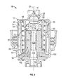
- FIG. 2 , 3 , 4 and 5 schematically illustrate a pump assembly 10 in accordance with a first embodiment of the present invention generally adapted to be used as the pump assembly 10 shown in Figure 1 .
- the pump assembly 10 comprises three principle elements, a piston chamber-forming body 12, a piston-forming element or piston 14 comprising a piston sleeve member 100 and a piston slide member 120 and a one-way inlet valve 16.
- the body 12 carries an outer annular flange 13 with internal threads 15 which are adapted to engage threads of the neck 58 of a bottle 60 shown in dashed lines only in Figure 2 which is to form the fluid reservoir.
- the body 12 includes an interior center tube 17 which provides a cylindrical chamber 18 which has a chamber wall 21, an inner end 22 and an outer end 26.
- An inlet 34 to the chamber 18 is provided in the inner end 22 of the chamber 18 as an outlet of an inlet tube 35 extending inwardly from the inner end 22 of the chamber 18 to an inner end 36 in communication with the bottle 60.
- a flange 37 extends across the inlet tube 35 having a central opening 38 and a plurality of inlet openings 39 therethrough.
- the one-way valve 16 is disposed across the inlet openings 39.
- the inlet openings 39 provide communication through the flange 37 with fluid in the bottle 60.
- the one-way valve 16 permits fluid flow from the bottle 60 into the chamber 18 but prevents fluid flow from the chamber 18 to the bottle 60.
- the one-way valve 16 comprises a shouldered button 40 which is secured in snap- fit relation inside the central opening 38 in the flange 37 with a circular resilient flexing disc 41 extending radially from the button 40.
- the flexing disc 41 is sized to circumferentially abut a cylindrical wall 42 of the inlet tube 35 substantially preventing fluid flow there past from the chamber 18 to the bottle 60.
- the flexing disc 41 is deflectable away from the wall 42 to permit flow from the bottle 60 through the inlet tube 35 into the chamber 18.
- the piston 14 is axially slidably received in the chamber 18 for reciprocal sliding motion inward and outwardly therein.
- the piston 14 is generally circular in cross-section about a central longitudinal axis 23 through the piston.
- the piston 14 comprises two relatively slidable elements, namely an outer piston portion being the sleeve member 100 and an inner piston portion being the slide member 120.
- the sleeve member 100 has a hollow sleeve stem 101 with a sleeve stem wall 102 about a central coaxially bore 103 of the sleeve member 100 and open at an inner end 104 and at an outlet 76 at an outer end 105.
- the sleeve member 100 carries an outer disc 73 which extends radially outwardly from the sleeve stem 101 proximate the inner end 104 of the sleeve member 100.
- the outer disc 73 is a circular disc.
- the outer disc 73 extends radially outwardly on the sleeve stem 101 to circumferentially engage the chamber wall 21.
- the outer disc 73 is sized to circumferentially abut the chamber wall 21 to substantially prevent fluid flow therebetween outwardly.
- the outer disc 73 is biased radially outwardly and carries resilient edge portion with a radially outwardly directed surface for engagement with the chamber wall 21 of the chamber 18 to prevent fluid flow therepast.
- the outer disc 73 is generally frustoconical with an axially inwardly and radially inwardly directed inner cam surface 99.
- the outer disc 73 engages the chamber wall 21 to prevent flow there past both inwardly and outwardly.
- the sleeve member 100 is slidably received in the chamber 18 of the body 12 for reciprocal axial inward and outward movement therein in a stroke of movement between a fully extended position shown in Figure 2 and the fully retracted position shown in Figure 4 .
- the sleeve member 100 In movement of the sleeve member 100 in a retraction stroke between the extended position of Figure 2 and the retracted position of Figure 4 , the sleeve member 100 assumes the intermediate position shown in Figure 3 . In movement of the sleeve member 100 in an extension stroke between the retracted position of Figure 4 and the extended position of Figure 2 , the sleeve member 100 assumes the intermediate position shown in Figure 5 .
- the slide member 120 has a hollow slide stem 121 with a slide stem wall 122 about a central passage 123 closed at an inner end 125 and open at an outer end 124 forming a slide outlet 176.
- the slide member 120 carries two discs which extend radially outwardly from the slide stem, namely, an inner disc 71 and a spreader disc 130.
- the spreader disc 130 is located on the slide member 120 spaced axially outwardly from the inner disc 71.
- the inner disc 71 is a circular resilient flexing disc located proximate an inner end 72 of the slide member 120 and extending radially therefrom.
- the inner disc 71 extends radially outwardly on the stem 70 to circumferentially engage the chamber wall 21.
- the inner disc 71 is sized to circumferentially abut the chamber wall 21 to substantially prevent fluid flow therebetween inwardly.
- the inner disc 71 is biased radially outwardly, however, is adapted to be deflected radially inwardly so as to permit fluid flow past the inner disc 71 outwardly.
- a channel 81 extends radially from an inlet located on the side of the slide stem 121 between the inner disc 71 and the spreader disc 130 inwardly through the slide stem 121 into communication with the central passage 123.
- the channel 81 and central passage 123 permit fluid communication through the slide member 120 to the slide outlet 176 of the slide member 120.
- An outer circular engagement flange 77 is provided outwardly from the outer disc 73 on an outermost end portion of the sleeve stem 101 which extends radially outwardly from the outer end 26 of the chamber 18.
- the flange 77 may be engaged by an actuating device, such as the lever 188 in Figure 1 , in order to move the sleeve member 100 in and out of the body 12.
- Axially extending webs or ribs (not shown) and radially extending circular flanges (not shown) may be provided to extend radially from the sleeve stem 101 to assist in maintaining the sleeve member 100 in axially centred and aligned arrangement when sliding into and out of the chamber 18.
- the slide member 120 is coupled to the sleeve member 100 with the slide stem 121 received in the sleeve bore 103 and the spreading disc 130 of the slide member 120 in the chamber 18 axially inwardly of the outer disc 73.
- the slide member 120 is coaxially slidably coupled to the sleeve member 100 for limited coaxial sliding relative the sleeve member 100 between an extension condition shown in Figures 2 and 5 and a retraction condition shown in Figures 3 and 4 .
- the sleeve stem 101 carries as part of an inner surface of the sleeve stem wall 102, an axially inwardly directed inner stop shoulder 106 inwardly of a first ring portion 107 of the sleeve stem wall 102 of a diameter larger than a diameter of a second outer portion 108 of the sleeve stem wall 102 outward from the ring portion 107.
- the ring portion 107 carries an axially outwardly directed outer stop shoulder 109 between the first ring portion 107 and the second outer portion 108.
- the slide member 120 carries outwardly of the spreader disc 130 as part of the outer surface of the slide stem wall 122 an axially outwardly directed inner stopping shoulder 126 on the spreader disc 130 between the spreader disc 130 and an annular groove portion 128 of the slide stem wall 122 of a diameter smaller than a diameter of the spreader disc 130.
- the slide stem 121 carries an axially inwardly directed outer stopping shoulder 129 between the groove portion 128 of the slide stem wall 122 and an outer portion 130 of the slide stem wall 122 outwardly of the groove portion 128 and of a greater diameter than the groove portion 128.
- the outer end 124 of the passage 123 of the slide stem 121 of the slide member 130 opens into the bore 103 of the sleeve stem 101 of the sleeve member 100 such that together the passage 123 and the bore 103 provide a passageway from the channel 81 to the outlet 76.
- the ring portion 107 of the sleeve stem 101 forms a radially inwardly extending annular ring between the inner stop shoulder 106 and the outer stop shoulder 109.
- the groove portion 128 of the slide stem 121 provides a radially outwardly extending annular slotway between the inner stopping shoulder 126 and the outer stopping shoulder 129.
- the groove portion 128 has an axial extent greater than the axial extent of the ring portion 107.
- the outer stop shoulder 109 engages the outer stopping shoulder 129 to limit sliding of the slide member 120 axially inwardly relative the sleeve member 100 in the extension condition seen in Figures 2 and 5 .
- the inner stop shoulder 106 engages the inner stopping shoulder 126 to limit sliding of the slide member 120 outwardly relative to the sleeve member 100 in the retraction condition seen in Figures 3 and 4 .
- the spreader disc 130 has a radially outwardly and axially outwardly directed camming surface 131 which, when the slide member 120 is urged axially outwardly relative the sleeve member 100 will engage the inner cam surface 99 of the outer disc 73 and urge the outer disc 73 radially outwardly into engagement with the side wall 21 of the chamber 18.
- the axial position of the slide member 120 relative the sleeve member 100 determines the extent to which the spreader disc 130 may engage the outer disc 73 and urge the outer disc 73 into engagement with the chamber wall 21.
- the spreader disc 130 does not engage the outer disc 73 and the tendency of the outer disc 73 to form a seal with the chamber wall 21 and prevent fluid flow therepast will be a function of the extent to which the outer disc 73 engages the chamber wall 21 and, for example, the inherent bias of the outer disc 73 outwardly into the chamber wall 21.
- the principal function of the outer disc 73 in a retraction stroke is to prevent fluid under pressure in the chamber 18 inward of the outer disc 73 from passing between the edge portion of the outer disc 73 outwardly.
- the engagement between the outer disc 73 and the chamber wall 21 is the greatest to prevent undesired fluid flow between the outer disc 73 and the chamber wall 21.
- the inner disc 71 In a withdrawal stroke, the inner disc 71 by its engagement with the chamber wall 21 serves to create a vacuum between the inner disc 71 and the one-way valve 16 to draw fluid in the reservoir, with outward movement of the slide member 120, past the one-way valve 16 into the chamber 18 between the one-way valve 16 and the inner disc 71.
- a withdrawal stroke once the slide member 120 assumes the extension condition, fluid in the chamber 18 captured between the inner disc 71 and the outer disc 73 is moved outwardly without a need for the engagement of the outer disc 73 with the chamber wall 21 to overcome any significant pressure differential.
- fluid in the chamber 18 In a retraction stroke, fluid in the chamber 18 is pressurized between the one-way valve 16 and the inner disc 71.
- the slide stem 121 is coaxially slidable in the bore 103 of the sleeve member 100 and provides a lost motion link between the slide member 120 and the sleeve member 100.
- Other mechanical arrangements may provide the same lost motion link.
- a cycle of operation is now described in which the sleeve member 100 is moved from the extended position of Figure 2 to the intermediate position of Figure 3 and then to the retracted position of Figure 4 in a fluid discharging retraction stroke; and then from the retracted position of Figure 4 to the intermediate position of Figure 5 and then to the extended position of Figure 2 in a fluid charging extension stroke.
- the extension stroke and the retraction stroke together comprise a complete cycle of operation.
- the sleeve member 100 moves outwardly relative the slide member 130 from the retraction condition to the extension condition.
- the outer disc 73 engages the chamber wall 21 of the chamber 18 so as to prevent fluid flow inwardly therepast.
- a vacuum is created within the chamber 18 inwardly of the outer disc 73 between the outer disc 73 and the inner disc 71. This vacuum will tend to draw fluid inwardly from the outlet 76 via the bore 103 and passage 123 and the channel 81 into the chamber 18.
- This vacuum within the chamber 18 will also be applied to the inner disc 71 and if the inner disc 71 disengages from the side wall 21, this vacuum will be applied to the one-way valve 16 and will attempt to deflect the flexing disc 41 of the one-way valve 16 to draw fluid into the chamber 18 from the reservoir 60. Having regard to the nature of the fluid, the resistance of fluid to flow through the outlet 76, the bore 103, the passage 123 and the channel 81 and the size and resiliency of the first disc 71 and the flexing disc 41, the vacuum created in the chamber 18 will draw fluid back from the outlet 76 and/or draw fluid from the reservoir.
- the flexing disc 41 is biased into the wall 42 of the inlet tube 35 such that with relative outward sliding of the sleeve member 100 relative the slide member 120 in the extension stroke, the vacuum within the chamber 18 will not be sufficient to open the one-way valve 16 to permit fluid flow therepast outwardly into the chamber 18 and, as a result, there will be drawback of fluid from the outlet 76.
- the activating lever 188 is biased so as to urge the piston 14 to assume the extended position under the bias of the spring 102 as shown in dashed lines in Figure 1 .
- biasing of the piston 14 toward the fully extended position can be accommodated by a coil spring 50 disposed between the body 12 and the sleeve member 100 coaxially about the axis 23 and biasing the sleeve member 100 outwardly from the body 12.
- the body 12 includes an outer tube 51 having a stop flange 52 at its outer end.
- An annular cavity 53 is defined between the outer tube 51 and inner tube 17.
- the sleeve member 100 includes a guide tube 54 open at an inner end 53 and carrying annular flanges 56 and 57 to engage the inner surface 58 of the outer tube 51 of the body 12 to assist in coaxially locating the sleeve member 100 within the body 12.
- the outermost flange 57 serves as a stop flange to engage the stop flange 52 on the outer tube 51 of the body 12 to prevent the sleeve member 100 from being moved outwardly from the body 12 beyond the fully extended position.
- the coil spring 50 is disposed in the annular cavity 53 in between the guide tube 54 of the sleeve member 100 and the inner tube 17 of the body 12.
- the body 12 preferably is a unitary element formed entirely of plastic preferably by injection molding.
- the sleeve member 100 is illustrated as being made from two elements, namely a center element 140 and a skirt element 142 each preferably by injection molded foam plastic and then secured together.
- Figure 6 shows a second embodiment of a pump assembly 10 in accordance with the present invention.
- the second embodiment shown in Figure 6 is identical to the first embodiment as illustrated in Figure 2 with the exception that the one-way valve arrangement illustrated in Figure 1 and characterized by the shoulder button 40 carrying the flexing disc 41 has been replaced by a one-way valve 16 providing a separate stepped piston arrangement.
- the inlet tube 35 has been extended inwardly and provides a separate chamber 218 within which the flexing disc 41 is coaxially slidably received and with the flexing disc 41 carried on an inward extension 219 of the slide stem 121.
- Figure 7 illustrates a third embodiment of a pump assembly 10 in accordance with the present invention.
- the third embodiment of Figure 7 is substantially identical to the first embodiment as shown in Figure 2 , however, with modification as to the lost link mechanism by which the slide body 120 is coaxially slidable relative to the sleeve member 100 for limited axial sliding.
- the sleeve member 100 includes about its bore 103 an axial inward extension tube 300 which has an enlarged flange 301 at its inner end providing an axially outwardly directed stopping shoulder 106.
- the slide member 120 is provided with its passage 123 to be of a diameter to receive the flange 301 of the extension tube 300 coaxially therein with the slide member 120 having at its outer end a radially inwardly directed flange 302 carrying an inwardly directed stop surface 126 to engage the stopping surface 106 on the sleeve member 100 and limit relative inward sliding of the slide member 120 in the extension condition as shown in Figure 7 . From the extension condition shown in Figure 7 , the slide member 120 can be slid axially outwardly relative to the sleeve member 100 to a retraction condition in which the spreader disc 130 engages the outer disc 73.
- a channel 81 is shown in Figure 7 as extending through the slide stem 122 and axially inwardly such that in all relative positions of the slide member 120 and the sleeve member 100, communication is provided from the channel 81 and passage 123 to the bore 103 of the sleeve member 100 such that fluid may flow to the outlet 76.
- Figure 8 shows a fourth embodiment of a pump assembly 10 in accordance with the present invention which is identical to the third embodiment shown in Figure 7 , however, in which a one-way valve mechanism of the type illustrated in Figure 6 is coupled to the slide member 120.
- axial extending guide vanes 220 are provided on the extension 219 of the slide member 120 which extends into the inlet tube 35 as can be advantageous to maintain the slide body coaxially aligned within the chamber 18.
- a pump in accordance with the present invention may be used either with bottles which are vented or bottles which are not vented.
- Various venting arrangements can be provided so as to relieve any vacuum which may be created within the bottle 60.
- the bottle 60 may be configured, for example, as being a bag or the like which is readily adapted for collapsing.
- a pump in accordance with the present invention is preferably adapted for use in an arrangement as illustrated in Figure 1 in which the bottle 60 is disposed above the chamber 18 having its open end opening downwardly. However, this is not necessary.
- the arrangement in Figure 1 could be inverted and fluid provided to the inlet tube 35 via a dip tube or the bottle 60 may be collapsible.
- sleeve member 100 be in a retracted position as seen in Figure 5 with the slide member 120 in a retraction condition.
- a suitable removable storage cap (not shown) may hold the piston 14 in such a condition coupled to a fluid filled reservoir.
- an activation mechanism can be configured to hold the piston 14 between cycles of operation to resist leaking with the sleeve member 100 in a retracted position and slide member 120 in a retraction condition.
- FIG. 9 illustrates a fifth embodiment of the pump assembly 10 in accordance with the present invention coupled to a sealed bottle 60 and with the pump held in a closed retracted position by a removable cap 400.
- the pump assembly 10 of Figure 9 is substantially identical to that illustrated in Figures 2 to 5 , however, without an internal spring such as spring 50 shown in Figure 4 and with the innermost end 72 of the slide member 120 adapted to extend upwardly into the inlet tube 35 as an annular ring 402 which carries a frustoconical camming surface 404to engage the disc 41 of the one-way valve 16 and urge the disc 41 outwardly into engagement with the wall 42 of the inlet tube 35.
- the cap 400 is shown as carrying a central button 406 on an end wall 107 adapted to be engaged in the outlet 76 of the piston slide member 120 and with the cap 400 to have an annular side wall 408 which engages with the piston chamber-forming body 12 in a snap relation by reason of an annular shoulder 410 carried on the body 12 being engaged in a complementary snap groove 412 on the cap 400.
- Figure 9 schematically illustrates the bottle 60 as sitting on its base 414 and filled with fluid 416.
- the spreader disc 130 engages the outer disc 73 to urge it outwardly to form a good seal with the chamber wall 21 and, as well, the camming surface 404 of the ring 402 engages the disc 41 of the one-way valve 16 to urge it outwardly and form a seal.
- the arrangement illustrated in Figure 9 provides an advantageous configuration for storage in which fluid flow inwardly to or outwardly from the bottle 60 is substantially prevented.
Landscapes
- Engineering & Computer Science (AREA)
- Health & Medical Sciences (AREA)
- Public Health (AREA)
- Mechanical Engineering (AREA)
- General Engineering & Computer Science (AREA)
- Containers And Packaging Bodies Having A Special Means To Remove Contents (AREA)
- Reciprocating Pumps (AREA)
- Details Of Reciprocating Pumps (AREA)
Applications Claiming Priority (1)
| Application Number | Priority Date | Filing Date | Title |
|---|---|---|---|
| CA2772507A CA2772507C (fr) | 2012-03-20 | 2012-03-20 | Pompe precontrainte adaptable |
Publications (3)
| Publication Number | Publication Date |
|---|---|
| EP2641521A2 true EP2641521A2 (fr) | 2013-09-25 |
| EP2641521A3 EP2641521A3 (fr) | 2016-12-07 |
| EP2641521B1 EP2641521B1 (fr) | 2018-05-09 |
Family
ID=47901834
Family Applications (1)
| Application Number | Title | Priority Date | Filing Date |
|---|---|---|---|
| EP13160073.6A Active EP2641521B1 (fr) | 2012-03-20 | 2013-03-20 | Pompe de précharge adaptative |
Country Status (3)
| Country | Link |
|---|---|
| US (1) | US8919611B2 (fr) |
| EP (1) | EP2641521B1 (fr) |
| CA (1) | CA2772507C (fr) |
Cited By (1)
| Publication number | Priority date | Publication date | Assignee | Title |
|---|---|---|---|---|
| WO2018031930A1 (fr) * | 2016-08-12 | 2018-02-15 | Ecolab Usa Inc. | Buse rétractable destiné au dosage ou à la distribution de matériaux à viscosité élevée |
Families Citing this family (14)
| Publication number | Priority date | Publication date | Assignee | Title |
|---|---|---|---|---|
| US20140001211A1 (en) * | 2012-06-08 | 2014-01-02 | Sean Thomas | Mouthwash Dispenser |
| CA2841279C (fr) | 2014-01-29 | 2021-11-23 | Heiner Ophardt | Pompe a mousse a chambre d'air multiple |
| US10259625B2 (en) * | 2014-02-18 | 2019-04-16 | Michael Reckley | Cold shot serving apparatus |
| CA2848857C (fr) | 2014-04-11 | 2022-10-18 | Op-Hygiene Ip Gmbh | Pompe permettant de maintenir la pression interne dans un contenant |
| CA2866055A1 (fr) | 2014-08-29 | 2016-02-29 | Op-Hygiene Ip Gmbh | Pompe volumetrique |
| KR102199145B1 (ko) * | 2015-03-10 | 2021-01-06 | 가부시키가이샤 이와키 | 용적 펌프 |
| US10022023B2 (en) | 2015-04-07 | 2018-07-17 | Vi-Jon, Inc. | Dispenser assembly |
| US10823161B2 (en) * | 2015-05-12 | 2020-11-03 | Gregory L. Indruk | Foam pump and dispenser employing same |
| US10359031B2 (en) * | 2015-05-12 | 2019-07-23 | Gregory L. Indruk | Foam pump and dispenser employing same |
| CA2902754C (fr) | 2015-09-01 | 2023-04-11 | Op-Hygiene Ip Gmbh | Distributeur de nettoyant a mains liquide sous forme de pulverisation et de liquide |
| CA2902751C (fr) | 2015-09-01 | 2022-10-18 | Op-Hygiene Ip Gmbh | Coupure assistee a l'air d'un flux de fluide |
| US10188241B2 (en) | 2016-05-27 | 2019-01-29 | Vi-Jon, Inc. | Dispenser assembly |
| US9700181B1 (en) * | 2016-08-31 | 2017-07-11 | Vi-Jon, Inc. | Dispenser assembly including enclosure with handle |
| FR3077222B1 (fr) * | 2018-01-26 | 2023-12-01 | Aptar France Sas | Distributeur de produit fluide |
Citations (1)
| Publication number | Priority date | Publication date | Assignee | Title |
|---|---|---|---|---|
| US5975360A (en) | 1991-05-20 | 1999-11-02 | Ophardt; Heiner | Capped piston pump |
Family Cites Families (21)
| Publication number | Priority date | Publication date | Assignee | Title |
|---|---|---|---|---|
| US6446840B2 (en) | 2000-05-18 | 2002-09-10 | Ophardt Product Kg | Apparatus for making and dispensing foam |
| CA2341659C (fr) | 2001-03-20 | 2007-08-07 | Hygiene-Technik Inc. | Distributeur de liquide pour la distribution de mousse |
| US6557736B1 (en) | 2002-01-18 | 2003-05-06 | Heiner Ophardt | Pivoting piston head for pump |
| US7198175B2 (en) * | 2002-04-26 | 2007-04-03 | Heiner Ophardt | Manual or pump assist fluid dispenser |
| CA2464905C (fr) * | 2004-03-19 | 2008-12-23 | Hygiene-Technik Inc. | Distributeur a deux composants |
| CA2470532C (fr) * | 2004-06-09 | 2008-11-18 | Hygiene-Technik Inc. | Pompe a mouvement de rappel |
| CA2504989C (fr) | 2005-04-22 | 2013-03-12 | Gotohti.Com Inc. | Pompe de distribution de mousse etagee |
| US7770874B2 (en) | 2005-04-22 | 2010-08-10 | Gotohii.com Inc. | Foam pump with spring |
| CA2547044C (fr) | 2005-05-19 | 2014-08-12 | Gotohti.Com Inc. | Pompe a piston separable |
| US7337930B2 (en) | 2005-05-20 | 2008-03-04 | Gotohti.Com Inc. | Foaming pump with improved air inlet valve |
| CA2513181C (fr) * | 2005-07-25 | 2012-03-13 | Gotohti.Com Inc. | Generateur a mousse antibacterienne |
| CA2545905A1 (fr) | 2006-05-05 | 2007-11-05 | Gotohti.Com Inc. | Pompe a piston a cylindre etage |
| CA2549972C (fr) | 2006-06-13 | 2013-11-12 | Gotohti.Com Inc. | Guide tubulaire porte-piston |
| CA2591046A1 (fr) | 2007-06-08 | 2008-12-08 | Gotohti.Com Inc. | Mecanisme casse-vide pour soupapes a piston |
| CA2613785C (fr) | 2007-12-07 | 2015-03-24 | Gotohti.Com Inc. | Distributeur de mousse a fente inclinee |
| CA2634981C (fr) | 2008-06-12 | 2016-08-09 | Gotohti.Com Inc. | Pompe a piston a dechargement par retrait |
| US8157134B2 (en) | 2008-12-05 | 2012-04-17 | Gotohti.Com Inc. | Piston with guide rings |
| CA2672057C (fr) * | 2009-07-14 | 2017-07-11 | Gotohti.Com Inc. | Pompe a retropoussee |
| CA2687879C (fr) | 2009-12-08 | 2016-11-01 | Gotohti.Com Inc. | Piston dote d'une butee frangible |
| CA2698915C (fr) | 2010-04-01 | 2017-06-27 | Gotohti.Com Inc. | Pompe a tige stationnaire |
| CA2719635C (fr) | 2010-11-01 | 2017-10-31 | Gotohti.Com Inc. | Piston telescopique pour pompe |
-
2012
- 2012-03-20 CA CA2772507A patent/CA2772507C/fr active Active
-
2013
- 2013-03-11 US US13/794,361 patent/US8919611B2/en active Active
- 2013-03-20 EP EP13160073.6A patent/EP2641521B1/fr active Active
Patent Citations (1)
| Publication number | Priority date | Publication date | Assignee | Title |
|---|---|---|---|---|
| US5975360A (en) | 1991-05-20 | 1999-11-02 | Ophardt; Heiner | Capped piston pump |
Cited By (2)
| Publication number | Priority date | Publication date | Assignee | Title |
|---|---|---|---|---|
| WO2018031930A1 (fr) * | 2016-08-12 | 2018-02-15 | Ecolab Usa Inc. | Buse rétractable destiné au dosage ou à la distribution de matériaux à viscosité élevée |
| US10376917B2 (en) | 2016-08-12 | 2019-08-13 | Ecolab Usa Inc. | Retractable nozzle for dosing or dispensing high viscosity materials |
Also Published As
| Publication number | Publication date |
|---|---|
| US20140091106A1 (en) | 2014-04-03 |
| EP2641521A3 (fr) | 2016-12-07 |
| EP2641521B1 (fr) | 2018-05-09 |
| US8919611B2 (en) | 2014-12-30 |
| CA2772507A1 (fr) | 2013-09-20 |
| CA2772507C (fr) | 2018-12-18 |
Similar Documents
| Publication | Publication Date | Title |
|---|---|---|
| EP2641521B1 (fr) | Pompe de précharge adaptative | |
| US5401148A (en) | Manually operated reciprocating liquid pump | |
| CA2149313C (fr) | Pompe a liquide, en plastique et jetable | |
| US8944294B2 (en) | Stationary stem pump | |
| US8056772B2 (en) | Vacuum release mechanism | |
| US3362344A (en) | Liquid dispenser | |
| US20130126639A1 (en) | Perfume Atomizer | |
| US3044413A (en) | Pump pistons | |
| US9731890B2 (en) | Pump maintaining container internal pressure | |
| US20070257064A1 (en) | Stepped cylinder piston pump | |
| WO1985004852A1 (fr) | Pompe de distribution de liquide a partir d'un conteneur | |
| KR20010049439A (ko) | 방아쇠 분사기용 배출 밸브 조립체 | |
| US9062667B2 (en) | Variable volume bore piston pump | |
| US8500416B2 (en) | Doubled seal disk for piston pump | |
| JP2010504852A (ja) | 液体ディスペンサ装置 | |
| US11084052B2 (en) | Stationary outlet stem pump | |
| EP2785466B1 (fr) | Dispositif de pompage pour un récipient de fluide |
Legal Events
| Date | Code | Title | Description |
|---|---|---|---|
| PUAI | Public reference made under article 153(3) epc to a published international application that has entered the european phase |
Free format text: ORIGINAL CODE: 0009012 |
|
| AK | Designated contracting states |
Kind code of ref document: A2 Designated state(s): AL AT BE BG CH CY CZ DE DK EE ES FI FR GB GR HR HU IE IS IT LI LT LU LV MC MK MT NL NO PL PT RO RS SE SI SK SM TR |
|
| AX | Request for extension of the european patent |
Extension state: BA ME |
|
| PUAL | Search report despatched |
Free format text: ORIGINAL CODE: 0009013 |
|
| AK | Designated contracting states |
Kind code of ref document: A3 Designated state(s): AL AT BE BG CH CY CZ DE DK EE ES FI FR GB GR HR HU IE IS IT LI LT LU LV MC MK MT NL NO PL PT RO RS SE SI SK SM TR |
|
| AX | Request for extension of the european patent |
Extension state: BA ME |
|
| RIC1 | Information provided on ipc code assigned before grant |
Ipc: B05B 11/00 20060101ALI20161102BHEP Ipc: A47K 5/12 20060101AFI20161102BHEP |
|
| STAA | Information on the status of an ep patent application or granted ep patent |
Free format text: STATUS: REQUEST FOR EXAMINATION WAS MADE |
|
| 17P | Request for examination filed |
Effective date: 20170607 |
|
| RBV | Designated contracting states (corrected) |
Designated state(s): AL AT BE BG CH CY CZ DE DK EE ES FI FR GB GR HR HU IE IS IT LI LT LU LV MC MK MT NL NO PL PT RO RS SE SI SK SM TR |
|
| GRAJ | Information related to disapproval of communication of intention to grant by the applicant or resumption of examination proceedings by the epo deleted |
Free format text: ORIGINAL CODE: EPIDOSDIGR1 |
|
| STAA | Information on the status of an ep patent application or granted ep patent |
Free format text: STATUS: GRANT OF PATENT IS INTENDED |
|
| GRAP | Despatch of communication of intention to grant a patent |
Free format text: ORIGINAL CODE: EPIDOSNIGR1 |
|
| INTG | Intention to grant announced |
Effective date: 20171025 |
|
| GRAS | Grant fee paid |
Free format text: ORIGINAL CODE: EPIDOSNIGR3 |
|
| GRAA | (expected) grant |
Free format text: ORIGINAL CODE: 0009210 |
|
| STAA | Information on the status of an ep patent application or granted ep patent |
Free format text: STATUS: THE PATENT HAS BEEN GRANTED |
|
| AK | Designated contracting states |
Kind code of ref document: B1 Designated state(s): AL AT BE BG CH CY CZ DE DK EE ES FI FR GB GR HR HU IE IS IT LI LT LU LV MC MK MT NL NO PL PT RO RS SE SI SK SM TR |
|
| REG | Reference to a national code |
Ref country code: GB Ref legal event code: FG4D |
|
| REG | Reference to a national code |
Ref country code: CH Ref legal event code: EP Ref country code: AT Ref legal event code: REF Ref document number: 996745 Country of ref document: AT Kind code of ref document: T Effective date: 20180515 |
|
| REG | Reference to a national code |
Ref country code: IE Ref legal event code: FG4D |
|
| REG | Reference to a national code |
Ref country code: DE Ref legal event code: R096 Ref document number: 602013037141 Country of ref document: DE |
|
| REG | Reference to a national code |
Ref country code: NL Ref legal event code: MP Effective date: 20180509 |
|
| REG | Reference to a national code |
Ref country code: LT Ref legal event code: MG4D |
|
| PG25 | Lapsed in a contracting state [announced via postgrant information from national office to epo] |
Ref country code: SE Free format text: LAPSE BECAUSE OF FAILURE TO SUBMIT A TRANSLATION OF THE DESCRIPTION OR TO PAY THE FEE WITHIN THE PRESCRIBED TIME-LIMIT Effective date: 20180509 Ref country code: ES Free format text: LAPSE BECAUSE OF FAILURE TO SUBMIT A TRANSLATION OF THE DESCRIPTION OR TO PAY THE FEE WITHIN THE PRESCRIBED TIME-LIMIT Effective date: 20180509 Ref country code: LT Free format text: LAPSE BECAUSE OF FAILURE TO SUBMIT A TRANSLATION OF THE DESCRIPTION OR TO PAY THE FEE WITHIN THE PRESCRIBED TIME-LIMIT Effective date: 20180509 Ref country code: NO Free format text: LAPSE BECAUSE OF FAILURE TO SUBMIT A TRANSLATION OF THE DESCRIPTION OR TO PAY THE FEE WITHIN THE PRESCRIBED TIME-LIMIT Effective date: 20180809 Ref country code: BG Free format text: LAPSE BECAUSE OF FAILURE TO SUBMIT A TRANSLATION OF THE DESCRIPTION OR TO PAY THE FEE WITHIN THE PRESCRIBED TIME-LIMIT Effective date: 20180809 Ref country code: FI Free format text: LAPSE BECAUSE OF FAILURE TO SUBMIT A TRANSLATION OF THE DESCRIPTION OR TO PAY THE FEE WITHIN THE PRESCRIBED TIME-LIMIT Effective date: 20180509 |
|
| PG25 | Lapsed in a contracting state [announced via postgrant information from national office to epo] |
Ref country code: GR Free format text: LAPSE BECAUSE OF FAILURE TO SUBMIT A TRANSLATION OF THE DESCRIPTION OR TO PAY THE FEE WITHIN THE PRESCRIBED TIME-LIMIT Effective date: 20180810 Ref country code: HR Free format text: LAPSE BECAUSE OF FAILURE TO SUBMIT A TRANSLATION OF THE DESCRIPTION OR TO PAY THE FEE WITHIN THE PRESCRIBED TIME-LIMIT Effective date: 20180509 Ref country code: NL Free format text: LAPSE BECAUSE OF FAILURE TO SUBMIT A TRANSLATION OF THE DESCRIPTION OR TO PAY THE FEE WITHIN THE PRESCRIBED TIME-LIMIT Effective date: 20180509 Ref country code: RS Free format text: LAPSE BECAUSE OF FAILURE TO SUBMIT A TRANSLATION OF THE DESCRIPTION OR TO PAY THE FEE WITHIN THE PRESCRIBED TIME-LIMIT Effective date: 20180509 Ref country code: LV Free format text: LAPSE BECAUSE OF FAILURE TO SUBMIT A TRANSLATION OF THE DESCRIPTION OR TO PAY THE FEE WITHIN THE PRESCRIBED TIME-LIMIT Effective date: 20180509 |
|
| REG | Reference to a national code |
Ref country code: AT Ref legal event code: MK05 Ref document number: 996745 Country of ref document: AT Kind code of ref document: T Effective date: 20180509 |
|
| PG25 | Lapsed in a contracting state [announced via postgrant information from national office to epo] |
Ref country code: AT Free format text: LAPSE BECAUSE OF FAILURE TO SUBMIT A TRANSLATION OF THE DESCRIPTION OR TO PAY THE FEE WITHIN THE PRESCRIBED TIME-LIMIT Effective date: 20180509 Ref country code: DK Free format text: LAPSE BECAUSE OF FAILURE TO SUBMIT A TRANSLATION OF THE DESCRIPTION OR TO PAY THE FEE WITHIN THE PRESCRIBED TIME-LIMIT Effective date: 20180509 Ref country code: EE Free format text: LAPSE BECAUSE OF FAILURE TO SUBMIT A TRANSLATION OF THE DESCRIPTION OR TO PAY THE FEE WITHIN THE PRESCRIBED TIME-LIMIT Effective date: 20180509 Ref country code: SK Free format text: LAPSE BECAUSE OF FAILURE TO SUBMIT A TRANSLATION OF THE DESCRIPTION OR TO PAY THE FEE WITHIN THE PRESCRIBED TIME-LIMIT Effective date: 20180509 Ref country code: RO Free format text: LAPSE BECAUSE OF FAILURE TO SUBMIT A TRANSLATION OF THE DESCRIPTION OR TO PAY THE FEE WITHIN THE PRESCRIBED TIME-LIMIT Effective date: 20180509 Ref country code: CZ Free format text: LAPSE BECAUSE OF FAILURE TO SUBMIT A TRANSLATION OF THE DESCRIPTION OR TO PAY THE FEE WITHIN THE PRESCRIBED TIME-LIMIT Effective date: 20180509 Ref country code: PL Free format text: LAPSE BECAUSE OF FAILURE TO SUBMIT A TRANSLATION OF THE DESCRIPTION OR TO PAY THE FEE WITHIN THE PRESCRIBED TIME-LIMIT Effective date: 20180509 |
|
| REG | Reference to a national code |
Ref country code: DE Ref legal event code: R097 Ref document number: 602013037141 Country of ref document: DE |
|
| PG25 | Lapsed in a contracting state [announced via postgrant information from national office to epo] |
Ref country code: IT Free format text: LAPSE BECAUSE OF FAILURE TO SUBMIT A TRANSLATION OF THE DESCRIPTION OR TO PAY THE FEE WITHIN THE PRESCRIBED TIME-LIMIT Effective date: 20180509 Ref country code: SM Free format text: LAPSE BECAUSE OF FAILURE TO SUBMIT A TRANSLATION OF THE DESCRIPTION OR TO PAY THE FEE WITHIN THE PRESCRIBED TIME-LIMIT Effective date: 20180509 |
|
| PLBE | No opposition filed within time limit |
Free format text: ORIGINAL CODE: 0009261 |
|
| STAA | Information on the status of an ep patent application or granted ep patent |
Free format text: STATUS: NO OPPOSITION FILED WITHIN TIME LIMIT |
|
| 26N | No opposition filed |
Effective date: 20190212 |
|
| PG25 | Lapsed in a contracting state [announced via postgrant information from national office to epo] |
Ref country code: SI Free format text: LAPSE BECAUSE OF FAILURE TO SUBMIT A TRANSLATION OF THE DESCRIPTION OR TO PAY THE FEE WITHIN THE PRESCRIBED TIME-LIMIT Effective date: 20180509 |
|
| PG25 | Lapsed in a contracting state [announced via postgrant information from national office to epo] |
Ref country code: MC Free format text: LAPSE BECAUSE OF FAILURE TO SUBMIT A TRANSLATION OF THE DESCRIPTION OR TO PAY THE FEE WITHIN THE PRESCRIBED TIME-LIMIT Effective date: 20180509 |
|
| REG | Reference to a national code |
Ref country code: CH Ref legal event code: PL |
|
| PG25 | Lapsed in a contracting state [announced via postgrant information from national office to epo] |
Ref country code: LU Free format text: LAPSE BECAUSE OF NON-PAYMENT OF DUE FEES Effective date: 20190320 Ref country code: AL Free format text: LAPSE BECAUSE OF FAILURE TO SUBMIT A TRANSLATION OF THE DESCRIPTION OR TO PAY THE FEE WITHIN THE PRESCRIBED TIME-LIMIT Effective date: 20180509 |
|
| REG | Reference to a national code |
Ref country code: BE Ref legal event code: MM Effective date: 20190331 |
|
| PG25 | Lapsed in a contracting state [announced via postgrant information from national office to epo] |
Ref country code: CH Free format text: LAPSE BECAUSE OF NON-PAYMENT OF DUE FEES Effective date: 20190331 Ref country code: LI Free format text: LAPSE BECAUSE OF NON-PAYMENT OF DUE FEES Effective date: 20190331 Ref country code: IE Free format text: LAPSE BECAUSE OF NON-PAYMENT OF DUE FEES Effective date: 20190320 |
|
| PG25 | Lapsed in a contracting state [announced via postgrant information from national office to epo] |
Ref country code: BE Free format text: LAPSE BECAUSE OF NON-PAYMENT OF DUE FEES Effective date: 20190331 |
|
| PG25 | Lapsed in a contracting state [announced via postgrant information from national office to epo] |
Ref country code: TR Free format text: LAPSE BECAUSE OF FAILURE TO SUBMIT A TRANSLATION OF THE DESCRIPTION OR TO PAY THE FEE WITHIN THE PRESCRIBED TIME-LIMIT Effective date: 20180509 |
|
| PG25 | Lapsed in a contracting state [announced via postgrant information from national office to epo] |
Ref country code: MT Free format text: LAPSE BECAUSE OF NON-PAYMENT OF DUE FEES Effective date: 20190320 Ref country code: PT Free format text: LAPSE BECAUSE OF FAILURE TO SUBMIT A TRANSLATION OF THE DESCRIPTION OR TO PAY THE FEE WITHIN THE PRESCRIBED TIME-LIMIT Effective date: 20180910 |
|
| PG25 | Lapsed in a contracting state [announced via postgrant information from national office to epo] |
Ref country code: CY Free format text: LAPSE BECAUSE OF FAILURE TO SUBMIT A TRANSLATION OF THE DESCRIPTION OR TO PAY THE FEE WITHIN THE PRESCRIBED TIME-LIMIT Effective date: 20180509 |
|
| PG25 | Lapsed in a contracting state [announced via postgrant information from national office to epo] |
Ref country code: IS Free format text: LAPSE BECAUSE OF FAILURE TO SUBMIT A TRANSLATION OF THE DESCRIPTION OR TO PAY THE FEE WITHIN THE PRESCRIBED TIME-LIMIT Effective date: 20180909 |
|
| PG25 | Lapsed in a contracting state [announced via postgrant information from national office to epo] |
Ref country code: HU Free format text: LAPSE BECAUSE OF FAILURE TO SUBMIT A TRANSLATION OF THE DESCRIPTION OR TO PAY THE FEE WITHIN THE PRESCRIBED TIME-LIMIT; INVALID AB INITIO Effective date: 20130320 |
|
| PG25 | Lapsed in a contracting state [announced via postgrant information from national office to epo] |
Ref country code: MK Free format text: LAPSE BECAUSE OF FAILURE TO SUBMIT A TRANSLATION OF THE DESCRIPTION OR TO PAY THE FEE WITHIN THE PRESCRIBED TIME-LIMIT Effective date: 20180509 |
|
| PGFP | Annual fee paid to national office [announced via postgrant information from national office to epo] |
Ref country code: DE Payment date: 20240327 Year of fee payment: 12 Ref country code: GB Payment date: 20240320 Year of fee payment: 12 |
|
| PGFP | Annual fee paid to national office [announced via postgrant information from national office to epo] |
Ref country code: FR Payment date: 20240321 Year of fee payment: 12 |