EP2641482A1 - Machine for making tobacco industry products - Google Patents
Machine for making tobacco industry products Download PDFInfo
- Publication number
- EP2641482A1 EP2641482A1 EP13159343.6A EP13159343A EP2641482A1 EP 2641482 A1 EP2641482 A1 EP 2641482A1 EP 13159343 A EP13159343 A EP 13159343A EP 2641482 A1 EP2641482 A1 EP 2641482A1
- Authority
- EP
- European Patent Office
- Prior art keywords
- tubular structure
- source
- machine according
- conduit
- machine
- Prior art date
- Legal status (The legal status is an assumption and is not a legal conclusion. Google has not performed a legal analysis and makes no representation as to the accuracy of the status listed.)
- Granted
Links
- 241000208125 Nicotiana Species 0.000 title claims abstract description 9
- 235000002637 Nicotiana tabacum Nutrition 0.000 title claims abstract description 9
- 235000019504 cigarettes Nutrition 0.000 description 10
- 208000032820 Ring chromosome 13 syndrome Diseases 0.000 description 6
- 239000012530 fluid Substances 0.000 description 4
- 235000019505 tobacco product Nutrition 0.000 description 3
- 230000001419 dependent effect Effects 0.000 description 1
- 238000009826 distribution Methods 0.000 description 1
- 230000000694 effects Effects 0.000 description 1
- 238000005265 energy consumption Methods 0.000 description 1
- 238000001914 filtration Methods 0.000 description 1
- 238000012856 packing Methods 0.000 description 1
- 238000005192 partition Methods 0.000 description 1
- 230000009257 reactivity Effects 0.000 description 1
- 238000009827 uniform distribution Methods 0.000 description 1
Images


Classifications
-
- A—HUMAN NECESSITIES
- A24—TOBACCO; CIGARS; CIGARETTES; SIMULATED SMOKING DEVICES; SMOKERS' REQUISITES
- A24C—MACHINES FOR MAKING CIGARS OR CIGARETTES
- A24C5/00—Making cigarettes; Making tipping materials for, or attaching filters or mouthpieces to, cigars or cigarettes
Definitions
- This invention relates to a machine for making tobacco industry products.
- tobacco industry products is used to denote, for example, cigarettes, filter-tipped cigarettes, cigarette filters of any kind, in particular, filters composed of two or more segments, cigarette packets, whether hard or soft, cigarette packages and other products similar to these.
- Figure 1 schematically illustrates in its entirety a prior art making machine, denoted by the numeral 100, comprising a base having a vertical wall which supports a plurality of operating elements 101.
- the operating elements 101 are, for the most part, rotary drums which revolve about horizontal axes of rotation and which are mounted on the vertical supporting wall.
- the rotary drums are provided with a plurality of suction cavities for receiving and withholding the tobacco products during processing.
- Every making machine 100 also comprises an air suction system 103 for the rotary drums and designed to generate a predetermined negative pressure at the respective suction cavities.
- the suction system 103 of prior art making machines 100 comprises an air suction source 102 and a main manifold 105 extending along the machine 100 and in fluid communication with the source 102.
- the rotary drums 101 are connected to respective compartments 104 formed internally of the base and connected to the main manifold 105 through flow openings 106.
- compartments 104 are delimited by the vertical wall supporting the rotary drums 101 and by internal partition sectors, defining large spaces within the base, as illustrated in Figure 2 .
- the air suction source 102 In use, the air suction source 102 generates a predetermined negative pressure inside the main manifold 105 and, through the flow openings 106, inside each of the compartments 104, so that the rotary drums 101 connected to the compartments 104 are subject to the negative pressure generated inside the selfsame compartments 104.
- the suction system 103 described above is referred to technically as a "comb system” in that it has a main section, that is, the main manifold 105, which branches into successive use locations, that is, the compartments 104.
- the distribution of the air suction flow rates is not uniform since the air suction flow tends to be weaker at the use locations or compartments 104 which are furthest away from the source 102.
- the source 102 increases the air flow rate in the entire system, even where not needed.
- the suction system 103 is inefficient in terms of energy consumption and not reactive in responding to transients in that it is slow to restore normal operating conditions since emptying out the compartments 104 takes a long time and a lot of energy from the source 102.
- turbulence may be created inside the compartments 104 which reduces the efficiency of the suction system 103.
- This invention has for an aim to provide a machine for making tobacco products which overcomes the above mentioned disadvantages.
- the aim of this invention is to provide a machine for making tobacco products which comprises a suction system which allows uniform distribution of air suction flow rates to the use locations and which reacts quickly to transients and restores the machine to normal operating conditions.
- the numeral 1 schematically indicates a machine for making tobacco industry products which comprises a base 2 having a vertical front wall 3 and a vertical rear wall 9 facing the vertical front wall 3.
- the making machine 1 comprises a plurality of operating elements 4 supported by the vertical front wall 3.
- the operating elements 4 are rotary drums 5, each revolving about a respective axis of rotation which is substantially horizontal relative to the vertical wall 3.
- the machine 1 comprises an air suction system 6 comprising at least one suction source 7. More specifically, the source 7 generates a predetermined negative pressure as a function of the working conditions of the operating elements 4.
- the suction system 6 comprises a single source 7 capable of serving the entire system 6.
- the suction system 6 comprises a tubular structure 8 which connects the source 7 directly to the operating elements 4.
- tubular structure 8 of the suction system 6 is defined by a plurality of conduits 10,14 which branch off from the source 7 towards the operating elements 4 placing the latter in direct fluid communication with the source 7 itself.
- the tubular structure 8 allows the space occupied by the suction system 6 in the base 2 to be significantly reduced since the large empty spaces constituted by the aforementioned compartments are no longer necessary.
- the conduits 10,14 of the tubular structure 8 have a substantially rectangular cross section.
- tubular structure 8 means a structure made as a single component designed to be installed inside the base 2 of the machine 1.
- the single component is interposed between the vertical front wall 3 and the vertical rear wall 9.
- the tubular structure 8 is ring-shaped and is formed by a main conduit 10 having two inlet openings 11 in communication with the source 7.
- the tubular structure 8 comprises a main ring 12 and at least one secondary ring 13. In the embodiment described, there are four secondary rings 13.
- the main ring 12 is formed by the main conduit 10 and each secondary ring 13 is formed by at least one secondary conduit 14 extending from the source 7 and in fluid communication with the main conduit 10.
- Each secondary ring 13 is thus formed by at least one secondary conduit 14 and by at least part of the main conduit 10.
- each secondary conduit 14 has an inlet opening 15 in communication with the source 7 and a connecting opening 16 in communication with the main conduit 10. Consequently, the secondary conduits 14 of each secondary ring 13 are connected to the main conduit 10.
- the secondary conduits 14 of the tubular structure 8 also place the main conduit 10 in direct communication with the source 7 through the connecting openings 16.
- the configuration of the tubular structure 8 is defined both by the main conduit 10 and by the arrangement of the secondary conduits 14. More specifically, the main ring 12 and each secondary ring 13 have a substantially polygonal shape having, at their vertices, rounded conduit stretches 17 and, along their sides, straight conduit stretches 18.
- This configuration is substantially dependent on the arrangement of the operating elements 4 on the vertical front wall 3 of the machine 1, in order for the operating elements 4 to be connected directly to the source 7.
- the tubular structure 8 comprises a plurality of branches 19 connecting the operating elements 4.
- the tubular structure 8 has a corresponding fitting 19a for connecting the respective operating element 4.
- the main conduit 10 comprises a plurality of branches 19 disposed one after the other along the tubular structure 8, and each secondary conduit 14 comprises at least one branch 19.
- the branches 19 have respective outlet openings 20 at which they are connected directly to the operating elements 4 through the fittings 19a.
- the branches 19 are located along the straight conduit stretches 18 because they are not subject to the concentrated load losses which occur at the rounded conduit stretches 17.
- each straight conduit stretch 18 of the main conduit 10 has at least two branches 19 and each straight conduit stretch 18 of the respective secondary conduit 14 has one or more branches 19.
- the arrangement of the branches 19 and the configuration of the tubular structure 8 determine a path P along which the air drawn into conduits 10, 14 circulates.
- the air circulating along the path P supplies each operating element 4 through at least two air flow routes formed by at least one secondary conduit 14 and at least part of the main conduit 10.
- the source 7 is capable of generating a predetermined negative pressure in each operating element 4 by causing the air to flow in the main ring 12 and in the secondary rings 13 along the path P.
- the source 7 is simultaneously in communication with the two inlet openings 11 of the main conduit 10 and with the inlet openings 15 of the secondary conduits 14 connected to the main conduit 10 and, therefore, the air feeds the operating elements 4 by way of at least two flow routes.
- the suction system 6 comprises flow regulator means 21 positioned along the tubular structure 8 itself. More specifically, the flow regulator means 21 are positioned both along the main conduit 10 and along the secondary conduits 14, in such a way as to regulate the flow of air drawn into the main ring 12 and into each secondary ring 13.
- the ring shape of the tubular structure 8 of the suction system 6 makes it possible to equally divide the suction flow rates since, as stated above, each operating element 4 is in communication with the source 7 by way of at least two flow routes through the main conduit 10 and the secondary conduits 14. Moreover, the direct communication between the operating elements 4 and the source 7 greatly improves the reactivity of the suction system 6 to transients, that is to say, to conditions of non-equilibrium, allowing normal operating conditions to be restored in a short space of time.
- the connecting conduits 10,14 of the tubular structure 8 are built into the base 2.
- the machine 1 described above is a cigarette making machine, in particular a machine for making filter-tipped cigarettes.
- the machine 1 described above is a machine for making cigarettes filters, in particular filters composed of two or more filtering segments.
- the machine 1 described above is a packing machine for making cigarette packets or groups of cigarette packets.
Landscapes
- Manufacturing Of Cigar And Cigarette Tobacco (AREA)
- Manufacture Of Tobacco Products (AREA)
Abstract
Description
- This invention relates to a machine for making tobacco industry products.
- It should be noted that the term "tobacco industry products" is used to denote, for example, cigarettes, filter-tipped cigarettes, cigarette filters of any kind, in particular, filters composed of two or more segments, cigarette packets, whether hard or soft, cigarette packages and other products similar to these.
-
Figure 1 schematically illustrates in its entirety a prior art making machine, denoted by thenumeral 100, comprising a base having a vertical wall which supports a plurality ofoperating elements 101. Theoperating elements 101 are, for the most part, rotary drums which revolve about horizontal axes of rotation and which are mounted on the vertical supporting wall. - More specifically, the rotary drums are provided with a plurality of suction cavities for receiving and withholding the tobacco products during processing.
- Every making
machine 100 also comprises anair suction system 103 for the rotary drums and designed to generate a predetermined negative pressure at the respective suction cavities. - The
suction system 103 of priorart making machines 100 comprises anair suction source 102 and amain manifold 105 extending along themachine 100 and in fluid communication with thesource 102. Therotary drums 101 are connected torespective compartments 104 formed internally of the base and connected to themain manifold 105 throughflow openings 106. - More specifically, the
compartments 104 are delimited by the vertical wall supporting therotary drums 101 and by internal partition sectors, defining large spaces within the base, as illustrated inFigure 2 . - In use, the
air suction source 102 generates a predetermined negative pressure inside themain manifold 105 and, through theflow openings 106, inside each of thecompartments 104, so that therotary drums 101 connected to thecompartments 104 are subject to the negative pressure generated inside theselfsame compartments 104. - The
suction system 103 described above is referred to technically as a "comb system" in that it has a main section, that is, themain manifold 105, which branches into successive use locations, that is, thecompartments 104. - This constructional solution is not free of disadvantages, however.
- In effect, in the
suction system 103, the distribution of the air suction flow rates is not uniform since the air suction flow tends to be weaker at the use locations orcompartments 104 which are furthest away from thesource 102. - Also, when some use locations are in need of a boost in the air suction flow rate, the
source 102 increases the air flow rate in the entire system, even where not needed. - Further, the
suction system 103 is inefficient in terms of energy consumption and not reactive in responding to transients in that it is slow to restore normal operating conditions since emptying out thecompartments 104 takes a long time and a lot of energy from thesource 102. - Moreover, turbulence may be created inside the
compartments 104 which reduces the efficiency of thesuction system 103. - This invention has for an aim to provide a machine for making tobacco products which overcomes the above mentioned disadvantages.
- More specifically, the aim of this invention is to provide a machine for making tobacco products which comprises a suction system which allows uniform distribution of air suction flow rates to the use locations and which reacts quickly to transients and restores the machine to normal operating conditions.
- The technical purpose indicated and the aims specified are achieved by a machine for making tobacco industry products comprising the technical features set out in the
independent claim 1. - The invention is described below with reference to the accompanying drawings, which illustrate a non-limiting embodiment of it, and in which:
-
Figure 1 is a schematic front view of a prior art machine for making tobacco industry products; -
Figure 2 is a perspective view of a detail fromFigure 1 ; -
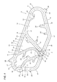
Figure 3 is a perspective view of a suction system of a machine for making tobacco industry products according to this invention; -
Figure 4 is schematic front view of the suction system ofFigure 3 . - With reference to
Figures 3 and4 , thenumeral 1 schematically indicates a machine for making tobacco industry products which comprises abase 2 having avertical front wall 3 and a vertical rear wall 9 facing thevertical front wall 3. - The making
machine 1 comprises a plurality ofoperating elements 4 supported by thevertical front wall 3. - The
operating elements 4 arerotary drums 5, each revolving about a respective axis of rotation which is substantially horizontal relative to thevertical wall 3. - The
machine 1 comprises anair suction system 6 comprising at least onesuction source 7. More specifically, thesource 7 generates a predetermined negative pressure as a function of the working conditions of theoperating elements 4. - Preferably, the
suction system 6 comprises asingle source 7 capable of serving theentire system 6. - More specifically, the
suction system 6 comprises atubular structure 8 which connects thesource 7 directly to theoperating elements 4. - Unlike the prior art, the
tubular structure 8 of thesuction system 6 is defined by a plurality ofconduits source 7 towards theoperating elements 4 placing the latter in direct fluid communication with thesource 7 itself. - The
tubular structure 8 allows the space occupied by thesuction system 6 in thebase 2 to be significantly reduced since the large empty spaces constituted by the aforementioned compartments are no longer necessary. - Preferably, the
conduits tubular structure 8 have a substantially rectangular cross section. - Advantageously,
tubular structure 8 means a structure made as a single component designed to be installed inside thebase 2 of themachine 1. - More specifically, again by way of example, the single component is interposed between the
vertical front wall 3 and the vertical rear wall 9. - The
tubular structure 8 is ring-shaped and is formed by amain conduit 10 having twoinlet openings 11 in communication with thesource 7. - The
tubular structure 8 comprises amain ring 12 and at least onesecondary ring 13. In the embodiment described, there are foursecondary rings 13. - The
main ring 12 is formed by themain conduit 10 and eachsecondary ring 13 is formed by at least onesecondary conduit 14 extending from thesource 7 and in fluid communication with themain conduit 10. - Each
secondary ring 13 is thus formed by at least onesecondary conduit 14 and by at least part of themain conduit 10. - More specifically, each
secondary conduit 14 has an inlet opening 15 in communication with thesource 7 and a connecting opening 16 in communication with themain conduit 10. Consequently, thesecondary conduits 14 of eachsecondary ring 13 are connected to themain conduit 10. - That means the
secondary conduits 14 of thetubular structure 8 also place themain conduit 10 in direct communication with thesource 7 through the connectingopenings 16. - The configuration of the
tubular structure 8 is defined both by themain conduit 10 and by the arrangement of thesecondary conduits 14. More specifically, themain ring 12 and eachsecondary ring 13 have a substantially polygonal shape having, at their vertices, rounded conduit stretches 17 and, along their sides, straight conduit stretches 18. - This configuration is substantially dependent on the arrangement of the
operating elements 4 on thevertical front wall 3 of themachine 1, in order for theoperating elements 4 to be connected directly to thesource 7. - In order to place the
operating elements 4 in fluid communication with thesource 7, thetubular structure 8 comprises a plurality ofbranches 19 connecting theoperating elements 4. - More specifically, at each
branch 19, thetubular structure 8 has acorresponding fitting 19a for connecting therespective operating element 4. - More specifically, the
main conduit 10 comprises a plurality ofbranches 19 disposed one after the other along thetubular structure 8, and eachsecondary conduit 14 comprises at least onebranch 19. Thebranches 19 haverespective outlet openings 20 at which they are connected directly to theoperating elements 4 through thefittings 19a. - Preferably, the
branches 19 are located along the straight conduit stretches 18 because they are not subject to the concentrated load losses which occur at the rounded conduit stretches 17. - In the embodiment described, each
straight conduit stretch 18 of themain conduit 10 has at least twobranches 19 and eachstraight conduit stretch 18 of the respectivesecondary conduit 14 has one ormore branches 19. - The arrangement of the
branches 19 and the configuration of thetubular structure 8 determine a path P along which the air drawn intoconduits - As illustrated in
Figure 4 , the air circulating along the path P supplies eachoperating element 4 through at least two air flow routes formed by at least onesecondary conduit 14 and at least part of themain conduit 10. - In other words, the
source 7 is capable of generating a predetermined negative pressure in eachoperating element 4 by causing the air to flow in themain ring 12 and in thesecondary rings 13 along the path P. - This is possible because the
source 7 is simultaneously in communication with the twoinlet openings 11 of themain conduit 10 and with theinlet openings 15 of thesecondary conduits 14 connected to themain conduit 10 and, therefore, the air feeds theoperating elements 4 by way of at least two flow routes. - In order to regulate the suction air flow generated by the
source 7 and circulating in thetubular structure 8, thesuction system 6 comprises flow regulator means 21 positioned along thetubular structure 8 itself. More specifically, the flow regulator means 21 are positioned both along themain conduit 10 and along thesecondary conduits 14, in such a way as to regulate the flow of air drawn into themain ring 12 and into eachsecondary ring 13. - Advantageously, the ring shape of the
tubular structure 8 of thesuction system 6 makes it possible to equally divide the suction flow rates since, as stated above, eachoperating element 4 is in communication with thesource 7 by way of at least two flow routes through themain conduit 10 and thesecondary conduits 14. Moreover, the direct communication between theoperating elements 4 and thesource 7 greatly improves the reactivity of thesuction system 6 to transients, that is to say, to conditions of non-equilibrium, allowing normal operating conditions to be restored in a short space of time. - In an alternative embodiment, the connecting
conduits tubular structure 8 are built into thebase 2. - In a first embodiment, the
machine 1 described above is a cigarette making machine, in particular a machine for making filter-tipped cigarettes. - In a different embodiment, the
machine 1 described above is a machine for making cigarettes filters, in particular filters composed of two or more filtering segments. - In a further embodiment, the
machine 1 described above is a packing machine for making cigarette packets or groups of cigarette packets.
Claims (10)
- A machine for making tobacco industry products comprising a base (2) having a vertical front wall (3), a plurality of operating elements (4) supported by the vertical front wall (3) and an air suction system (6) comprising at least one suction source (7), characterized in that the suction system (6) comprises a tubular structure (8) directly connecting the source (7) to at least one operating element (4).
- The machine according to claim 1, characterized in that the tubular structure (8) comprises at least one conduit (10, 14) directly connecting the source (7) to at least one operating element (4).
- The machine according to claim 2, characterized in that tubular structure (8) is ring-shaped and comprises a main conduit (10) having two inlet openings (11) in communication with the source (7); the operating elements (4) being directly connected to the source (7) through the main conduit (10).
- The machine according to any one of claims 1 to 3, characterized in that the tubular structure (8) comprises a main ring (12) and at least one secondary ring (13); the main ring (12) being formed by the main conduit (10) and the secondary ring (13) being formed by at least one secondary conduit (14) and by at least part of the main conduit (10); the secondary conduit (14) having an inlet opening (15) in communication with the suction source (7) and a connecting opening (16) in communication with the main conduit (10).
- The machine according to any one of claims 1 to 4, characterized in that the configuration of the tubular structure (8) depends on the position of the operating elements (4) on the vertical front wall (3) of the machine (1), the configuration of the tubular structure (8) determining a path (P) of the air drawn inside the main and secondary conduits (10, 14) of the tubular structure (8).
- The machine according to claim 5, characterized in that the tubular structure (8) comprises a plurality of branches (19) connecting the operating elements (4).
- The machine according to any one of claims 1 to 6, characterized in that the tubular structure (8) feeds each operating element (4) through at least two routes for flow of the air along the path (P), the routes for flow of the air being formed by secondary conduits (14) and by at least part of the main conduit (10).
- The machine according to any one of the preceding claims, characterized in that the suction system (6) comprises air flow regulator means (21) positioned along the tubular structure (8).
- The machine according to any one of the preceding claims, characterized in that the tubular structure (8) is made from a single component inserted inside the base (2) and interposed between the vertical front wall (3) and the vertical rear wall (9).
- The machine according to any one of the preceding claims, characterized in that the conduits (10, 14) of the tubular structure (8) have a substantially rectangular cross-section.
Priority Applications (1)
| Application Number | Priority Date | Filing Date | Title |
|---|---|---|---|
| PL13159343T PL2641482T3 (en) | 2012-03-22 | 2013-03-15 | Machine for making tobacco industry products |
Applications Claiming Priority (1)
| Application Number | Priority Date | Filing Date | Title |
|---|---|---|---|
| IT000154A ITBO20120154A1 (en) | 2012-03-22 | 2012-03-22 | PACKAGING MACHINE FOR PRODUCTS OF THE TOBACCO INDUSTRY. |
Publications (2)
| Publication Number | Publication Date |
|---|---|
| EP2641482A1 true EP2641482A1 (en) | 2013-09-25 |
| EP2641482B1 EP2641482B1 (en) | 2016-11-23 |
Family
ID=46548551
Family Applications (1)
| Application Number | Title | Priority Date | Filing Date |
|---|---|---|---|
| EP13159343.6A Not-in-force EP2641482B1 (en) | 2012-03-22 | 2013-03-15 | Machine for making tobacco industry products |
Country Status (4)
| Country | Link |
|---|---|
| EP (1) | EP2641482B1 (en) |
| CN (1) | CN103315388B (en) |
| IT (1) | ITBO20120154A1 (en) |
| PL (1) | PL2641482T3 (en) |
Citations (5)
| Publication number | Priority date | Publication date | Assignee | Title |
|---|---|---|---|---|
| DE3213393A1 (en) * | 1981-04-25 | 1982-11-11 | Hauni-Werke Körber & Co KG, 2050 Hamburg | Conveying apparatus for articles in the tobacco processing industry |
| DE3236732A1 (en) * | 1981-12-03 | 1983-06-09 | VEB Wissenschaft und Technik Tabakindustrie im VEB Kombinat Tabak Berlin, DDR 8021 Dresden | Central suctioning of apparatuses for cigarette strand formation |
| GB2173389A (en) * | 1985-04-10 | 1986-10-15 | Gd Spa | Suction system for cigarette machines |
| EP0290756A1 (en) * | 1987-05-15 | 1988-11-17 | SASIB S.p.A. | Method and device for controlling the vacuum in a succession of suction conveyors |
| DE102008020631B3 (en) * | 2008-04-24 | 2009-08-20 | Hauni Maschinenbau Ag | Method for operating a machine of the tobacco processing industry and corresponding machine |
Family Cites Families (3)
| Publication number | Priority date | Publication date | Assignee | Title |
|---|---|---|---|---|
| US4452255A (en) * | 1981-04-25 | 1984-06-05 | Hauni-Werke Korber & Co. Kg. | Apparatus for transporting and classifying discrete articles of the tobacco processing industry |
| DE102005033504A1 (en) * | 2005-07-14 | 2007-01-18 | Hauni Maschinenbau Ag | Device for transporting rod-shaped articles of the tobacco-processing industry |
| DE102009015501B4 (en) * | 2009-04-02 | 2011-03-31 | Hauni Maschinenbau Ag | Vacuum supply to a machine of the tobacco processing industry |
-
2012
- 2012-03-22 IT IT000154A patent/ITBO20120154A1/en unknown
-
2013
- 2013-03-15 PL PL13159343T patent/PL2641482T3/en unknown
- 2013-03-15 CN CN201310163008.5A patent/CN103315388B/en not_active Expired - Fee Related
- 2013-03-15 EP EP13159343.6A patent/EP2641482B1/en not_active Not-in-force
Patent Citations (5)
| Publication number | Priority date | Publication date | Assignee | Title |
|---|---|---|---|---|
| DE3213393A1 (en) * | 1981-04-25 | 1982-11-11 | Hauni-Werke Körber & Co KG, 2050 Hamburg | Conveying apparatus for articles in the tobacco processing industry |
| DE3236732A1 (en) * | 1981-12-03 | 1983-06-09 | VEB Wissenschaft und Technik Tabakindustrie im VEB Kombinat Tabak Berlin, DDR 8021 Dresden | Central suctioning of apparatuses for cigarette strand formation |
| GB2173389A (en) * | 1985-04-10 | 1986-10-15 | Gd Spa | Suction system for cigarette machines |
| EP0290756A1 (en) * | 1987-05-15 | 1988-11-17 | SASIB S.p.A. | Method and device for controlling the vacuum in a succession of suction conveyors |
| DE102008020631B3 (en) * | 2008-04-24 | 2009-08-20 | Hauni Maschinenbau Ag | Method for operating a machine of the tobacco processing industry and corresponding machine |
Non-Patent Citations (1)
| Title |
|---|
| "SYSTEM FOR REGULATING THE SUPPLY OF AIR TO INDIVIDUAL UNITS OF A MACHINE", RESEARCH DISCLOSURE, MASON PUBLICATIONS, HAMPSHIRE, GB, no. 311, 1 March 1990 (1990-03-01), pages 212/213, XP000104487, ISSN: 0374-4353 * |
Also Published As
| Publication number | Publication date |
|---|---|
| ITBO20120154A1 (en) | 2013-09-23 |
| EP2641482B1 (en) | 2016-11-23 |
| CN103315388B (en) | 2016-08-10 |
| CN103315388A (en) | 2013-09-25 |
| PL2641482T3 (en) | 2017-06-30 |
Similar Documents
| Publication | Publication Date | Title |
|---|---|---|
| GB2511989A (en) | Cyclonic separating apparatus | |
| EP4159252A3 (en) | Apparatus for filtering | |
| AR049808A1 (en) | TOBERA ASSEMBLY FOR A PRODUCT DISTRIBUTION SYSTEM AS REQUESTED | |
| MX2015002516A (en) | An apparatus for packaging dosed quantities of solid drug portions. | |
| CN204750673U (en) | Food package conveyor | |
| WO2012110136A1 (en) | Cutting machine with increased productivity for manufacturing wire-like rods, particularly for the production of rod-like electrodes for welding | |
| WO2016131071A3 (en) | Filter device and filter method | |
| JP2011234717A (en) | Conveyor for conveying rod-shaped product from magazine to conveying path in tobacco-processing industry, and conveying method | |
| EP2641482B1 (en) | Machine for making tobacco industry products | |
| CN108438327A (en) | The conveying material arranging apparatus of rod shaped materials | |
| CN103040107A (en) | Transfer drum for a machine for producing products for the tobacco manufacturing industry | |
| JP6803142B2 (en) | Methods and equipment for inserting directional objects into filter rods | |
| CN107244447B (en) | A direct push type automatic packing device for electromechanical parts of welding machine | |
| MX2012008508A (en) | Device for dispensing a plurality of unitary doses of dry powder, and inhaler comprising such device. | |
| WO2013057112A3 (en) | Feed unit | |
| EP3024341B1 (en) | Method and member for guiding a strand of filter fibers and filter rod making machine | |
| IT202000023959A1 (en) | METHOD OF CONTROLLING A FEEDING UNIT FOR FEEDING COMPONENTS FOR SMOKING ITEMS AND DRUM CONVEYOR OF A FEEDING UNIT FOR FEEDING COMPONENTS FOR SMOKING ITEMS | |
| CN103523302B (en) | A kind of rice dumpling automatic tray mounting box production line | |
| CN115279190B (en) | Production of three-dimensional products from bulk pumpable fiber food material | |
| JP2018038806A (en) | Peristaltic pump with modular case | |
| CN203558266U (en) | Automatic supporting box loading production line for glue puddings | |
| CN203332409U (en) | Buffering and storing and liquid distributing integrated device | |
| CN222592852U (en) | A raw material feeding system | |
| SE1751475A1 (en) | A filtering apparatus for separating liquid from a slurry | |
| ITMI20111351A1 (en) | OBJECT ORIENTATION DEVICE |
Legal Events
| Date | Code | Title | Description |
|---|---|---|---|
| PUAI | Public reference made under article 153(3) epc to a published international application that has entered the european phase |
Free format text: ORIGINAL CODE: 0009012 |
|
| AK | Designated contracting states |
Kind code of ref document: A1 Designated state(s): AL AT BE BG CH CY CZ DE DK EE ES FI FR GB GR HR HU IE IS IT LI LT LU LV MC MK MT NL NO PL PT RO RS SE SI SK SM TR |
|
| AX | Request for extension of the european patent |
Extension state: BA ME |
|
| 17P | Request for examination filed |
Effective date: 20140321 |
|
| RBV | Designated contracting states (corrected) |
Designated state(s): AL AT BE BG CH CY CZ DE DK EE ES FI FR GB GR HR HU IE IS IT LI LT LU LV MC MK MT NL NO PL PT RO RS SE SI SK SM TR |
|
| GRAP | Despatch of communication of intention to grant a patent |
Free format text: ORIGINAL CODE: EPIDOSNIGR1 |
|
| INTG | Intention to grant announced |
Effective date: 20160624 |
|
| GRAS | Grant fee paid |
Free format text: ORIGINAL CODE: EPIDOSNIGR3 |
|
| GRAA | (expected) grant |
Free format text: ORIGINAL CODE: 0009210 |
|
| AK | Designated contracting states |
Kind code of ref document: B1 Designated state(s): AL AT BE BG CH CY CZ DE DK EE ES FI FR GB GR HR HU IE IS IT LI LT LU LV MC MK MT NL NO PL PT RO RS SE SI SK SM TR |
|
| REG | Reference to a national code |
Ref country code: GB Ref legal event code: FG4D |
|
| REG | Reference to a national code |
Ref country code: CH Ref legal event code: EP |
|
| REG | Reference to a national code |
Ref country code: IE Ref legal event code: FG4D |
|
| REG | Reference to a national code |
Ref country code: AT Ref legal event code: REF Ref document number: 847028 Country of ref document: AT Kind code of ref document: T Effective date: 20161215 |
|
| REG | Reference to a national code |
Ref country code: DE Ref legal event code: R096 Ref document number: 602013014305 Country of ref document: DE |
|
| PG25 | Lapsed in a contracting state [announced via postgrant information from national office to epo] |
Ref country code: LV Free format text: LAPSE BECAUSE OF FAILURE TO SUBMIT A TRANSLATION OF THE DESCRIPTION OR TO PAY THE FEE WITHIN THE PRESCRIBED TIME-LIMIT Effective date: 20161123 |
|
| REG | Reference to a national code |
Ref country code: LT Ref legal event code: MG4D Ref country code: FR Ref legal event code: PLFP Year of fee payment: 5 |
|
| REG | Reference to a national code |
Ref country code: NL Ref legal event code: MP Effective date: 20161123 |
|
| REG | Reference to a national code |
Ref country code: AT Ref legal event code: MK05 Ref document number: 847028 Country of ref document: AT Kind code of ref document: T Effective date: 20161123 |
|
| PG25 | Lapsed in a contracting state [announced via postgrant information from national office to epo] |
Ref country code: NO Free format text: LAPSE BECAUSE OF FAILURE TO SUBMIT A TRANSLATION OF THE DESCRIPTION OR TO PAY THE FEE WITHIN THE PRESCRIBED TIME-LIMIT Effective date: 20170223 Ref country code: GR Free format text: LAPSE BECAUSE OF FAILURE TO SUBMIT A TRANSLATION OF THE DESCRIPTION OR TO PAY THE FEE WITHIN THE PRESCRIBED TIME-LIMIT Effective date: 20170224 Ref country code: NL Free format text: LAPSE BECAUSE OF FAILURE TO SUBMIT A TRANSLATION OF THE DESCRIPTION OR TO PAY THE FEE WITHIN THE PRESCRIBED TIME-LIMIT Effective date: 20161123 Ref country code: LT Free format text: LAPSE BECAUSE OF FAILURE TO SUBMIT A TRANSLATION OF THE DESCRIPTION OR TO PAY THE FEE WITHIN THE PRESCRIBED TIME-LIMIT Effective date: 20161123 Ref country code: SE Free format text: LAPSE BECAUSE OF FAILURE TO SUBMIT A TRANSLATION OF THE DESCRIPTION OR TO PAY THE FEE WITHIN THE PRESCRIBED TIME-LIMIT Effective date: 20161123 |
|
| PGFP | Annual fee paid to national office [announced via postgrant information from national office to epo] |
Ref country code: FR Payment date: 20170327 Year of fee payment: 5 |
|
| PG25 | Lapsed in a contracting state [announced via postgrant information from national office to epo] |
Ref country code: FI Free format text: LAPSE BECAUSE OF FAILURE TO SUBMIT A TRANSLATION OF THE DESCRIPTION OR TO PAY THE FEE WITHIN THE PRESCRIBED TIME-LIMIT Effective date: 20161123 Ref country code: RS Free format text: LAPSE BECAUSE OF FAILURE TO SUBMIT A TRANSLATION OF THE DESCRIPTION OR TO PAY THE FEE WITHIN THE PRESCRIBED TIME-LIMIT Effective date: 20161123 Ref country code: AT Free format text: LAPSE BECAUSE OF FAILURE TO SUBMIT A TRANSLATION OF THE DESCRIPTION OR TO PAY THE FEE WITHIN THE PRESCRIBED TIME-LIMIT Effective date: 20161123 Ref country code: ES Free format text: LAPSE BECAUSE OF FAILURE TO SUBMIT A TRANSLATION OF THE DESCRIPTION OR TO PAY THE FEE WITHIN THE PRESCRIBED TIME-LIMIT Effective date: 20161123 Ref country code: HR Free format text: LAPSE BECAUSE OF FAILURE TO SUBMIT A TRANSLATION OF THE DESCRIPTION OR TO PAY THE FEE WITHIN THE PRESCRIBED TIME-LIMIT Effective date: 20161123 Ref country code: PT Free format text: LAPSE BECAUSE OF FAILURE TO SUBMIT A TRANSLATION OF THE DESCRIPTION OR TO PAY THE FEE WITHIN THE PRESCRIBED TIME-LIMIT Effective date: 20170323 |
|
| PG25 | Lapsed in a contracting state [announced via postgrant information from national office to epo] |
Ref country code: DK Free format text: LAPSE BECAUSE OF FAILURE TO SUBMIT A TRANSLATION OF THE DESCRIPTION OR TO PAY THE FEE WITHIN THE PRESCRIBED TIME-LIMIT Effective date: 20161123 Ref country code: EE Free format text: LAPSE BECAUSE OF FAILURE TO SUBMIT A TRANSLATION OF THE DESCRIPTION OR TO PAY THE FEE WITHIN THE PRESCRIBED TIME-LIMIT Effective date: 20161123 Ref country code: RO Free format text: LAPSE BECAUSE OF FAILURE TO SUBMIT A TRANSLATION OF THE DESCRIPTION OR TO PAY THE FEE WITHIN THE PRESCRIBED TIME-LIMIT Effective date: 20161123 Ref country code: CZ Free format text: LAPSE BECAUSE OF FAILURE TO SUBMIT A TRANSLATION OF THE DESCRIPTION OR TO PAY THE FEE WITHIN THE PRESCRIBED TIME-LIMIT Effective date: 20161123 Ref country code: SK Free format text: LAPSE BECAUSE OF FAILURE TO SUBMIT A TRANSLATION OF THE DESCRIPTION OR TO PAY THE FEE WITHIN THE PRESCRIBED TIME-LIMIT Effective date: 20161123 |
|
| PGFP | Annual fee paid to national office [announced via postgrant information from national office to epo] |
Ref country code: DE Payment date: 20170329 Year of fee payment: 5 |
|
| REG | Reference to a national code |
Ref country code: DE Ref legal event code: R097 Ref document number: 602013014305 Country of ref document: DE |
|
| PG25 | Lapsed in a contracting state [announced via postgrant information from national office to epo] |
Ref country code: SM Free format text: LAPSE BECAUSE OF FAILURE TO SUBMIT A TRANSLATION OF THE DESCRIPTION OR TO PAY THE FEE WITHIN THE PRESCRIBED TIME-LIMIT Effective date: 20161123 Ref country code: IT Free format text: LAPSE BECAUSE OF FAILURE TO SUBMIT A TRANSLATION OF THE DESCRIPTION OR TO PAY THE FEE WITHIN THE PRESCRIBED TIME-LIMIT Effective date: 20161123 Ref country code: BE Free format text: LAPSE BECAUSE OF FAILURE TO SUBMIT A TRANSLATION OF THE DESCRIPTION OR TO PAY THE FEE WITHIN THE PRESCRIBED TIME-LIMIT Effective date: 20161123 Ref country code: BG Free format text: LAPSE BECAUSE OF FAILURE TO SUBMIT A TRANSLATION OF THE DESCRIPTION OR TO PAY THE FEE WITHIN THE PRESCRIBED TIME-LIMIT Effective date: 20170223 |
|
| PGFP | Annual fee paid to national office [announced via postgrant information from national office to epo] |
Ref country code: PL Payment date: 20170222 Year of fee payment: 5 |
|
| PLBE | No opposition filed within time limit |
Free format text: ORIGINAL CODE: 0009261 |
|
| STAA | Information on the status of an ep patent application or granted ep patent |
Free format text: STATUS: NO OPPOSITION FILED WITHIN TIME LIMIT |
|
| REG | Reference to a national code |
Ref country code: CH Ref legal event code: PL |
|
| 26N | No opposition filed |
Effective date: 20170824 |
|
| GBPC | Gb: european patent ceased through non-payment of renewal fee |
Effective date: 20170315 |
|
| PG25 | Lapsed in a contracting state [announced via postgrant information from national office to epo] |
Ref country code: MC Free format text: LAPSE BECAUSE OF FAILURE TO SUBMIT A TRANSLATION OF THE DESCRIPTION OR TO PAY THE FEE WITHIN THE PRESCRIBED TIME-LIMIT Effective date: 20161123 Ref country code: SI Free format text: LAPSE BECAUSE OF FAILURE TO SUBMIT A TRANSLATION OF THE DESCRIPTION OR TO PAY THE FEE WITHIN THE PRESCRIBED TIME-LIMIT Effective date: 20161123 |
|
| REG | Reference to a national code |
Ref country code: IE Ref legal event code: MM4A |
|
| PG25 | Lapsed in a contracting state [announced via postgrant information from national office to epo] |
Ref country code: LU Free format text: LAPSE BECAUSE OF NON-PAYMENT OF DUE FEES Effective date: 20170315 |
|
| PG25 | Lapsed in a contracting state [announced via postgrant information from national office to epo] |
Ref country code: IE Free format text: LAPSE BECAUSE OF NON-PAYMENT OF DUE FEES Effective date: 20170315 Ref country code: GB Free format text: LAPSE BECAUSE OF NON-PAYMENT OF DUE FEES Effective date: 20170315 Ref country code: LI Free format text: LAPSE BECAUSE OF NON-PAYMENT OF DUE FEES Effective date: 20170331 Ref country code: CH Free format text: LAPSE BECAUSE OF NON-PAYMENT OF DUE FEES Effective date: 20170331 |
|
| PG25 | Lapsed in a contracting state [announced via postgrant information from national office to epo] |
Ref country code: MT Free format text: LAPSE BECAUSE OF NON-PAYMENT OF DUE FEES Effective date: 20170315 |
|
| REG | Reference to a national code |
Ref country code: DE Ref legal event code: R119 Ref document number: 602013014305 Country of ref document: DE |
|
| PG25 | Lapsed in a contracting state [announced via postgrant information from national office to epo] |
Ref country code: DE Free format text: LAPSE BECAUSE OF NON-PAYMENT OF DUE FEES Effective date: 20181002 |
|
| PG25 | Lapsed in a contracting state [announced via postgrant information from national office to epo] |
Ref country code: FR Free format text: LAPSE BECAUSE OF NON-PAYMENT OF DUE FEES Effective date: 20180331 |
|
| PG25 | Lapsed in a contracting state [announced via postgrant information from national office to epo] |
Ref country code: HU Free format text: LAPSE BECAUSE OF FAILURE TO SUBMIT A TRANSLATION OF THE DESCRIPTION OR TO PAY THE FEE WITHIN THE PRESCRIBED TIME-LIMIT; INVALID AB INITIO Effective date: 20130315 |
|
| PG25 | Lapsed in a contracting state [announced via postgrant information from national office to epo] |
Ref country code: CY Free format text: LAPSE BECAUSE OF NON-PAYMENT OF DUE FEES Effective date: 20161123 |
|
| PG25 | Lapsed in a contracting state [announced via postgrant information from national office to epo] |
Ref country code: PL Free format text: LAPSE BECAUSE OF NON-PAYMENT OF DUE FEES Effective date: 20180315 Ref country code: MK Free format text: LAPSE BECAUSE OF FAILURE TO SUBMIT A TRANSLATION OF THE DESCRIPTION OR TO PAY THE FEE WITHIN THE PRESCRIBED TIME-LIMIT Effective date: 20161123 |
|
| PG25 | Lapsed in a contracting state [announced via postgrant information from national office to epo] |
Ref country code: TR Free format text: LAPSE BECAUSE OF FAILURE TO SUBMIT A TRANSLATION OF THE DESCRIPTION OR TO PAY THE FEE WITHIN THE PRESCRIBED TIME-LIMIT Effective date: 20161123 |
|
| PG25 | Lapsed in a contracting state [announced via postgrant information from national office to epo] |
Ref country code: AL Free format text: LAPSE BECAUSE OF FAILURE TO SUBMIT A TRANSLATION OF THE DESCRIPTION OR TO PAY THE FEE WITHIN THE PRESCRIBED TIME-LIMIT Effective date: 20161123 Ref country code: IS Free format text: LAPSE BECAUSE OF FAILURE TO SUBMIT A TRANSLATION OF THE DESCRIPTION OR TO PAY THE FEE WITHIN THE PRESCRIBED TIME-LIMIT Effective date: 20170323 |