EP2640463B1 - Peel-away is-4/df-4 lead implant tool with electrical contacts - Google Patents
Peel-away is-4/df-4 lead implant tool with electrical contacts Download PDFInfo
- Publication number
- EP2640463B1 EP2640463B1 EP11770027.8A EP11770027A EP2640463B1 EP 2640463 B1 EP2640463 B1 EP 2640463B1 EP 11770027 A EP11770027 A EP 11770027A EP 2640463 B1 EP2640463 B1 EP 2640463B1
- Authority
- EP
- European Patent Office
- Prior art keywords
- implant tool
- lead
- sheath
- terminal connector
- pliable sheath
- Prior art date
- Legal status (The legal status is an assumption and is not a legal conclusion. Google has not performed a legal analysis and makes no representation as to the accuracy of the status listed.)
- Active
Links
Images




Classifications
-
- A—HUMAN NECESSITIES
- A61—MEDICAL OR VETERINARY SCIENCE; HYGIENE
- A61N—ELECTROTHERAPY; MAGNETOTHERAPY; RADIATION THERAPY; ULTRASOUND THERAPY
- A61N1/00—Electrotherapy; Circuits therefor
- A61N1/02—Details
- A61N1/04—Electrodes
- A61N1/05—Electrodes for implantation or insertion into the body, e.g. heart electrode
-
- A—HUMAN NECESSITIES
- A61—MEDICAL OR VETERINARY SCIENCE; HYGIENE
- A61N—ELECTROTHERAPY; MAGNETOTHERAPY; RADIATION THERAPY; ULTRASOUND THERAPY
- A61N1/00—Electrotherapy; Circuits therefor
- A61N1/18—Applying electric currents by contact electrodes
- A61N1/32—Applying electric currents by contact electrodes alternating or intermittent currents
- A61N1/36—Applying electric currents by contact electrodes alternating or intermittent currents for stimulation
- A61N1/372—Arrangements in connection with the implantation of stimulators
- A61N1/375—Constructional arrangements, e.g. casings
-
- A—HUMAN NECESSITIES
- A61—MEDICAL OR VETERINARY SCIENCE; HYGIENE
- A61N—ELECTROTHERAPY; MAGNETOTHERAPY; RADIATION THERAPY; ULTRASOUND THERAPY
- A61N1/00—Electrotherapy; Circuits therefor
- A61N1/02—Details
- A61N1/04—Electrodes
- A61N1/05—Electrodes for implantation or insertion into the body, e.g. heart electrode
- A61N1/056—Transvascular endocardial electrode systems
- A61N1/057—Anchoring means; Means for fixing the head inside the heart
- A61N2001/058—Fixing tools
-
- H—ELECTRICITY
- H01—ELECTRIC ELEMENTS
- H01R—ELECTRICALLY-CONDUCTIVE CONNECTIONS; STRUCTURAL ASSOCIATIONS OF A PLURALITY OF MUTUALLY-INSULATED ELECTRICAL CONNECTING ELEMENTS; COUPLING DEVICES; CURRENT COLLECTORS
- H01R2201/00—Connectors or connections adapted for particular applications
- H01R2201/12—Connectors or connections adapted for particular applications for medicine and surgery
Definitions
- the present invention generally relates to implantable medical devices. More particularly, the present invention relates to devices, systems and methods for installing and testing multi-conductor leads within a patient's body.
- CRM cardiac rhythm management
- neurostimulation applications are known.
- leads are frequently delivered intravascularly to an implantation location on or within a patient's heart, typically under the aid of fluoroscopy.
- the lead is coupled to a pulse generator or other implantable device for sensing cardiac electrical activity, delivering therapeutic stimuli, and/or for performing some other desired function within the body.
- Such leads often include a distal electrode end which contacts the heart tissue, and a proximal, terminal end which is connected to the pulse generator.
- the distal electrode end of the lead typically includes one or more features such as an active fixation helix or a number of passive tines to facilitate securing the lead to the heart tissue.
- the terminal end of the lead includes one or more electrical contacts that are electrically connected to the electrodes on the terminal end of the lead via a number of conductors.
- the leads are tested for proper positioning and function as part of the implantation process and prior to being connected to the pulse generator, allowing the implanting physician to evaluate pacing and sensing performance prior to concluding that the particular lead position is suitable.
- a Pacing System Analyzer may be connected to the terminal end of the lead to evaluate the performance of the lead.
- a lead implant tool can be temporarily coupled to the terminal end of the lead, allowing the conductors of the PSA to be connected to the electrical contacts on the terminal end of the lead.
- the implant tool may facilitate the attachment of several alligator clips, plunger cups, or other spring-loaded cups to the electrical contacts on the terminal end of the lead.
- lead implant tools for use in connecting the conductors of a PSA to a multi-conductor lead are described in U.S. Patent Publication No, 2005/0177199 to Hansen et at and U.S. Patent Publication No. 2006/0258193 to Hoecke et al.
- US 2004/230268 A1 relates to a medical lead adapter assembly for facilitating an electrical connection between an implantable medical lead connector and an external medical device.
- the adapter includes a housing, having a sidewall and a longitudinally extending connector receptacle, and at least one contact opening passing through the sidewall to the receptacle.
- the contact opening is positioned in a location corresponding with at least one ring contact of the lead connector, when the lead connector is engaged within the receptacle, and allows electrical connection between at least one contact element of the external medical device and the at least one ring contact of the lead connector.
- US 2004/230268 A1 does not disclose an implant tool comprising a pliable sheath, wherein the pliable sheath comprises at least one tear strip extending from a proximal end to a distal end of the pliable sheath
- the invention relates to an implant tool according to claim 1 and to a lead assembly according to claim 11.
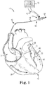
- Fig. 1 is a schematic view showing an illustrative system 10 for implanting and testing an implantable lead 12 within the body of a patient.
- the system 10 is described in conjunction with an implantable lead 12 for use in sensing cardiac electrical activity and/or for providing electrical stimulus therapy to a patient's heart 14.
- the system 10 can be used in other contexts where implantable leads are employed, and where testing is to be conducted prior to the connection of the lead to another implantable device such as a pulse generator.
- the system 10 can be used to aid in the implantation and testing of an implantable neurostimulation lead prior to its connection to another implantable device such as a pulse generator.
- the lead 12 includes a lead body 16 extending from a proximal end 18 adapted to be coupled to a pulse generator to a distal end 22.
- the lead 12 can be implanted in the patient's heart 14, which as shown in FIG. 1 , includes a right atrium 24, a right ventricle 26, a left atrium 28, and a left ventricle 30.
- the distal end 22 of the lead 12 is transvenously guided through the right atrium 24, through the coronary sinus ostium 32, and into a branch of the coronary sinus 36 or great cardiac vein 38.
- the illustrated position of the lead 12 can be used for sensing or for delivering pacing energy to the left side of heart 14, or to treat arrhythmias or other cardiac disorders requiring therapy delivered to the left side of the heart 14. Additionally, in some embodiments, the lead 12 can be configured to provide treatment in other regions of the heart 14 (e.g., the right atrium 24 or right ventricle 26).
- the lead 12 can include one or more electrodes 42 for providing electrical therapy to and/or sensing therapy to the patient's heart 14.
- the implantable lead 12 is a quadripolar lead including four electrodes 42 located in a distal region 44 of the lead 12.
- the system 10 further includes an implant tool 54, a stiffening member such as a stylet or guidewire 56, and a Pacing System Analyzer (PSA) 58 that can be used for implanting and testing the lead 12 within the body.
- a Pacing System Analyzer PSA
- the function and location of the lead 12 can be tested by connecting a terminal connector 60 located at the proximal end 18 of the lead 12 to several electrical conductors 62 of the PSA 58.
- This evaluation can be performed after implantation of the lead 12 at the potential stimulation site.
- Such testing can be performed, for example, to verify that the electrodes 42 are properly positioned on or within the heart 14.
- the PSA 58 can also be used to perform other functions such as measuring pacing thresholds, lead impedance and r-wave amplitude.
- the implant tool 54 can be used with passive fixation leads to enable stylet or guidewire passage and electrical connection while protecting the terminal connector 60.
- other fixation mechanisms such as, for example, a fixation helix, can also be deployed via the implant tool 54.
- the implant tool 54 is configured to permit the implanting physician to easily feed various stylets or guidewires 56 into a pin lumen of the implantable lead 12, to make an electrical connection between the PSA conductors 62 and a terminal pin 64 ( FIG. 2 ) and one or more terminal ring electrodes 66, 68, 70 ( FIG. 2 ) on the lead 12.
- the implant tool 54 can be packaged and shipped already attached to an implantable lead 12.
- the pre-assembled components can then be packaged in a blister pack, pouch, or other suitable storage medium for later use by the implanting physician.
- the implant tool 54 protects the lead terminal connector 60 throughout the implant procedure from electrical clips or other surgical implements.
- the implant tool 54 is configured such that it can remain coupled to the lead connector throughout the implantation and testing procedures, up to the point where the lead can be connected to another implantable device such as a pulse generator.
- the lead implant tool 54 is removed from the lead 12, and the lead 12 is then connected to the pulse generator.
- the lead 12 is configured to convey electrical signals back and forth between the pulse generator and the heart 14.
- the lead 12 can be used to deliver electrical therapeutic stimulus for pacing the heart 14.
- the lead 12 can be utilized to deliver electric shocks to the heart 14 in response to an event such as a heart attack or ventricular tachycardia.
- the pulse generator includes both pacing and defibrillation capabilities, or is capable of performing biventricular or other multi-site resynchronization therapies such as cardiac resynchronization therapy (CRT).
- CRT cardiac resynchronization therapy
- Example leads and lead connectors that can be used in conjunction with the implant tool 54 can include, but are not limited to, pacing and CRT leads (e.g., including a quadripolar connector or IS-4 type connector), ICD leads (e.g., including a quadripolar, IS-4/DF-4 type connector), and pacing leads with sensing capabilities (e.g., a pressure sensing/pacing lead with a quadripolar type connector).
- pacing and CRT leads e.g., including a quadripolar connector or IS-4 type connector
- ICD leads e.g., including a quadripolar, IS-4/DF-4 type connector
- pacing leads with sensing capabilities e.g., a pressure sensing/pacing lead with a quadripolar type connector
- Other types of leads and/or lead connector types can also be used in conjunction with the implant tool 54, as desired.
- Fig. 2 is a perspective view showing the IS-4 terminal connector 60 of the implantable lead 12 of Fig. 1 in greater detail.
- the IS-4 terminal connector 60 includes a terminal pin 64 and a number of terminal rings 66, 68, 70 each spaced axially apart from each other at a distance D 1 along the length of the terminal connector 60.
- the terminal pin 64 is coupled to a first, distal most electrode 42 located in the distal region 44 of the lead 12 and serves as the cathode for the implantable lead 12.
- the first terminal ring 66 is electrically coupled to a second electrode 42, which can serve as a cathode or an anode for the implantable lead 12.
- the second and third terminal ring electrodes 68 and 70 are electrically coupled, respectively, to third and fourth electrodes located on a distal region 44 of the implantable lead 12.
- the implantable lead 12 includes a terminal connector 60 having a terminal pin 64 and three terminal rings 66, 68, 70, in other embodiments the number and configuration of the terminal contacts may vary from that shown.
- the implantable lead 12 can comprise a bi-polar pacing lead including a terminal connector having a single terminal pin and ring electrode.
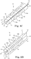
- FIGS. 3A-3D are perspective views of the lead implant tool 54 according to various embodiments of the present invention.
- the implant tool 54 is provided over a terminal connector of an implantable medical lead such as, for example terminal connector 60 of FIG. 2 .
- the implant tool 54 facilitates connection of variety of standard alligator clips to an implantable medical electrical lead in a safe, reliable manner that prevents the clips from shorting, and protects the terminal connector during testing and implantation of the lead.
- the implant tool 54 can be easily removed from the terminal connector so that the lead can be connected to the pulse generator.
- the implant tool 54 comes pre-mounted over the terminal connector of the lead such that when the physician removes the lead from its packaging from the manufacturer, the implant tool 54 is already in place and ready for use.
- the lead implant tool 54 is a light-weight, pliable polymer sheath 80.
- the pliable sheath 80 can be made from a variety of pliable polymers suitable for use in medical devices.
- the durometer of the polymer material used to form the pliable polymer sheath 80 is sufficiently low such that the pliable sheath 80 can conform to the terminal connector over which it is provided. Additionally, the durometer of the polymer material is sufficiently pliable such that the pliable polymer sheath 80 can be easily removed or peeled away from the terminal connector when the testing procedure and/or implantation of the lead is complete.
- the pliable sheath 80 is formed from 50A-70A durometer silicone.
- the pliable polymer sheath 80 defines a lumen 84 extending from a proximal end 88 through a distal end 92 of the pliable sheath 80.
- the lumen 84 is sized and shaped to receive a terminal connector of an implantable lead therein.
- an inner diameter d of the lumen 84 is slightly smaller than an outer diameter of the terminal connector such that compressive forces retain the implant tool 54 on the terminal connector.
- the polymer sheath 80 includes a proximal contact region 100 and a distal gripping region 104. At least two electrical contacts 108a, 108b are formed in the proximal contact region 100. In some embodiments, the proximal contact region 100 includes three electrical contacts, 108a, 108b and 108c. In other embodiments, the electrical contacts 108a-108c form pairs of diametrically opposed electrical contacts in the proximal contact region 100 of the pliable sheath 80.
- the electrical contacts 108a, 108b and 108c extend from an outer surface 112 to an inner surface 116 of the pliable sheath 80. In some embodiments, the electrical contacts 108a-108c extend partially around an outer circumference 117 of the pliable sheath 80. For example, in one embodiment, each of the electrical contacts 108a-108c may extend in an arc ranging from about 60 degrees to about 180 degrees about the outer circumference 117 of the pliable sheath. In another embodiment, each of the electrical contacts 108a-108c may extend in an arc ranging from about 180 degrees to about 360 degrees about the outer circumference 117 of the pliable sheath 80. In still yet another embodiment, each of the electrical contacts 108a-108c may extend 360 degrees about the outer circumference 117 of the pliable sheath.
- the electrical contacts 108a-108c can also include a depression 118 to facilitate contact with the corresponding electrical contacts (e.g., the terminal rings 66, 68, 70) on the terminal connector 60.
- the depression 118 can be a bump, wedge or notch formed in the electrical contacts 108a-108c that extends away from the inner surface 116 of the sheath 80 and into the lumen 84.
- the depression 118 may also serve as a guide for connection of the alligator clips to the terminal connector and may facilitate their retention.
- the electrical contacts 108a-108c are formed from a metal or metal alloy foil. Suitable metals for forming the electrical contacts 108a-108c include, but are not limited to gold, silver, platinum, palladium, titanium, nickel, iridium and their respective alloys.
- the electrical contacts 108a-108c are formed from a conductor-filled polymer.
- conductor-filled polymers include polyurethanes, silicone elastomers, or other polymeric materials that are compounded with a conductive material.
- Suitable conductive materials include, but are not limited to carbon, graphite, grapheme, nickel, silver, gold and combinations thereof.
- the conductive material can be provided in the form of microparticles or nanoparticles, microfibers or nanofibers, microspheres or nanospheres and/or nanotubes.
- the conductive material includes graphite nanotubes.
- the conductive material includes graphene.
- the conductive material includes a combination of silver and nickel spheres.
- the electrical contacts 108a-108c can be formed from a conductive polymer.
- Intrinsically conductive polymers are conductive without requiring a non-polymeric conductive filler or coating, such as metallic compound or carbon.
- Intrinsically conductive polymers include alternating single and double bonds forming a conjugated backbone that displays electronic properties. Charge in intrinsically conductive polymers is transported along and between polymer molecules via charge carriers generated along the conjugated backbone.
- Intrinsically conductive polymers may include dopants to enhance their conductivity. Dopants may also help to control the conductivity characteristics of the polymer.
- the conductivity of intrinsically conductive polymers can generally range from semiconducting to super conducting, depending upon the doping levels.
- intrinsically conductive polymers include, but are not limited to, the following: polypyrrole, polyacetylene, polythiophene, polyethylenedioxythiophene, poly (p-phenyl vinylene), polyaniline, polynapthalene, other suitable conductive polymers, and mixtures thereof.
- a conductive polymer or a conductor-filled polymer such as, for example, a conductor-filled silicone maintains the overall pliability of the implant tool 54.
- the conductive polymer material used to form the electrical contacts 108a-108c can be selected such that it is lower in durometer than the material used to form the remainder of the implant tool 54 such that the electrical contacts 108a-108c can be easily depressed to facilitate greater contact between the implant tool 54 and the electrodes on the terminal connector over which it is provided.
- the electrical contacts 108a-108c are formed from a conductor-filled silicone such as, for example, NuSil Technology R-2637, available from NuSil Technology of Carpinteria, CA.
- the inner surface 116 of the sheath 80 and the electrical contacts 108a-108c can be roughened. Roughening an inner surface of the electrical contacts 108a-108c may facilitate electrical contact between the electrical contacts 108-108c and their corresponding ring electrodes 66, 68 and 70 on the terminal connector 60.
- the inner surface of the electrical contacts has an average surface roughness (Ra) ranging from about 20 micro-inches to about 50 micro-inches. Additionally, the inner surface 116 of the sheath 80 may also be roughened.
- Roughening the inner surface of the sheath 80 reduces the contact area between the inner surface 116 of the sheath 80 and the outer surface of the implant tool 54 and may facilitate removal of the sheath 80 from about the terminal connector 60.
- the average surface roughness (Ra) of the inner surface 116 of the sheath 80 ranges from about 40 micro-inches to about 50 micro-inches.
- the proximal contact region 100 also includes at least one separation feature 120 disposed between adjacent electrical contacts or pairs of electrical contacts 108a-108c, such as electrical contacts 108a and 108b or electrical contacts 108b and 108c.
- the separation feature 120 is a polymer ridge that extends away from the outer surface 112 and at least partially around an outer circumference 117 of the pliable sheath.
- the separation feature 120 is a polymer ridge that extends away from the outer surface 112 and around the entire outer circumference 117 of the pliable sheath 80.
- the separation features 120 separate the electrical contacts 108a-108c from one another and prevent adjacent alligator clips from contacting one another when engaged with the implant tool 54. Additionally, the separation features 120 may serve as a visual guide for placement of the alligator clips in contact with the implant tool 54.
- the implant tool 54 also includes removal means for facilitating removal of the tool 54 from about the terminal connector when testing and implantation of the lead is complete.
- the distal gripping region 104 can include one or more tabs or wings 122 ( FIG. 3B ) to facilitate removal of the implant tool 54 from the terminal connector when testing and implantation of the lead is complete.
- the wings or tabs 122 can be used in combination with other removal means such as a slit 126 ( FIG. 3A ), perforation line 130 ( FIG. 3B ), tear strip 134 ( FIG. 3C ) or removable section 140 ( FIG. 3D ) to remove or "peel away" the implant tool 54.
- the removal means includes a slit 126 formed in the side wall 138 of the pliable sheath 80.
- the slit 126 extends in a direction along the longitudinal axis of the sheath from the proximal end 88 to the distal end 92 of the sheath 80.
- the slit 126 has a width w that is adapted to be increased from a first width to a second width to facilitate installation and removal of the implant tool 54 over the terminal connector of a lead.
- the slit 126 can have any number of cross-sectional shapes. In one embodiment, the slit 126 can have a tapered profile.
- the removal means includes one or more perforation lines 130 formed in the side wall 138 of the pliable sheath 80.
- the removal means includes one or more thin, frangible webs that facilitate removal of the sheath 80.
- the perforation lines 130 extend in a direction along the longitudinal axis of the sheath from the proximal end 88 to the distal end 92 of the sheath 80.
- the perforation lines 130 can be located 180 degrees from each other about the outer circumference 117 of the sheath 80 such that the sheath 80 can be split into two halves during the removal process.
- the individual perforations forming the perforation lines 130 can have any number of shapes useful for forming a perforation.
- the sheath 80 can also include one or more tabs 122 formed in the distal gripping region 104 of the sheath to facilitate removal of the sheath 80. The physician may pull on the tabs 122 to separate the sheath 80 at the perforation lines.
- the removal means can include a tear strip 134.
- the tear strip 134 is provided in a side wall 138 of the pliable sheath 80 and extends from the proximal end 88 to the distal end 92 of the sheath 80.
- the tear strip 134 can be formed from a tougher material than the remainder of the pliable sheath. The physician can pull on the tear strip 134 leaving behind a slit in the sheath which then facilitates removal of the implant tool 54 from about the terminal connector.
- the tear strip 134 can include a small lumen that is slightly smaller than the wall thickness of the sheath 80 having a removable strip. Removal of the tear strip 134 including the small lumen will result in a very thin walled structure that can be separated by pulling the sides of the sheath 80 away from each other.
- the removal means can include a removable section 140 that when removed leaves behind a slit in the side wall 138 of the sheath facilitating removal of the tool 54 from about the terminal connector.
- the removable section 140 can have a wedge-like shape and can be attached to a tab 122. Pulling on the tab 122 results in the removal of the removable section 140.
- the removable section 140 can be connected to the main portion of the sheath 80 by perforation lines or a thin, frangible web that facilitates easy separation of the removable section 140 from the sheath 80.
- FIGS. 4A-4C show various views of an implant tool 54 provided over the terminal connector 60 of an exemplary medical electrical lead 12.
- the implant tool 54 is provided over the terminal connector 60 such that the terminal pin 64 is exposed and accessible to a physician during the testing and implantation procedure.
- the implant tool 54 is positioned over the terminal connector 60 such that the middle electrical contact 108b is aligned with the middle electrode 68 on the terminal connector 60.
- the electrical contacts 108a-108c are spaced apart from one another such that alignment of the middle electrical contact 108b with the middle electrode 68 ensures proper positioning of the two remaining electrical contacts 108a and 108c relative to their corresponding electrodes 66 and 70 located on the terminal connector 60.
- the implant tool 54 includes a slit or other similar feature, the position of the implant tool 54 relative to the terminal connector 60 can be visually confirmed after installation.
- the implant tool 54 also includes an alignment feature to facilitate alignment of the electrical contacts 108a-c with the corresponding electrodes 66, 68 and 70 when the implant tool 54 is provided over the terminal connector 60 during the assembly process.
- the pliable sheath 80 forming the implant tool 54 may include one or more stop features or shoulders formed on an inner surface 116 of the pliable sheath 80.
- the pliable sheath 80 includes a proximal shoulder 146 adapted to abut the proximal end 150 of the terminal connector 60.
- the pliable sheath 80 can also include a distal shoulder 152 adapted to abut the implant tool 54.
- the width w1 of each of the electrical contacts 108a-108c is greater than the width w2 of each of the ring electrodes 66, 68 and 70 of the terminal connector 60.
- the alligator clips need not be secured to the implant tool 54 directly over the electrodes. Rather, the difference in width between the electrical contacts 108a-108c of the implant tool 54 and the ring electrodes 66, 68 and 70, facilitate an increase in the spacing between adjacent alligator clips secured to the implant tool 54 while at the same time maintaining good electrical contact with the respective electrodes 66, 68, and 70 located on the terminal connector 60.
- the electrical contacts 108a-108c can accommodate a wide variety of alligator clips of varying sizes from different manufacturers.
- FIG. 5 is a perspective view showing the lead implant tool 54 in use.
- the lead implant tool 54 is pre-mounted over the terminal connector 60 of a lead such that when the lead is removed from its packaging, the lead implant tool 54 is already in place over the terminal connector 60.
- the physician guides the lead 12 through the patient's vasculature to one of many potential implant sites.
- the function and location of the lead can be tested by connecting the conductors 62 of a Pacing System Analyzer (PSA) to the lead implant tool 54 disposed over the terminal connector 60.
- PSA Pacing System Analyzer
- the testing procedure is repeated each time the lead is repositioned until a suitable implant site is identified.
- the physician then completes the implantation procedure. After the implantation of the lead is complete, the physician removes the lead implant tool 54 from the terminal connector 60.
- PSA Pacing System Analyzer
- the implant tool 54 can be removed using one of the various removal means, described herein with reference to FIGS. 3A-3D according to the various embodiments of the present disclosure.
- the physician grips a tab such as, for example, tab 122 provided in the gripping region 104 of the lead implant tool 54 and uses the tab 122 to remove or peel-away the implant tool 54 from the terminal connector 60.
- the physician uses a first tab 122 to remove a section of the lead implant tool 54 leaving behind a slit. The physician then uses a second tab 122 provided on the gripping region 104 of the implant tool 54 to remove the tool 54 from the terminal connector 60.
- the physician grips a pair of tabs 122 located 180 degrees opposite one another in the gripping region 104 of the terminal tool 54. The physician then uses these tabs 122 to separate the implant tool 54 into two halves along a line of perforation or weakness.
- the terminal connector is then engaged with the header of the PG.
- a set of conductor-filled polymer rings is formed using a first shot mold having one or more cavities for forming the rings. Once molded and cured, the conductor-filled polymer rings can be placed over a core pin and into a second shot mold for overmolding of the non-conductive material portion of the implant tool 54.
- the second shot mold has the desired configuration of the implant tool 54.
- the conductor-filled polymer rings are placed over the core pin such that they have the desired spaced apart configuration. Non-conductive material is injected into the second shot mold, and the material cured. The finished implant tool 54 including the conductor filled polymer contacts is removed from the mold cavity and the core pin is removed.
- a conductor-filled polymer tube can be molded or extruded to the appropriate diameter and inner diameter. Additionally, the molded or extruded tube can be formed such that it includes features on the inner and/or conductor-filled polymer rings. The rings are then placed over a core pin such that they are spaced apart from one another at a desired distance. The core pin including the rings is then placed into a shot mold. The shot mold has the desired configuration of the implant tool 54. Non-conductive material is injected into the shot mold, and the material cured. The finished implant tool 54 including the conductor filled polymer contacts is removed from the mold cavity and the core pin is removed.
- Similar methods to those described herein can be used to form an implant tool 54 including metallic foil electrical contacts.
- Primer can be added to the non-conductive material to facilitate adhesion between the non-conductive material and the metallic contacts.
- a stamping process can be used to form metallic rings.
Landscapes
- Health & Medical Sciences (AREA)
- Engineering & Computer Science (AREA)
- Biomedical Technology (AREA)
- Nuclear Medicine, Radiotherapy & Molecular Imaging (AREA)
- Radiology & Medical Imaging (AREA)
- Life Sciences & Earth Sciences (AREA)
- Animal Behavior & Ethology (AREA)
- General Health & Medical Sciences (AREA)
- Public Health (AREA)
- Veterinary Medicine (AREA)
- Cardiology (AREA)
- Heart & Thoracic Surgery (AREA)
- Electrotherapy Devices (AREA)
Description
- The present invention generally relates to implantable medical devices. More particularly, the present invention relates to devices, systems and methods for installing and testing multi-conductor leads within a patient's body.
- Various types of medical electrical leads for use in cardiac rhythm management (CRM) and neurostimulation applications are known. In CRM applications, for example, such leads are frequently delivered intravascularly to an implantation location on or within a patient's heart, typically under the aid of fluoroscopy. Once implanted, the lead is coupled to a pulse generator or other implantable device for sensing cardiac electrical activity, delivering therapeutic stimuli, and/or for performing some other desired function within the body. Such leads often include a distal electrode end which contacts the heart tissue, and a proximal, terminal end which is connected to the pulse generator. The distal electrode end of the lead typically includes one or more features such as an active fixation helix or a number of passive tines to facilitate securing the lead to the heart tissue. The terminal end of the lead, in turn, includes one or more electrical contacts that are electrically connected to the electrodes on the terminal end of the lead via a number of conductors.
- In certain applications, the leads are tested for proper positioning and function as part of the implantation process and prior to being connected to the pulse generator, allowing the implanting physician to evaluate pacing and sensing performance prior to concluding that the particular lead position is suitable. During the testing process, for example, a Pacing System Analyzer (PSA) may be connected to the terminal end of the lead to evaluate the performance of the lead. To facilitate connection of the PSA to the lead, a lead implant tool can be temporarily coupled to the terminal end of the lead, allowing the conductors of the PSA to be connected to the electrical contacts on the terminal end of the lead. In some cases, for example, the implant tool may facilitate the attachment of several alligator clips, plunger cups, or other spring-loaded cups to the electrical contacts on the terminal end of the lead. Examples of lead implant tools for use in connecting the conductors of a PSA to a multi-conductor lead are described in
U.S. Patent Publication No, 2005/0177199 to Hansen et at andU.S. Patent Publication No. 2006/0258193 to Hoecke et al. - More recent trends in lead designs have focused on the development of lead connectors with up to four electrical contacts. The terminal end of such leads are not significantly different in size from previous, IS-1 standard leads, which include only two terminal contacts. Many existing spring-loaded clips used for connecting the PSA to the terminal contacts are often inadequate for use with more modern lead designs, particularly due to the limited spacing between the contacts, and since the space between the contacts is sometimes used as a sealing area to ensure electrical isolation.
-
US 2004/230268 A1 relates to a medical lead adapter assembly for facilitating an electrical connection between an implantable medical lead connector and an external medical device. The adapter includes a housing, having a sidewall and a longitudinally extending connector receptacle, and at least one contact opening passing through the sidewall to the receptacle. The contact opening is positioned in a location corresponding with at least one ring contact of the lead connector, when the lead connector is engaged within the receptacle, and allows electrical connection between at least one contact element of the external medical device and the at least one ring contact of the lead connector. -
US 2004/230268 A1 does not disclose an implant tool comprising a pliable sheath, wherein the pliable sheath comprises at least one tear strip extending from a proximal end to a distal end of the pliable sheath - The invention relates to an implant tool according to claim 1 and to a lead assembly according to claim 11.
-
-
Fig. 1 is a schematic view showing an illustrative system for implanting and testing an implantable lead within the body of a patient. -
Fig. 2 is a perspective view showing the terminal end of the implantable lead ofFig. 1 in greater detail. -
FIGS. 3A-3D are perspective views of a lead implant tool according to various embodiments of the present disclosure. -
FIG. 4A is a diagrammatic view of a lead assembly including an implant tool provided over a terminal connector of a lead in accordance with an embodiment -
FIG. 4B is a longitudinal cross-sectional view taken alongline 4B-4B of the implant tool and terminal connector shown inFIG. 4A . -
FIG. 4C is an end cross-sectional view taken alongline 4C-4C of the implant tool and terminal connector shown inFIG. 4A . -
FIG. 5 is a schematic view showing a lead implant tool in use in accordance with an embodiment. -
Fig. 1 is a schematic view showing anillustrative system 10 for implanting and testing an implantable lead 12 within the body of a patient. For purposes of illustration and not limitation, thesystem 10 is described in conjunction with an implantable lead 12 for use in sensing cardiac electrical activity and/or for providing electrical stimulus therapy to a patient'sheart 14. Thesystem 10 can be used in other contexts where implantable leads are employed, and where testing is to be conducted prior to the connection of the lead to another implantable device such as a pulse generator. In certain embodiments, for example, thesystem 10 can be used to aid in the implantation and testing of an implantable neurostimulation lead prior to its connection to another implantable device such as a pulse generator. - According to various embodiments, the lead 12 includes a lead body 16 extending from a
proximal end 18 adapted to be coupled to a pulse generator to adistal end 22. The lead 12 can be implanted in the patient'sheart 14, which as shown inFIG. 1 , includes aright atrium 24, aright ventricle 26, a left atrium 28, and aleft ventricle 30. In the embodiment illustrated inFIG. 1 , thedistal end 22 of the lead 12 is transvenously guided through theright atrium 24, through the coronary sinus ostium 32, and into a branch of the coronary sinus 36 or greatcardiac vein 38. The illustrated position of the lead 12 can be used for sensing or for delivering pacing energy to the left side ofheart 14, or to treat arrhythmias or other cardiac disorders requiring therapy delivered to the left side of theheart 14. Additionally, in some embodiments, the lead 12 can be configured to provide treatment in other regions of the heart 14 (e.g., theright atrium 24 or right ventricle 26). The lead 12 can include one ormore electrodes 42 for providing electrical therapy to and/or sensing therapy to the patient'sheart 14. In certain embodiments, the implantable lead 12 is a quadripolar lead including fourelectrodes 42 located in adistal region 44 of the lead 12. - In the illustrative embodiment depicted, the
system 10 further includes animplant tool 54, a stiffening member such as a stylet or guidewire 56, and a Pacing System Analyzer (PSA) 58 that can be used for implanting and testing the lead 12 within the body. During the course of the procedure, to evaluate the viability of a potential stimulation site, the function and location of the lead 12 can be tested by connecting aterminal connector 60 located at theproximal end 18 of the lead 12 to severalelectrical conductors 62 of thePSA 58. This evaluation can be performed after implantation of the lead 12 at the potential stimulation site. Such testing can be performed, for example, to verify that theelectrodes 42 are properly positioned on or within theheart 14. ThePSA 58 can also be used to perform other functions such as measuring pacing thresholds, lead impedance and r-wave amplitude. - The
implant tool 54 can be used with passive fixation leads to enable stylet or guidewire passage and electrical connection while protecting theterminal connector 60. In other embodiments, other fixation mechanisms such as, for example, a fixation helix, can also be deployed via theimplant tool 54. Theimplant tool 54 is configured to permit the implanting physician to easily feed various stylets or guidewires 56 into a pin lumen of the implantable lead 12, to make an electrical connection between thePSA conductors 62 and a terminal pin 64 (FIG. 2 ) and one or moreterminal ring electrodes FIG. 2 ) on the lead 12. - In some embodiments, the
implant tool 54 can be packaged and shipped already attached to an implantable lead 12. The pre-assembled components can then be packaged in a blister pack, pouch, or other suitable storage medium for later use by the implanting physician. - In use, the
implant tool 54 protects thelead terminal connector 60 throughout the implant procedure from electrical clips or other surgical implements. As such, theimplant tool 54 is configured such that it can remain coupled to the lead connector throughout the implantation and testing procedures, up to the point where the lead can be connected to another implantable device such as a pulse generator. At that time, thelead implant tool 54 is removed from the lead 12, and the lead 12 is then connected to the pulse generator. During normal operation, the lead 12 is configured to convey electrical signals back and forth between the pulse generator and theheart 14. For example, in those embodiments where the pulse generator is a pacemaker, the lead 12 can be used to deliver electrical therapeutic stimulus for pacing theheart 14. In those embodiments where the pulse generator is an implantable cardioverter defibrillator (ICD), the lead 12 can be utilized to deliver electric shocks to theheart 14 in response to an event such as a heart attack or ventricular tachycardia. In some embodiments, the pulse generator includes both pacing and defibrillation capabilities, or is capable of performing biventricular or other multi-site resynchronization therapies such as cardiac resynchronization therapy (CRT). Example leads and lead connectors that can be used in conjunction with theimplant tool 54 can include, but are not limited to, pacing and CRT leads (e.g., including a quadripolar connector or IS-4 type connector), ICD leads (e.g., including a quadripolar, IS-4/DF-4 type connector), and pacing leads with sensing capabilities (e.g., a pressure sensing/pacing lead with a quadripolar type connector). Other types of leads and/or lead connector types can also be used in conjunction with theimplant tool 54, as desired. -
Fig. 2 is a perspective view showing the IS-4terminal connector 60 of the implantable lead 12 ofFig. 1 in greater detail. As further shown inFig. 2 , the IS-4terminal connector 60 includes aterminal pin 64 and a number of terminal rings 66, 68, 70 each spaced axially apart from each other at a distance D1 along the length of theterminal connector 60. Theterminal pin 64 is coupled to a first, distalmost electrode 42 located in thedistal region 44 of the lead 12 and serves as the cathode for the implantable lead 12. The firstterminal ring 66 is electrically coupled to asecond electrode 42, which can serve as a cathode or an anode for the implantable lead 12. The second and thirdterminal ring electrodes distal region 44 of the implantable lead 12. - Additionally, although the implantable lead 12 includes a
terminal connector 60 having aterminal pin 64 and threeterminal rings -
FIGS. 3A-3D are perspective views of thelead implant tool 54 according to various embodiments of the present invention. According to various embodiments, theimplant tool 54 is provided over a terminal connector of an implantable medical lead such as, forexample terminal connector 60 ofFIG. 2 . Theimplant tool 54 facilitates connection of variety of standard alligator clips to an implantable medical electrical lead in a safe, reliable manner that prevents the clips from shorting, and protects the terminal connector during testing and implantation of the lead. After testing and implantation of the lead is complete, theimplant tool 54 can be easily removed from the terminal connector so that the lead can be connected to the pulse generator. In some embodiments, theimplant tool 54 comes pre-mounted over the terminal connector of the lead such that when the physician removes the lead from its packaging from the manufacturer, theimplant tool 54 is already in place and ready for use. - According to various embodiments of the present disclosure, as shown in
FIGS. 3A-3D , thelead implant tool 54 is a light-weight,pliable polymer sheath 80. Thepliable sheath 80 can be made from a variety of pliable polymers suitable for use in medical devices. The durometer of the polymer material used to form thepliable polymer sheath 80 is sufficiently low such that thepliable sheath 80 can conform to the terminal connector over which it is provided. Additionally, the durometer of the polymer material is sufficiently pliable such that thepliable polymer sheath 80 can be easily removed or peeled away from the terminal connector when the testing procedure and/or implantation of the lead is complete. In one non-limiting embodiment, thepliable sheath 80 is formed from 50A-70A durometer silicone. - The
pliable polymer sheath 80 defines alumen 84 extending from aproximal end 88 through adistal end 92 of thepliable sheath 80. Thelumen 84 is sized and shaped to receive a terminal connector of an implantable lead therein. In one embodiment, an inner diameter d of thelumen 84 is slightly smaller than an outer diameter of the terminal connector such that compressive forces retain theimplant tool 54 on the terminal connector. - Additionally, the
polymer sheath 80 includes aproximal contact region 100 and a distalgripping region 104. At least twoelectrical contacts proximal contact region 100. In some embodiments, theproximal contact region 100 includes three electrical contacts, 108a, 108b and 108c. In other embodiments, theelectrical contacts 108a-108c form pairs of diametrically opposed electrical contacts in theproximal contact region 100 of thepliable sheath 80. - The
electrical contacts outer surface 112 to aninner surface 116 of thepliable sheath 80. In some embodiments, theelectrical contacts 108a-108c extend partially around anouter circumference 117 of thepliable sheath 80. For example, in one embodiment, each of theelectrical contacts 108a-108c may extend in an arc ranging from about 60 degrees to about 180 degrees about theouter circumference 117 of the pliable sheath. In another embodiment, each of theelectrical contacts 108a-108c may extend in an arc ranging from about 180 degrees to about 360 degrees about theouter circumference 117 of thepliable sheath 80. In still yet another embodiment, each of theelectrical contacts 108a-108c may extend 360 degrees about theouter circumference 117 of the pliable sheath. - As shown in
FIGS. 3A, 3B and3D , theelectrical contacts 108a-108c can also include adepression 118 to facilitate contact with the corresponding electrical contacts (e.g., the terminal rings 66, 68, 70) on theterminal connector 60. Thedepression 118 can be a bump, wedge or notch formed in theelectrical contacts 108a-108c that extends away from theinner surface 116 of thesheath 80 and into thelumen 84. On theouter surface 112 of the sheath, thedepression 118 may also serve as a guide for connection of the alligator clips to the terminal connector and may facilitate their retention. - In some embodiments, the
electrical contacts 108a-108c are formed from a metal or metal alloy foil. Suitable metals for forming theelectrical contacts 108a-108c include, but are not limited to gold, silver, platinum, palladium, titanium, nickel, iridium and their respective alloys. - In other embodiments, the
electrical contacts 108a-108c are formed from a conductor-filled polymer. Examples of conductor-filled polymers include polyurethanes, silicone elastomers, or other polymeric materials that are compounded with a conductive material. Suitable conductive materials include, but are not limited to carbon, graphite, grapheme, nickel, silver, gold and combinations thereof. The conductive material can be provided in the form of microparticles or nanoparticles, microfibers or nanofibers, microspheres or nanospheres and/or nanotubes. In one embodiment, the conductive material includes graphite nanotubes. In another embodiment, the conductive material includes graphene. In still another embodiment, the conductive material includes a combination of silver and nickel spheres. - In still other embodiments, the
electrical contacts 108a-108c can be formed from a conductive polymer. Intrinsically conductive polymers are conductive without requiring a non-polymeric conductive filler or coating, such as metallic compound or carbon. Intrinsically conductive polymers include alternating single and double bonds forming a conjugated backbone that displays electronic properties. Charge in intrinsically conductive polymers is transported along and between polymer molecules via charge carriers generated along the conjugated backbone. Intrinsically conductive polymers may include dopants to enhance their conductivity. Dopants may also help to control the conductivity characteristics of the polymer. The conductivity of intrinsically conductive polymers can generally range from semiconducting to super conducting, depending upon the doping levels. Examples of intrinsically conductive polymers include, but are not limited to, the following: polypyrrole, polyacetylene, polythiophene, polyethylenedioxythiophene, poly (p-phenyl vinylene), polyaniline, polynapthalene, other suitable conductive polymers, and mixtures thereof. - Using a conductive polymer or a conductor-filled polymer such as, for example, a conductor-filled silicone maintains the overall pliability of the
implant tool 54. Additionally, the conductive polymer material used to form theelectrical contacts 108a-108c can be selected such that it is lower in durometer than the material used to form the remainder of theimplant tool 54 such that theelectrical contacts 108a-108c can be easily depressed to facilitate greater contact between theimplant tool 54 and the electrodes on the terminal connector over which it is provided. In one embodiment, theelectrical contacts 108a-108c are formed from a conductor-filled silicone such as, for example, NuSil Technology R-2637, available from NuSil Technology of Carpinteria, CA. - In some embodiments, the
inner surface 116 of thesheath 80 and theelectrical contacts 108a-108c can be roughened. Roughening an inner surface of theelectrical contacts 108a-108c may facilitate electrical contact between the electrical contacts 108-108c and theircorresponding ring electrodes terminal connector 60. In one embodiment, the inner surface of the electrical contacts has an average surface roughness (Ra) ranging from about 20 micro-inches to about 50 micro-inches. Additionally, theinner surface 116 of thesheath 80 may also be roughened. Roughening the inner surface of thesheath 80 reduces the contact area between theinner surface 116 of thesheath 80 and the outer surface of theimplant tool 54 and may facilitate removal of thesheath 80 from about theterminal connector 60. In some embodiments the average surface roughness (Ra) of theinner surface 116 of thesheath 80 ranges from about 40 micro-inches to about 50 micro-inches. - According to various embodiments, as shown in
FIGS. 3A-3D , theproximal contact region 100 also includes at least oneseparation feature 120 disposed between adjacent electrical contacts or pairs ofelectrical contacts 108a-108c, such aselectrical contacts electrical contacts separation feature 120 is a polymer ridge that extends away from theouter surface 112 and at least partially around anouter circumference 117 of the pliable sheath. In other embodiments, theseparation feature 120 is a polymer ridge that extends away from theouter surface 112 and around the entireouter circumference 117 of thepliable sheath 80. The separation features 120 separate theelectrical contacts 108a-108c from one another and prevent adjacent alligator clips from contacting one another when engaged with theimplant tool 54. Additionally, the separation features 120 may serve as a visual guide for placement of the alligator clips in contact with theimplant tool 54. - The
implant tool 54 also includes removal means for facilitating removal of thetool 54 from about the terminal connector when testing and implantation of the lead is complete. According to some embodiments, the distalgripping region 104 can include one or more tabs or wings 122 (FIG. 3B ) to facilitate removal of theimplant tool 54 from the terminal connector when testing and implantation of the lead is complete. The wings ortabs 122 can be used in combination with other removal means such as a slit 126 (FIG. 3A ), perforation line 130 (FIG. 3B ), tear strip 134 (FIG. 3C ) or removable section 140 (FIG. 3D ) to remove or "peel away" theimplant tool 54. - In some embodiments, as shown in
FIG. 3A , the removal means includes aslit 126 formed in theside wall 138 of thepliable sheath 80. Theslit 126 extends in a direction along the longitudinal axis of the sheath from theproximal end 88 to thedistal end 92 of thesheath 80. Theslit 126 has a width w that is adapted to be increased from a first width to a second width to facilitate installation and removal of theimplant tool 54 over the terminal connector of a lead. Theslit 126 can have any number of cross-sectional shapes. In one embodiment, theslit 126 can have a tapered profile. - In other embodiments, as shown in
FIG. 3B , the removal means includes one ormore perforation lines 130 formed in theside wall 138 of thepliable sheath 80. In other embodiments, the removal means includes one or more thin, frangible webs that facilitate removal of thesheath 80. The perforation lines 130 extend in a direction along the longitudinal axis of the sheath from theproximal end 88 to thedistal end 92 of thesheath 80. The perforation lines 130 can be located 180 degrees from each other about theouter circumference 117 of thesheath 80 such that thesheath 80 can be split into two halves during the removal process. The individual perforations forming theperforation lines 130 can have any number of shapes useful for forming a perforation. In a further embodiment, as shown, thesheath 80 can also include one ormore tabs 122 formed in the distalgripping region 104 of the sheath to facilitate removal of thesheath 80. The physician may pull on thetabs 122 to separate thesheath 80 at the perforation lines. - In still other embodiments, as shown in
FIG. 3C , the removal means can include atear strip 134. Thetear strip 134 is provided in aside wall 138 of thepliable sheath 80 and extends from theproximal end 88 to thedistal end 92 of thesheath 80. Thetear strip 134 can be formed from a tougher material than the remainder of the pliable sheath. The physician can pull on thetear strip 134 leaving behind a slit in the sheath which then facilitates removal of theimplant tool 54 from about the terminal connector. Alternatively, thetear strip 134 can include a small lumen that is slightly smaller than the wall thickness of thesheath 80 having a removable strip. Removal of thetear strip 134 including the small lumen will result in a very thin walled structure that can be separated by pulling the sides of thesheath 80 away from each other. - In still yet other embodiments, as shown in
FIG. 3D , the removal means can include aremovable section 140 that when removed leaves behind a slit in theside wall 138 of the sheath facilitating removal of thetool 54 from about the terminal connector. As shown inFIG. 3D , theremovable section 140 can have a wedge-like shape and can be attached to atab 122. Pulling on thetab 122 results in the removal of theremovable section 140. Theremovable section 140 can be connected to the main portion of thesheath 80 by perforation lines or a thin, frangible web that facilitates easy separation of theremovable section 140 from thesheath 80. -
FIGS. 4A-4C show various views of animplant tool 54 provided over theterminal connector 60 of an exemplary medical electrical lead 12. As shown inFIGS. 4A-4C , theimplant tool 54 is provided over theterminal connector 60 such that theterminal pin 64 is exposed and accessible to a physician during the testing and implantation procedure. According to various embodiments, theimplant tool 54 is positioned over theterminal connector 60 such that the middleelectrical contact 108b is aligned with themiddle electrode 68 on theterminal connector 60. Theelectrical contacts 108a-108c are spaced apart from one another such that alignment of the middleelectrical contact 108b with themiddle electrode 68 ensures proper positioning of the two remainingelectrical contacts corresponding electrodes terminal connector 60. If theimplant tool 54 includes a slit or other similar feature, the position of theimplant tool 54 relative to theterminal connector 60 can be visually confirmed after installation. - According to various embodiments, the
implant tool 54 also includes an alignment feature to facilitate alignment of theelectrical contacts 108a-c with the correspondingelectrodes implant tool 54 is provided over theterminal connector 60 during the assembly process. For example in some embodiments, as shown inFIGS. 4A-4C , thepliable sheath 80 forming theimplant tool 54 may include one or more stop features or shoulders formed on aninner surface 116 of thepliable sheath 80. In one embodiment, thepliable sheath 80 includes aproximal shoulder 146 adapted to abut theproximal end 150 of theterminal connector 60. In addition, thepliable sheath 80 can also include adistal shoulder 152 adapted to abut theimplant tool 54. - In some embodiments, as shown in
FIGS. 4A and 4B , the width w1 of each of theelectrical contacts 108a-108c is greater than the width w2 of each of thering electrodes terminal connector 60. Thus, the alligator clips need not be secured to theimplant tool 54 directly over the electrodes. Rather, the difference in width between theelectrical contacts 108a-108c of theimplant tool 54 and thering electrodes implant tool 54 while at the same time maintaining good electrical contact with therespective electrodes terminal connector 60. Additionally, when the width w1 of each of theelectrical contacts 108a-108c is greater that the width w2 of each of thering electrodes terminal connector 60, theelectrical contacts 108a-108c can accommodate a wide variety of alligator clips of varying sizes from different manufacturers. -
FIG. 5 is a perspective view showing thelead implant tool 54 in use. In various embodiments, thelead implant tool 54 is pre-mounted over theterminal connector 60 of a lead such that when the lead is removed from its packaging, thelead implant tool 54 is already in place over theterminal connector 60. The physician guides the lead 12 through the patient's vasculature to one of many potential implant sites. To evaluate the viability of the potential implant site, the function and location of the lead can be tested by connecting theconductors 62 of a Pacing System Analyzer (PSA) to thelead implant tool 54 disposed over theterminal connector 60. The testing procedure is repeated each time the lead is repositioned until a suitable implant site is identified. The physician then completes the implantation procedure. After the implantation of the lead is complete, the physician removes thelead implant tool 54 from theterminal connector 60. - The
implant tool 54 can be removed using one of the various removal means, described herein with reference toFIGS. 3A-3D according to the various embodiments of the present disclosure. In one embodiment, the physician grips a tab such as, for example,tab 122 provided in thegripping region 104 of thelead implant tool 54 and uses thetab 122 to remove or peel-away theimplant tool 54 from theterminal connector 60. In another embodiment, the physician uses afirst tab 122 to remove a section of thelead implant tool 54 leaving behind a slit. The physician then uses asecond tab 122 provided on thegripping region 104 of theimplant tool 54 to remove thetool 54 from theterminal connector 60. In yet another embodiment, the physician grips a pair oftabs 122 located 180 degrees opposite one another in thegripping region 104 of theterminal tool 54. The physician then uses thesetabs 122 to separate theimplant tool 54 into two halves along a line of perforation or weakness. - After the
implant tool 54 has been removed from theterminal connector 60, the terminal connector is then engaged with the header of the PG. - Methods for forming the
implant tool 54, described herein according to the various embodiments, will now be described. - In one embodiment, to form the
implant tool 54 including the conductor-filled polymer contacts, a set of conductor-filled polymer rings is formed using a first shot mold having one or more cavities for forming the rings. Once molded and cured, the conductor-filled polymer rings can be placed over a core pin and into a second shot mold for overmolding of the non-conductive material portion of theimplant tool 54. The second shot mold has the desired configuration of theimplant tool 54. The conductor-filled polymer rings are placed over the core pin such that they have the desired spaced apart configuration. Non-conductive material is injected into the second shot mold, and the material cured. Thefinished implant tool 54 including the conductor filled polymer contacts is removed from the mold cavity and the core pin is removed. - In another embodiment, a conductor-filled polymer tube can be molded or extruded to the appropriate diameter and inner diameter. Additionally, the molded or extruded tube can be formed such that it includes features on the inner and/or conductor-filled polymer rings. The rings are then placed over a core pin such that they are spaced apart from one another at a desired distance. The core pin including the rings is then placed into a shot mold. The shot mold has the desired configuration of the
implant tool 54. Non-conductive material is injected into the shot mold, and the material cured. Thefinished implant tool 54 including the conductor filled polymer contacts is removed from the mold cavity and the core pin is removed. - Similar methods to those described herein can be used to form an
implant tool 54 including metallic foil electrical contacts. Primer can be added to the non-conductive material to facilitate adhesion between the non-conductive material and the metallic contacts. Also, in some embodiments, a stamping process can be used to form metallic rings.
Claims (12)
- An implant tool (54) for use with an implantable lead (12) during an implant procedure, the implant tool (54) comprising:a pliable sheath (80) having an inner surface (116) and an outer surface (112) and comprising a proximal contact region (100) and a distal gripping region (104), the pliable sheath (80) defining a lumen (84) extending from a proximal end (88) through a distal end (92) of the pliable sheath (80), the lumen (84) sized to receive a terminal connector (60) of an implantable lead (12) therein, wherein the pliable sheath (80) further comprises at least one tear strip (134) extending from the proximal end (88) to the distal end (92) of the pliable sheath (80);at least a first and a second electrical contact (108a, 108b) formed in the proximal contact region (100) of the pliable sheath (80), the first and second electrical contacts (108a, 108b) extending from the outer surface (112) to the inner surface (116) of the pliable sheath (80) and comprising an electrically conductive material;at least a first raised separation feature (120) formed on the outer surface (112) of the pliable sheath (80), the first raised separation feature (120) disposed between the first and second electrical contacts (108a, 108b).
- The implant tool (54) according to claim 1, wherein the raised separation feature (120) extends about 360 degrees about an outer circumference of the pliable sheath (80).
- The implant tool (54) according to claim 1, wherein the electrically conductive material comprises an electrically conductive polymer.
- The implant tool (54) according to claim 1, wherein the electrically conductive material comprises a polymer comprising electrically conductive particles dispersed therein.
- The implant tool (54) according to claim 1, wherein the electrically conductive material comprises a silicone rubber having a combination of silver and nickel particles dispersed therein.
- The implant tool (54) according to claim 1, wherein the electrically conductive material comprises a conductive metal foil.
- The implant tool (54) according to claim 1, wherein the gripping portion comprises at least one tab (122) extending away from the pliable sheath (80) and adapted to be gripped by a user to remove the pliable sheath (80) from about a terminal connector (60) of the lead when in use.
- The implant tool (54) according to claim 1, wherein the pliable sheath (80) further comprises a side slit (126) formed in the wall of the pliable sheath (80), the slit (126) extending from the proximal end (88) to the distal end (92) of the pliable sheath (80) and having a width w that is adapted to be increased from a first width to a second width to facilitate attachment and/or removal of the pliable sheath (80).
- The implant tool (54) according to claim 1, wherein the pliable sheath (80) further comprises at least one line of perforations or thin, frangible web extending from the proximal end (88) to the distal end (92) of the sheath (80).
- The implant tool (54) according to claim 1, wherein the pliable sheath (80) further comprises a removable portion extending from the proximal end (88) to the distal end (92) of the pliable sheath (80).
- A lead assembly comprising:an implantable medical electrical lead including a terminal connector (60) adapted to be coupled to a pulse generator, the terminal connector (60) comprising a terminal pin (64), a proximal ring electrode (70), a middle ring electrode (68) and a distal ring electrode (66); anda lead implant tool (54) according to claim 1, wherein said lead implant tool is disposed over the terminal connector (60).
- The lead assembly according to claim 11, wherein the lead implant tool (54) is disposed over the terminal connector (60) such that the second electrical contact is aligned over the middle ring electrode (68) of the terminal connector (60) and/or
wherein the first and second electrical contacts (108a, 108b) of the lead implant tool (54) comprise a depression extending away from an inner surface (116) of the implant tool (54) in a direction toward the terminal connector (60) over which the lead implant tool (54) is disposed and/or
wherein the implant tool (54) further comprises a roughened inner surface (116) and/or
wherein the electrically conductive material forming the first and second electrical contacts (108a, 108b) of the implant tool (54) comprises an electrically conductive polymer and/or
wherein a width of the first and second electrical contacts (108a, 108b) is greater than a width of the corresponding ring electrode over which the first and second electrical contacts (108a, 108b) are disposed and/or
wherein the lead implant tool (54) is disposed over the terminal connector (60) such that the terminal pin is exposed and accessible to a user and/or
wherein the lead implant tool (54) further comprises removal means for removing the lead implant tool (54) from the terminal connector (60) prior to connection of the terminal connector (60) to a pulse generator.
Applications Claiming Priority (2)
| Application Number | Priority Date | Filing Date | Title |
|---|---|---|---|
| US41555510P | 2010-11-19 | 2010-11-19 | |
| PCT/US2011/054887 WO2012067728A1 (en) | 2010-11-19 | 2011-10-05 | Peel-away is-4/df-4 lead implant tool with electrical contacts |
Publications (2)
| Publication Number | Publication Date |
|---|---|
| EP2640463A1 EP2640463A1 (en) | 2013-09-25 |
| EP2640463B1 true EP2640463B1 (en) | 2017-05-10 |
Family
ID=44800288
Family Applications (1)
| Application Number | Title | Priority Date | Filing Date |
|---|---|---|---|
| EP11770027.8A Active EP2640463B1 (en) | 2010-11-19 | 2011-10-05 | Peel-away is-4/df-4 lead implant tool with electrical contacts |
Country Status (5)
| Country | Link |
|---|---|
| US (2) | US8666514B2 (en) |
| EP (1) | EP2640463B1 (en) |
| JP (1) | JP5669948B2 (en) |
| AU (1) | AU2011329457B2 (en) |
| WO (1) | WO2012067728A1 (en) |
Families Citing this family (22)
| Publication number | Priority date | Publication date | Assignee | Title |
|---|---|---|---|---|
| US8870950B2 (en) | 2009-12-08 | 2014-10-28 | Mitral Tech Ltd. | Rotation-based anchoring of an implant |
| WO2012067728A1 (en) * | 2010-11-19 | 2012-05-24 | Cardiac Pacemakers, Inc. | Peel-away is-4/df-4 lead implant tool with electrical contacts |
| US9332851B2 (en) | 2013-03-15 | 2016-05-10 | Hni Technologies Inc. | Chair with activated back flex |
| US9106004B2 (en) | 2013-12-19 | 2015-08-11 | Medtronic, Inc. | Implantable medical electrical leads and connector assemblies thereof |
| US10456587B2 (en) | 2015-06-18 | 2019-10-29 | Cardiac Pacemakers, Inc. | Terminal connector insertion tool aid |
| DE102015114742B4 (en) * | 2015-09-03 | 2017-06-14 | Imk Automotive Gmbh | Kinematics for an intracorporeally driven instrument of an endoscope |
| DE102016209871A1 (en) | 2016-06-06 | 2017-12-07 | Robert Bosch Gmbh | Punching device and method for punching a lumen and implanting an implant device |
| DE102018201030B4 (en) | 2018-01-24 | 2025-10-16 | Kardion Gmbh | Magnetic dome element with magnetic bearing function |
| DE102018204604A1 (en) | 2018-03-27 | 2019-10-02 | Kardion Gmbh | Plug and plug system for contacting a cable with an implantable device and method for contacting |
| DE102018204610A1 (en) | 2018-03-27 | 2019-10-02 | Kardion Gmbh | Plug for contacting a cable with an implantable device and cable with plug and manufacturing method |
| DE102018206727A1 (en) | 2018-05-02 | 2019-11-07 | Kardion Gmbh | Energy transmission system and receiving unit for wireless transcutaneous energy transmission |
| DE102018206724A1 (en) | 2018-05-02 | 2019-11-07 | Kardion Gmbh | Energy transmission system and method for wireless energy transmission |
| DE102018206725A1 (en) | 2018-05-02 | 2019-11-07 | Kardion Gmbh | Receiving unit, transmitting unit, energy transmission system and method for wireless energy transmission |
| DE102018206750A1 (en) | 2018-05-02 | 2019-11-07 | Kardion Gmbh | Device for inductive energy transfer into a human body and its use |
| DE102018206754A1 (en) | 2018-05-02 | 2019-11-07 | Kardion Gmbh | Method and device for determining the temperature at a surface and use of the method |
| DE102018206731A1 (en) | 2018-05-02 | 2019-11-07 | Kardion Gmbh | Device for inductive energy transmission in a human body and use of the device |
| DE102018208555A1 (en) | 2018-05-30 | 2019-12-05 | Kardion Gmbh | Apparatus for anchoring a cardiac assist system in a blood vessel, method of operation, and method of making a device and cardiac assist system |
| DE102018208927A1 (en) | 2018-06-06 | 2019-12-12 | Kardion Gmbh | An implantable device for determining a fluid volume flow through a blood vessel |
| US10828487B2 (en) * | 2018-10-16 | 2020-11-10 | Advanced Bionics Ag | Cochlear implant assemblies and methods for manufacturing the same |
| JP7535230B2 (en) * | 2019-04-29 | 2024-08-16 | コーニンクレッカ フィリップス エヌ ヴェ | Lead Engagement Device |
| CN114055705B (en) * | 2020-07-31 | 2023-08-04 | 西安敦博医疗器械有限公司 | Method for manufacturing implantable medical electrode catheter |
| US11699551B2 (en) | 2020-11-05 | 2023-07-11 | Kardion Gmbh | Device for inductive energy transmission in a human body and use of the device |
Family Cites Families (25)
| Publication number | Priority date | Publication date | Assignee | Title |
|---|---|---|---|---|
| US4166469A (en) * | 1977-12-13 | 1979-09-04 | Littleford Philip O | Apparatus and method for inserting an electrode |
| US4744370A (en) * | 1987-04-27 | 1988-05-17 | Cordis Leads, Inc. | Lead assembly with selectable electrode connection |
| US5931861A (en) * | 1997-04-25 | 1999-08-03 | Medtronic, Inc. | Medical lead adaptor having rotatable locking clip mechanism |
| US7013182B1 (en) * | 2000-05-04 | 2006-03-14 | Cardiac Pacemakers, Inc. | Conductive polymer sheath on defibrillator shocking coils |
| US6854994B2 (en) | 2001-04-19 | 2005-02-15 | Medtronic, Inc. | Medical electrical lead connector arrangement including anti-rotation means |
| US7674245B2 (en) | 2001-06-07 | 2010-03-09 | Cardiac Pacemakers, Inc. | Method and apparatus for an adjustable shape guide catheter |
| US7717899B2 (en) | 2002-01-28 | 2010-05-18 | Cardiac Pacemakers, Inc. | Inner and outer telescoping catheter delivery system |
| US7174211B2 (en) | 2002-10-18 | 2007-02-06 | Cardiac Pacemakers, Inc. | Header for implantable medical for use with both unipolar and bipolar leads |
| US7539542B1 (en) | 2003-01-09 | 2009-05-26 | Boston Scientific Neuromodulation Corporation | Lead connector, lead adapter, and lead insertion apparatus |
| US20040230269A1 (en) | 2003-05-13 | 2004-11-18 | Medtronic, Inc. | Medical lead adaptor assembly |
| US7130699B2 (en) | 2003-05-13 | 2006-10-31 | Medtronic, Inc. | Medical lead adaptor assembly |
| US8639340B2 (en) | 2003-08-06 | 2014-01-28 | Medtronic, Inc. | Implantable medical lead connector sleeves |
| US20050177199A1 (en) | 2004-02-09 | 2005-08-11 | Cardiac Pacemakers, Inc. | PSA cable and connector for quadripolar lead terminal |
| US20080015668A1 (en) * | 2004-02-23 | 2008-01-17 | Soukup Thomas M | Test Connector for Implantable Leads |
| US7877150B2 (en) * | 2004-03-30 | 2011-01-25 | Medtronic, Inc. | Lead electrode for use in an MRI-safe implantable medical device |
| US7753696B2 (en) | 2005-05-12 | 2010-07-13 | Cardiac Pacemakers, Inc. | Lead terminal multi-tool |
| EP2004287B1 (en) | 2006-03-23 | 2010-07-21 | Medtronic, Inc. | Medical electrical lead connection systems and methods |
| US7831312B2 (en) | 2006-09-29 | 2010-11-09 | Medtronic, Inc. | Floating adapter for use with auxiliary lead assembly |
| US7711428B2 (en) | 2007-01-18 | 2010-05-04 | Medtronic, Inc. | Hermetic lead connector assembly |
| US7758384B2 (en) | 2007-02-26 | 2010-07-20 | Medtronic, Inc. | Implantable bifurcated neurostimulator adapters |
| US7594828B2 (en) | 2007-02-26 | 2009-09-29 | Medtronic, Inc. | Implantable neurostimulator adapters |
| US9302092B2 (en) | 2009-12-30 | 2016-04-05 | Cardiac Pacemakers, Inc. | Multi-function lead implant tool |
| EP2533686B1 (en) * | 2010-02-12 | 2017-04-05 | Georgetown University | Polymer film bioelectrodes and methods of making and using the same |
| US9083129B2 (en) | 2010-07-14 | 2015-07-14 | Cardiac Pacemakers, Inc. | Multipolar lead evaluation device |
| WO2012067728A1 (en) * | 2010-11-19 | 2012-05-24 | Cardiac Pacemakers, Inc. | Peel-away is-4/df-4 lead implant tool with electrical contacts |
-
2011
- 2011-10-05 WO PCT/US2011/054887 patent/WO2012067728A1/en not_active Ceased
- 2011-10-05 US US13/253,336 patent/US8666514B2/en not_active Expired - Fee Related
- 2011-10-05 EP EP11770027.8A patent/EP2640463B1/en active Active
- 2011-10-05 AU AU2011329457A patent/AU2011329457B2/en not_active Ceased
- 2011-10-05 JP JP2013531967A patent/JP5669948B2/en not_active Expired - Fee Related
-
2014
- 2014-01-16 US US14/157,286 patent/US8792997B2/en active Active
Also Published As
| Publication number | Publication date |
|---|---|
| JP2013543402A (en) | 2013-12-05 |
| US8666514B2 (en) | 2014-03-04 |
| US20120130396A1 (en) | 2012-05-24 |
| WO2012067728A1 (en) | 2012-05-24 |
| US20140135884A1 (en) | 2014-05-15 |
| US8792997B2 (en) | 2014-07-29 |
| AU2011329457B2 (en) | 2015-01-22 |
| AU2011329457A1 (en) | 2013-03-14 |
| EP2640463A1 (en) | 2013-09-25 |
| JP5669948B2 (en) | 2015-02-18 |
Similar Documents
| Publication | Publication Date | Title |
|---|---|---|
| AU2011329457B2 (en) | Peel-away IS-4/DF-4 lead implant tool with electrical contacts | |
| EP2519316B1 (en) | Terminal connector assembly for a medical electrical lead | |
| US10084278B2 (en) | Implantable lead assembly | |
| US20030045912A1 (en) | Medical lead connector | |
| US7551967B1 (en) | Implantable medical leads and devices having carbon nanotube-based anti-electrostatic coatings and methods for making such leads and devices | |
| EP4041372B1 (en) | Medical device with braided tubular body | |
| JP2008538997A (en) | Medical electrode with conductive polymer | |
| WO2006012159A1 (en) | Multipolar medical electrical lead | |
| US9083129B2 (en) | Multipolar lead evaluation device | |
| US20040267328A1 (en) | Electrode selection system for medical electrical leads | |
| WO2013159031A2 (en) | Implantable medical device lead including a unifilar coiled cable | |
| WO2009094315A2 (en) | Medical electrical lead | |
| EP1666086B1 (en) | Automatic capture pacing lead | |
| US6374142B1 (en) | Isodiametric pacing/defibrillation lead | |
| WO2025133669A1 (en) | Multi-level electrode |
Legal Events
| Date | Code | Title | Description |
|---|---|---|---|
| PUAI | Public reference made under article 153(3) epc to a published international application that has entered the european phase |
Free format text: ORIGINAL CODE: 0009012 |
|
| 17P | Request for examination filed |
Effective date: 20130507 |
|
| AK | Designated contracting states |
Kind code of ref document: A1 Designated state(s): AL AT BE BG CH CY CZ DE DK EE ES FI FR GB GR HR HU IE IS IT LI LT LU LV MC MK MT NL NO PL PT RO RS SE SI SK SM TR |
|
| DAX | Request for extension of the european patent (deleted) | ||
| 17Q | First examination report despatched |
Effective date: 20160204 |
|
| GRAP | Despatch of communication of intention to grant a patent |
Free format text: ORIGINAL CODE: EPIDOSNIGR1 |
|
| INTG | Intention to grant announced |
Effective date: 20161130 |
|
| GRAS | Grant fee paid |
Free format text: ORIGINAL CODE: EPIDOSNIGR3 |
|
| GRAA | (expected) grant |
Free format text: ORIGINAL CODE: 0009210 |
|
| AK | Designated contracting states |
Kind code of ref document: B1 Designated state(s): AL AT BE BG CH CY CZ DE DK EE ES FI FR GB GR HR HU IE IS IT LI LT LU LV MC MK MT NL NO PL PT RO RS SE SI SK SM TR |
|
| REG | Reference to a national code |
Ref country code: GB Ref legal event code: FG4D |
|
| REG | Reference to a national code |
Ref country code: AT Ref legal event code: REF Ref document number: 891668 Country of ref document: AT Kind code of ref document: T Effective date: 20170515 Ref country code: CH Ref legal event code: EP |
|
| REG | Reference to a national code |
Ref country code: IE Ref legal event code: FG4D |
|
| REG | Reference to a national code |
Ref country code: DE Ref legal event code: R096 Ref document number: 602011037856 Country of ref document: DE |
|
| REG | Reference to a national code |
Ref country code: NL Ref legal event code: FP |
|
| REG | Reference to a national code |
Ref country code: LT Ref legal event code: MG4D |
|
| REG | Reference to a national code |
Ref country code: AT Ref legal event code: MK05 Ref document number: 891668 Country of ref document: AT Kind code of ref document: T Effective date: 20170510 |
|
| PG25 | Lapsed in a contracting state [announced via postgrant information from national office to epo] |
Ref country code: LT Free format text: LAPSE BECAUSE OF FAILURE TO SUBMIT A TRANSLATION OF THE DESCRIPTION OR TO PAY THE FEE WITHIN THE PRESCRIBED TIME-LIMIT Effective date: 20170510 Ref country code: ES Free format text: LAPSE BECAUSE OF FAILURE TO SUBMIT A TRANSLATION OF THE DESCRIPTION OR TO PAY THE FEE WITHIN THE PRESCRIBED TIME-LIMIT Effective date: 20170510 Ref country code: NO Free format text: LAPSE BECAUSE OF FAILURE TO SUBMIT A TRANSLATION OF THE DESCRIPTION OR TO PAY THE FEE WITHIN THE PRESCRIBED TIME-LIMIT Effective date: 20170810 Ref country code: GR Free format text: LAPSE BECAUSE OF FAILURE TO SUBMIT A TRANSLATION OF THE DESCRIPTION OR TO PAY THE FEE WITHIN THE PRESCRIBED TIME-LIMIT Effective date: 20170811 Ref country code: HR Free format text: LAPSE BECAUSE OF FAILURE TO SUBMIT A TRANSLATION OF THE DESCRIPTION OR TO PAY THE FEE WITHIN THE PRESCRIBED TIME-LIMIT Effective date: 20170510 Ref country code: AT Free format text: LAPSE BECAUSE OF FAILURE TO SUBMIT A TRANSLATION OF THE DESCRIPTION OR TO PAY THE FEE WITHIN THE PRESCRIBED TIME-LIMIT Effective date: 20170510 Ref country code: FI Free format text: LAPSE BECAUSE OF FAILURE TO SUBMIT A TRANSLATION OF THE DESCRIPTION OR TO PAY THE FEE WITHIN THE PRESCRIBED TIME-LIMIT Effective date: 20170510 |
|
| PG25 | Lapsed in a contracting state [announced via postgrant information from national office to epo] |
Ref country code: LV Free format text: LAPSE BECAUSE OF FAILURE TO SUBMIT A TRANSLATION OF THE DESCRIPTION OR TO PAY THE FEE WITHIN THE PRESCRIBED TIME-LIMIT Effective date: 20170510 Ref country code: IS Free format text: LAPSE BECAUSE OF FAILURE TO SUBMIT A TRANSLATION OF THE DESCRIPTION OR TO PAY THE FEE WITHIN THE PRESCRIBED TIME-LIMIT Effective date: 20170910 Ref country code: SE Free format text: LAPSE BECAUSE OF FAILURE TO SUBMIT A TRANSLATION OF THE DESCRIPTION OR TO PAY THE FEE WITHIN THE PRESCRIBED TIME-LIMIT Effective date: 20170510 Ref country code: RS Free format text: LAPSE BECAUSE OF FAILURE TO SUBMIT A TRANSLATION OF THE DESCRIPTION OR TO PAY THE FEE WITHIN THE PRESCRIBED TIME-LIMIT Effective date: 20170510 Ref country code: PL Free format text: LAPSE BECAUSE OF FAILURE TO SUBMIT A TRANSLATION OF THE DESCRIPTION OR TO PAY THE FEE WITHIN THE PRESCRIBED TIME-LIMIT Effective date: 20170510 Ref country code: BG Free format text: LAPSE BECAUSE OF FAILURE TO SUBMIT A TRANSLATION OF THE DESCRIPTION OR TO PAY THE FEE WITHIN THE PRESCRIBED TIME-LIMIT Effective date: 20170810 |
|
| PG25 | Lapsed in a contracting state [announced via postgrant information from national office to epo] |
Ref country code: RO Free format text: LAPSE BECAUSE OF FAILURE TO SUBMIT A TRANSLATION OF THE DESCRIPTION OR TO PAY THE FEE WITHIN THE PRESCRIBED TIME-LIMIT Effective date: 20170510 Ref country code: SK Free format text: LAPSE BECAUSE OF FAILURE TO SUBMIT A TRANSLATION OF THE DESCRIPTION OR TO PAY THE FEE WITHIN THE PRESCRIBED TIME-LIMIT Effective date: 20170510 Ref country code: DK Free format text: LAPSE BECAUSE OF FAILURE TO SUBMIT A TRANSLATION OF THE DESCRIPTION OR TO PAY THE FEE WITHIN THE PRESCRIBED TIME-LIMIT Effective date: 20170510 Ref country code: CZ Free format text: LAPSE BECAUSE OF FAILURE TO SUBMIT A TRANSLATION OF THE DESCRIPTION OR TO PAY THE FEE WITHIN THE PRESCRIBED TIME-LIMIT Effective date: 20170510 Ref country code: EE Free format text: LAPSE BECAUSE OF FAILURE TO SUBMIT A TRANSLATION OF THE DESCRIPTION OR TO PAY THE FEE WITHIN THE PRESCRIBED TIME-LIMIT Effective date: 20170510 |
|
| REG | Reference to a national code |
Ref country code: DE Ref legal event code: R097 Ref document number: 602011037856 Country of ref document: DE |
|
| PG25 | Lapsed in a contracting state [announced via postgrant information from national office to epo] |
Ref country code: SM Free format text: LAPSE BECAUSE OF FAILURE TO SUBMIT A TRANSLATION OF THE DESCRIPTION OR TO PAY THE FEE WITHIN THE PRESCRIBED TIME-LIMIT Effective date: 20170510 Ref country code: IT Free format text: LAPSE BECAUSE OF FAILURE TO SUBMIT A TRANSLATION OF THE DESCRIPTION OR TO PAY THE FEE WITHIN THE PRESCRIBED TIME-LIMIT Effective date: 20170510 |
|
| PLBE | No opposition filed within time limit |
Free format text: ORIGINAL CODE: 0009261 |
|
| STAA | Information on the status of an ep patent application or granted ep patent |
Free format text: STATUS: NO OPPOSITION FILED WITHIN TIME LIMIT |
|
| 26N | No opposition filed |
Effective date: 20180213 |
|
| PG25 | Lapsed in a contracting state [announced via postgrant information from national office to epo] |
Ref country code: SI Free format text: LAPSE BECAUSE OF FAILURE TO SUBMIT A TRANSLATION OF THE DESCRIPTION OR TO PAY THE FEE WITHIN THE PRESCRIBED TIME-LIMIT Effective date: 20170510 Ref country code: MC Free format text: LAPSE BECAUSE OF FAILURE TO SUBMIT A TRANSLATION OF THE DESCRIPTION OR TO PAY THE FEE WITHIN THE PRESCRIBED TIME-LIMIT Effective date: 20170510 |
|
| REG | Reference to a national code |
Ref country code: CH Ref legal event code: PL |
|
| REG | Reference to a national code |
Ref country code: IE Ref legal event code: MM4A |
|
| REG | Reference to a national code |
Ref country code: FR Ref legal event code: ST Effective date: 20180629 |
|
| PG25 | Lapsed in a contracting state [announced via postgrant information from national office to epo] |
Ref country code: LU Free format text: LAPSE BECAUSE OF NON-PAYMENT OF DUE FEES Effective date: 20171005 Ref country code: LI Free format text: LAPSE BECAUSE OF NON-PAYMENT OF DUE FEES Effective date: 20171031 Ref country code: CH Free format text: LAPSE BECAUSE OF NON-PAYMENT OF DUE FEES Effective date: 20171031 |
|
| REG | Reference to a national code |
Ref country code: BE Ref legal event code: MM Effective date: 20171031 |
|
| PG25 | Lapsed in a contracting state [announced via postgrant information from national office to epo] |
Ref country code: FR Free format text: LAPSE BECAUSE OF NON-PAYMENT OF DUE FEES Effective date: 20171031 Ref country code: BE Free format text: LAPSE BECAUSE OF NON-PAYMENT OF DUE FEES Effective date: 20171031 |
|
| PG25 | Lapsed in a contracting state [announced via postgrant information from national office to epo] |
Ref country code: MT Free format text: LAPSE BECAUSE OF NON-PAYMENT OF DUE FEES Effective date: 20171005 |
|
| PG25 | Lapsed in a contracting state [announced via postgrant information from national office to epo] |
Ref country code: IE Free format text: LAPSE BECAUSE OF NON-PAYMENT OF DUE FEES Effective date: 20171005 |
|
| PG25 | Lapsed in a contracting state [announced via postgrant information from national office to epo] |
Ref country code: HU Free format text: LAPSE BECAUSE OF FAILURE TO SUBMIT A TRANSLATION OF THE DESCRIPTION OR TO PAY THE FEE WITHIN THE PRESCRIBED TIME-LIMIT; INVALID AB INITIO Effective date: 20111005 |
|
| PG25 | Lapsed in a contracting state [announced via postgrant information from national office to epo] |
Ref country code: CY Free format text: LAPSE BECAUSE OF NON-PAYMENT OF DUE FEES Effective date: 20170510 |
|
| PG25 | Lapsed in a contracting state [announced via postgrant information from national office to epo] |
Ref country code: MK Free format text: LAPSE BECAUSE OF FAILURE TO SUBMIT A TRANSLATION OF THE DESCRIPTION OR TO PAY THE FEE WITHIN THE PRESCRIBED TIME-LIMIT Effective date: 20170510 |
|
| PG25 | Lapsed in a contracting state [announced via postgrant information from national office to epo] |
Ref country code: TR Free format text: LAPSE BECAUSE OF FAILURE TO SUBMIT A TRANSLATION OF THE DESCRIPTION OR TO PAY THE FEE WITHIN THE PRESCRIBED TIME-LIMIT Effective date: 20170510 |
|
| PG25 | Lapsed in a contracting state [announced via postgrant information from national office to epo] |
Ref country code: PT Free format text: LAPSE BECAUSE OF FAILURE TO SUBMIT A TRANSLATION OF THE DESCRIPTION OR TO PAY THE FEE WITHIN THE PRESCRIBED TIME-LIMIT Effective date: 20170510 |
|
| PG25 | Lapsed in a contracting state [announced via postgrant information from national office to epo] |
Ref country code: AL Free format text: LAPSE BECAUSE OF FAILURE TO SUBMIT A TRANSLATION OF THE DESCRIPTION OR TO PAY THE FEE WITHIN THE PRESCRIBED TIME-LIMIT Effective date: 20170510 |
|
| PGFP | Annual fee paid to national office [announced via postgrant information from national office to epo] |
Ref country code: NL Payment date: 20201015 Year of fee payment: 10 |
|
| REG | Reference to a national code |
Ref country code: NL Ref legal event code: MM Effective date: 20211101 |
|
| PG25 | Lapsed in a contracting state [announced via postgrant information from national office to epo] |
Ref country code: NL Free format text: LAPSE BECAUSE OF NON-PAYMENT OF DUE FEES Effective date: 20211101 |
|
| PGFP | Annual fee paid to national office [announced via postgrant information from national office to epo] |
Ref country code: GB Payment date: 20250923 Year of fee payment: 15 |
|
| PGFP | Annual fee paid to national office [announced via postgrant information from national office to epo] |
Ref country code: DE Payment date: 20250923 Year of fee payment: 15 |