EP2640137A1 - Procédé pour fixer des dispositifs de commande pour système de commande en réseau maillé - Google Patents
Procédé pour fixer des dispositifs de commande pour système de commande en réseau maillé Download PDFInfo
- Publication number
- EP2640137A1 EP2640137A1 EP13158134.0A EP13158134A EP2640137A1 EP 2640137 A1 EP2640137 A1 EP 2640137A1 EP 13158134 A EP13158134 A EP 13158134A EP 2640137 A1 EP2640137 A1 EP 2640137A1
- Authority
- EP
- European Patent Office
- Prior art keywords
- control device
- mesh network
- response
- configuration
- control
- Prior art date
- Legal status (The legal status is an assumption and is not a legal conclusion. Google has not performed a legal analysis and makes no representation as to the accuracy of the status listed.)
- Granted
Links
Images


Classifications
-
- H—ELECTRICITY
- H04—ELECTRIC COMMUNICATION TECHNIQUE
- H04W—WIRELESS COMMUNICATION NETWORKS
- H04W52/00—Power management, e.g. TPC [Transmission Power Control], power saving or power classes
- H04W52/02—Power saving arrangements
- H04W52/0203—Power saving arrangements in the radio access network or backbone network of wireless communication networks
- H04W52/0206—Power saving arrangements in the radio access network or backbone network of wireless communication networks in access points, e.g. base stations
-
- H—ELECTRICITY
- H04—ELECTRIC COMMUNICATION TECHNIQUE
- H04W—WIRELESS COMMUNICATION NETWORKS
- H04W24/00—Supervisory, monitoring or testing arrangements
- H04W24/02—Arrangements for optimising operational condition
-
- H—ELECTRICITY
- H04—ELECTRIC COMMUNICATION TECHNIQUE
- H04W—WIRELESS COMMUNICATION NETWORKS
- H04W84/00—Network topologies
- H04W84/18—Self-organising networks, e.g. ad-hoc networks or sensor networks
-
- Y—GENERAL TAGGING OF NEW TECHNOLOGICAL DEVELOPMENTS; GENERAL TAGGING OF CROSS-SECTIONAL TECHNOLOGIES SPANNING OVER SEVERAL SECTIONS OF THE IPC; TECHNICAL SUBJECTS COVERED BY FORMER USPC CROSS-REFERENCE ART COLLECTIONS [XRACs] AND DIGESTS
- Y02—TECHNOLOGIES OR APPLICATIONS FOR MITIGATION OR ADAPTATION AGAINST CLIMATE CHANGE
- Y02D—CLIMATE CHANGE MITIGATION TECHNOLOGIES IN INFORMATION AND COMMUNICATION TECHNOLOGIES [ICT], I.E. INFORMATION AND COMMUNICATION TECHNOLOGIES AIMING AT THE REDUCTION OF THEIR OWN ENERGY USE
- Y02D30/00—Reducing energy consumption in communication networks
- Y02D30/70—Reducing energy consumption in communication networks in wireless communication networks
Definitions
- the present application generally relates to a system, method and apparatus for managing control devices in a control system in a mesh network.
- a control system typically comprises a node or functionality that controls. i.e., manages and uses a set of control devices, for example in a building or in other geographically limited area.
- New control devices may be included to the control system by attaching, i.e. creating an association between the control device and the control system.
- the association is created by first setting the control system into an inclusion-mode and while in the inclusion-mode, by pushing a signal button at the target device.
- the association is created by first searching potential devices and then pairing the selected target device by giving the four-digit secret pairing code, for example.
- the control system may need to configure the attached control device, for example set message routing information or set measurement rules.
- the configuration procedures may form a task set of inquiries and commands that needs to be communicated with the control device during the introduction to the system. Once the task set is finished, the services of the control device can be presented in a user interface of a controlling apparatus and the user can take the services in use.
- Used wireless technology specifications may mandate control system to do some specific tasks during the device introduction, for example setting routing information, device binding to another or to control system, etc. The list above is not exhaustive. Used wireless technology specifications may not describe what control system should do if one of these tasks could not be finished. In such situation the device under introduction may be in such state that the device configuration is incomplete and not all services the device is capable of offering can be used. A solution is needed for attaching the control devices autonomously and reliably completing the required tasks in the control device introduction over the mesh network without congesting the mesh network.
- a method for dynamically managing control devices in a control system comprising:
- the method may further comprise:
- the time period may be dynamic or fixed and defined by the apparatus settings by the user.
- the configuration task may comprise at least one of the following:
- the method may further comprise:
- the method may further comprise:
- the method may further comprise:
- an apparatus for managing control devices in a control system comprising:
- the at least one memory and the computer program code further configured to, with the at least one processor, cause the apparatus to:
- the mesh network connection may comprise at least one of the following:
- control device comprises at least one of the following:
- a computer program embodied on a computer readable medium comprising computer executable program code which, when executed by at least one processor of an apparatus, causes the apparatus to:
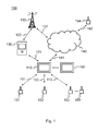
- Fig. 1 shows a schematic picture of a system 100 according to an example embodiment of the invention.
- the system 100 comprises an apparatus 110 configured to be capable of managing control devices 151-153, such as sensors, meters or switches.
- the apparatus 110 is configured to be connectable to the control devices over a data connection 111-113.
- the data connection 111-113 may be a wired connection or a wireless connection.
- the data connection 111-113 may comprise a mesh network, a point-to-point network or a bus network, for example.
- the wired connection may comprise Universal Serial Bus (USB), High-Definition Multimedia Interface (HDMI), M-bus, or local area network (LAN) such as Ethernet, for example.
- USB Universal Serial Bus
- HDMI High-Definition Multimedia Interface
- M-bus M-bus
- LAN local area network
- the wireless connection may comprise BluetoothTM, Radio Frequency Identification (RF-ID), Z-Wave, ZigBee, Infrared or wireless local area network (WLAN), for example.
- the system 100 may further comprise a second apparatus 110' configured to be capable of managing the control devices 151-153, such as sensors, meters or switches. The control apparatus 110 may hand over the control devices 151-153 to the second control apparatus 110'.
- the apparatus 110 is configured to send requests for control device data, controlling data or assignment/revocation information to the control devices 151-153.
- the control devices 151-153 are configured to send control device data, requests or assignment/revocation information to the apparatus 110.
- a user of the apparatus 110 may utilize a user interface of the apparatus 110 for communicating with the system 100, for example.
- the control devices 151-153 may also be configured to send control device data over the data connection 111-113 automatically to the apparatus 110. Such settings may comprise for example time of the day, amount of newly captured control device data or existence of the data connection 111-113 for the apparatus 110.
- the data communication between the apparatus 110 and the control devices 151-153 may also be triggered by a user of the apparatus 110 or a control process of the apparatus 110, for example.
- the system 100 comprises a remote control device 154 configured to be connectable to the apparatus 110 over a data connection 140-142.
- the data connection 140-142 may comprise any wired or wireless connection described for the connections 111-113 between the apparatus 110 and the control devices 151-153.
- the apparatus 110 and the remote control device 154 may be connected to a public data communication network 140, for example the Internet, over data connections 141 and 142, respectively.
- the user terminal 120 may comprise a mobile phone, an internet tablet or a laptop computer, for example.
- the user terminal 120 is capable of downloading and locally executing software program code.
- the software program code may be a client application of a service application running on the apparatus 110 of the system 100.
- the user terminal 120 is configured to be connectable to a wireless communication network 130 over a wireless connection 122.
- the wireless connection 122 may comprise a mobile cellular network or a wireless local area network (WLAN), for example.
- the wireless communication network 130 may be connected to a public data communication network 140, for example the Internet, over a data connection 131.
- the user terminal 120 is configured to be connectable to the apparatus 110 over a data connection 121.
- the data connection 121 may comprise any wired or wireless connection described for the connection 111-113 between the apparatus 110 and the control devices 151-153.
- the system 100 may utilize for any data connection 111-113, 121-122, 131, 140-142 wireless or wired technologies, in which control devices are not statically configured to the control system 100 but the control devices can also be included to and excluded from the control system 100 through similar kind of dynamic procedure like in wireless technologies discussed earlier in this application.
- control devices are not statically configured to the control system 100 but the control devices can also be included to and excluded from the control system 100 through similar kind of dynamic procedure like in wireless technologies discussed earlier in this application.
- Such systems are often internet protocol (IP) based and typically based on some special control protocol on top of the internet protocol (IP).
- the control devices that can be dynamically managed may comprise for example a sensor, an energy meter, a temperature meter, a humidity meter, a switch, a motion detector, a door opening/closing detector, a window opening/closing detector, and an input/output device.
- the control device 151-154 provides a set of services that the user can access through the control system 100 using the user interface of the apparatus 110 or the user terminal 120, for example.
- a switch device 151-154 may be considered to provide a switch service, which consists of the switch states 'on' and 'off' and corresponding functions defined for both states.
- One control device 151-154 may also provide multiple services.
- an energy-meter device 151-154 may provide a switch-service and an energy-meter service.
- the service concept may also enable the control system 100 to provide additional attributes and methods for the control device 151-154.
- the additional attributes and methods may comprise various kinds of calculations or statistics based on the control device data the control device 151-154 is able to provide.
- Such attributes and methods may comprise event logs, authentication and access control mechanisms, convenience attributes like nicknames and location data, for example. Characteristically, the additional attributes and methods may be implemented in the control system 100 with no or minimum involvement of the control device 151-154.
- FIG. 2 presents an example block diagram of a mesh network control system 200 in which various embodiments of the invention may be applied.
- a control apparatus 110 of the mesh network may comprise for example a laptop computer, a desktop computer, a tablet or a server computer apparatus.
- the control system 200 enables attaching of control devices 151-153 and services to the apparatus 110.
- the services may be implemented in the control apparatus 110 as service objects provided by an application layer 211. If the control device 151-153 is attached to the apparatus 110, the control device 151-153 may be assigned to the service object of the application layer 211 providing service functionality for the user.
- the mesh network 200 control apparatus 110 may further comprise a system controller 210.
- the system controller 210 incorporates a wireless technology specific network controller layer 213, an adaptation layer 212 and the application layer 211.
- the application layer 211 takes care of the service logic, as described above.
- the adaptation layer 212 may convert system controller 210 internal communication signals to wireless technology communication signals.
- the wireless technology controller layer 213 may incorporate wireless technology specific retransmissions.
- the wireless technology specific network layer 213 may take care of communication with the adaptation layer 212 and nodes 151-153 in the mesh network 200. It is technology specific how the node 151-153 is added to the mesh network 200. After the node 151-153 has been added and it is known to the system controller 210, configuration tasks may take place.
- the system controller 210 starts to execute set of tasks, inquiries and commands, which may be pre-configured or dynamic as the system controller 210 learns more about the node 151-153 introduced to the system 200.
- the set of tasks executed by the system controller 210 may be affected by the system controller capabilities.
- the system controller 210 may for example inquire device information, e.g. manufacturer, device type, serial number etc. The list above is not exhaustive.
- the system controller 210 may also set device configuration, for example message routing information or device wake-up interval if the device is battery operated and it turns on the radio within configured intervals for communication with wireless technology controller 213 or with other nodes 151-153 in the mesh network 200. For such battery operated devices the system controller can set a short wake-up signal that can be used as a task execution trigger.
- device configuration for example message routing information or device wake-up interval if the device is battery operated and it turns on the radio within configured intervals for communication with wireless technology controller 213 or with other nodes 151-153 in the mesh network 200.
- the system controller can set a short wake-up signal that can be used as a task execution trigger.
- the task execution trigger may comprise, instead of the wake-up signal, a triggering message indicating a device active state.
- triggering message may be user initiated or not and comprise, for example, a temperature value, a meter value and a door opening/closing signal.
- the control device 151-153 may send the triggering signal to be used as a task execution trigger.
- the device active state means that the control device radio is turned on and communication with the control device 151-153 is possible.
- the system controller 210 may select the next task and execute it right away. If the task fails, the system controller 210 may fall in "sleep state" for a length of period which can be pre-configured or dynamically decided. This way the system controller 210 may prevent congesting the mesh network 200, as in normal case the system controller 210 would try to execute the task again right away after the previous try failed. While the system controller 210 is in sleep state the mesh network 200 is available for other communication, for example energy meter device value reading. If the system controller 210 is in sleep state and a battery operated control device 151-153 that is under introduction wakes up, such wake up can be used as a trigger to continue task execution even though the sleep state period has not finished yet. This ensures faster device introduction.
- control device 151-153 with related services is ready to be used by the user of the apparatus 110.
- Task execution and task set finishing can be shown in the user interface of the apparatus 110 to reflect the progress, so that the end user knows status of the device introduction.
- user requests are delivered by the controller 210 to the desired service object of the application layer 211, which in turn communicates with the adaptation layer 212 before transmitting messages via the wireless technology layer 213 to the control device 151-153.
- Such communication may be utilized using a data connection 111-113.
- the data connection 111-113 may comprise for example Z-Wave in the mesh network 200.
- the control system 200 reduces congestion in the mesh network and enables reliable and user-friendly attaching of control devices 151-153 to the control apparatus 110.
- control device 151-153 comprises an energy meter of a rental holiday home and the service provided for the user is energy metering of a tenant living in the rental holiday home.
- the energy consumption of the tenant during her or his stay can be measured by assigning the energy meter to the tenant at the beginning of the stay and revoking the energy meter at the end of the stay.
- a control device 151 may comprise a switch
- a control device 152 may comprise a sensor
- a control device 153 may comprise a switch and an energy meter, for example.
- the control devices 151-153 are attached to the apparatus 110 by user request.
- the controller 210 informs service objects of the application layer 211. Based on the received information the service objects of the application layer 211 assign with corresponding control devices 151-153 using the configuration tasks created by the adaptation layer 212. Configuration messages provided by the adaptation layer 212 are transmitted to the corresponding control devices 151-153 using the wireless technology layer 213 messages. Thus the service objects of the application layer 211 are attached to the corresponding control devices 151-153.
- Switching energy mode as active/inactive may be carried out with the application layer objects based on user requests and communicating corresponding control data to the control device 151 comprising the switch.
- Measuring temperature may be carried out with another service object of the application layer 211 and metering energy consumption may be carried out with still another service object of the application layer 211 based on user requests and communicating corresponding control data to the control device 153 comprising the energy meter.
- Energy metering data from the control device 153 may be communicated over the data connection 113 per request or automatically, for example periodically.
- a single service object or application of the application layer 211 may also comprise a plurality of service objects or applications.
- At least one data connection 111-113 is based on Z-Wave technology.
- Z-Wave is a proprietary wireless communications protocol designed for home automation, specifically to remote control applications in residential and commercial environments.
- the technology uses a low-power radio embedded or retrofitted into electronic devices and systems, such as lightning, home access control, entertainment systems, and household appliances.
- Z-Wave communicates using a low-power wireless technology designed specifically for remote control applications.
- the Z-Wave wireless protocol is optimized for reliable and low-latency communication of small data packets, unlike typical wireless local area network systems that are designed primarily for high-bandwidth data flow.
- Z-Wave operates in the sub-gigahertz frequency range, around 900MHz. This band competes with some cordless telephones and other consumer electronics devices, but avoids interference systems that operate on the crowded 2.4GHz band.
- Z-Wave is designed to be easily embedded in consumer electronics products, including battery operated devices such as remote controls, smoke alarms and security sensors, for example.
- Z-Wave is a mesh networking technology, where each node or device 110, 151-153 on the network is capable of sending and receiving control commands through walls or floors and use intermediate nodes to route around household obstacles or radio dead spots that might occur in the home.
- Z-Wave devices like control devices 151-153 can work individually or in groups, and can be programmed into scenes or events that trigger multiple control devices 151-153, either automatically or via remote control.
- control system 200 it is possible to control and monitor for example household functions via remote control, based on manual or automated decisions.
- the control can be applied to a single control device 151-153 or to a group of control devices 151-153, in a single room, zone or throughout the entire building.
- Z-Wave control devices 151-153 can also be monitored and controlled from outside of the building by way of a gateway that combines Z-Wave with broadband Internet access, as showed in Fig. 1 .
- Z-Wave enabled thermostat 153 is able to raise or lower an indoor temperature of a building automatically, based on commands or sensor data from Z-Wave enabled daylight sensor 112. Grouped scene controls can ensure that unnecessary energy consumption is minimized by various all-off states for systems throughout the building, such as lightning, appliances and home entertainment systems.
- Z-Wave based system 200 can transceive commands based on real time conditions, and is able to control devices 151-153 in intelligent groupings, hence allowing novel extensions of traditional home security concepts.
- the opening of a Z-Wave enabled door lock 151-153 can deactivate a security system, turn on lights 151-153 when children arrive home from school, and send a notification to a parent's computer or cell phone via the Internet.
- Opening a Z-Wave enabled garage door 151-153 can trigger exterior and interior home lights, while a Z-Wave motion detector 151-153 can trigger an outdoor security light 151-153 and a webcam 151-153, which would allow the end user to monitor the home while away.
- Z-Wave's ability to command multiple control devices 151-153 as a unified event makes a system 200 well suited for home audio and video applications. For example, a simple "Play DVD" command on the remote control 110 could turn on the needed components 151-153, set them to the correct inputs and even lower motorized shades and dim the room lights.
- control system 200 may comprise a second control apparatus 110' as illustrated in Fig. 1 .
- the functional structure of the second control apparatus 110' corresponds to the structure of the control apparatus 110 provided in Fig. 2 .
- Fig. 3 presents an example block diagram of an apparatus 110 in which various embodiments of the invention may be applied.
- the apparatus 110 may be a laptop, a desktop, a tablet, a server computer or other computer apparatus.
- the general structure of the apparatus 110 comprises a user interface 340, a communication interface 350, a processor 310, and a memory 320 coupled to the processor 310.
- the apparatus 110 further comprises software 330 stored in the memory 320 and operable to be loaded into and executed in the processor 310.
- the software 330 may comprise one or more software modules and can be in the form of a computer program product.
- a service object, a service function, an application layer 211, an adaptation layer 212 and a wireless technology layer 213, may be comprised in the software modules.
- the apparatus 110 may further comprise a user interface controller 360.
- the processor 310 may be, e.g., a central processing unit (CPU), a microprocessor, a digital signal processor (DSP), a graphics processing unit, or the like.
- Fig. 3 shows one processor 310, but the apparatus 110 may comprise a plurality of processors.
- a controller 210 may be comprised by the processor 310.
- the memory 320 may be for example a non-volatile or a volatile memory, such as a read-only memory (ROM), a programmable read-only memory (PROM), erasable programmable read-only memory (EPROM), a random-access memory (RAM), a flash memory, a data disk, an optical storage, a magnetic storage, a smart card, or the like.
- the apparatus 110 may comprise a plurality of memories.
- the memory 320 may be constructed as a part of the apparatus 110 or it may be inserted into a slot, port, or the like of the user apparatus 110 by a user.
- the memory 320 may serve the sole purpose of storing data, or it may be constructed as a part of an apparatus serving other purposes, such as processing data.
- the user interface controller 360 may comprise circuitry for receiving input from a user of the apparatus 110, e.g., via a keyboard, graphical user interface shown on the display of the user interfaces 340 of the apparatus 110, speech recognition circuitry, or an accessory device, such as a headset, and for providing output to the user via, e.g., a graphical user interface or a loudspeaker.
- the communication interface module 350 implements at least part of data transmission.
- the communication interface module 350 may comprise, e.g., a wireless or a wired interface module.
- the wireless interface may comprise such as a WLAN, Z-Wave, Zigbee, BluetoothTM, Infrared (IR), Radio Frequency Identification (RF ID), GSM/GPRS, CDMA, WCDMA, or LTE (Long Term Evolution) radio module.
- the wired interface may comprise such as Universal Serial Bus (USB), Local Area Network (LAN) such as Ethernet or M-bus, for example.
- the communication interface module 350 may be integrated into the apparatus 110, or into an adapter, card or the like that may be inserted into a suitable slot or port of the apparatus 110.
- the communication interface module 350 may support one data interface technology or a plurality of technologies.
- the apparatus 110 may comprise a plurality of communication interface modules 350. Data communication between a device object and a control device may be transmitted using the communication interface 350. Furthermore, user communication data from a remote user terminal 120 may also be transmitted using the communication interface 350.
- the apparatus 110 may comprise other elements, such as microphones, extra displays, as well as additional circuitry such as input/output (I/O) circuitry, memory chips, application-specific integrated circuits (ASIC), processing circuitry for specific purposes such as source coding/decoding circuitry, channel coding/decoding circuitry, ciphering/deciphering circuitry, and the like. Additionally, the apparatus 110 may comprise a disposable or rechargeable battery (not shown) for powering when external power if external power supply is not available.
- I/O input/output
- ASIC application-specific integrated circuits
- processing circuitry for specific purposes such as source coding/decoding circuitry, channel coding/decoding circuitry, ciphering/deciphering circuitry, and the like.
- the apparatus 110 may comprise a disposable or rechargeable battery (not shown) for powering when external power if external power supply is not available.
- the system 100, 200 may comprise a second control apparatus 110' as illustrated in Fig. 1 .
- the block diagram of the second control apparatus 110' corresponds to the block diagram of the control apparatus 110 provided in Fig. 3 .
- Fig. 4 presents an example block diagram of a control device 400 in which various embodiments of the invention may be applied.
- the control device 400 may be a sensor, a switch or a meter, for example.
- the general structure of the control device 400 comprises a processor 410, and a memory 420 coupled to the processor 410.
- the control device 400 further comprises software 430 stored in the memory 420 and operable to be loaded into and executed in the processor 410.
- the software 430 may comprise one or more software modules and can be in the form of a computer program product.
- the processor 410 may be, e.g., a central processing unit (CPU), a microprocessor, a digital signal processor (DSP), a graphics processing unit, or the like.
- Fig. 4 shows one processor 410, but the control device 400 may comprise a plurality of processors.
- the memory 420 may be for example a non-volatile or a volatile memory, such as a read-only memory (ROM), a programmable read-only memory (PROM), erasable programmable read-only memory (EPROM), a random-access memory (RAM), a flash memory, a data disk, an optical storage, a magnetic storage, a smart card, or the like.
- the control device 400 may comprise a plurality of memories.
- the memory 420 may be constructed as a part of the control device 400 or it may be inserted into a slot, port, or the like of the control device 400 by a user.
- the memory 420 may serve the sole purpose of storing data, or it may be constructed as a part of an apparatus serving other purposes, such as processing data.
- the control device 400 may further comprise a sensor/switch/meter element 440 that may comprise a sensor, an energy meter, a temperature meter, a humidity meter, a switch, a motion detector, a door opening/closing detector, a window opening/closing detector, or an input/output device.
- a sensor/switch/meter element 440 may comprise a sensor, an energy meter, a temperature meter, a humidity meter, a switch, a motion detector, a door opening/closing detector, a window opening/closing detector, or an input/output device.
- the communication interface module 450 implements at least part of data transmission.
- the communication interface module 450 may comprise, e.g., a wireless or a wired interface module.
- the wireless interface may comprise such as a WLAN, Z-Wave, Zigbee, BluetoothTM, Infrared (IR), Radio Frequency Identification (RF ID), GSM/GPRS, CDMA, WCDMA, or LTE (Long Term Evolution) radio module.
- the wired interface may comprise such as Universal Serial Bus (USB), Local Area Network (LAN) such as Ethernet or M-bus, for example.
- the communication interface module 450 may be integrated into the control device 400, or into an adapter, card or the like that may be inserted into a suitable slot or port of the control device 400.
- the communication interface module 450 may support one data interface technology or a plurality of technologies.
- the control device 400 may comprise a plurality of communication interface modules 450. Data communication between a device object and a control device may be transmitted using the communication interface 450.
- control device 400 may comprise other elements, such as microphones, displays, as well as additional circuitry such as input/output (I/O) circuitry, memory chips, application-specific integrated circuits (ASIC), processing circuitry for specific purposes such as source coding/decoding circuitry, channel coding/decoding circuitry, ciphering/deciphering circuitry, and the like. Additionally, the control device 400 may comprise a disposable or rechargeable battery (not shown) for powering when external power if external power supply is not available
- Fig. 5 shows a flow diagram showing operations in accordance with an example embodiment of the invention.
- step 500 the method for attaching control devices to a control system in a mesh network is started.
- step 510 a control device is connected to an apparatus over the mesh network.
- step 520 at least one configuration task is defined for the control device. Based on the at least one configuration task, a configuration message is transmitted in an active state over the mesh network to the control device, in step 530.
- the apparatus is changed to an idle state, for a time period, in response to failing to receive a reply message from the control device, and releasing the mesh network for other communication.
- step 550 the apparatus is changed to the active state, in response to an expiration of the time period.
- the reply message is received from the control device over the mesh network in step 560 and the at least one configuration task is closed in response to the reply message from the control device, in step 570.
- the method is ended in step 580.
- Fig. 6 shows a flow diagram showing phases in accordance with an example embodiment of the invention. Attaching of a control device is first started in item 600. When the new control device is connected over a mesh network to the control system in item 610, the control system needs to recognize the control device in order to offer control device services to the end user via a user interface of an apparatus.
- the control device may provide a variety of services such as meters (energy meters, temperature meters, humidity meters, etc.), switches, motion detectors, door/window detectors, IO-devices etc. The list above is not exhaustive.
- the control system may also need to configure the control device, for example set message routing information or set some measurement rules such as a report-on-change temperature value. The list above is not exhaustive.
- the above procedures forms a task set of inquiries and commands that needs to be communicated with the control device during the control device introduction to the system.
- the task set is illustrated in item 670. Once the task set is finished, the services of the control device can be presented on the user interface and the end user can take the services in use.
- the task set may or may not be pre-configured, or it may even be dynamically formed during the introduction as the control system makes decisions which tasks to execute.
- At least one configuration task is defined and executed for the control device.
- the task may require a response from the control device, such as control device related information or acknowledgement.
- the control apparatus may transmit in an active state, based on the at least one configuration task, a configuration message over the mesh network, to the control device.
- the apparatus may determine if the control device responds until changing to idle state because of failing to complete the task, as illustrated in item 630.
- the control device may respond to the request with corrupted or incomplete response message that may lead to changing to idle state and failing to complete the task. Changing to idle state, for a time period, in response to failing to receive a reply message from the control device, enables releasing the mesh network for other communication between the control devices.
- the time period, or delay is illustrated, in which the system controlling apparatus may be changed to idle state and releasing the mesh network for other communication. The apparatus is then changed to the active state, in response to an expiration of the time period and the failed task may be executed again. In response to receiving a reply message from the control device over the mesh network and closing the task a further check is done.
- the control apparatus may check if further configuration tasks exist for the control device. If not, the procedure is ended 680 and the control device is successfully attached to the system and enabled to provide services to the user. If there are further configuration tasks to be done, a new task may be selected in item 660 from the task list 670 and proceeded to executing the task in item 620.
- the control system may retry to execute the task until it has been finished satisfactory way and thus improving reliability. Between the retries is the delay 640, in order not to congest the network.
- the delay 640 can be pre-configured or dynamic. If the execution of the task fails, the control system will not step over to next task until the current task has been finished satisfactory way. When the task is finished, the control system steps over to next task right away, thus providing fast task set execution if there is no problems in the communication between the control system and the device under introduction and attachment.
- a message in wireless mesh network can be lost or even corrupted due to various reasons. For example, overlapping networks interfere, attenuation due to distance between transmitting and receiving entities, reflection and distortion caused by building constructions, etc. Used communication technology may incorporate retransmission capability, but this does not necessary guarantee that communication between the control system and device under introduction will succeed.
- An adaptation layer of the system controller apparatus 110 may convert system controller internal communication method to the wireless technology communication methods.
- Wireless technology controller layer may incorporate wireless technology specific retransmissions.
- Different embodiments may be implemented in adaptation layer with for example threads or processes.
- Wireless technology layer of the system controller apparatus 110 may take care of communication with adaptation layer and nodes in the mesh network. It is technology specific how the node is added to the mesh network. After node has been added and it is known to the system controller 210, configuration tasks may be executed.
- the system controller 210 may also set control device 151-153, 400 configuration, for example message routing information or device wake-up interval if the control device 151-153, 400 is battery operated.
- the control device 151-153, 400 may turn on the radio on configured intervals for communication with the wireless technology controller 213 of the system controller apparatus 110 or with other nodes in the mesh network.
- the system controller apparatus 110 may set a wake-up signal that can be used as a task execution trigger.
- the wake-up signal is also illustrated in item 620.
- the wake-up signal for the task execution 620 may comprise a message indicating an active state of the control device 151-153, 400.
- Such message may comprise, for example, a temperature value, a meter value or a door opening/closing status.
- the control device 151-153, 400 may send the message to the system controller apparatus 110 and the message can be used as the wake-up signal for the task execution 620.
- the active state of the control device 151-153, 400 typically means that the communication interface 450 (e.g. radio) is active and communication with the control device 151-153, 400 is possible.
- the system controller apparatus 110 selects next task and executes it right away. If task fails, the system controller apparatus 110 falls in sleep/idle state for a length of period which can be pre-configured or dynamically decided. This way the system controller apparatus 110 prevents congesting the mesh network, as in opposed case the system controller apparatus 110 would try to execute task again right away after previous try failed. While the system controller apparatus 110 is in sleep/idle state the mesh network is available for other communication, for example energy meter device value reading.
- the wake-up signal can be used as a trigger to continue task execution in item 620 even though the sleep/idle state period has not finished yet. This ensures faster device introduction.
- any message indicating the control device 151-153, 400 is in active state may be used.
- Such active state of the control device 151-153, 400 typically means that the communication interface 450 (e.g. radio) is active and communication with the control device 151-153, 400 is possible.
- control device attachment is ready and the control device and services offered are ready to be used.
- Task execution and task set finishing can be shown on the user interface of the system controller apparatus to reflect the progress, so that the end user knows status of the control device introduction.
- Different embodiments may provide a smart and reliable logic that ensures that the mesh network control device under introduction will be recognized and configured properly so that all the offered control device services can be properly used.
- the time how quickly the control device is ready to be used from the point device introduction started till the task set completion depends on the sleep state delay length, the number of executed tasks and the number of used retries. Both parameters may be defined by the system controller apparatus or the user.
- a first system controller apparatus 110 may hand over the control devices 151-153, 400 to a second system controller apparatus 110'.
- the second system controller apparatus then may need to interrogate and/or configure the control devices 151-153, 400 in order to enable services provided by the control devices 151-153, 400.
- a first system controller 210 may transfer an initial set of control device identification information to a second system controller of the second system controller apparatus 110'. Such transfer may be utilized by the wireless technology layer of the system controllers, for example.
- the second system controller apparatus 110' may utilize configuration and route setting between the second controller apparatus 110' and the control devices 151-153, 400 to identify, configure and present the services provided by the control devices 151-153, 400 for the user. Such configuration and route setting may be utilized by the adaptation layer of the system controllers, for example.
Landscapes
- Engineering & Computer Science (AREA)
- Computer Networks & Wireless Communication (AREA)
- Signal Processing (AREA)
- Selective Calling Equipment (AREA)
- Mobile Radio Communication Systems (AREA)
- Telephonic Communication Services (AREA)
Applications Claiming Priority (1)
| Application Number | Priority Date | Filing Date | Title |
|---|---|---|---|
| FI20125258A FI124519B (en) | 2012-03-12 | 2012-03-12 | A method of connecting control devices to a control system in a mesh network |
Publications (2)
| Publication Number | Publication Date |
|---|---|
| EP2640137A1 true EP2640137A1 (fr) | 2013-09-18 |
| EP2640137B1 EP2640137B1 (fr) | 2015-03-04 |
Family
ID=47912956
Family Applications (1)
| Application Number | Title | Priority Date | Filing Date |
|---|---|---|---|
| EP13158134.0A Not-in-force EP2640137B1 (fr) | 2012-03-12 | 2013-03-07 | Procédé pour fixer des dispositifs de commande pour système de commande en réseau maillé |
Country Status (2)
| Country | Link |
|---|---|
| EP (1) | EP2640137B1 (fr) |
| FI (1) | FI124519B (fr) |
Cited By (1)
| Publication number | Priority date | Publication date | Assignee | Title |
|---|---|---|---|---|
| CN107070690A (zh) * | 2017-01-02 | 2017-08-18 | 美科科技(北京)有限公司 | 用于电子模块的组网核心装置、无线组网方法和基于电子模块的智能网络系统 |
Citations (3)
| Publication number | Priority date | Publication date | Assignee | Title |
|---|---|---|---|---|
| WO2005048472A2 (fr) * | 2003-11-12 | 2005-05-26 | Interdigital Technology Corporation | Procede et systeme de communication sans fil permettant de gerer l'association et la desassociation d'une unite d'emission/reception sans fil |
| US20100008276A1 (en) * | 2008-07-11 | 2010-01-14 | Milind Kopikare | Power save mode for access points |
| WO2011124853A1 (fr) * | 2010-04-08 | 2011-10-13 | France Telecom | Procede de controle d'un point d'acces d'une passerelle domestique d'un reseau domestique |
-
2012
- 2012-03-12 FI FI20125258A patent/FI124519B/en not_active IP Right Cessation
-
2013
- 2013-03-07 EP EP13158134.0A patent/EP2640137B1/fr not_active Not-in-force
Patent Citations (3)
| Publication number | Priority date | Publication date | Assignee | Title |
|---|---|---|---|---|
| WO2005048472A2 (fr) * | 2003-11-12 | 2005-05-26 | Interdigital Technology Corporation | Procede et systeme de communication sans fil permettant de gerer l'association et la desassociation d'une unite d'emission/reception sans fil |
| US20100008276A1 (en) * | 2008-07-11 | 2010-01-14 | Milind Kopikare | Power save mode for access points |
| WO2011124853A1 (fr) * | 2010-04-08 | 2011-10-13 | France Telecom | Procede de controle d'un point d'acces d'une passerelle domestique d'un reseau domestique |
Cited By (2)
| Publication number | Priority date | Publication date | Assignee | Title |
|---|---|---|---|---|
| CN107070690A (zh) * | 2017-01-02 | 2017-08-18 | 美科科技(北京)有限公司 | 用于电子模块的组网核心装置、无线组网方法和基于电子模块的智能网络系统 |
| CN107070690B (zh) * | 2017-01-02 | 2020-12-22 | 美科科技(北京)有限公司 | 用于电子模块的组网核心装置、无线组网方法和基于电子模块的智能网络系统 |
Also Published As
| Publication number | Publication date |
|---|---|
| FI124519B (en) | 2014-09-30 |
| EP2640137B1 (fr) | 2015-03-04 |
| FI20125258A (fi) | 2013-09-13 |
Similar Documents
| Publication | Publication Date | Title |
|---|---|---|
| US10943470B2 (en) | Method and apparatus for controlling a home device remotely in a home network system | |
| US11324074B2 (en) | Mesh network system comprising a plurality of interconnected individual mesh networks | |
| RU2676229C1 (ru) | Эффективная связь для устройств домашней сети | |
| US9913352B2 (en) | System and method for light socket adaptation | |
| CA2661915C (fr) | Procede et dispositif de liaison dans un systeme d'automatisation de construction | |
| US20220239622A1 (en) | Efficient Network Stack for Wireless Application Protocols | |
| EP2706733A1 (fr) | Procédé pour suspendre le trafic dans un système de commande de réseau maillé | |
| US20180316446A1 (en) | Method, device, and system for management and communication of a wireless mesh network | |
| EP3053369B1 (fr) | Procédé et appareil de mise en service inter-profile dans un réseau | |
| US20150268670A1 (en) | Wireless apparatus, system, and method for controlling a valve | |
| EP2181528B1 (fr) | Système de communication | |
| US9281958B2 (en) | Method for providing interworking service in home network | |
| US10841166B2 (en) | Commissioning and personalizing devices in a local area network | |
| Paetz | Z-Wave Essentials | |
| US10489055B2 (en) | Z-wave controller shift in thermostats | |
| KR101573785B1 (ko) | Z-Wave 네트워크를 이용한 홈네트워크 시스템 및 그 시스템을 이용한 홈오토메이션 기기 연결 방법 | |
| EP2640137B1 (fr) | Procédé pour fixer des dispositifs de commande pour système de commande en réseau maillé | |
| EP2639663A2 (fr) | Système, procédé et dispositif pour la gestion dynamique des dispositifs de commande | |
| EP3860082A1 (fr) | Système de réseau maillé comprenant une pluralité de réseaux maillés individuels interconnectés | |
| US20200044888A1 (en) | Smart home system | |
| KR20200023719A (ko) | WiFi 기반 통합 리모컨 및 그를 이용한 사물인터넷 제어 시스템 |
Legal Events
| Date | Code | Title | Description |
|---|---|---|---|
| PUAI | Public reference made under article 153(3) epc to a published international application that has entered the european phase |
Free format text: ORIGINAL CODE: 0009012 |
|
| AK | Designated contracting states |
Kind code of ref document: A1 Designated state(s): AL AT BE BG CH CY CZ DE DK EE ES FI FR GB GR HR HU IE IS IT LI LT LU LV MC MK MT NL NO PL PT RO RS SE SI SK SM TR |
|
| AX | Request for extension of the european patent |
Extension state: BA ME |
|
| 17P | Request for examination filed |
Effective date: 20140226 |
|
| RBV | Designated contracting states (corrected) |
Designated state(s): AL AT BE BG CH CY CZ DE DK EE ES FI FR GB GR HR HU IE IS IT LI LT LU LV MC MK MT NL NO PL PT RO RS SE SI SK SM TR |
|
| GRAP | Despatch of communication of intention to grant a patent |
Free format text: ORIGINAL CODE: EPIDOSNIGR1 |
|
| INTG | Intention to grant announced |
Effective date: 20140917 |
|
| GRAS | Grant fee paid |
Free format text: ORIGINAL CODE: EPIDOSNIGR3 |
|
| GRAA | (expected) grant |
Free format text: ORIGINAL CODE: 0009210 |
|
| AK | Designated contracting states |
Kind code of ref document: B1 Designated state(s): AL AT BE BG CH CY CZ DE DK EE ES FI FR GB GR HR HU IE IS IT LI LT LU LV MC MK MT NL NO PL PT RO RS SE SI SK SM TR |
|
| REG | Reference to a national code |
Ref country code: GB Ref legal event code: FG4D |
|
| REG | Reference to a national code |
Ref country code: CH Ref legal event code: EP |
|
| REG | Reference to a national code |
Ref country code: IE Ref legal event code: FG4D |
|
| REG | Reference to a national code |
Ref country code: AT Ref legal event code: REF Ref document number: 714764 Country of ref document: AT Kind code of ref document: T Effective date: 20150415 |
|
| REG | Reference to a national code |
Ref country code: DE Ref legal event code: R096 Ref document number: 602013001025 Country of ref document: DE Effective date: 20150416 |
|
| REG | Reference to a national code |
Ref country code: AT Ref legal event code: MK05 Ref document number: 714764 Country of ref document: AT Kind code of ref document: T Effective date: 20150304 Ref country code: NL Ref legal event code: VDEP Effective date: 20150304 |
|
| PG25 | Lapsed in a contracting state [announced via postgrant information from national office to epo] |
Ref country code: NO Free format text: LAPSE BECAUSE OF FAILURE TO SUBMIT A TRANSLATION OF THE DESCRIPTION OR TO PAY THE FEE WITHIN THE PRESCRIBED TIME-LIMIT Effective date: 20150604 Ref country code: SE Free format text: LAPSE BECAUSE OF FAILURE TO SUBMIT A TRANSLATION OF THE DESCRIPTION OR TO PAY THE FEE WITHIN THE PRESCRIBED TIME-LIMIT Effective date: 20150304 Ref country code: ES Free format text: LAPSE BECAUSE OF FAILURE TO SUBMIT A TRANSLATION OF THE DESCRIPTION OR TO PAY THE FEE WITHIN THE PRESCRIBED TIME-LIMIT Effective date: 20150304 Ref country code: LT Free format text: LAPSE BECAUSE OF FAILURE TO SUBMIT A TRANSLATION OF THE DESCRIPTION OR TO PAY THE FEE WITHIN THE PRESCRIBED TIME-LIMIT Effective date: 20150304 Ref country code: HR Free format text: LAPSE BECAUSE OF FAILURE TO SUBMIT A TRANSLATION OF THE DESCRIPTION OR TO PAY THE FEE WITHIN THE PRESCRIBED TIME-LIMIT Effective date: 20150304 Ref country code: FI Free format text: LAPSE BECAUSE OF FAILURE TO SUBMIT A TRANSLATION OF THE DESCRIPTION OR TO PAY THE FEE WITHIN THE PRESCRIBED TIME-LIMIT Effective date: 20150304 |
|
| REG | Reference to a national code |
Ref country code: LT Ref legal event code: MG4D |
|
| PG25 | Lapsed in a contracting state [announced via postgrant information from national office to epo] |
Ref country code: LV Free format text: LAPSE BECAUSE OF FAILURE TO SUBMIT A TRANSLATION OF THE DESCRIPTION OR TO PAY THE FEE WITHIN THE PRESCRIBED TIME-LIMIT Effective date: 20150304 Ref country code: AT Free format text: LAPSE BECAUSE OF FAILURE TO SUBMIT A TRANSLATION OF THE DESCRIPTION OR TO PAY THE FEE WITHIN THE PRESCRIBED TIME-LIMIT Effective date: 20150304 Ref country code: RS Free format text: LAPSE BECAUSE OF FAILURE TO SUBMIT A TRANSLATION OF THE DESCRIPTION OR TO PAY THE FEE WITHIN THE PRESCRIBED TIME-LIMIT Effective date: 20150304 Ref country code: GR Free format text: LAPSE BECAUSE OF FAILURE TO SUBMIT A TRANSLATION OF THE DESCRIPTION OR TO PAY THE FEE WITHIN THE PRESCRIBED TIME-LIMIT Effective date: 20150605 |
|
| PG25 | Lapsed in a contracting state [announced via postgrant information from national office to epo] |
Ref country code: NL Free format text: LAPSE BECAUSE OF FAILURE TO SUBMIT A TRANSLATION OF THE DESCRIPTION OR TO PAY THE FEE WITHIN THE PRESCRIBED TIME-LIMIT Effective date: 20150304 |
|
| PG25 | Lapsed in a contracting state [announced via postgrant information from national office to epo] |
Ref country code: SK Free format text: LAPSE BECAUSE OF FAILURE TO SUBMIT A TRANSLATION OF THE DESCRIPTION OR TO PAY THE FEE WITHIN THE PRESCRIBED TIME-LIMIT Effective date: 20150304 Ref country code: CZ Free format text: LAPSE BECAUSE OF FAILURE TO SUBMIT A TRANSLATION OF THE DESCRIPTION OR TO PAY THE FEE WITHIN THE PRESCRIBED TIME-LIMIT Effective date: 20150304 Ref country code: RO Free format text: LAPSE BECAUSE OF FAILURE TO SUBMIT A TRANSLATION OF THE DESCRIPTION OR TO PAY THE FEE WITHIN THE PRESCRIBED TIME-LIMIT Effective date: 20150304 Ref country code: EE Free format text: LAPSE BECAUSE OF FAILURE TO SUBMIT A TRANSLATION OF THE DESCRIPTION OR TO PAY THE FEE WITHIN THE PRESCRIBED TIME-LIMIT Effective date: 20150304 Ref country code: PT Free format text: LAPSE BECAUSE OF FAILURE TO SUBMIT A TRANSLATION OF THE DESCRIPTION OR TO PAY THE FEE WITHIN THE PRESCRIBED TIME-LIMIT Effective date: 20150706 |
|
| PG25 | Lapsed in a contracting state [announced via postgrant information from national office to epo] |
Ref country code: IS Free format text: LAPSE BECAUSE OF FAILURE TO SUBMIT A TRANSLATION OF THE DESCRIPTION OR TO PAY THE FEE WITHIN THE PRESCRIBED TIME-LIMIT Effective date: 20150704 Ref country code: PL Free format text: LAPSE BECAUSE OF FAILURE TO SUBMIT A TRANSLATION OF THE DESCRIPTION OR TO PAY THE FEE WITHIN THE PRESCRIBED TIME-LIMIT Effective date: 20150304 |
|
| REG | Reference to a national code |
Ref country code: DE Ref legal event code: R097 Ref document number: 602013001025 Country of ref document: DE |
|
| PG25 | Lapsed in a contracting state [announced via postgrant information from national office to epo] |
Ref country code: IT Free format text: LAPSE BECAUSE OF FAILURE TO SUBMIT A TRANSLATION OF THE DESCRIPTION OR TO PAY THE FEE WITHIN THE PRESCRIBED TIME-LIMIT Effective date: 20150304 |
|
| PLBE | No opposition filed within time limit |
Free format text: ORIGINAL CODE: 0009261 |
|
| STAA | Information on the status of an ep patent application or granted ep patent |
Free format text: STATUS: NO OPPOSITION FILED WITHIN TIME LIMIT |
|
| REG | Reference to a national code |
Ref country code: IE Ref legal event code: MM4A |
|
| PG25 | Lapsed in a contracting state [announced via postgrant information from national office to epo] |
Ref country code: MC Free format text: LAPSE BECAUSE OF FAILURE TO SUBMIT A TRANSLATION OF THE DESCRIPTION OR TO PAY THE FEE WITHIN THE PRESCRIBED TIME-LIMIT Effective date: 20150304 Ref country code: IE Free format text: LAPSE BECAUSE OF NON-PAYMENT OF DUE FEES Effective date: 20150307 Ref country code: DK Free format text: LAPSE BECAUSE OF FAILURE TO SUBMIT A TRANSLATION OF THE DESCRIPTION OR TO PAY THE FEE WITHIN THE PRESCRIBED TIME-LIMIT Effective date: 20150304 |
|
| 26N | No opposition filed |
Effective date: 20151207 |
|
| PG25 | Lapsed in a contracting state [announced via postgrant information from national office to epo] |
Ref country code: SI Free format text: LAPSE BECAUSE OF FAILURE TO SUBMIT A TRANSLATION OF THE DESCRIPTION OR TO PAY THE FEE WITHIN THE PRESCRIBED TIME-LIMIT Effective date: 20150304 |
|
| REG | Reference to a national code |
Ref country code: FR Ref legal event code: PLFP Year of fee payment: 4 |
|
| PG25 | Lapsed in a contracting state [announced via postgrant information from national office to epo] |
Ref country code: BE Free format text: LAPSE BECAUSE OF FAILURE TO SUBMIT A TRANSLATION OF THE DESCRIPTION OR TO PAY THE FEE WITHIN THE PRESCRIBED TIME-LIMIT Effective date: 20150304 |
|
| REG | Reference to a national code |
Ref country code: CH Ref legal event code: PL |
|
| PG25 | Lapsed in a contracting state [announced via postgrant information from national office to epo] |
Ref country code: MT Free format text: LAPSE BECAUSE OF FAILURE TO SUBMIT A TRANSLATION OF THE DESCRIPTION OR TO PAY THE FEE WITHIN THE PRESCRIBED TIME-LIMIT Effective date: 20150304 |
|
| PG25 | Lapsed in a contracting state [announced via postgrant information from national office to epo] |
Ref country code: CH Free format text: LAPSE BECAUSE OF NON-PAYMENT OF DUE FEES Effective date: 20160331 Ref country code: LI Free format text: LAPSE BECAUSE OF NON-PAYMENT OF DUE FEES Effective date: 20160331 |
|
| REG | Reference to a national code |
Ref country code: FR Ref legal event code: PLFP Year of fee payment: 5 |
|
| PGFP | Annual fee paid to national office [announced via postgrant information from national office to epo] |
Ref country code: DE Payment date: 20170322 Year of fee payment: 5 Ref country code: FR Payment date: 20170322 Year of fee payment: 5 |
|
| PG25 | Lapsed in a contracting state [announced via postgrant information from national office to epo] |
Ref country code: HU Free format text: LAPSE BECAUSE OF FAILURE TO SUBMIT A TRANSLATION OF THE DESCRIPTION OR TO PAY THE FEE WITHIN THE PRESCRIBED TIME-LIMIT; INVALID AB INITIO Effective date: 20130307 Ref country code: BG Free format text: LAPSE BECAUSE OF FAILURE TO SUBMIT A TRANSLATION OF THE DESCRIPTION OR TO PAY THE FEE WITHIN THE PRESCRIBED TIME-LIMIT Effective date: 20150304 |
|
| PGFP | Annual fee paid to national office [announced via postgrant information from national office to epo] |
Ref country code: GB Payment date: 20170322 Year of fee payment: 5 |
|
| PG25 | Lapsed in a contracting state [announced via postgrant information from national office to epo] |
Ref country code: CY Free format text: LAPSE BECAUSE OF FAILURE TO SUBMIT A TRANSLATION OF THE DESCRIPTION OR TO PAY THE FEE WITHIN THE PRESCRIBED TIME-LIMIT Effective date: 20150304 |
|
| PG25 | Lapsed in a contracting state [announced via postgrant information from national office to epo] |
Ref country code: TR Free format text: LAPSE BECAUSE OF FAILURE TO SUBMIT A TRANSLATION OF THE DESCRIPTION OR TO PAY THE FEE WITHIN THE PRESCRIBED TIME-LIMIT Effective date: 20150304 |
|
| PG25 | Lapsed in a contracting state [announced via postgrant information from national office to epo] |
Ref country code: LU Free format text: LAPSE BECAUSE OF NON-PAYMENT OF DUE FEES Effective date: 20150307 |
|
| PG25 | Lapsed in a contracting state [announced via postgrant information from national office to epo] |
Ref country code: SM Free format text: LAPSE BECAUSE OF FAILURE TO SUBMIT A TRANSLATION OF THE DESCRIPTION OR TO PAY THE FEE WITHIN THE PRESCRIBED TIME-LIMIT Effective date: 20150304 |
|
| PG25 | Lapsed in a contracting state [announced via postgrant information from national office to epo] |
Ref country code: MK Free format text: LAPSE BECAUSE OF FAILURE TO SUBMIT A TRANSLATION OF THE DESCRIPTION OR TO PAY THE FEE WITHIN THE PRESCRIBED TIME-LIMIT Effective date: 20150304 |
|
| REG | Reference to a national code |
Ref country code: DE Ref legal event code: R119 Ref document number: 602013001025 Country of ref document: DE |
|
| PG25 | Lapsed in a contracting state [announced via postgrant information from national office to epo] |
Ref country code: AL Free format text: LAPSE BECAUSE OF FAILURE TO SUBMIT A TRANSLATION OF THE DESCRIPTION OR TO PAY THE FEE WITHIN THE PRESCRIBED TIME-LIMIT Effective date: 20150304 |
|
| GBPC | Gb: european patent ceased through non-payment of renewal fee |
Effective date: 20180307 |
|
| PG25 | Lapsed in a contracting state [announced via postgrant information from national office to epo] |
Ref country code: DE Free format text: LAPSE BECAUSE OF NON-PAYMENT OF DUE FEES Effective date: 20181002 |
|
| PG25 | Lapsed in a contracting state [announced via postgrant information from national office to epo] |
Ref country code: GB Free format text: LAPSE BECAUSE OF NON-PAYMENT OF DUE FEES Effective date: 20180307 |
|
| PG25 | Lapsed in a contracting state [announced via postgrant information from national office to epo] |
Ref country code: FR Free format text: LAPSE BECAUSE OF NON-PAYMENT OF DUE FEES Effective date: 20180331 |