EP2640020A1 - Detection and correction of a routing loop in a network of routers using an SPF routing protocol - Google Patents
Detection and correction of a routing loop in a network of routers using an SPF routing protocol Download PDFInfo
- Publication number
- EP2640020A1 EP2640020A1 EP12305306.8A EP12305306A EP2640020A1 EP 2640020 A1 EP2640020 A1 EP 2640020A1 EP 12305306 A EP12305306 A EP 12305306A EP 2640020 A1 EP2640020 A1 EP 2640020A1
- Authority
- EP
- European Patent Office
- Prior art keywords
- router
- routers
- destination
- network
- routing
- Prior art date
- Legal status (The legal status is an assumption and is not a legal conclusion. Google has not performed a legal analysis and makes no representation as to the accuracy of the status listed.)
- Granted
Links
Images


Classifications
-
- H—ELECTRICITY
- H04—ELECTRIC COMMUNICATION TECHNIQUE
- H04L—TRANSMISSION OF DIGITAL INFORMATION, e.g. TELEGRAPHIC COMMUNICATION
- H04L45/00—Routing or path finding of packets in data switching networks
- H04L45/18—Loop-free operations
-
- H—ELECTRICITY
- H04—ELECTRIC COMMUNICATION TECHNIQUE
- H04L—TRANSMISSION OF DIGITAL INFORMATION, e.g. TELEGRAPHIC COMMUNICATION
- H04L45/00—Routing or path finding of packets in data switching networks
- H04L45/02—Topology update or discovery
- H04L45/03—Topology update or discovery by updating link state protocols
-
- H—ELECTRICITY
- H04—ELECTRIC COMMUNICATION TECHNIQUE
- H04L—TRANSMISSION OF DIGITAL INFORMATION, e.g. TELEGRAPHIC COMMUNICATION
- H04L45/00—Routing or path finding of packets in data switching networks
- H04L45/28—Routing or path finding of packets in data switching networks using route fault recovery
Definitions
- the present invention generally relates to network routers using a "short-path first" link-state dynamic routing protocol, also known as Shortest Path First SPF protocol.
- OSPF Open Shortest Path First
- RFC2328 This link-state dynamic routing protocol makes it possible to establish routing tables for a network of routers according to the state of the links (or links) between the routers of the network.
- OSPF recognition of the link state between routers allows a router that needs to send data to a given destination to choose the route with the best overall bandwidth, even if it does not. This is not the shortest route in metric jump number (or router) that separates the sending router from the destination router.
- the state of a link between two routers corresponds to a cost which is a number determined according to the data rate available between said routers. The higher the available bit rate, the lower the cost, for example 1, and the lower the bit rate the higher the cost, for example 10.
- the cost of a route is calculated by adding the costs of the links that connect them the successive routers of this road.
- routers flood the state of their links, that is, the state of their network interfaces, with neighboring routers in the form of packets called LSAs (for Link State Advertisement that can be translated by ads of the status of links in French).
- LSAs Link State Advertisement
- Each router thus has a LSA table, called LSDB (Link State Database in English), which allows it to know the link status between each pair of network routers.
- the Dijkstra SPF algorithm is then applied to this LSDB table to compute a routing table for each source router.
- the routing table is a list of neighboring routers, called "next hop", to which the data packet must be transmitted according to the destination to be reached.
- the routing table obtained contains the shortest routes in terms of cost that make it possible to reach the different routers of the network from this source router.
- Dijkstra's SPF route calculation also called the shortest path algorithm first, is detailed in section 16 of RFC2328.
- the RFC3623 When restarting a router, the RFC3623 provides a mechanism for improving the OSPF routing protocol by which the restarting router can continue to pass data to a given destination, even if the control function of the routing table of this router is restarted. This mechanism is called the OSPF restart mechanism (OSPF graceful-restart) or the OSPF restart with uninterrupted transmission.
- OSPF restart mechanism OSPF graceful-restart
- the data transmission function of the restarting router can remain active, even if the associated control function is no longer available due to the restart of the router, which allows the restarting router to continue transmitting data in accordance with its routing table remains frozen as the router restarts.
- Such a mechanism prevents network routers from having to recalculate all their routing tables to bypass the router being restarted, which would effectively remove the router from the topology, and thus stop sending traffic to it. .
- the impact of the restart of the router on the data traffic of the network is thus reduced.
- the restarting router can not take into account this change since it can not update its routing table and there is a risk of occurrence of loop (s) routing.
- the RFC3623 recommends interrupting the restart mechanism in the traffic continuity mode of said router.
- the router then restarts in a conventional manner while being removed from the topology of the network so that it is no longer visible by the other routers during its restart.
- the other routers in the network recalculate the new routes following this change of topology to reconverge the network, which can slow down the traffic in the network.
- a topology change does not necessarily result in a routing loop when a router restarts in traffic continuity mode.
- said SPF type protocol is the OSPF protocol.
- the routers which in the destination graph of the destination router at risk are part of a route of access to the destination router at risk, have a minimum number of redirects equal to 0.
- the redirection order of said routers to be redirected is the increasing order of their number of redirects.
- the router redirection step is not performed and the restart in traffic continuity mode. restarting router is stopped. In this case, the restarting router is removed from the network topology and the other routers recalculate their routing table according to the new topology.
- the redirected routers are redirected back to their original successor router in descending order of their number of redirects.
- the link state data between said router and the neighboring routers of said router are updated, as well as the routing table of said router.
- the routing table or tables of the routers redirected to reach the first risk router are also modified to reach the second router at risk.
- a network of routers configured to use a routing protocol a link state type dynamic, called SPF protocol, said routers being configured to detect at least one destination that may generate a routing loop according to a loop detection method as described above.
- SPF protocol link state type dynamic
- a network of routers configured to correct said at least one routing loop according to a loop correction method as described above.
- inventions also relate to a computer program comprising program code instructions for performing the steps of a method as described above, when said program is run on a computer.
- various embodiments of the invention propose a method and a network of corresponding routers for detecting a routing loop in a network of routers that uses a dynamic link state routing protocol.
- This routing protocol makes it possible to determine the shortest routes according to the state of the links between the routers.
- Such a routing protocol is usually called SPF protocol for "Shortest Path First" in English.
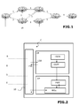
- the figure 1 is a schematic view of a network of routers A, B, C, D, E, F, G.
- a connection between two routers is represented by two arrows in opposite directions.
- the direction of an arrow indicates the direction of communication and the number associated with this arrow represents the link state of this communication.
- the arrows are also referred to as connecting arcs.
- the link state between two routers corresponds to a cost which is a number determined according to the data rate available between said routers. The higher the available bit rate, the lower the cost, for example 1, and the lower the bit rate the higher the cost, for example 10.
- the cost of a route is calculated by adding the costs of the links that connect them the successive routers of this road.
- the figure 2 schematizes the functional modules of a typical router of the network of the figure 1 for example the router C interfaced with other routers, here routers A, B, D and E.
- the typical router schematized at the figure 2 includes an electronic and computer system for performing two physically distinct functions.
- One of these functions is a CP (Control Plane) control function for transmitting link state data (LSAs) generated by said router and receiving the LSAs of the other routers to form a table of LSAs. , named LSDB.
- the CP control function also makes it possible, by using the LSDB table, and the Dijkstra routing algorithm of the OSPF protocol, to calculate the shortest routes in terms of cost to reach each destination of the network.
- the other function is a DP (Data Plane) data transmission function which comprises data transmission modules, denoted PFEs (for Packet Forwarding Engine in English), configured to transmit data to their destination according to the routes. calculated by the control function CP and stored in a routing table FWT (for Forwarding Table in English).
- the FWT routing table used by the PFEs data transmission modules is intended to be updated by the control function CP.
- said LSAs and the data to be transmitted are exchanged between the router C and the neighboring routers A, B, DE with the aid of a set of connection interfaces 10 with said neighboring routers A, B, D E.
- the topology of the network illustrated in figure 1 corresponds to an initial topology of the network, before restarting the router C in traffic continuity mode.
- the restart in traffic continuity mode of a router for example the router C, as proposed in RFC3623 which is fully incorporated by reference in the description, makes it possible to restart the CP control function of the router. C, while maintaining the DP data transmission function which continues to transmit the data packets to the successor routers indicated in its FWT routing table which remains frozen during the restart.
- the router C which restarts in traffic continuity mode generates and transmits to its neighboring routers A, B, D, E, called assistant routers, specific link state packets LSAs, called Grace-LSA that indicate to neighboring routers a grace period during which the control function of the restarting router's routing table is no longer active.
- the assistant routers continue to transmit LSAs to the other routers to indicate that the restarting router C is still present.
- the routing table of the restarting router can not be modified during the restart and therefore remains frozen during this restart in the state where it was just before the restart, that is to say in agreement with the initial topology illustrated at figure 1 .
- the figure 3 illustrates a network topology change while router C is restarting in traffic continuity mode. Indeed, while the router C restarts, the connection is broken between the router D and the router F. The router D then recalculates the shortest routes in terms of cost that allow it to reach the other routers. Thus, from the point of view of the router D, the shortest route to reach the router F becomes D-> B -> C ->E-> F. Thus, the router D replaces in its routing table its successor router F initial by successor router B with respect to destination F.
- routers A, B, D, E, F, G can update their routing table to account for the new topology of the figure 3
- the routing table of the router C which restarts remains fixed in the state of the initial topology of the network as illustrated in FIG. figure 1 .
- the router C which receives from the router B a packet to the router F transmits it to its successor router as defined in its fixed routing table, namely the router D.
- the shortest route to transmit from the router C data to the router F is the route C->D-> F
- the shortest route becomes the road C->E-> F.
- a change of topology does not necessarily lead to the appearance of a routing loop. It is therefore important to be able to detect if the network comprises one or more destinations for which there is a routing loop.
- the flow diagram of the figure 4 is an exemplary embodiment of a method for detecting such a routing loop.
- step 101 the source graph G C of router C is determined based on the initial topology of the network. This source graph G C of the router C is represented at figure 7 .
- the source graph of a router corresponds to the shortest routes according to the SPF protocol, here the OSPF protocol, which leave the source router to reach the other routers of the network.
- a destination graph of a router corresponds to the shortest paths according to the SPF protocol, here the OSPF protocol, which depart from the other routers of the network to reach said destination router.
- the restarting router C has in the source graph G C several neighboring and downstream routers of said router C, namely the routers B, D and E.
- Neighboring routers are understood to mean routers which can communicate directly with each other. other without going through an intermediate router.
- two neighboring routers in a given router network topology are not necessarily neighbors in a source or destination graph of a router of the network.
- two routers can be neighbors in the network topology without there being a connecting arc between these two routers in the source or destination graph of another router.
- Router A is an assistant router to C (because it's one of C's neighbors in the topology of the current network shown in the figure 3 )
- said router A is not a neighbor of the router C in the source graph G C since the shorter route to go from C to A in terms of cost involves going through the router B (see figure 7 ).
- router A will not be used to detect a routing loop.
- the neighbors of the router C in the graph G C are sufficient to detect a routing loop.
- a connection arc between two other routers implies that not only these two routers are neighbors, but also that there is a so-called transmitter router for which these two other routers belong to the route the shortest one that transmits data from this sending router to this destination router.
- the source graph of each detection router B, D and E is determined based on the current topology of the network.
- the source graphs G B are determined ( figure 8A ), G D ( figure 8 ) and G E ( Figure 8B ).
- step 103 the sets D B , D D and D E which respectively represent the descendants of the assistant routers B, D, E in the source graph G C are determined.
- the sets E B , E D are also determined .
- E E which represent the descendants of the router C which restarts in, respectively, the source graphs G B , G D and G E.
- step 104 the intersection noted C k of the set D k is determined with the set E k , where K is the detection router under consideration (ie B, D and E).
- K is the detection router under consideration (ie B, D and E).
- Each router belonging to the set C k is considered as a risky router. Indeed, if a router belonging to C k is the recipient of a packet passing through the router C which restarts, it then appears a routing loop at this router C that prevents the packet to be routed to said destination router.
- the set of risky destinations is the union of sets C B , C D and C E and is worth ⁇ F, G ⁇ .
- the flow diagram of the figure 5 illustrates an embodiment of the decisions that the network can apply according to the result of step 104. If the set of risk destinations is empty, it means that there is no destination router in the network. network that may lead to a routing loop. It is therefore not necessary in this case to interrupt the restart of router C in the continuity mode of traffic, so that the other routers of the network keep the router C in their routing table (step 105), which avoids them. to have to reconverge.
- the set of destinations at risk is not empty, it means that there is at least one destination router in the network that may cause a routing loop.
- a method 200 for correcting said routing loop it is then planned to implement a method 200 for correcting said routing loop.
- An example of implementation of this method 200 is illustrated by the flow diagram of the figure 6 for the destination router at risk F.
- step 201 the destination graph G F of the destination-at-risk router F is determined.
- this destination graph is illustrated in FIG. figure 9 .
- This destination graph G F comprises a first connected component formed of a routing loop which contains the router C, namely the loop B, C, D, and the router A, ascending of this routing loop, whose successor router is the router B.
- the destination graph of the router F also includes a second connected component, which contains the destination router F and the upstream routers E and G.
- routing loop B, C, D it is possible to eliminate the routing loop B, C, D by determining, for each router of the network, the minimum number of routers that must change successor router to create a route to reach the destination router F associated with the routing loop.
- step 202 for each of the routers A, B, D, E and G of said destination graph G F of the destination router at risk F, the minimum number of routers that must change their successor router in the following is determined. routing tables to allow data transmitted by said router A, B, D, E, G to reach the destination router at risk F.
- This minimum number of routers is called minimum number of redirects and is an integer greater than or equal to to 0.
- the routers E, F and G belonging to the second component of the destination graph of the router F have a minimum number of router redirections equal to 0. Indeed, there already exists in the destination graph G F a route that allows these routers reach the F destination.
- Router A does not belong to this second connected component but present in the topology of the current network (see figure 3 ) a neighboring router, namely the router E, whose minimum router redirection number is equal to 0.
- the minimum number of router redirects associated with the router A is 1 since it is sufficient that a single router, to to know the router A itself, changes the successor router to create a route (A, E, F) from the router A to the destination router F.
- it is necessary in the current topology to redirect at least two routers at know the routers A and B so that the router B can reach the destination router F.
- the minimum number of router redirects associated with the router B is 2.
- the routers C and D belonging to the loop have a minimum number of redirects equal to that of the router B.
- the router C can not be redirected during its startup since its routing table is fixed.
- the router C can not be redirected to the router E during its restart.
- the largest value of the minimum number of redirects thus determined is denoted Rmax. It can be provided that if the value Rmax is greater than or equal to a predefined threshold value, it is considered that the loop is correctable, but at a cost that is too high, so that this correction is abandoned. Similarly, if the value Rmax is infinite, the loop is not correctable.
- the restart of the restarting router C is stopped. Router C then restarts in a conventional manner by being removed from the topology of the network, in accordance with the OSPF protocol in RFC2328, which causes a network reconvergence.
- Rmax 2.
- a router of said set is redirected.
- Redirecting a first router to a third router instead of a second router is to specify in the routing table of the first router that the third router is the new successor router of the first router (for a given destination) at the first router. place the second router initially designated as the successor router.
- the redirection order of said routers to redirect is the increasing order of their number of redirects.
- the router A (having 1 for the minimum associated number of redirects) is first redirected to the router E.
- said router B (having 2 for the minimum number of associated redirects) is redirected to the router A.
- the figure 11 shows the destination graph of the router F, once the routers A and B redirected to open the routing loop B, C, D.
- this new route is assigned to the destination at risk F.
- the road used is the route D, B, C, E, because in this case, the passage through the router C, although its routing table is frozen, does not generate so far routing loop.
- Such a determination of the minimum number of redirects associated with each router of the network can be generalized by the following algorithm.
- the link state data LSAs between said router C and the assistant routers A, B, D, E of said router C are updated, as well as the routing table of said router C.
- the update of the routing table allows the router C to define E as a successor router, instead of the router D, to reach the destination F.
- Previously redirected routers A and B can then revert to their original successor router with respect to destination F to return to normal network OSPF behavior.
- routers A and B concerned are redirected in descending order of their number of redirects.
- router B (having 2 for minimum associated redirections), reestablishes its original successor router C before router A (having 1 for the minimum number of associated redirects) restores its original successor router B, so no temporary routing loop is created.
- the risky destination router G is, in the source graph G D of the detection router D, a descendant of the destination router. F.
- the routing tables of routers A and B which are redirected to reach the risk router F are then also modified to reach the risk router G.
- the router A is redirected to the router E, then the router B is redirected to the router A, similarly to the redirections made concerning the routers A and B to reach the destination F.
- a packet transmitted by the router C can reach the destination G by the road C->D->B->A->E->F-> G.
- the route created to reach the destination F can also be used to reach the destination G.
- program storage devices such as computer-readable digital data storage media, or executable programs. Programs or instructions can also be run from program storage devices.
Landscapes
- Engineering & Computer Science (AREA)
- Computer Networks & Wireless Communication (AREA)
- Signal Processing (AREA)
- Data Exchanges In Wide-Area Networks (AREA)
Abstract
Description
La présente invention concerne de manière générale les routeurs de réseau utilisant un protocole de routage dynamique à état de lien de type "à plus court chemin d'abord", encore appelé protocole SPF pour Shortest Path First en anglais.The present invention generally relates to network routers using a "short-path first" link-state dynamic routing protocol, also known as Shortest Path First SPF protocol.
Le protocole de type SPF le plus utilisé actuellement est le protocole OSPF (pour Open Shortest Path First en anglais). Ce protocole de routage dynamique à état de lien est détaillé dans la RFC2328. Ce protocole permet d'établir des tables de routage pour un réseau de routeurs en fonction de l'état des liens (ou liaisons) entre les routeurs du réseau.The most commonly used SPF protocol is OSPF (Open Shortest Path First). This link-state dynamic routing protocol is detailed in RFC2328. This protocol makes it possible to establish routing tables for a network of routers according to the state of the links (or links) between the routers of the network.
La prise en compte par le protocole OSPF de l'état des liaisons entre les routeurs permet à un routeur qui doit envoyer des données à une destination donnée, de choisir la route qui présente la meilleure bande passante globale, même s'il ne s'agit pas de la route la plus courte en métrique de nombre de saut (ou routeur) qui sépare le routeur émetteur du routeur destinataire. En particulier, l'état d'un lien entre deux routeurs correspond à un coût qui est un nombre déterminé en fonction du débit de données disponible entre lesdits routeurs. Plus le débit disponible est important et plus le coût est faible, par exemple 1, et plus le débit est faible plus le coût est important, par exemple 10. Le coût d'une route est calculé par addition des coûts des liens qui relient entre eux les routeurs successifs de cette route.OSPF recognition of the link state between routers allows a router that needs to send data to a given destination to choose the route with the best overall bandwidth, even if it does not. This is not the shortest route in metric jump number (or router) that separates the sending router from the destination router. In particular, the state of a link between two routers corresponds to a cost which is a number determined according to the data rate available between said routers. The higher the available bit rate, the lower the cost, for example 1, and the lower the bit rate the higher the cost, for example 10. The cost of a route is calculated by adding the costs of the links that connect them the successive routers of this road.
Dans un réseau de routeurs utilisant le protocole OSPF, les routeurs diffusent par inondation l'état de leurs liens, c'est-à-dire l'état de leurs interfaces réseau, avec les routeurs voisins sous forme de paquets appelés LSAs (pour Link State Advertisement en anglais que l'on peut traduire par annonces de l'état des liens en français).In a network of routers using the OSPF protocol, routers flood the state of their links, that is, the state of their network interfaces, with neighboring routers in the form of packets called LSAs (for Link State Advertisement that can be translated by ads of the status of links in French).
Chaque routeur dispose ainsi d'une table de LSAs, appelée LSDB (pour Link State Database en anglais), qui lui permet de connaitre l'état de liaison entre chaque paire de routeurs du réseau. L'algorithme SPF de Dijkstra est alors appliqué à cette table LSDB pour calculer une table de routage pour chaque routeur source. La table de routage est une liste de routeurs voisins, appelés "next hop", à qui le paquet de données doit être transmis en fonction de la destination à atteindre. La table de routage obtenue contient les routes les plus courtes en terme de coût qui permettent d'atteindre les différents routeurs du réseau depuis ce routeur source.Each router thus has a LSA table, called LSDB (Link State Database in English), which allows it to know the link status between each pair of network routers. The Dijkstra SPF algorithm is then applied to this LSDB table to compute a routing table for each source router. The routing table is a list of neighboring routers, called "next hop", to which the data packet must be transmitted according to the destination to be reached. The routing table obtained contains the shortest routes in terms of cost that make it possible to reach the different routers of the network from this source router.
Le calcul des routes selon l'algorithme SPF de Dijkstra, encore appelé algorithme du plus court chemin d'abord, est détaillé dans la section 16 de la RFC2328.Dijkstra's SPF route calculation, also called the shortest path algorithm first, is detailed in section 16 of RFC2328.
En cas de redémarrage d'un routeur, la RFC3623 propose un mécanisme d'amélioration du protocole de routage OSPF par lequel le routeur redémarrant peut continuer à faire transiter des données vers une destination donnée, même si la fonction de contrôle de la table de routage de ce routeur est redémarrée. Ce mécanisme est appelé mécanisme de redémarrage OSPF en mode continuité de trafic (OSPF graceful-restart en anglais) ou encore redémarrage OSPF avec émission sans interruption.When restarting a router, the RFC3623 provides a mechanism for improving the OSPF routing protocol by which the restarting router can continue to pass data to a given destination, even if the control function of the routing table of this router is restarted. This mechanism is called the OSPF restart mechanism (OSPF graceful-restart) or the OSPF restart with uninterrupted transmission.
En effet, la fonction de transmission de données du routeur qui redémarre peut rester active, même si la fonction de contrôle associée n'est plus disponible du fait du redémarrage du routeur, ce qui permet au routeur redémarrant de continuer à transmettre des données conformément à sa table de routage qui reste figée tant que le routeur redémarre.Indeed, the data transmission function of the restarting router can remain active, even if the associated control function is no longer available due to the restart of the router, which allows the restarting router to continue transmitting data in accordance with its routing table remains frozen as the router restarts.
Un tel mécanisme permet d'éviter aux routeurs du réseau de devoir recalculer toutes leurs tables de routage pour contourner le routeur en cours de redémarrage, ce qui reviendrait de fait à retirer ce dernier de la topologie, et donc à ne plus lui envoyer de trafic. L'impact du redémarrage du routeur sur le trafic de données du réseau est ainsi réduit.Such a mechanism prevents network routers from having to recalculate all their routing tables to bypass the router being restarted, which would effectively remove the router from the topology, and thus stop sending traffic to it. . The impact of the restart of the router on the data traffic of the network is thus reduced.
Cependant, si au cours du redémarrage dudit routeur, la topologie du réseau change de telle sorte qu'au moins l'un des routeurs modifie son routeur successeur pour au moins une destination, le routeur qui redémarre ne peut pas prendre en compte ce changement puisqu'il ne peut pas mettre à jour sa table de routage et il existe alors un risque d'apparition de boucle(s) de routage.However, if during the restart of said router, the network topology changes so that at least one of the routers changes its successor router to at least one destination, the restarting router can not take into account this change since it can not update its routing table and there is a risk of occurrence of loop (s) routing.
Ainsi, en cas de changement de topologie et pour éviter tout risque de boucle de routage, la RFC3623 préconise d'interrompre le mécanisme de redémarrage en mode continuité de trafic dudit routeur.Thus, in the event of a topology change and to avoid any risk of a routing loop, the RFC3623 recommends interrupting the restart mechanism in the traffic continuity mode of said router.
Le routeur redémarre alors de manière classique en étant retiré de la topologie du réseau de sorte qu'il n'est plus visible par les autres routeurs au cours de son redémarrage. Les autres routeurs du réseau recalculent les nouvelles routes suite à ce changement de topologie pour faire reconverger le réseau, ce qui peut ralentir le trafic dans le réseau.The router then restarts in a conventional manner while being removed from the topology of the network so that it is no longer visible by the other routers during its restart. The other routers in the network recalculate the new routes following this change of topology to reconverge the network, which can slow down the traffic in the network.
Cependant, un changement de topologie n'entraine pas nécessairement de boucle de routage lorsqu'un routeur redémarre en mode continuité de trafic.However, a topology change does not necessarily result in a routing loop when a router restarts in traffic continuity mode.
Il existe donc un besoin de pouvoir détecter une boucle de routage dans le réseau au cours du redémarrage d'un routeur en mode continuité de trafic pour éviter de devoir systématiquement interrompre le mécanisme de redémarrage en mode continuité de trafic dudit routeur lorsqu'un changement de topologie se produit dans le réseau.There is therefore a need to be able to detect a routing loop in the network during the restart of a router in traffic continuity mode to avoid having to systematically interrupt the restart mechanism in traffic continuity mode of said router when a change of topology occurs in the network.
Il est également souhaitable de pouvoir corriger une boucle de routage détectée à la suite d'un tel changement de topologie.It is also desirable to be able to correct a routing loop detected as a result of such a change of topology.
Les différents modes de réalisation décrits ci-après permettent d'améliorer un protocole de routage de type SPF pour bénéficier pleinement des performances du mécanisme de redémarrage d'un routeur en mode continuité de trafic.The different embodiments described below make it possible to improve an SPF-type routing protocol to fully benefit from the performance of the restart mechanism of a router in traffic continuity mode.
Selon un mode de réalisation de l'invention, il est proposé une méthode pour détecter, dans un réseau de routeurs utilisant un protocole de routage dynamique à état de lien, appelé protocole SPF, une destination risquant de générer une boucle de routage lorsque ledit réseau de routeurs passe :
- d'une topologie donnée, appelée topologie initiale, avant le redémarrage d'un routeur selon un mode, dit continuité de trafic, pour lequel la fonction de contrôle de la table de routage du routeur est redémarrée, mais pour lequel la fonction de transmission de données reste active,
- à, au cours du redémarrage dudit routeur, une topologie différente, dite topologie actuelle, pour laquelle au-moins un autre routeur a modifié dans sa table de routage, pour au-moins une destination donnée, son routeur successeur,
- détermination du graphe de source du routeur redémarrant sur la base de ladite topologie initiale du réseau ;
- pour chacun des routeurs, appelés routeurs de détection, qui sont voisins du routeur redémarrant dans le graphe de source dudit routeur redémarrant, détermination du graphe de source du routeur de détection correspondant sur la base de la topologie actuelle du réseau ;
- pour chaque routeur de détection, détermination d'un premier ensemble comprenant les routeurs descendants dudit routeur de détection dans le graphe de source du routeur redémarrant, et d'un deuxième ensemble comprenant les routeurs descendants du routeur redémarrant dans le graphe de source dudit routeur de détection;
- pour chaque routeur de détection détermination d'un troisième ensemble, formé de l'intersection du premier ensemble et du deuxième ensemble.
- of a given topology, called initial topology, before restarting a router in one mode, called traffic continuity, for which the control function of the routing table of the router is restarted, but for which the transmission function of data remains active,
- during the restart of said router, a different topology, called current topology, for which at least one other router has modified in its routing table, for at least one given destination, its successor router,
- determining the source graph of the restarting router based on said initial topology of the network;
- for each of the routers, called detection routers, which are neighbors of the restarting router in the source graph of said restarting router, determining the source graph of the corresponding detection router on the basis of the current topology of the network;
- for each detection router, determining a first set comprising the downstream routers of said detection router in the source graph of the restarting router, and a second set comprising the downstream routers of the restarting router in the source graph of said router of detection;
- for each detection router determining a third set formed by the intersection of the first set and the second set.
Grâce une telle méthode de détection de boucle de routage, il est possible de maintenir le redémarrage du routeur en mode continuité de trafic même lorsqu'un changement de topologie se produit au cours de ce redémarrage lorsqu'il s'avère qu'aucune destination du réseau ne risque de créer une boucle de routage.With such a method of routing loop detection, it is possible to maintain the restart of the router in traffic continuity mode even when a change of topology occurs during this time. restart when no network destination is likely to create a routing loop.
Dans ce cas, on conserve le bénéfice du mode continuité de trafic pour le redémarrage du routeur puisque ledit routeur continue d'être utilisé pour acheminer des données, ce qui permet de fluidifier le traffic et limite le recours à un recalcul des tables de routage par le protocole (O)SPF.In this case, it retains the benefit of the traffic continuity mode for the restart of the router since said router continues to be used to route data, which helps to smooth traffic and limits the recourse to a recalculation of the routing tables by the protocol (O) SPF.
Comme détaillé ci-après, même lorsqu'une destination du réseau crée une boucle de routage, il est possible dans certaines conditions de corriger provisoirement cette boucle de routage, ce qui permet alors de maintenir le redémarrage du routeur en mode continuité de trafic, après quoi la mesure de correction est retirée.As detailed below, even when a destination of the network creates a routing loop, it is possible under certain conditions to temporarily correct this routing loop, which then makes it possible to maintain the restart of the router in traffic continuity mode, after what the correction measure is removed.
Préférentiellement, ledit protocole de type SPF est le protocole OSPF.Preferably, said SPF type protocol is the OSPF protocol.
Avantageusement, si l'union desdits troisièmes ensembles est vide, le redémarrage du routeur en mode continuité de trafic est maintenu.Advantageously, if the union of said third sets is empty, the restart of the router in traffic continuity mode is maintained.
Selon d'autres modes de réalisation, il est proposé une méthode de correction de boucle de routage dans un réseau de routeurs utilisant un protocole de routage dynamique à état de lien, appelé protocole SPF, et pour laquelle l'union desdits troisièmes ensembles, comprend un routeur, appelé routeur de destination à risque, ladite méthode comprenant les étapes de :
- détermination du graphe de destination du routeur de destination à risque ;
- détermination pour chacun des routeurs dudit graphe de destination du routeur de destination à risque, éventuellement à l'exception du routeur redémarrant, du nombre minimal de routeurs du réseau qui doivent changer leur routeur successeur, appelé nombre de redirections minimal, pour atteindre le routeur de destination à risque, la plus grande valeur du nombre de redirections minimal ainsi déterminée étant notée Rmax,
- pour R = 1 à Rmax, redirection, pour chaque ensemble de routeur(s) présentant un nombre de redirections minimal égal R, d' un routeur dudit ensemble de routeur(s) vers un routeur d'un ensemble de routeur(s) présentant un nombre de redirections minimal égal à R-1.
- determining the destination graph of the destination router at risk;
- determining for each of the routers of said destination graph of the destination at risk, possibly with the exception of the restarting router, of the minimum number of routers on the network which must change their successor router, called the minimum number of redirects, to reach the router of destination at risk, the highest value of the minimum number of redirections thus determined being denoted Rmax,
- for R = 1 to Rmax, redirection, for each set of routers (s) having a minimum number of redirections equal R, a router of said set of router (s) to a router of a set of router (s) presenting a minimum number of redirects equal to R-1.
Selon un aspect particulier, les routeurs qui dans le graphe de destination du routeur de destination à risque font partie d'une route d'accès au routeur de destination à risque, présentent un nombre de redirections minimal égal à 0.In a particular aspect, the routers which in the destination graph of the destination router at risk are part of a route of access to the destination router at risk, have a minimum number of redirects equal to 0.
Préférentiellement, l'ordre de redirection desdits routeurs à rediriger est l'ordre croissant de leur nombre de redirections.Preferentially, the redirection order of said routers to be redirected is the increasing order of their number of redirects.
Selon différents modes de réalisation, il est prévu que si la valeur Rmax est supérieure à une valeur seuil prédéfinie, ou si Rmax vaut l'infini, l'étape de redirection de routeur n'est pas effectuée et le redémarrage en mode continuité de trafic du routeur redémarrant est arrêté. Dans ce cas, le routeur redémarrant est retiré de la topologie du réseau et les autres routeurs recalculent leur table de routage en fonction de la nouvelle topologie.According to various embodiments, it is provided that if the value Rmax is greater than a predefined threshold value, or if Rmax is infinite, the router redirection step is not performed and the restart in traffic continuity mode. restarting router is stopped. In this case, the restarting router is removed from the network topology and the other routers recalculate their routing table according to the new topology.
Selon un mode de réalisation préféré, après redémarrage du routeur correspondant, les routeurs redirigés sont de nouveau redirigés vers leur routeur successeur d'origine dans l'ordre décroissant de leur nombre de redirections.According to a preferred embodiment, after restarting the corresponding router, the redirected routers are redirected back to their original successor router in descending order of their number of redirects.
Avantageusement, après redémarrage du routeur correspondant, les données d'état de lien entre ledit routeur et les routeurs voisins dudit routeur sont mises à jour, ainsi que la table de routage dudit routeur.Advantageously, after restarting the corresponding router, the link state data between said router and the neighboring routers of said router are updated, as well as the routing table of said router.
Selon un mode de réalisation particulier, lorsque, suite à l'exécution d'une méthode de détection de boucle telle que décrite ci-dessus, au moins deux routeurs de destination à risque sont déterminés et que l'un des routeurs de destination à risque, dit deuxième routeur, est, dans le graphe de source d'un des routeurs de détection, un descendant de l'autre routeur de destination à risque, appelé premier routeur à risque, la ou les tables de routage du ou des routeurs redirigés pour atteindre le premier routeur à risque sont également modifiées pour atteindre le deuxième routeur à risque.According to a particular embodiment, when, following the execution of a loop detection method as described above, at least two risk destination routers are determined and one of the risk destination routers is determined. , said second router, is, in the source graph of one of the detection routers, a descendant of the other destination router at risk, called the first risk router, the routing table or tables of the routers redirected to reach the first risk router are also modified to reach the second router at risk.
Selon d'autres modes de réalisation de l'invention, il est aussi proposé un réseau de routeurs configurés pour utiliser un protocole de routage dynamique de type à état de lien, appelé protocole SPF, lesdits routeurs étant configurés pour détecter au moins une destination risquant de générer une boucle de routage selon une méthode de détection de boucle telle que décrite ci-dessus.According to other embodiments of the invention, it is also proposed a network of routers configured to use a routing protocol a link state type dynamic, called SPF protocol, said routers being configured to detect at least one destination that may generate a routing loop according to a loop detection method as described above.
Selon d'autres modes de réalisation de l'invention, il est aussi proposé un réseau de routeurs configurés pour corriger ladite au-moins une boucle de routage selon une méthode de correction de boucle telle que décrite ci-dessus.According to other embodiments of the invention, there is also provided a network of routers configured to correct said at least one routing loop according to a loop correction method as described above.
D'autres modes de réalisation de l'invention concernent aussi un programme d'ordinateur comprenant des instructions de code de programme pour l'exécution des étapes d'une méthode telle que décrite ci-dessus, lorsque ledit programme est exécuté sur un ordinateur.Other embodiments of the invention also relate to a computer program comprising program code instructions for performing the steps of a method as described above, when said program is run on a computer.
D'autres aspects de l'invention seront exposés dans la description détaillée, dans les figures et dans les revendications qui suivent, ou peuvent découler de la description détaillée, ou encore être obtenus par mise en pratique de l'invention. Il doit être entendu que la description générale qui précède et la description détaillée qui suit sont données à titre explicatif et ne sont pas limitatives de l'invention telle que décrite.Other aspects of the invention will be set forth in the detailed description, the figures and the claims which follow, or may be derived from the detailed description, or may be obtained by practicing the invention. It should be understood that the foregoing general description and the following detailed description are given for the purpose of explanation and are not limiting of the invention as described.
L'invention sera bien comprise à la lecture de la description suivante d'exemples de réalisation, en référence aux dessins annexés dans lesquels :
- la
figure 1 est une vue schématique d'un réseau de routeurs utilisant le protocole de routage dynamique à état de lien OSPF, - la
figure 2 est une représentation schématique des fonctions principales d'un routeur ; - la
figure 3 est une vue schématique du réseau de lafigure 1 après une rupture de lien entre deux routeurs du réseau ; - la
figure 4 est un diagramme de blocs illustrant des étapes d'une méthode de détection de boucle de routage ; - la
figure 5 est un diagramme de blocs illustrant des décisions que le réseau peut prendre en fonction des résultats de la méthode illustrée à lafigure 4 ; - la
figure 6 est un diagramme de blocs illustrant des étapes d'une méthode de correction d'une boucle de routage détectée après exécution de la méthode de détection illustrée à lafigure 4 ; - la
figure 7 est un schéma du graphe de source du routeur C qui redémarre basé sur la topologie du réseau de lafigure 1 ; - la
figure 8 est un schéma du graphe de source du routeur D basé sur la topologie du réseau de lafigure 3 ; - la
figure 8A est un schéma du graphe de source du routeur B basé sur la topologie du réseau de lafigure 3 ; - la
figure 8B est un schéma du graphe de source du routeur E basé sur la topologie du réseau de lafigure 3 ; - la
figure 9 est un schéma du graphe de destination du routeur F basé sur la topologie du réseau de lafigure 3 ; - la
figure 10 montre en pointillés les redirections qui doivent être opérées dans le graphe de destination de lafigure 9 pour ouvrir la boucle de routage B, C, D; - la
figure 11 est un schéma du graphe de destination du routeur F après correction de la boucle de routage comme indiqué sur le schéma de lafigure 10 ; - la
figure 11A est un schéma du graphe de destination du routeur G après correction de la boucle de routage B, C, D ; - la
figure 12 est un schéma du graphe de destination du routeur F une fois que le routeur C a fini son redémarrage et avant rétablissement des routeurs successeurs d'origine des routeurs A et B ; - la
figure 12A est un schéma du graphe de destination du routeur F après rétablissement des routeurs successeurs d'origine des routeurs A et B.
- the
figure 1 is a schematic view of a network of routers using the OSPF dynamic link state routing protocol, - the
figure 2 is a schematic representation of the main functions of a router; - the
figure 3 is a schematic view of the network of thefigure 1 after a link break between two network routers; - the
figure 4 is a block diagram illustrating steps of a routing loop detection method; - the
figure 5 is a block diagram illustrating decisions that the network can make based on the results of the method illustrated infigure 4 ; - the
figure 6 is a block diagram illustrating steps of a method of correcting a detected routing loop after executing the detection method illustrated in FIG.figure 4 ; - the
figure 7 is a diagram of the C router source graph that restarts based on the network topology of thefigure 1 ; - the
figure 8 is a diagram of the source graph of the router D based on the network topology of thefigure 3 ; - the
figure 8A is a diagram of the source graph of Router B based on the network topology of thefigure 3 ; - the
Figure 8B is a diagram of the source graph of the router E based on the network topology of thefigure 3 ; - the
figure 9 is a diagram of the destination graph of the router F based on the network topology of thefigure 3 ; - the
figure 10 shows in dotted lines the redirections that must be made in the destination graph of thefigure 9 to open the routing loop B, C, D; - the
figure 11 is a diagram of the destination graph of the router F after correction of the routing loop as shown in the diagram of thefigure 10 ; - the
figure 11A is a diagram of the destination graph of the router G after correction of the routing loop B, C, D; - the
figure 12 is a diagram of the destination graph of the router F after the router C has finished its restart and before restoration of the routers successors of origin of the routers A and B; - the
figure 12A is a diagram of the destination graph of the router F after restoration of the original successor routers of routers A and B.
Les figures et la description ci-dessous illustrent des exemples de réalisation spécifiques de l'invention.The figures and the description below illustrate specific embodiments of the invention.
Afin de remédier aux problèmes exposés ci-dessus, divers modes de réalisation de l'invention proposent une méthode et un réseau de routeurs correspondants pour détecter une boucle de routage dans un réseau de routeurs qui utilise un protocole de routage dynamique à état de lien. Ce protocole de routage permet de déterminer les routes les plus courtes en fonction de l'état des liens entre les routeurs. Un tel protocole de routage est usuellement appelé protocole SPF pour "Shortest Path First" en anglais.In order to remedy the problems set out above, various embodiments of the invention propose a method and a network of corresponding routers for detecting a routing loop in a network of routers that uses a dynamic link state routing protocol. This routing protocol makes it possible to determine the shortest routes according to the state of the links between the routers. Such a routing protocol is usually called SPF protocol for "Shortest Path First" in English.
En particulier, dans la description détaillée ci-dessous ledit protocole est le protocole OSPF détaillé dans la RFC2328 qui est entièrement incorporée par référence dans la description.In particular, in the detailed description below said protocol is the detailed OSPF protocol in RFC2328 which is fully incorporated by reference in the description.
La
On peut ainsi remarquer que le coût (15) pour transmettre un paquet directement du routeur A vers le routeur E est bien plus important que le coût additionné (3+1=4) pour transmettre ce paquet en passant par le routeur C.It can thus be noted that the cost (15) for transmitting a packet directly from the router A to the router E is much greater than the added cost (3 + 1 = 4) for transmitting this packet via the router C.
La
Le routeur type schématisé à la
L'autre fonction est une fonction de transmission de données DP (pour Data Plane en anglais) qui comprend des modules de transmission de données, notés PFEs (pour Packet Forwarding Engine en anglais), configurés pour transmettre des données à leur destination conformément aux routes calculées par la fonction de contrôle CP et mémorisées dans une table de routage FWT (pour Forwarding Table en anglais). La table de routage FWT utilisée par les modules de transmission de données PFEs est destinée à être mise à jour par la fonction de contrôle CP.The other function is a DP (Data Plane) data transmission function which comprises data transmission modules, denoted PFEs (for Packet Forwarding Engine in English), configured to transmit data to their destination according to the routes. calculated by the control function CP and stored in a routing table FWT (for Forwarding Table in English). The FWT routing table used by the PFEs data transmission modules is intended to be updated by the control function CP.
Dans l'exemple de la
La topologie du réseau illustrée à la
Comme rappelé ci-dessus, le redémarrage en mode continuité de trafic d'un routeur, par exemple le routeur C, tel que proposé dans la RFC3623 qui est entièrement incorporée par référence dans la description, permet de redémarrer la fonction de contrôle CP du routeur C, tout en maintenant active la fonction de transmission de données DP qui continue à transmettre les paquets de données aux routeurs successeurs indiqués dans sa table de routage FWT qui reste figée durant le redémarrage.As mentioned above, the restart in traffic continuity mode of a router, for example the router C, as proposed in RFC3623 which is fully incorporated by reference in the description, makes it possible to restart the CP control function of the router. C, while maintaining the DP data transmission function which continues to transmit the data packets to the successor routers indicated in its FWT routing table which remains frozen during the restart.
Pour ce faire, pendant une phase d'initialisation, le routeur C qui redémarre en mode continuité de trafic génère et transmet à ses routeurs voisins A, B, D, E, appelés routeurs assistants, des paquets d'état de lien LSAs spécifiques, appelés Grace-LSA qui indiquent aux routeurs voisins une période de grâce au cours de laquelle la fonction de contrôle de la table de routage du routeur redémarrant n'est plus active. Pendant le redémarrage du routeur, les routeurs assistants continuent de transmettre des LSAs aux autres routeurs pour indiquer que le routeur redémarrant C est toujours présent. Une fois que le routeur C a redémarré, sa fonction de contrôle est de nouveau active, ce qui lui permet de mettre à jour sa table de LSAs et de recalculer les routes pour mettre à jour sa table de routage.To do this, during an initialization phase, the router C which restarts in traffic continuity mode generates and transmits to its neighboring routers A, B, D, E, called assistant routers, specific link state packets LSAs, called Grace-LSA that indicate to neighboring routers a grace period during which the control function of the restarting router's routing table is no longer active. During the restart of the router, the assistant routers continue to transmit LSAs to the other routers to indicate that the restarting router C is still present. Once the C router has restarted, its control function is active again, which allows it to update its LSAs table and recalculate the routes to update its routing table.
Bien entendu la table de routage du routeur qui redémarre ne peut pas être modifiée pendant le redémarrage et elle reste donc figée durant ce redémarrage dans l'état où elle se trouvait juste avant le redémarrage, c'est-à-dire en accord avec la topologie initiale illustrée à la
La
Mais, alors que les routeurs A, B, D, E, F, G peuvent mettre à jour leur table de routage pour tenir compte de la topologie nouvelle de la
Il apparait ainsi une boucle de routage entre les routeurs B, D et C lorsque l'un de ces routeurs doit transmettre un paquet au routeur de destination F.It thus appears a routing loop between the routers B, D and C when one of these routers must transmit a packet to the destination router F.
Mais, comme expliqué ci-dessus, un changement de topologie ne conduit pas nécessairement à l'apparition d'une boucle de routage. Il est donc important de pouvoir détecter si le réseau comprend une ou plusieurs destinations pour lesquelles il existe une boucle de routage.But, as explained above, a change of topology does not necessarily lead to the appearance of a routing loop. It is therefore important to be able to detect if the network comprises one or more destinations for which there is a routing loop.
Le schéma de procédé de la
A l'étape 101, on détermine le graphe de source GC du routeur C sur la base de la topologie initiale du réseau. Ce graphe de source GC du routeur C est représenté à la
Le graphe de source d'un routeur, dit routeur source, correspond aux routes les plus courtes selon le protocole SPF, ici le protocole OSPF, qui partent dudit routeur source pour atteindre les autres routeurs du réseau. De manière similaire, un graphe de destination d'un routeur, dit routeur de destination, correspond aux plus courts chemins selon le protocole SPF, ici le protocole OSPF, qui partent des autres routeurs du réseau pour atteindre ledit routeur de destination.The source graph of a router, called the source router, corresponds to the shortest routes according to the SPF protocol, here the OSPF protocol, which leave the source router to reach the other routers of the network. Similarly, a destination graph of a router, called the destination router, corresponds to the shortest paths according to the SPF protocol, here the OSPF protocol, which depart from the other routers of the network to reach said destination router.
Le routeur C qui redémarre présente dans le graphe de source GC plusieurs routeurs voisins et descendants dudit routeur C, à savoir les routeurs B, D et E. On entend par routeurs voisins, des routeurs qui peuvent communiquer directement l'un avec l'autre sans passer par un routeur intermédiaire.The restarting router C has in the source graph G C several neighboring and downstream routers of said router C, namely the routers B, D and E. Neighboring routers are understood to mean routers which can communicate directly with each other. other without going through an intermediate router.
Il est à noter que deux routeurs voisins dans une topologie donnée de réseau de routeurs, ne sont pas nécessairement voisins dans un graphe de source ou de destination d'un routeur du réseau. Autrement dit, deux routeurs peuvent être voisins dans la topologie du réseau sans pour autant qu'il existe un arc de liaison entre ces deux routeurs dans le graphe de source ou de destination d'un autre routeur. Ainsi, bien que le routeur A soit un routeur assistant de C (car c'est l'un des voisins de C dans la topologie du réseau actuelle illustrée à la
Ainsi, comme détaillé ci-après, le routeur A ne sera pas utilisé pour détecter une boucle de routage. Les voisins du routeur C dans le graphe GC suffisent pour détecter une boucle de routage.Thus, as detailed below, router A will not be used to detect a routing loop. The neighbors of the router C in the graph G C are sufficient to detect a routing loop.
Dans un graphe de destination d'un routeur de destination, un arc de liaison entre deux autres routeurs implique que non seulement ces deux routeurs sont voisins, mais également qu'il existe un routeur dit émetteur pour lequel ces deux autres routeurs appartiennent à la route la plus courte qui permet de transmettre des données depuis ce routeur émetteur jusqu'à ce routeur de destination.In a destination graph of a destination router, a connection arc between two other routers implies that not only these two routers are neighbors, but also that there is a so-called transmitter router for which these two other routers belong to the route the shortest one that transmits data from this sending router to this destination router.
A l'étape 102 de la
A l'étape 103, on détermine les ensembles DB, DD et DE qui représentent respectivement les descendants des routeurs assistants B, D, E dans le graphe de source GC. On détermine aussi les ensembles EB, ED, EE qui représentent les descendants du routeur C qui redémarre dans, respectivement, les graphes de source GB, GD et GE.In
On obtient ainsi : ![]()
![]()
![]()
![]()
![]()
![]()
A l'étape 104, on détermine l'intersection notée Ck de l'ensemble Dk avec l'ensemble Ek, K étant le routeur de détection considéré (c'est-à-dire B, D et E). Chaque routeur appartenant à l'ensemble Ck est considéré comme un routeur à risque. En effet, si un routeur appartenant à Ck est le destinataire d'un paquet transitant par le routeur C qui redémarre, il apparait alors une boucle de routage au niveau de ce routeur C qui empêche le paquet d'être acheminé audit routeur destinataire.In
Avec le réseau A, B, C, D, E, F, et G dont la topologie initiale est représentée à la ![]()
![]()
![]()
![]()
![]()
![]()
L'ensemble des destinations à risque est l'union des ensembles CB, CD et CE et vaut {F, G}.The set of risky destinations is the union of sets C B , C D and C E and is worth {F, G}.
Le schéma de procédé de la
A l'inverse, si l'ensemble des destinations à risque est non vide, cela signifie qu'il existe au moins un routeur de destination dans le réseau qui risque d'entrainer une boucle de routage.Conversely, if the set of destinations at risk is not empty, it means that there is at least one destination router in the network that may cause a routing loop.
Selon un mode de réalisation préféré, il est alors prévu de mettre en oeuvre une méthode 200 de correction de ladite boucle de routage. Un exemple de mise en oeuvre de cette méthode 200 est illustré par le schéma de procédé de la
A l'étape 201, on détermine le graphe de destination GF du routeur de destination à risque F. Dans l'exemple du réseau A, B, C, D, E, F, G, ce graphe de destination est illustré à la
Le graphe de destination du routeur F comprend aussi une deuxième composante connexe, qui contient le routeur de destination F et les routeurs ascendants E et G.The destination graph of the router F also includes a second connected component, which contains the destination router F and the upstream routers E and G.
Comme détaillé ci-dessous, il est possible de supprimer la boucle de routage B, C, D en déterminant, pour chaque routeur du réseau, le nombre minimal de routeurs qui doivent changer de routeur successeur pour que soit créée une route permettant d'atteindre le routeur de destination F associé à la boucle de routage.As detailed below, it is possible to eliminate the routing loop B, C, D by determining, for each router of the network, the minimum number of routers that must change successor router to create a route to reach the destination router F associated with the routing loop.
Ainsi, à l'étape 202, on détermine pour chacun des routeurs A, B, D, E et G dudit graphe de destination GF du routeur de destination à risque F, le nombre minimal de routeurs qui doivent changer leur routeur successeur dans les tables de routage pour permettre à des données transmises par ledit routeur A, B, D, E, G d'atteindre le routeur de destination à risque F. Ce nombre minimal de routeurs est appelé nombre de redirections minimal et est un entier supérieur ou égale à 0.Thus, in
Les routeurs E, F et G qui appartiennent à la deuxième composante du graphe de destination du routeur F ont un nombre de redirections minimal de routeur égal à 0. En effet, il existe déjà dans le graphe de destination GF une route qui permet à ces routeurs d'atteindre la destination F.The routers E, F and G belonging to the second component of the destination graph of the router F have a minimum number of router redirections equal to 0. Indeed, there already exists in the destination graph G F a route that allows these routers reach the F destination.
Le routeur A n'appartient pas à cette seconde composante connexe mais présente dans la topologie du réseau actuelle (voir
Les routeurs C et D appartenant à la boucle ont un nombre de redirections minimal égal à celui du routeur B. Bien entendu, le routeur C ne peut être redirigé pendant son démarrage puisque sa table de routage est figée. Ainsi, bien qu'il existe dans la topologie actuelle une liaison C-E, le routeur C ne peut être redirigé vers le routeur E pendant son redémarrage.The routers C and D belonging to the loop have a minimum number of redirects equal to that of the router B. Of course, the router C can not be redirected during its startup since its routing table is fixed. Thus, although there exists in the current topology a C-E link, the router C can not be redirected to the router E during its restart.
La plus grande valeur du nombre de redirections minimal ainsi déterminé est notée Rmax. On peut prévoir que si la valeur Rmax est supérieure ou égal à une valeur seuil prédéfinie, on considère que la boucle est corrigible, mais à un coût trop important, de sorte que l'on renonce à cette correction. De manière similaire, si la valeur Rmax vaut l'infini, la boucle n'est pas corrigible. Le redémarrage en mode continuité de trafic du routeur redémarrant C est arrêté. Le routeur C redémarre alors de manière classique en étant retiré de la topologie du réseau, conformément à ce que prévoit le protocole OSPF dans la RFC2328, ce qui entraine une reconvergence du réseau.The largest value of the minimum number of redirects thus determined is denoted Rmax. It can be provided that if the value Rmax is greater than or equal to a predefined threshold value, it is considered that the loop is correctable, but at a cost that is too high, so that this correction is abandoned. Similarly, if the value Rmax is infinite, the loop is not correctable. The restart of the restarting router C is stopped. Router C then restarts in a conventional manner by being removed from the topology of the network, in accordance with the OSPF protocol in RFC2328, which causes a network reconvergence.
Dans l'exemple illustré aux figures, Rmax = 2. Ainsi, à l'étape 203, pour R = 1 à Rmax, on redirige pour chaque ensemble de routeur(s) présentant un nombre de redirections minimal égal R, un routeur dudit ensemble de routeur(s) vers un routeur d'un ensemble de routeur(s) présentant un nombre de redirections minimal égal à R-1. La redirection d'un premier routeur vers un troisième routeur à la place d'un deuxième routeur consiste à spécifier dans la table de routage du premier routeur que le troisième routeur est le nouveau routeur successeur du premier routeur (pour une destination donnée) à la place du deuxième routeur initialement désigné comme routeur successeur.In the example illustrated in the figures, Rmax = 2. Thus, in
Pour éviter l'apparition de boucle de routage provisoire lors des redirections de routeurs, l'ordre de redirection desdits routeurs à rediriger est l'ordre croissant de leur nombre de redirections.To avoid the appearance of temporary routing loop during router redirections, the redirection order of said routers to redirect is the increasing order of their number of redirects.
Ainsi, dans l'exemple illustré à la
Une telle détermination du nombre de redirections minimal associé à chaque routeur du réseau peut être généralisée par l'algorithme suivant.Such a determination of the minimum number of redirects associated with each router of the network can be generalized by the following algorithm.
Les routeurs du réseau sont numérotés de 1 à n, avec 1 correspondant au routeur de destination à risque F. Le nombre de redirections minimal associé au routeur numéroté i, noté Ri, est égal à la valeur minimale de l'ensemble de valeurs [Rj + rij] calculées pour tout j appartenant à V(i), soit Ri = min (j appartenant à v(i)) [Rj + rij]
avec i allant de 1 à n, et V(i) correspondant aux routeurs voisins du routeur numéroté i,
et avec rij égal à
- une valeur prédéfinie, ou une valeur non affectée, correspondant à l'infini, si les routeurs i et j ne sont pas voisins dans la topologie actuelle du réseau, c'est-à-dire s'il n'existe pas d'interface de communication directe entre le routeur i et le routeur j ;
- la valeur 0 s'il existe un arc de liaison entre les routeurs i et j dans le graphe de destination GF du routeur de destination à risque F ;
la valeur 1 sinon (en particulier si les routeurs i et j sont voisins dans la topologie actuelle du réseau, mais qu'il n'existe pas d'arc de liaison entre les routeurs i et j dans le graphe de destination GF du routeur F).
with i ranging from 1 to n, and V (i) corresponding to the neighboring routers of the router numbered i,
and with r ij equal to
- a predefined value, or an unassigned value, corresponding to infinity, if the routers i and j are not neighbors in the current topology of the network, that is to say if there is no interface direct communication between the router i and the router j;
- the value 0 if there is a connection arc between the routers i and j in the destination graph G F of the destination router at risk F;
- the
value 1 otherwise (particularly if the routers i and j are neighbors in the current topology of the network, but there is no binding arc between the routers i and j in the destination graph G F of the router F).
Il est à noter que le nombre de redirections minimal Ri associé au routeur i, est obtenu par itération de la manière suivante : ![]()
avec t étant égal à 0 initialement et étant incrémenté de 1 à chaque itération, et avec Ri t = 0 pour tout t et pour tout i pour lequel il existe une route d'accès au routeur à risque F dans le graphe de destination
GF du routeur à risque F,
et avec
Ri 0 = une valeur prédéfinie, ou une valeur non affectée, correspondant à l'infini, pour chaque routeur i pour lequel il n'existe pas de route d'accès au routeur à risque F dans le graphe de destination GF du routeur à risque F.It should be noted that the minimum number of redirects Ri associated with the router i, is obtained by iteration as follows: ![]()
with t being equal to 0 initially and being incremented by 1 at each iteration, and with R i t = 0 for all t and for all i for which there exists a route of access to the risky router F in the destination graph
G F of the risky router F,
and with
R i 0 = a predefined value, or an unassigned value, corresponding to infinity, for each router i for which there is no access road to the risky router F in the destination graph G F of the router at risk F.
Après redémarrage du routeur C, les données d'état de lien LSAs entre ledit routeur C et les routeurs assistants A, B, D, E dudit routeur C sont mises à jour, ainsi que la table de routage dudit routeur C.After restarting the router C, the link state data LSAs between said router C and the assistant routers A, B, D, E of said router C are updated, as well as the routing table of said router C.
Comme illustré à la
Les routeurs A et B précédemment redirigés peuvent alors rétablir leur routeur successeur d'origine en ce qui concerne la destination F afin de revenir à un comportement OSPF normal du réseau.Previously redirected routers A and B can then revert to their original successor router with respect to destination F to return to normal network OSPF behavior.
Pour éviter l'apparition de boucle de routage provisoire lors du rétablissement des routeurs successeurs d'origine, les routeurs A et B concernés sont redirigés dans l'ordre décroissant de leur nombre de redirections.To avoid the appearance of a temporary routing loop when restoring the original successor routers, routers A and B concerned are redirected in descending order of their number of redirects.
Ainsi, comme illustré à la
Suite à l'exécution d'une méthode de détection de boucle comme détaillé ci-avant, il apparait que le routeur de destination à risque G est, dans le graphe de source GD du routeur de détection D, un descendant du routeur de destination à risque F. Les tables de routage des routeurs A et B qui sont redirigés pour atteindre le routeur à risque F sont alors aussi modifiées pour atteindre le routeur à risque G.Following the execution of a loop detection method as detailed above, it appears that the risky destination router G is, in the source graph G D of the detection router D, a descendant of the destination router. F. The routing tables of routers A and B which are redirected to reach the risk router F are then also modified to reach the risk router G.
Ainsi, comme illustré plus en détail à la
On comprend que la route créée pour atteindre la destination F peut également être utilisée pour atteindre la destination G. Il en résulte qu'il est possible de secourir plusieurs destinations à risque en ne modifiant les tables de routage que d'un petit nombre de routeurs, ce qui permet de conserver un trafic performant, par comparaison avec la correction de toutes les tables de routage qui serait requise en cas d'application normale du protocole OSPF.It is understood that the route created to reach the destination F can also be used to reach the destination G. As a result, it is possible to rescue several risky destinations by modifying the routing tables of only a small number of routers. which makes it possible to maintain high-performance traffic, compared to the correction of all the routing tables that would be required in the case of normal application of the OSPF protocol.
L'homme du métier comprend aisément que les différentes étapes et fonctions des modes de réalisations présentés ci-dessus peuvent être réalisées sous forme de programmes d'ordinateur. En particulier, les étapes décrites ci-dessus peuvent être réalisées sous forme d'instructions électroniques et/ou informatiques exécutables par les différents routeurs du réseau.Those skilled in the art readily understand that the various steps and functions of the embodiments presented above can be performed in the form of computer programs. In particular, the steps described above can be performed in the form of electronic and / or computer instructions executable by the different routers of the network.
Ces programmes d'ordinateur, ou instructions informatiques, peuvent être contenus dans des dispositifs de stockage de programme, par exemple des supports de stockage de données numériques lisibles par ordinateur, ou des programmes exécutables. Les programmes ou instructions peuvent également être exécutés à partir de périphériques de stockage de programme.These computer programs, or computer instructions, may be contained in program storage devices, such as computer-readable digital data storage media, or executable programs. Programs or instructions can also be run from program storage devices.
La présente invention n'est nullement limitée aux modes de réalisation décrits et représentés, mais l'homme du métier saura y apporter toute variante conforme à son esprit.The present invention is not limited to the embodiments described and shown, but the skilled person will be able to make any variant within his mind.
Claims (14)
la ou les tables de routage du ou des routeurs redirigés (A, B) pour atteindre le premier routeur à risque (F) sont également modifiées pour atteindre le deuxième routeur à risque (G).Method according to one of claims 4 to 10, wherein, following the execution of a loop detection method according to one of claims 1 to 3, at least two destination routers to risk (F, G) are determined and that one of the risk destination routers, said second router (G) at risk, is, in the source graph of one of the detection routers (D), a descendant of the other risk destination router (F), called first risk router,
the one or more routing tables of the redirected router or routers (A, B) to reach the first risk router (F) are also modified to reach the second risk router (G).
programme pour l'exécution des étapes d'une méthode selon l'une des revendications 1 à 11 lorsque ledit programme est exécuté sur un ordinateur.Computer program comprising code instructions of
program for executing the steps of a method according to one of claims 1 to 11 when said program is executed on a computer.
Priority Applications (1)
| Application Number | Priority Date | Filing Date | Title |
|---|---|---|---|
| EP12305306.8A EP2640020B8 (en) | 2012-03-15 | 2012-03-15 | Detection and correction of a routing loop in a network of routers using an SPF routing protocol |
Applications Claiming Priority (1)
| Application Number | Priority Date | Filing Date | Title |
|---|---|---|---|
| EP12305306.8A EP2640020B8 (en) | 2012-03-15 | 2012-03-15 | Detection and correction of a routing loop in a network of routers using an SPF routing protocol |
Publications (3)
| Publication Number | Publication Date |
|---|---|
| EP2640020A1 true EP2640020A1 (en) | 2013-09-18 |
| EP2640020B1 EP2640020B1 (en) | 2016-04-06 |
| EP2640020B8 EP2640020B8 (en) | 2016-07-13 |
Family
ID=45926482
Family Applications (1)
| Application Number | Title | Priority Date | Filing Date |
|---|---|---|---|
| EP12305306.8A Not-in-force EP2640020B8 (en) | 2012-03-15 | 2012-03-15 | Detection and correction of a routing loop in a network of routers using an SPF routing protocol |
Country Status (1)
| Country | Link |
|---|---|
| EP (1) | EP2640020B8 (en) |
Cited By (1)
| Publication number | Priority date | Publication date | Assignee | Title |
|---|---|---|---|---|
| CN105830403A (en) * | 2013-10-11 | 2016-08-03 | 瑞典爱立信有限公司 | High performance LFA path algorithms |
-
2012
- 2012-03-15 EP EP12305306.8A patent/EP2640020B8/en not_active Not-in-force
Non-Patent Citations (3)
| Title |
|---|
| AMAN SHAIKH, ROHIT DUBE, ANUJAN VARMA: "Avoiding Instability Duting Graceful Shutdown of Multiple OSPF Routers", ACM, 2 PENN PLAZA, SUITE 701 - NEW YORK USA, 2006, XP040042705 * |
| MOY SYCAMORE NETWORKS P PILLAY-ESNAULT JUNIPER NETWORKS A LINDEM REDBACK NETWORKS J: "Graceful OSPF Restart; rfc3623.txt", 20031101, 1 November 2003 (2003-11-01), XP015009405, ISSN: 0000-0003 * |
| SHAIKH A ET AL: "Avoiding instability during graceful shutdown of OSPF", PROCEEDINGS IEEE INFOCOM 2002. THE CONFERENCE ON COMPUTER COMMUNICATIONS. 21ST. ANNUAL JOINT CONFERENCE OF THE IEEE COMPUTER AND COMMUNICATIONS SOCIETIES. NEW YORK, NY, JUNE 23 - 27, 2002; [PROCEEDINGS IEEE INFOCOM. THE CONFERENCE ON COMPUTER COMMUNI, vol. 2, 23 June 2002 (2002-06-23), pages 883 - 892, XP010593651, ISBN: 978-0-7803-7476-8, DOI: 10.1109/INFCOM.2002.1019335 * |
Cited By (2)
| Publication number | Priority date | Publication date | Assignee | Title |
|---|---|---|---|---|
| CN105830403A (en) * | 2013-10-11 | 2016-08-03 | 瑞典爱立信有限公司 | High performance LFA path algorithms |
| CN105830403B (en) * | 2013-10-11 | 2019-06-14 | 瑞典爱立信有限公司 | Method and apparatus for high-performance LFA routing algorithm |
Also Published As
| Publication number | Publication date |
|---|---|
| EP2640020B1 (en) | 2016-04-06 |
| EP2640020B8 (en) | 2016-07-13 |
Similar Documents
| Publication | Publication Date | Title |
|---|---|---|
| US7580360B2 (en) | Method and apparatus for generating routing information in a data communications network | |
| EP2127270B1 (en) | Mechanism for protecting a pseudo link | |
| WO2003071745A1 (en) | Dynamic distributed method for local protection of a label-switching path | |
| US20050078610A1 (en) | Method and apparatus for generating routing information in a data communication network | |
| EP3245762A1 (en) | Method and apparatus for router maintenance | |
| WO2017190672A1 (en) | Message forwarding method and apparatus | |
| FR2931604A1 (en) | PROTECTIVE TECHNIQUE IN A CONNECTED MODE COMMUNICATION NETWORK OF A POINT A MULTIPOINT PRIMARY SHAFT. | |
| EP2338258B1 (en) | Technique for protecting leaf nodes of a point-to-multipoint tree in a communication network in connected mode | |
| EP3229393A1 (en) | Error code information transfer method, network device and communication system | |
| EP2640020B1 (en) | Detection and correction of a routing loop in a network of routers using an SPF routing protocol | |
| EP1387538B1 (en) | Apparatus and method for determining routing paths in a communication network with selection attributes | |
| EP2332293B1 (en) | Distribution of routes in a network of routers | |
| EP2070268A1 (en) | Core router capable of securing the output router of an autonomous system | |
| EP2345210A1 (en) | Management of routing topology in a network | |
| EP1432184A1 (en) | Apparatus for determining communication paths in a label switching communication network having selection parameters | |
| FR2899416A1 (en) | Constraint satisfying route identifying method for mobile phone, involves searching route among potential routes calculated by using reactive routing algorithm, if route is not found by proactive routing protocol | |
| EP3326294B1 (en) | Method for determining a route in a plc network | |
| AU2004306884B2 (en) | Method and apparatus for generating routing information in a data communications network | |
| EP3014823B1 (en) | Routing method reducing the consequences of microloops | |
| WO2009047439A2 (en) | Method for the failure tolerant distributed routing of data in a network | |
| EP2727403A1 (en) | Method for extending routers in a communications network and router implementing this method | |
| EP3046368B1 (en) | Method for collecting information for routing in an ad-hoc network and method for selecting a route from the collected information | |
| EP3815316A1 (en) | Communication method implemented by a first router of an autonomous system using an interior gateway protocol | |
| WO2009077704A2 (en) | Technique for protecting a path with switchings of tags in connected mode during a fault affecting a given node of the path | |
| EP3211841A1 (en) | Method for deciding to relay a copy of a route discovery request in a communication network by broadcast |
Legal Events
| Date | Code | Title | Description |
|---|---|---|---|
| PUAI | Public reference made under article 153(3) epc to a published international application that has entered the european phase |
Free format text: ORIGINAL CODE: 0009012 |
|
| AK | Designated contracting states |
Kind code of ref document: A1 Designated state(s): AL AT BE BG CH CY CZ DE DK EE ES FI FR GB GR HR HU IE IS IT LI LT LU LV MC MK MT NL NO PL PT RO RS SE SI SK SM TR |
|
| AX | Request for extension of the european patent |
Extension state: BA ME |
|
| 17P | Request for examination filed |
Effective date: 20140318 |
|
| RBV | Designated contracting states (corrected) |
Designated state(s): AL AT BE BG CH CY CZ DE DK EE ES FI FR GB GR HR HU IE IS IT LI LT LU LV MC MK MT NL NO PL PT RO RS SE SI SK SM TR |
|
| RAP1 | Party data changed (applicant data changed or rights of an application transferred) |
Owner name: ALCATEL LUCENT |
|
| REG | Reference to a national code |
Ref country code: DE Ref legal event code: R079 Ref document number: 602012016566 Country of ref document: DE Free format text: PREVIOUS MAIN CLASS: H04L0012700000 Ipc: H04L0012751000 |
|
| GRAP | Despatch of communication of intention to grant a patent |
Free format text: ORIGINAL CODE: EPIDOSNIGR1 |
|
| RIC1 | Information provided on ipc code assigned before grant |
Ipc: H04L 12/751 20130101AFI20150925BHEP Ipc: H04L 12/705 20130101ALI20150925BHEP |
|
| INTG | Intention to grant announced |
Effective date: 20151012 |
|
| GRAS | Grant fee paid |
Free format text: ORIGINAL CODE: EPIDOSNIGR3 |
|
| GRAA | (expected) grant |
Free format text: ORIGINAL CODE: 0009210 |
|
| AK | Designated contracting states |
Kind code of ref document: B1 Designated state(s): AL AT BE BG CH CY CZ DE DK EE ES FI FR GB GR HR HU IE IS IT LI LT LU LV MC MK MT NL NO PL PT RO RS SE SI SK SM TR |
|
| REG | Reference to a national code |
Ref country code: GB Ref legal event code: FG4D Free format text: NOT ENGLISH |
|
| REG | Reference to a national code |
Ref country code: AT Ref legal event code: REF Ref document number: 788855 Country of ref document: AT Kind code of ref document: T Effective date: 20160415 Ref country code: CH Ref legal event code: EP |
|
| GRAT | Correction requested after decision to grant or after decision to maintain patent in amended form |
Free format text: ORIGINAL CODE: EPIDOSNCDEC |
|
| REG | Reference to a national code |
Ref country code: IE Ref legal event code: FG4D Free format text: LANGUAGE OF EP DOCUMENT: FRENCH |
|
| REG | Reference to a national code |
Ref country code: DE Ref legal event code: R096 Ref document number: 602012016566 Country of ref document: DE |
|
| RAP2 | Party data changed (patent owner data changed or rights of a patent transferred) |
Owner name: INSTITUT NATIONAL DE RECHERCHE EN INFORMATIQUE ET Owner name: ALCATEL LUCENT |
|
| REG | Reference to a national code |
Ref country code: LT Ref legal event code: MG4D Ref country code: NL Ref legal event code: MP Effective date: 20160406 |
|
| REG | Reference to a national code |
Ref country code: AT Ref legal event code: MK05 Ref document number: 788855 Country of ref document: AT Kind code of ref document: T Effective date: 20160406 |
|
| PG25 | Lapsed in a contracting state [announced via postgrant information from national office to epo] |
Ref country code: NL Free format text: LAPSE BECAUSE OF FAILURE TO SUBMIT A TRANSLATION OF THE DESCRIPTION OR TO PAY THE FEE WITHIN THE PRESCRIBED TIME-LIMIT Effective date: 20160406 |
|
| REG | Reference to a national code |
Ref country code: DE Ref legal event code: R082 Ref document number: 602012016566 Country of ref document: DE Representative=s name: CABINET HIRSCH & ASSOCIES, FR |
|
| PG25 | Lapsed in a contracting state [announced via postgrant information from national office to epo] |
Ref country code: IS Free format text: LAPSE BECAUSE OF FAILURE TO SUBMIT A TRANSLATION OF THE DESCRIPTION OR TO PAY THE FEE WITHIN THE PRESCRIBED TIME-LIMIT Effective date: 20160806 Ref country code: PL Free format text: LAPSE BECAUSE OF FAILURE TO SUBMIT A TRANSLATION OF THE DESCRIPTION OR TO PAY THE FEE WITHIN THE PRESCRIBED TIME-LIMIT Effective date: 20160406 Ref country code: FI Free format text: LAPSE BECAUSE OF FAILURE TO SUBMIT A TRANSLATION OF THE DESCRIPTION OR TO PAY THE FEE WITHIN THE PRESCRIBED TIME-LIMIT Effective date: 20160406 Ref country code: NO Free format text: LAPSE BECAUSE OF FAILURE TO SUBMIT A TRANSLATION OF THE DESCRIPTION OR TO PAY THE FEE WITHIN THE PRESCRIBED TIME-LIMIT Effective date: 20160706 Ref country code: LT Free format text: LAPSE BECAUSE OF FAILURE TO SUBMIT A TRANSLATION OF THE DESCRIPTION OR TO PAY THE FEE WITHIN THE PRESCRIBED TIME-LIMIT Effective date: 20160406 |
|
| PG25 | Lapsed in a contracting state [announced via postgrant information from national office to epo] |
Ref country code: GR Free format text: LAPSE BECAUSE OF FAILURE TO SUBMIT A TRANSLATION OF THE DESCRIPTION OR TO PAY THE FEE WITHIN THE PRESCRIBED TIME-LIMIT Effective date: 20160707 Ref country code: SE Free format text: LAPSE BECAUSE OF FAILURE TO SUBMIT A TRANSLATION OF THE DESCRIPTION OR TO PAY THE FEE WITHIN THE PRESCRIBED TIME-LIMIT Effective date: 20160406 Ref country code: HR Free format text: LAPSE BECAUSE OF FAILURE TO SUBMIT A TRANSLATION OF THE DESCRIPTION OR TO PAY THE FEE WITHIN THE PRESCRIBED TIME-LIMIT Effective date: 20160406 Ref country code: PT Free format text: LAPSE BECAUSE OF FAILURE TO SUBMIT A TRANSLATION OF THE DESCRIPTION OR TO PAY THE FEE WITHIN THE PRESCRIBED TIME-LIMIT Effective date: 20160808 Ref country code: AT Free format text: LAPSE BECAUSE OF FAILURE TO SUBMIT A TRANSLATION OF THE DESCRIPTION OR TO PAY THE FEE WITHIN THE PRESCRIBED TIME-LIMIT Effective date: 20160406 Ref country code: RS Free format text: LAPSE BECAUSE OF FAILURE TO SUBMIT A TRANSLATION OF THE DESCRIPTION OR TO PAY THE FEE WITHIN THE PRESCRIBED TIME-LIMIT Effective date: 20160406 Ref country code: LV Free format text: LAPSE BECAUSE OF FAILURE TO SUBMIT A TRANSLATION OF THE DESCRIPTION OR TO PAY THE FEE WITHIN THE PRESCRIBED TIME-LIMIT Effective date: 20160406 Ref country code: ES Free format text: LAPSE BECAUSE OF FAILURE TO SUBMIT A TRANSLATION OF THE DESCRIPTION OR TO PAY THE FEE WITHIN THE PRESCRIBED TIME-LIMIT Effective date: 20160406 |
|
| PG25 | Lapsed in a contracting state [announced via postgrant information from national office to epo] |
Ref country code: IT Free format text: LAPSE BECAUSE OF FAILURE TO SUBMIT A TRANSLATION OF THE DESCRIPTION OR TO PAY THE FEE WITHIN THE PRESCRIBED TIME-LIMIT Effective date: 20160406 |
|
| REG | Reference to a national code |
Ref country code: DE Ref legal event code: R097 Ref document number: 602012016566 Country of ref document: DE |
|
| PG25 | Lapsed in a contracting state [announced via postgrant information from national office to epo] |
Ref country code: DK Free format text: LAPSE BECAUSE OF FAILURE TO SUBMIT A TRANSLATION OF THE DESCRIPTION OR TO PAY THE FEE WITHIN THE PRESCRIBED TIME-LIMIT Effective date: 20160406 Ref country code: RO Free format text: LAPSE BECAUSE OF FAILURE TO SUBMIT A TRANSLATION OF THE DESCRIPTION OR TO PAY THE FEE WITHIN THE PRESCRIBED TIME-LIMIT Effective date: 20160406 Ref country code: SK Free format text: LAPSE BECAUSE OF FAILURE TO SUBMIT A TRANSLATION OF THE DESCRIPTION OR TO PAY THE FEE WITHIN THE PRESCRIBED TIME-LIMIT Effective date: 20160406 Ref country code: EE Free format text: LAPSE BECAUSE OF FAILURE TO SUBMIT A TRANSLATION OF THE DESCRIPTION OR TO PAY THE FEE WITHIN THE PRESCRIBED TIME-LIMIT Effective date: 20160406 Ref country code: CZ Free format text: LAPSE BECAUSE OF FAILURE TO SUBMIT A TRANSLATION OF THE DESCRIPTION OR TO PAY THE FEE WITHIN THE PRESCRIBED TIME-LIMIT Effective date: 20160406 |
|
| PLBE | No opposition filed within time limit |
Free format text: ORIGINAL CODE: 0009261 |
|
| STAA | Information on the status of an ep patent application or granted ep patent |
Free format text: STATUS: NO OPPOSITION FILED WITHIN TIME LIMIT |
|
| PG25 | Lapsed in a contracting state [announced via postgrant information from national office to epo] |
Ref country code: SM Free format text: LAPSE BECAUSE OF FAILURE TO SUBMIT A TRANSLATION OF THE DESCRIPTION OR TO PAY THE FEE WITHIN THE PRESCRIBED TIME-LIMIT Effective date: 20160406 |
|
| 26N | No opposition filed |
Effective date: 20170110 |
|
| REG | Reference to a national code |
Ref country code: FR Ref legal event code: PLFP Year of fee payment: 6 |
|
| PGFP | Annual fee paid to national office [announced via postgrant information from national office to epo] |
Ref country code: DE Payment date: 20170329 Year of fee payment: 6 Ref country code: FR Payment date: 20170329 Year of fee payment: 6 |
|
| PG25 | Lapsed in a contracting state [announced via postgrant information from national office to epo] |
Ref country code: SI Free format text: LAPSE BECAUSE OF FAILURE TO SUBMIT A TRANSLATION OF THE DESCRIPTION OR TO PAY THE FEE WITHIN THE PRESCRIBED TIME-LIMIT Effective date: 20160406 |
|
| PGFP | Annual fee paid to national office [announced via postgrant information from national office to epo] |
Ref country code: GB Payment date: 20170330 Year of fee payment: 6 |
|
| REG | Reference to a national code |
Ref country code: CH Ref legal event code: PL |
|
| PG25 | Lapsed in a contracting state [announced via postgrant information from national office to epo] |
Ref country code: MC Free format text: LAPSE BECAUSE OF FAILURE TO SUBMIT A TRANSLATION OF THE DESCRIPTION OR TO PAY THE FEE WITHIN THE PRESCRIBED TIME-LIMIT Effective date: 20160406 |
|
| REG | Reference to a national code |
Ref country code: IE Ref legal event code: MM4A |
|
| PG25 | Lapsed in a contracting state [announced via postgrant information from national office to epo] |
Ref country code: LU Free format text: LAPSE BECAUSE OF NON-PAYMENT OF DUE FEES Effective date: 20170315 |
|
| PG25 | Lapsed in a contracting state [announced via postgrant information from national office to epo] |
Ref country code: IE Free format text: LAPSE BECAUSE OF NON-PAYMENT OF DUE FEES Effective date: 20170315 Ref country code: CH Free format text: LAPSE BECAUSE OF NON-PAYMENT OF DUE FEES Effective date: 20170331 Ref country code: LI Free format text: LAPSE BECAUSE OF NON-PAYMENT OF DUE FEES Effective date: 20170331 |
|
| REG | Reference to a national code |
Ref country code: BE Ref legal event code: MM Effective date: 20170331 |
|
| PG25 | Lapsed in a contracting state [announced via postgrant information from national office to epo] |
Ref country code: BE Free format text: LAPSE BECAUSE OF NON-PAYMENT OF DUE FEES Effective date: 20170331 |
|
| PG25 | Lapsed in a contracting state [announced via postgrant information from national office to epo] |
Ref country code: MT Free format text: LAPSE BECAUSE OF FAILURE TO SUBMIT A TRANSLATION OF THE DESCRIPTION OR TO PAY THE FEE WITHIN THE PRESCRIBED TIME-LIMIT Effective date: 20160406 |
|
| REG | Reference to a national code |
Ref country code: DE Ref legal event code: R119 Ref document number: 602012016566 Country of ref document: DE |
|
| PG25 | Lapsed in a contracting state [announced via postgrant information from national office to epo] |
Ref country code: AL Free format text: LAPSE BECAUSE OF FAILURE TO SUBMIT A TRANSLATION OF THE DESCRIPTION OR TO PAY THE FEE WITHIN THE PRESCRIBED TIME-LIMIT Effective date: 20160406 |
|
| GBPC | Gb: european patent ceased through non-payment of renewal fee |
Effective date: 20180315 |
|
| PG25 | Lapsed in a contracting state [announced via postgrant information from national office to epo] |
Ref country code: DE Free format text: LAPSE BECAUSE OF NON-PAYMENT OF DUE FEES Effective date: 20181002 |
|
| PG25 | Lapsed in a contracting state [announced via postgrant information from national office to epo] |
Ref country code: GB Free format text: LAPSE BECAUSE OF NON-PAYMENT OF DUE FEES Effective date: 20180315 |
|
| PG25 | Lapsed in a contracting state [announced via postgrant information from national office to epo] |
Ref country code: FR Free format text: LAPSE BECAUSE OF NON-PAYMENT OF DUE FEES Effective date: 20180331 |
|
| PG25 | Lapsed in a contracting state [announced via postgrant information from national office to epo] |
Ref country code: HU Free format text: LAPSE BECAUSE OF FAILURE TO SUBMIT A TRANSLATION OF THE DESCRIPTION OR TO PAY THE FEE WITHIN THE PRESCRIBED TIME-LIMIT; INVALID AB INITIO Effective date: 20120315 |
|
| PG25 | Lapsed in a contracting state [announced via postgrant information from national office to epo] |
Ref country code: BG Free format text: LAPSE BECAUSE OF FAILURE TO SUBMIT A TRANSLATION OF THE DESCRIPTION OR TO PAY THE FEE WITHIN THE PRESCRIBED TIME-LIMIT Effective date: 20160406 |
|
| PG25 | Lapsed in a contracting state [announced via postgrant information from national office to epo] |
Ref country code: CY Free format text: LAPSE BECAUSE OF NON-PAYMENT OF DUE FEES Effective date: 20160406 |
|
| PG25 | Lapsed in a contracting state [announced via postgrant information from national office to epo] |
Ref country code: MK Free format text: LAPSE BECAUSE OF FAILURE TO SUBMIT A TRANSLATION OF THE DESCRIPTION OR TO PAY THE FEE WITHIN THE PRESCRIBED TIME-LIMIT Effective date: 20160406 |
|
| PG25 | Lapsed in a contracting state [announced via postgrant information from national office to epo] |
Ref country code: TR Free format text: LAPSE BECAUSE OF FAILURE TO SUBMIT A TRANSLATION OF THE DESCRIPTION OR TO PAY THE FEE WITHIN THE PRESCRIBED TIME-LIMIT Effective date: 20160406 |