EP2639920A2 - User-centric demand side management for utilities - Google Patents
User-centric demand side management for utilities Download PDFInfo
- Publication number
- EP2639920A2 EP2639920A2 EP13159305.5A EP13159305A EP2639920A2 EP 2639920 A2 EP2639920 A2 EP 2639920A2 EP 13159305 A EP13159305 A EP 13159305A EP 2639920 A2 EP2639920 A2 EP 2639920A2
- Authority
- EP
- European Patent Office
- Prior art keywords
- appliances
- smart
- user
- power
- data
- Prior art date
- Legal status (The legal status is an assumption and is not a legal conclusion. Google has not performed a legal analysis and makes no representation as to the accuracy of the status listed.)
- Withdrawn
Links
Images


Classifications
-
- H—ELECTRICITY
- H02—GENERATION; CONVERSION OR DISTRIBUTION OF ELECTRIC POWER
- H02J—CIRCUIT ARRANGEMENTS OR SYSTEMS FOR SUPPLYING OR DISTRIBUTING ELECTRIC POWER; SYSTEMS FOR STORING ELECTRIC ENERGY
- H02J3/00—Circuit arrangements for ac mains or ac distribution networks
- H02J3/12—Circuit arrangements for ac mains or ac distribution networks for adjusting voltage in ac networks by changing a characteristic of the network load
- H02J3/14—Circuit arrangements for ac mains or ac distribution networks for adjusting voltage in ac networks by changing a characteristic of the network load by switching loads on to, or off from, network, e.g. progressively balanced loading
-
- G—PHYSICS
- G05—CONTROLLING; REGULATING
- G05B—CONTROL OR REGULATING SYSTEMS IN GENERAL; FUNCTIONAL ELEMENTS OF SUCH SYSTEMS; MONITORING OR TESTING ARRANGEMENTS FOR SUCH SYSTEMS OR ELEMENTS
- G05B15/00—Systems controlled by a computer
- G05B15/02—Systems controlled by a computer electric
-
- G—PHYSICS
- G06—COMPUTING; CALCULATING OR COUNTING
- G06F—ELECTRIC DIGITAL DATA PROCESSING
- G06F1/00—Details not covered by groups G06F3/00 - G06F13/00 and G06F21/00
- G06F1/26—Power supply means, e.g. regulation thereof
-
- H—ELECTRICITY
- H02—GENERATION; CONVERSION OR DISTRIBUTION OF ELECTRIC POWER
- H02J—CIRCUIT ARRANGEMENTS OR SYSTEMS FOR SUPPLYING OR DISTRIBUTING ELECTRIC POWER; SYSTEMS FOR STORING ELECTRIC ENERGY
- H02J2310/00—The network for supplying or distributing electric power characterised by its spatial reach or by the load
- H02J2310/10—The network having a local or delimited stationary reach
- H02J2310/12—The local stationary network supplying a household or a building
- H02J2310/14—The load or loads being home appliances
-
- H—ELECTRICITY
- H02—GENERATION; CONVERSION OR DISTRIBUTION OF ELECTRIC POWER
- H02J—CIRCUIT ARRANGEMENTS OR SYSTEMS FOR SUPPLYING OR DISTRIBUTING ELECTRIC POWER; SYSTEMS FOR STORING ELECTRIC ENERGY
- H02J2310/00—The network for supplying or distributing electric power characterised by its spatial reach or by the load
- H02J2310/10—The network having a local or delimited stationary reach
- H02J2310/12—The local stationary network supplying a household or a building
- H02J2310/16—The load or loads being an Information and Communication Technology [ICT] facility
-
- Y—GENERAL TAGGING OF NEW TECHNOLOGICAL DEVELOPMENTS; GENERAL TAGGING OF CROSS-SECTIONAL TECHNOLOGIES SPANNING OVER SEVERAL SECTIONS OF THE IPC; TECHNICAL SUBJECTS COVERED BY FORMER USPC CROSS-REFERENCE ART COLLECTIONS [XRACs] AND DIGESTS
- Y02—TECHNOLOGIES OR APPLICATIONS FOR MITIGATION OR ADAPTATION AGAINST CLIMATE CHANGE
- Y02B—CLIMATE CHANGE MITIGATION TECHNOLOGIES RELATED TO BUILDINGS, e.g. HOUSING, HOUSE APPLIANCES OR RELATED END-USER APPLICATIONS
- Y02B70/00—Technologies for an efficient end-user side electric power management and consumption
- Y02B70/30—Systems integrating technologies related to power network operation and communication or information technologies for improving the carbon footprint of the management of residential or tertiary loads, i.e. smart grids as climate change mitigation technology in the buildings sector, including also the last stages of power distribution and the control, monitoring or operating management systems at local level
- Y02B70/3225—Demand response systems, e.g. load shedding, peak shaving
-
- Y—GENERAL TAGGING OF NEW TECHNOLOGICAL DEVELOPMENTS; GENERAL TAGGING OF CROSS-SECTIONAL TECHNOLOGIES SPANNING OVER SEVERAL SECTIONS OF THE IPC; TECHNICAL SUBJECTS COVERED BY FORMER USPC CROSS-REFERENCE ART COLLECTIONS [XRACs] AND DIGESTS
- Y02—TECHNOLOGIES OR APPLICATIONS FOR MITIGATION OR ADAPTATION AGAINST CLIMATE CHANGE
- Y02B—CLIMATE CHANGE MITIGATION TECHNOLOGIES RELATED TO BUILDINGS, e.g. HOUSING, HOUSE APPLIANCES OR RELATED END-USER APPLICATIONS
- Y02B90/00—Enabling technologies or technologies with a potential or indirect contribution to GHG emissions mitigation
- Y02B90/20—Smart grids as enabling technology in buildings sector
-
- Y—GENERAL TAGGING OF NEW TECHNOLOGICAL DEVELOPMENTS; GENERAL TAGGING OF CROSS-SECTIONAL TECHNOLOGIES SPANNING OVER SEVERAL SECTIONS OF THE IPC; TECHNICAL SUBJECTS COVERED BY FORMER USPC CROSS-REFERENCE ART COLLECTIONS [XRACs] AND DIGESTS
- Y04—INFORMATION OR COMMUNICATION TECHNOLOGIES HAVING AN IMPACT ON OTHER TECHNOLOGY AREAS
- Y04S—SYSTEMS INTEGRATING TECHNOLOGIES RELATED TO POWER NETWORK OPERATION, COMMUNICATION OR INFORMATION TECHNOLOGIES FOR IMPROVING THE ELECTRICAL POWER GENERATION, TRANSMISSION, DISTRIBUTION, MANAGEMENT OR USAGE, i.e. SMART GRIDS
- Y04S20/00—Management or operation of end-user stationary applications or the last stages of power distribution; Controlling, monitoring or operating thereof
- Y04S20/20—End-user application control systems
- Y04S20/222—Demand response systems, e.g. load shedding, peak shaving
-
- Y—GENERAL TAGGING OF NEW TECHNOLOGICAL DEVELOPMENTS; GENERAL TAGGING OF CROSS-SECTIONAL TECHNOLOGIES SPANNING OVER SEVERAL SECTIONS OF THE IPC; TECHNICAL SUBJECTS COVERED BY FORMER USPC CROSS-REFERENCE ART COLLECTIONS [XRACs] AND DIGESTS
- Y04—INFORMATION OR COMMUNICATION TECHNOLOGIES HAVING AN IMPACT ON OTHER TECHNOLOGY AREAS
- Y04S—SYSTEMS INTEGRATING TECHNOLOGIES RELATED TO POWER NETWORK OPERATION, COMMUNICATION OR INFORMATION TECHNOLOGIES FOR IMPROVING THE ELECTRICAL POWER GENERATION, TRANSMISSION, DISTRIBUTION, MANAGEMENT OR USAGE, i.e. SMART GRIDS
- Y04S20/00—Management or operation of end-user stationary applications or the last stages of power distribution; Controlling, monitoring or operating thereof
- Y04S20/20—End-user application control systems
- Y04S20/242—Home appliances
Definitions
- the present disclosure relates generally to a system and method for allowing user control over demand response of a central utility, and more particularly to improved control of appliances and methods to allow the user to prioritize which appliances are to have power adjusted, up to and including disconnection from power, before others lose power.
- a smart grid solution may not be feasible in emerging markets for multiple reasons, a few of which include: (1) lack of smart grid infrastructure; (2) the prohibitive costs of deploying smart meters and smart appliances; and (3) the inability to scale to a level that would allow sufficient control to prevent rolling blackouts. Therefore, a need exists to better address the problems of excess demand.
- the disclosed systems and methods are for reducing power demand on a power grid through demand side management by, at least in part, users of a central utility of a power grid.
- the reduction in power is performed using input from the users.
- one or more smart appliances at the user site are controlled by the central authority.
- Each smart appliance has one or more sensors that generate data related to power usage (and other information) and one or more processors that, based on receiving a command from the central authority, control power consumption of the smart appliances (such as disconnecting or adjusting power to the smart appliance).
- the central utility of the power grid may not directly control the appliances, but may instead inform users what appliances should be turned off, for instance according to a prearranged agreement between the user and the utility. Additionally, the central utility may provide alerts to the users before actually turning off the devices when the central utility does remotely disconnect or adjust power of the appliances.
- one or more smart plugs are used to control the user devices.
- one or more smart plugs are employed at user sites in different locations of the power grid.
- the smart plug when electrically connected with appliances (or devices) of the users, allows a central authority (such as the central utility) to intelligently control the appliances through the smart plug without the need to replace the appliance with a smart appliance.
- the smart plugs need not be external plugs but are intended to also include power interface connections integrated within a switchboard or circuit breaker, for instance, at time of installation or as retrofitted later after a building is constructed. Accordingly, users may not need to buy and/or install smart plugs into their homes for execution of the disclosed methods.
- Sensors coupled with one or more individual sockets of the smart plugs provide data regarding power consumption of each individual appliance plugged in or connected to respective sockets.
- the central utility may send commands to the smart plug to control the flow of power to one, some or all of the individual appliances. For example, the central utility may determine which appliances to control according to previously-designated user priorities, and may send one or more commands to one or more smart plugs to turn power to the sockets on or off, thus shutting off the determined appliances, or adjust power to the sockets to decrease or increase an amount of power supplied.
- the one or more smart plugs may control internal electronics, such as one or more relays, switches or controllers, in order to execute the command to control the power to the determined appliances.
- the central utility may also send data from the sensors, and optionally analytics information related to the data, to user computing devices for consideration by the users when deciding how to prioritize their appliances.
- the central utility may execute the disclosed methods through at least one processor and memory of a computing device such as a server or other computer.
- the users may assign priorities to the appliances connected to respective sockets and/or to smart appliances at a site of the users. For instance, the priorities may set a numerical preference level or other preference indicative of a user-preferred sequence.
- the central authority may use the indication of the user-preferred sequence in order to reduce or refine the user's power consumption, such as disconnection of the appliances from the power grid and/or adjustment of power received by the appliances from the power grid.
- the central utility may use the priorities, and optionally other data received from the sensors, to decide which appliances to turn off or adjust first when a demand reduction is required. For instance, lower priority appliances such as a luxury items may be adjusted or disconnected before basic appliances such as lights and fans.
- the central utility may apply additional analysis and rules to decide to which user sites, and in which order, are commands to be sent to execute demand response on appliances according to priorities of respective users of those sites.
- the user's input, the smart plugs or smart appliances, and the additional central utility functionality provide utilities and energy providers with a new mechanism for demand management by providing a mechanism to control appliances beyond the ordinary utility meter.
- This mechanism puts users in control of their energy consumption while allowing utilities to manage demand response in an efficient and cost-effective manner as discussed below.
- the example embodiments described below relate to a method and system for reducing power demand on a power grid through demand side management by users of a central utility of a power grid.
- the central utility accounts for user preferences and sends one or more commands to control the user's power consumption.
- the central utility communicates with one or more smart plugs in order to control power consumption.
- one or more smart plugs may be used at the user sites in different locations of the power grid, such as throughout the power grid.
- the smart plug improves control of the appliances (or devices) whose power consumption is unable to be controlled remotely, accounting for user-assigned priorities and/or allowing the central utility to control the appliances, thereby obviating the need to upgrade to more expensive smart appliances.
- the central utility may communicate with one or more smart appliances, which are responsive to a command from the central utility to control its power consumption.
- appliances may be used generically herein for any electrical device or machine that may affect power consumption for a power grid (such as an electrical device that consumes power and draws power from the power grid or an electrical device that generates power and contributes power to the power grid).
- appliances that consume power may refer to a refrigerator, oven, television, stereo, lamp, furnace and air conditioner to name just a few examples.
- Sensors coupled with individual sockets of the smart plugs generate data regarding one or more aspects of power consumption (or usage) of one, some or each individual appliance plugged into respective sockets.
- the sensors may generate sensor data relating to any aspect of electric power, such as the watts consumed by a respective appliance.
- the central utility may send commands that control the flow of power to one, some, or all of the sockets (or smart appliances), such as to turn power on or off to the sockets (or the smart appliances) through use of relays or switches, according to assigned user priorities.
- the user may provide his or her input as to the control or the prioritization of the appliances in one of several ways.
- the user may provide input through a device separate from the smart plug(s) or smart appliance(s).
- the central utility may provide a Web or network graphical user interface (GUI) to the users through which the users may assign priorities to one or more appliances connected to user smart plug(s) and to stand-alone smart appliances, the priorities indicating a preference level that the respective one or more appliances not be disconnected from being powered by the power grid or be adjusted as to a level of power provided thereto by the power grid.
- the adjustment may indicate to a thermostat control, for instance, to adjust the temperature setting lower in the winter or higher in the summer, to thereby draw less power.
- a refrigerator, freezer and/or furnace may include a thermostat and other appliances capable of receipt of variable levels of power are envisioned.
- the central utility may also send data, such as usage data, from the sensors of the smart appliances and the smart plugs corresponding to specific appliances to the GUI of a user computing device.
- the usage data may be presented according to times/days of the usage, thus making the data contextual to peak or lower usage periods.
- Such data presented to the users may help the users decide which priorities to assign to which appliances, and whether to program the priorities to adjust differently according to time of day or day of a week.
- the user may provide input as to the control or prioritization of the appliances using the smart plug or smart appliance.
- the smart plug/appliance may include one or more dials or user input devices to indicate an ordering of the priority of control of the appliances.
- a dial may be associated with each of the sockets or smart appliances, with the user setting the respective dial to indicate the priority of control (e.g., a dial set to "1" indicates that it is the last device to be turned off).
- the dial setting may be transmitted to the central utility via a network interface (such as network interface 126 described below).
- the smart plug may have pre-assigned priorities, with the user plugging in the appliances to a respective socket depending on the pre-assigned priorities.
- a first socket (which is, for example, associated with Sensor-1 illustrated in Figure 1 ) can be pre-assigned to receive the plug of the appliance that the user wishes to assign the highest priority and the last device to be turned off.
- a second socket (which is, for example, associated with Sensor-2 illustrated in Figure 1 ) can be pre-assigned to receive the plug of the appliance that the user wishes to assign the second highest priority and the second-to-last device to be turned off.
- the user may provide his or her input as to the assigned priority (by selectively plugging in the appliances to a respective socket) and the central utility may know (based on the pre-assigned priority) the ordering of the user's priority.
- a high priority indicates a low preference for loss of power and lower priority appliances will be disconnected or adjusted first.
- a low priority may indicate a high preference for the loss of power from an appliance if any appliance must lose power during demand response executed by the central utility.
- the combination of priorities of multiple appliances dictates a preferred order according to which the one or more appliances are to lose power or be disconnected.
- the priority may also depend on time of day or week, or a user may log into the Web or network interface to update the priorities at any time.
- a high priority may reference a preference of loss of power, and therefore a high priority may be assigned to those appliances to which power should first be disconnected or adjusted during demand response. Accordingly, labeling priority as "high” or "low” is unimportant to the present embodiments.
- a status or category of a user may dictate whether the user is chosen first from which to execute load shedding or demand response.
- Users may receive a discount or rebate, for instance through a power bill, for a per-unit of power saved during a time period in which an appliance is disconnected or receives less power.
- the system may employ sophisticated rules to determine when to disconnect power from or adjust power to certain users and according to certain incentives.
- the utility may gather data from the smart appliances and from identified dumb appliances connected to the sockets with which to associate respective appliances with the control provided by the smart plug.
- an energy demand response solution may succeed where, among other things: (1) appliances that can be turned off in the home are decided by the user; (2) utilities with permission from users who have signed up for the demand management programs ("opt-in") can turn off appliances in user sites during peak load time based on choice of each user; and (3) users participate in demand management in return for a decrease in their electricity bills and/or loyalty rewards from the utility providers.
- the disclosed smart plug allows a utility to successfully implement a demand response system as discussed in more detail below.
- Figure 1 illustrates a circuit diagram of one configuration of a smart plug 100 according to the present disclosure.
- the smart plug 100 may be programmatically controllable that may remotely detect, monitor, calculate and control energy consumption of electrical devices/appliances connected to the smart plug 100.
- a smart appliance (90 in Figures 2 and 3 ) may be used in conjunction with (or instead of) the smart plugs to provide intelligence and control capabilities to the central authority or utility.
- a smart appliance may include the same components as the smart plugs 100 with the only exception being the absence of sockets because the smart appliance may be connected directly to the power grid through conventional power sockets of a user site.
- the smart plug 100 includes one or more sockets 104 into which are connected corresponding appliances 106. Each socket 104 is electrically coupled with a corresponding sensor 108.
- the term “coupled with” is defined herein as directly or indirectly connected to a component, optionally through one or more intermediate components, with the coupling allowing the flow of power through the socket to the respective appliance.
- the smart plug 100 includes a power connector 110 for connecting to a power grid 115.
- the power connector 110 may supply the power or energy from the smart grid to respective sockets 104.
- Electronic circuitry may be disposed between the sockets 104 and the power connector 110. Examples of electronic circuitry include one or more switches or relays (or other actuator) 116, as shown in Figure 1 .
- a processor 118 is configured to receive data from the sensors 108, to receive commands from a central utility ( Figures 2-3 ), and control the switches or relays 116 according to the commands received from the central utility.
- the command received may be from a central controller or a distributed controller of the central utility.
- the sensors may provide, in addition to usage information, additional information about an environment in which the smart plug resides, for instance one or more of: movement, levels of light, temperature and inactivity of an appliance. This additional data may also be sent to the central utility, which may be used in isolation or combined with priorities assigned to appliances by users to decide which appliances to shut off first.
- the smart plug 100 may include computer storage 124 (or memory for storage of sensor data or the like), a network interface 126 and/or a wireless network interface 128 coupled with and controllable by the processor 118. Communication through the network interface 126 may be by Ethernet, fiber or any other type of wired connection to a network, including but not limited to a wide area or local area network, or the Internet. This wired communication may also include Power Line Communication Systems (PLC) in which a modulated carrier signal is impressed on the user premises wiring system. In particular, PLC may be used to send coded signals along a home or building's existing electric wiring to programmable smart plugs 100. These signals convey commands that correspond to "addresses" or locations of specific appliances based on respective sensor identities, and that control how and when those appliances operate.
- PLC Power Line Communication Systems
- Wireless network interface 128 may be according to any sort of known wireless standard, such as IEEE 802.11, IEEE 802.15.4-2003 (Zigbee), Bluetooth or WiFi.
- the Zigbee standard allows intercommunication of low-power wireless devices such as the smart plugs 100 that may intercommunicate in a way that passes data on from other smart plugs(s) 100.
- the wireless network interface 128 may be intended for low-power communication of data from the sensors 108, the wireless network interface 128 may also support higher power communication for instance with cellular towers that may facilitate communication directly with the central utility.
- the processor 118 sends data read from each respective sensor 108 to the central utility ( Figures 2-3 ).
- the sensors 108 measure voltage and current consumed by appliances (or devices) 106 connected to respective sockets 104.
- the processor 118 may further calculate consumed power or a power factor of the respective appliances, or this analysis may be performed at the central utility as will be discussed. Accordingly, data sent to the central utility may include consumed voltage, current and/or power from each respective appliance identified by way of sensors connected to respective sockets.
- the processor 118 may further receive commands from the central utility to disconnect or adjust power to one or more of the sockets 108, to thus turn off the appliances (or devices) 106 connected to respective sockets.
- the processor 118 turns off or adjusts power to the one or more sockets 108 by opening one or more of the switches or relays 116 (or triggering an actuator).
- the commands when executed, may reconnect power to respective sockets, thus turning appliances back on that are connected to the respective sockets by closing the switches or relays 116 or toggling an actuator. These commands may be sent wirelessly or by wired communication as discussed.
- FIGS 2 and 3 illustrate systems 200 and 300, respectively representing tightly-coupled and loosely-coupled architectures for reducing demand on a power grid through demand side management.
- Each system includes a central utility 203 having a data center 205 and data storage 207, which may be included in a single server or in a distributed computing system.
- the systems may also include one or more user homes or sites 210 each including one or more computing devices 211 such as a laptop, personal computer, mobile device, a vehicle in-dash computer or an in-home automated display.
- Each computing device 211 may include a display 209 in which a graphical user interface (GUI) may be displayed and through which the user may interact, e.g., through a browser or other application.
- GUI graphical user interface
- the user home 210 may further include a router 215.
- the systems 200 and 300 may include a computer network 220 and a communication network 225.
- the computer network 220 may include a wide area network (WAN), a local area network (LAN), an intranet or the Internet or World Wide Web.
- the communication network 225 may be a network provided by the central utility and can include PLC capability through the power grid 115, a cellular network or a combination thereof. Often, the communication network 225 is provided by the cellular operators, which could be third party providers. In one embodiment, the communication network may be combined with the network 220 and accessible to the Internet.
- the home router 215 communicates over the computer network 220 with a Web server 240.
- the user home 210 may further include one or more smart appliances 90 and one or more smart plugs 100 that communicate with a smart gateway 101 through a home network 219.
- the smart gateway 101 may be a smart plug (or smart appliance) identical or substantially similar to the smart plug 100 previously introduced, but connected and configured such as to act as a network gateway.
- the smart gateway 101 may be a dedicated gateway that communicates with the smart plugs 100 but does not act as a smart plug 100.
- the home network 219 may be a low-powered wireless network such as IEEE 802.11 or IEEE 802.15.4-2003 (Zigbee), a PLC network and/or an optical network.
- Another example of wired communication of the home network 219 may include an additional bus (such as a two-wire bus) installed along with normal electric wiring. Sometimes termed “Instabus,” this two-wire bus may link all appliances to a central of the computing devices 211.
- the additional bus may allow a centralized, rather than a decentralized communication system.
- the home area network 218 further includes one or more appliances or in-home devices (IHD) 106 connected to the one or more smart plugs and at least one smart meter 230.
- IHD in-home devices
- the architecture when the smart gateway 101 is integrated with the smart meter 230 of the central utility, the architecture is referred to as tightly-coupled.
- the smart appliances 90 and the smart plugs 100 are coupled by the home network 219 directly to the communication network 225-and thus to the central utility-by way of the smart gateway 101 that is integrated with the smart meter 230. Communication and control of the smart appliances 90 and the smart plugs 100, therefore, is directly with the central utility.
- Reference to smart appliances 90 may be left out of parts of the present disclosure for simplicity; however, smart appliances 90 may be considered by the systems 200 and 300 in addition to dumb appliances 106 plugged into sockets of the smart plugs 100.
- the smart gateway 101 includes the Ethernet interface 128 ( Figure 1 ) or similar wired network interface for connection to a digital subscriber line (DSL) or cable modem or the like acting as the router 215.
- the smart gateway 101 may use the Internet to send device-level consumption data in the user's home 210 to the central utility 203 back-end systems.
- the loosely-coupled architecture allows remote home energy monitoring solutions even in countries where the smart-grid infrastructure does not exist.
- the systems 200 and 300 may further include a Web server 240 through which users may access a user portal 244, which may be provided through a consumer-centric smart energy management (CSEM) application server 246 or the like.
- a CSEM client (not shown) may be executed on the computing devices 211 within a browser or other application to supply user access to the user portal 244.
- the user portal 244 may be executed from and delivered by the Web server 240 for display and access on the user computing devices 211.
- the Web server 240 may be integrated within (or co-located with) the central utility 203 back-end systems and share a common set of data security services 248.
- the data security services 248 may provide security in the form of a firewall and through virus, spam and malware filtration types of services.
- the data center 205 of the central utility 203 may further include a smart plug headend 250 for communicating through the communication network 225 with the smart gateway 101 in the tightly-coupled architecture ( Figure 2 ) or for communicating through the network 220 with the smart gateway 101 in the loosely-coupled architecture ( Figure 3 ).
- the data center may further include a smart meter headend 254 for communicating through the networks 220 and 225 with any smart meters 230 that may be present in the user's home.
- the data center 205 further includes an enterprise service bus 260 for the intercommunication of the components of the data center 205 and the web server 240, including the user portal 244.
- the data center 205 may provide data from the sensors of the smart plugs 100 through the enterprise service bus 260 for presentation to the users in a Web interface or Web application in the display 213 of one or more user computing devices 211.
- the user portal 244 may also present information to users related to analytics of the data, and may also receive priorities and time periods for such priorities from the users as entered into the user portal by way of the Web interface or Web application of a GUI of the computing devices 211. The users may then make decisions on prioritization of appliances based on this data and analytics viewed on their computing devices 211.
- a number of processors or modules may be coupled with the enterprise services bus 160, including but not limited to, a plug data manager 262, a meter data manager 264, an analytics and rules engine 266, a demand response system 268, a demand management system 270 and other enterprise applications 272 as may be necessary for the monitoring and control of components of the power grid 115.
- the data storage 207 may be stored on a server or in a distributed fashion across the computer network 220 and/or the communication network 225.
- the data storage 207 may include, but not be limited to, power consumption data 274, device statuses 276, device profiles 278, transaction data 280, user profiles 282 and metadata 285 related to the data stored in the data storage 207.
- This data as categorized, may relate at least to power utilization and usage history related to respective user homes 210, and profiles built from such data or transactions conducted by the users. This history and these transactions may include user choices of priorities assigned to identified devices or appliances. For instance, a database for the device profiles 278 may save a history of priorities assigned to specific appliances over time.
- the plug data manager 262 is configured to receive and manage data from the smart plugs 100, e.g., by storing it in the correct databases of the data storage 207 and sending the data in the correct format to the analytics and rules engine 266 or to other enterprise applications 272.
- the meter data manager 264 may receive and manage data from the smart meters 230.
- the analytics and rules engine 266 may analyze data from the power grid 115 and from respective user homes 210 and decide when power usage will be greater than available supply. The analytics and rules engine 266 may then select a user home from which to adjust or disconnect power and from which of one or more appliances at the selected home, to reduce the demand sufficiently so that it is not greater than the supply.
- the demand response system 268 may then send commands according to the determinations made by the analytics and rules engine 266 indicative of which appliances/devices are to be disconnected or adjusted and at which homes.
- the processors 118 of the smart plugs 100 into which respective appliances are connected may activate or deactivate the relay or switch 116 connected to the socket 104 into which the respective appliances that are to be controlled are connected. In this way, the smart plugs 100 may adjust or disconnect power to the appliances specified in the commands of the demand response system 268 in which the systems 200 and 300 seek to meet a reduction in power demand that before was handled with rolling blackouts. Similar commands may then be sent by the demand response system 268 to restore power to specified appliances in specified user homes when a surplus of power is made available within the power grid.
- Such a surplus of power may be created by less natural demand on the power grid, such as due to weather changes, or because the analytics and rules engine 266 has determined that it is the turn of other user(s) and/or appliance(s) to be disconnected or power thereto adjusted based on the current set of priorities and rules.
- the users may assign, through the user portal 244, priorities for one more appliances or in-home devices 106.
- priorities may be assigned as a number between 1 (one) and 5 (five).
- a 1 can be a low priority and a 5 a high priority.
- a 1 can be a high priority and a 5 a low priority.
- Users may change the priorities to different appliances on a house-by-house basis or however often the users desire.
- the user By providing the central utility 203 with priorities of respective appliances, the user indicates a preferred sequence for disconnection of, or adjustment of power to, the appliances of the user from the power grid.
- the result is that the demand response system 268 may send commands to disconnect or adjust appliances in a prescribed order as preferred by the user, leaving a level of control with the user in regards to which appliances lose power.
- Some users may also be willing to pay a surcharge to be considered a more preferred user and thus receive fewer commands to have appliances lose power.
- the smart gateway 101 when demand is close to exceeding supply, utilities can apportion the available supply among the homes in an area and provide the limits to the smart meters corresponding to the homes.
- the smart appliances 90 and smart plugs 100 that are connected to the smart meter can pick up this information and turn off devices or appliances of lower priority as set by the user.
- the smart gateway 101 may receive control messages (or commands) from the central utility and directly turn off/adjust appliances connected to smart plugs or directly turn off/adjust the smart appliances.
- the system may always start with the same user, but give that user a $50/month (or higher) rebate.
- the system may always start with the house next to the last house to receive a power cut and progress to houses that have gone the longest without having power levels to appliances adjusted or disconnected.
- the system may start with the house that has consumed the power in a neighborhood over the last month.
- the other algorithms below may be similarly modified.
- Algorithm 1 therefore provides a rebate for participating as well as a per-unit (wattage) incentive for saved power for each user house that participates in the demand reduction executed by the system.
- the rebate and/or the per-unit incentive may be applied to a bill or by way of a deposit into a bank account or a check sent in the mail.
- House i has M i,j luxury appliances: L i,1 , L i,2 , ..., L i,Mi,1 and M i,2 basic appliances: B i,1 , B i,2 , ..., B i, Mi,2 ⁇
- M i,j luxury appliances L i,1 , L i,2 , ..., L i,Mi,1 and M i,2 basic appliances: B i,1 , B i,2 , ..., B i, Mi,2 ⁇
- These two categories are just examples, and could be expanded to include a spectrum of categories tied to levels of need, for instance: Critical+, Critical, Basic+, Basic, Comfort+, Comfort, luxury+, and luxury.
- the system may assign categories to appliances according to this spectrum:
- PB i,j Preference of Basic appliance j in House i is denoted by PB i,j while Preference of luxury appliance j in House i is denoted by PL i,j .
- the system may assign a critical or critical+ category to certain life-saving or medical-related appliances as a threshold category to make sure they are highly prioritized and always powered at normal levels by the power grid, absent a natural disaster.
- One (1) is the lowest priority (should be turned off or adjusted first); and M i,j is the highest priority of luxury appliances while M i,2 is the highest priority of basic appliances.
- CC i P for Premier users
- CC i NP for Non-Premier users.
- the systems 200 and 300 may use any number of categories, which themselves may be determined by an amount the user is willing to pay per unit of energy consumption.
- the categories of users may include, but not be limited to: diamond; platinum; gold; silver; and bronze where the bronze and silver users have appliances disconnected before the diamond and platinum users. Users may therefore be categorized as follows in one example in terms of what surcharge the users are willing to pay:
- Categorizing users in this way may be executed as a monetary exchange or bidding system in which users who outbid other users may receive a more-preferred status.
- Figure 4 is a flow chart of an exemplary method for reducing demand on a power grid through demand side management as executed by a central utility.
- the method may be executed by at least one processor and memory of a computing device of the disclosed system.
- the system receives assigned priorities from a user for a plurality of smart appliances and for appliances plugged into corresponding sockets of one or more smart plugs of the user, the assigned priorities indicative of a user-preferred sequence for disconnection of, or adjustment of power to, the plurality of appliances from the power grid.
- the system determines whether to disconnect to adjust power to at least one of the appliances of the user.
- the system selects at least one of the appliances according to the assigned priorities to reduce demand on the power grid.
- the system sends one or more commands, the one or more commands indicative to the one or more smart plugs to adjust or disconnect power to the selected at least one of the appliances, based on selecting at least one of the plurality of appliances.
- Figure 5 is a flow chart of another exemplary method for reducing demand on a power grid through demand side management as executed by a central utility.
- the method may be executed by at least one processor and memory of a computing device of the disclosed system.
- the system receives data from sensors coupled with sockets of one or more smart appliances and smart plugs over a network, the sockets paired to a plurality of appliances of a user, the data indicative of power consumption of the respective appliances.
- the system sends information related to the data for the respective appliances to a graphical user or network interface (GUI) of a user computing device of the user.
- GUI graphical user or network interface
- the system receives an assigned priority for the respective appliances from the GUI, the assigned priorities indicative of preference that the respective appliances not have their power levels adjusted, including and up to disconnection from being powered by the power grid.
- Figure 6 is a flow chart of a method for reducing demand on a power grid through demand side management of the power grid from the perspective of a smart plug located at a user site. The method may be executed by at least one processor of the smart plug.
- one or more smart plugs gather data from sensors coupled with sockets of the one or more smart plugs, the data related to at least power usage of the appliances connected to each respective socket.
- the one or more smart plugs send the data through a network interface of the one or more smart plugs over at least one network for transmission to a data center.
- the one or more smart plugs execute one or more commands received from the data center to disconnect power to one or more of the appliances according to priorities assigned by a user to the respective appliances.
- the assigned priorities are indicative of a user-preferred sequence for disconnection of the plurality of appliances from the power grid.
- executing the commands may include identifying corresponding sockets to which the one or more appliances to be disconnected or adjusted are connected; disconnecting power to the corresponding sockets including the processor opening a relay or switch connected to the corresponding sockets of appliances to be disconnected; and varying an amount of power allowed to reach the corresponding sockets including the processor varying a controller of appliances to be adjusted.
- At least one of the sensors may also provide data related to an environment in which the one or more smart plugs reside, where executing commands further includes disconnecting or adjusting the one or more appliances based on information derived from the data obtained from the environment detected by the at least one sensor.
- the appliances may be assigned a higher priority are disconnected or adjusted before appliances assigned a lower priority.
- the appliances may further include at least one smart appliance connected directly to the power grid and that includes at least one sensor and the at least one processor, the commands executable by the at least one processor of the at least one smart appliance and the at least one smart appliance being associated with one of the assigned priorities.
- Figure 7 illustrates a general computer system 700, programmable to be a specific computer system 700, which may represent any server, computer or component such as a smart plug 100 (or group thereof) of the demand side management system 200 or 300.
- the computer system 700 may include an ordered listing of a set of instructions 702 that may be executed to cause the computer system 700 to perform any one or more of the methods or computer-based functions disclosed herein.
- the computer system 700 may operate as a stand-alone device or may be connected, e.g., using the network 219, 220, and/or 225, to other computer systems or peripheral devices.
- the computer system 700 may operate in the capacity of a server or as a client-user computer in a server-client user network environment, or as a peer computer system in a peer-to-peer (or distributed) network environment.
- the computer system 700 may also be implemented as or incorporated into various devices, such as a personal computer or a mobile computing device capable of executing a set of instructions 702 that specify actions to be taken by that machine, including and not limited to, accessing the Internet or Web through any form of browser.
- each of the systems described may include any collection of sub-systems that individually or jointly execute a set, or multiple sets, of instructions to perform one or more computer functions.
- the computer system 700 may include a memory 704 on a bus 720 for communicating information. Code operable to cause the computer system to perform any of the acts or operations described herein may be stored in the memory 704.
- the memory 704 may be a random-access memory, read-only memory, programmable memory, hard disk drive or any other type of volatile or non-volatile memory or storage device.
- the computer system 700 may include a processor 708, such as a central processing unit (CPU) and/or a graphics processing unit (GPU).
- the processor 708 may include one or more general processors, digital signal processors, application specific integrated circuits, field programmable gate arrays, digital circuits, optical circuits, analog circuits, combinations thereof, or other now known or later-developed devices for analyzing and processing data.
- the processor 608 may implement the set of instructions 702 or other software program, such as manually-programmed or computer-generated code for implementing logical functions.
- the logical function or any system element described may, among other functions, process and/or convert an analog data source such as an analog electrical, audio, or video signal, or a combination thereof, to a digital data source for audio-visual purposes or other digital processing purposes such as for compatibility for computer processing.
- an analog data source such as an analog electrical, audio, or video signal, or a combination thereof
- a digital data source for audio-visual purposes or other digital processing purposes such as for compatibility for computer processing.
- the computer system 700 may also include a disk or optical drive unit 715.
- the disk drive unit 715 may include a computer-readable medium 740 in which one or more sets of instructions 702, e.g., software, can be embedded. Further, the instructions 702 may perform one or more of the operations as described herein.
- the instructions 702 may reside completely, or at least partially, within the memory 704 and/or within the processor 708 during execution by the computer system 700. Accordingly, the databases in data storage 207 above in Figures 2 and 3 may be stored in the memory 704 and/or the disk unit 715.
- the memory 704 and the processor 708 also may include computer-readable media as discussed above.
- a "computer-readable medium,” “computer-readable storage medium,” “machine readable medium,” “propagated-signal medium,” and/or “signal-bearing medium” may include any device that includes, stores, communicates, propagates, or transports software for use by or in connection with an instruction executable system, apparatus, or device.
- the machine-readable medium may selectively be, but not limited to, an electronic, magnetic, optical, electromagnetic, infrared, or semiconductor system, apparatus, device, or propagation medium.
- the computer system 700 may include an input device 725, such as a keyboard or mouse, configured for a user to interact with any of the components of system 700. It may further include a display 770, such as a liquid crystal display (LCD), a cathode ray tube (CRT), or any other display suitable for conveying information.
- the display 770 may act as an interface for the user to see the functioning of the processor 708, or specifically as an interface with the software stored in the memory 704 or the drive unit 715.
- the computer system 700 may include a communication interface 736 that allows communications via the communications network 219, 220 and/or 225.
- the network 219, 220 and/or 225 may include wired networks, wireless networks, or combinations thereof.
- the communication interface 736 network may allow communications via any number of communication standards, such as 802.11, 802.17, 802.20, WiMax, 802.15.4, cellular telephone standards, or other communication standards. Just because one of these standards is listed does not mean any one is preferred as any number of these standards may never actually be adopted in a commercial product.
- the method and system may be realized in hardware, software, or a combination of hardware and software.
- the method and system may be realized in a centralized fashion in at least one computer system or in a distributed fashion where different elements are spread across several interconnected computer systems. Any kind of computer system or other apparatus adapted for carrying out the methods described herein is suited.
- a typical combination of hardware and software may be a general-purpose computer system with a computer program that, when being loaded and executed, controls the computer system such that it carries out the methods described herein.
- Such a programmed computer may be considered a special-purpose computer.
- the method and system may also be embedded in a computer program product, which includes all the features allowing the implementation of the operations described herein and which, when loaded in a computer system, is able to carry out these operations.
- Computer program in the present context means any expression, in any language, code or notation, of a set of instructions intended to cause a system having an information processing capability to perform a particular function, either directly or after either or both of the following: a) conversion to another language, code or notation; b) reproduction in a different material form.
Abstract
Description
- The present disclosure relates generally to a system and method for allowing user control over demand response of a central utility, and more particularly to improved control of appliances and methods to allow the user to prioritize which appliances are to have power adjusted, up to and including disconnection from power, before others lose power. 2. Background
- In developed nations, during extreme summer days, demand for electricity peaks due to heavy usage of appliances, such as air conditioning. Utility companies, in order to handle the unexpected peak load, are forced to source the additional supply at a hefty premium. Ideally, utilities would like to control peak load in order to avoid sourcing power at an exorbitant price.
- In emerging markets such as, for example, India, the supply of energy continuously lags behind demand. The current gap between peak demand and supply in India is approximately 12% for power and 1% for energy. As a result, there is typically less power than is desired.
- In order to bring the demand below supply, utility companies simply shut off the supply of electricity to different areas of a city as per a scheduled-and many times an unscheduled-plan. This phenomenon forces rolling electricity shut down in emerging markets known as a blackout or load shedding. Rolling blackouts negatively affect the day-to-day lives of consumers.
- Problems resulting from mismatch of power demand and supply are likely to worsen in countries over the next couple of decades. For example, given the 8.5% gross domestic product (GDP) growth rate of India, the demand for electricity in India is expected to more than double by 2020 to 400,000 MW and become more than four times current levels, or 950,000 MW, by 2030. The current production capacity is pegged at 150,000 MW. This implies issues with the widening supply-demand gap in electrical power in India.
- While the government is working to increase production, the gap is widening due to increased consumption. To eliminate a power crisis, especially during the peak load periods, developed nations have proposed leveraging the sophisticated smart grid infrastructure that uses smart meters to monitor usage and demand of energy. This infrastructure employs a control center to send signals to smart appliances or smart meters to either provide price per unit increases at peak load time or to execute demand response in which certain loads are temporarily, but intelligently, shed in order to reduce load. The intelligence varies, but is usually to shed loads across multiple users and in a way that is most convenient to the utility, for instance, in a way that is easy to track and account for in user bills.
- However, a smart grid solution may not be feasible in emerging markets for multiple reasons, a few of which include: (1) lack of smart grid infrastructure; (2) the prohibitive costs of deploying smart meters and smart appliances; and (3) the inability to scale to a level that would allow sufficient control to prevent rolling blackouts. Therefore, a need exists to better address the problems of excess demand.
- Because rolling blackouts make consumers feel powerless regarding the loss of power during key times of day on any given day during the year, studies have shown that consumers want some choice over which appliances are disconnected from power or adjusted to receive more or less power and when this is to occur, and that consumers may be willing to pay a surcharge rather than lose power to some appliances at inopportune times.
- The disclosed systems and methods are for reducing power demand on a power grid through demand side management by, at least in part, users of a central utility of a power grid. The reduction in power is performed using input from the users. In one aspect, one or more smart appliances at the user site are controlled by the central authority. Each smart appliance has one or more sensors that generate data related to power usage (and other information) and one or more processors that, based on receiving a command from the central authority, control power consumption of the smart appliances (such as disconnecting or adjusting power to the smart appliance).
- The central utility of the power grid may not directly control the appliances, but may instead inform users what appliances should be turned off, for instance according to a prearranged agreement between the user and the utility. Additionally, the central utility may provide alerts to the users before actually turning off the devices when the central utility does remotely disconnect or adjust power of the appliances.
- In another aspect, one or more smart plugs are used to control the user devices. In particular, one or more smart plugs are employed at user sites in different locations of the power grid. The smart plug, when electrically connected with appliances (or devices) of the users, allows a central authority (such as the central utility) to intelligently control the appliances through the smart plug without the need to replace the appliance with a smart appliance.
- When smart plugs are referred to herein, the smart plugs need not be external plugs but are intended to also include power interface connections integrated within a switchboard or circuit breaker, for instance, at time of installation or as retrofitted later after a building is constructed. Accordingly, users may not need to buy and/or install smart plugs into their homes for execution of the disclosed methods.
- Sensors coupled with one or more individual sockets of the smart plugs provide data regarding power consumption of each individual appliance plugged in or connected to respective sockets. The central utility may send commands to the smart plug to control the flow of power to one, some or all of the individual appliances. For example, the central utility may determine which appliances to control according to previously-designated user priorities, and may send one or more commands to one or more smart plugs to turn power to the sockets on or off, thus shutting off the determined appliances, or adjust power to the sockets to decrease or increase an amount of power supplied. Based on the command, the one or more smart plugs may control internal electronics, such as one or more relays, switches or controllers, in order to execute the command to control the power to the determined appliances. The central utility may also send data from the sensors, and optionally analytics information related to the data, to user computing devices for consideration by the users when deciding how to prioritize their appliances. The central utility may execute the disclosed methods through at least one processor and memory of a computing device such as a server or other computer.
- The users may assign priorities to the appliances connected to respective sockets and/or to smart appliances at a site of the users. For instance, the priorities may set a numerical preference level or other preference indicative of a user-preferred sequence. In turn, the central authority may use the indication of the user-preferred sequence in order to reduce or refine the user's power consumption, such as disconnection of the appliances from the power grid and/or adjustment of power received by the appliances from the power grid. In particular, the central utility may use the priorities, and optionally other data received from the sensors, to decide which appliances to turn off or adjust first when a demand reduction is required. For instance, lower priority appliances such as a luxury items may be adjusted or disconnected before basic appliances such as lights and fans. The central utility may apply additional analysis and rules to decide to which user sites, and in which order, are commands to be sent to execute demand response on appliances according to priorities of respective users of those sites.
- Accordingly, the user's input, the smart plugs or smart appliances, and the additional central utility functionality provide utilities and energy providers with a new mechanism for demand management by providing a mechanism to control appliances beyond the ordinary utility meter. This mechanism puts users in control of their energy consumption while allowing utilities to manage demand response in an efficient and cost-effective manner as discussed below.
- Other systems, methods, features and advantages will be, or will become, apparent to one with skill in the art upon examination of the following figures and detailed description. It is intended that all such additional systems, methods, features and advantages be included within this description, be within the scope of the invention, and be protected by the following claims.
-
-
Figure 1 is a circuit diagram of one configuration of a smart plug according to the present disclosure. -
Figure 2 is a block diagram of a tightly-coupled architecture of a system for reducing demand on a power grid through demand side management. -
Figure 3 is a block diagram of a loosely-coupled architecture of a system for reducing demand on a power grid through demand side management. -
Figure 4 is a flow chart of an exemplary method for reducing demand on a power grid through demand side management as executed by a central utility. -
Figure 5 is a flow chart of another exemplary method for reducing demand on a power grid through demand side management as executed by a central utility. -
Figure 6 is a flow chart of a method for reducing demand on a power grid through demand side management of the power grid from the perspective of a smart plug located at a user site. -
Figure 7 is a general computer system, programmable to be a specific computer system, which may represent any of the computing devices referenced herein. - By way of overview, the example embodiments described below relate to a method and system for reducing power demand on a power grid through demand side management by users of a central utility of a power grid. The central utility accounts for user preferences and sends one or more commands to control the user's power consumption. In one aspect, the central utility communicates with one or more smart plugs in order to control power consumption. In particular, one or more smart plugs may be used at the user sites in different locations of the power grid, such as throughout the power grid. The smart plug improves control of the appliances (or devices) whose power consumption is unable to be controlled remotely, accounting for user-assigned priorities and/or allowing the central utility to control the appliances, thereby obviating the need to upgrade to more expensive smart appliances. In another aspect, the central utility may communicate with one or more smart appliances, which are responsive to a command from the central utility to control its power consumption.
- The term "appliance" may be used generically herein for any electrical device or machine that may affect power consumption for a power grid (such as an electrical device that consumes power and draws power from the power grid or an electrical device that generates power and contributes power to the power grid). For instance, appliances that consume power may refer to a refrigerator, oven, television, stereo, lamp, furnace and air conditioner to name just a few examples.
- Sensors coupled with individual sockets of the smart plugs (or located within smart appliances) generate data regarding one or more aspects of power consumption (or usage) of one, some or each individual appliance plugged into respective sockets. For example, the sensors may generate sensor data relating to any aspect of electric power, such as the watts consumed by a respective appliance. The central utility may send commands that control the flow of power to one, some, or all of the sockets (or smart appliances), such as to turn power on or off to the sockets (or the smart appliances) through use of relays or switches, according to assigned user priorities.
- The user may provide his or her input as to the control or the prioritization of the appliances in one of several ways. In a first way, the user may provide input through a device separate from the smart plug(s) or smart appliance(s). For example, the central utility may provide a Web or network graphical user interface (GUI) to the users through which the users may assign priorities to one or more appliances connected to user smart plug(s) and to stand-alone smart appliances, the priorities indicating a preference level that the respective one or more appliances not be disconnected from being powered by the power grid or be adjusted as to a level of power provided thereto by the power grid. The adjustment may indicate to a thermostat control, for instance, to adjust the temperature setting lower in the winter or higher in the summer, to thereby draw less power. A refrigerator, freezer and/or furnace may include a thermostat and other appliances capable of receipt of variable levels of power are envisioned.
- The central utility may also send data, such as usage data, from the sensors of the smart appliances and the smart plugs corresponding to specific appliances to the GUI of a user computing device. The usage data may be presented according to times/days of the usage, thus making the data contextual to peak or lower usage periods. Such data presented to the users may help the users decide which priorities to assign to which appliances, and whether to program the priorities to adjust differently according to time of day or day of a week.
- In a second way, the user may provide input as to the control or prioritization of the appliances using the smart plug or smart appliance. As one example, the smart plug/appliance may include one or more dials or user input devices to indicate an ordering of the priority of control of the appliances. In particular, a dial may be associated with each of the sockets or smart appliances, with the user setting the respective dial to indicate the priority of control (e.g., a dial set to "1" indicates that it is the last device to be turned off). The dial setting may be transmitted to the central utility via a network interface (such as
network interface 126 described below). - As another example, the smart plug may have pre-assigned priorities, with the user plugging in the appliances to a respective socket depending on the pre-assigned priorities. In particular, a first socket (which is, for example, associated with Sensor-1 illustrated in
Figure 1 ) can be pre-assigned to receive the plug of the appliance that the user wishes to assign the highest priority and the last device to be turned off. Likewise, a second socket (which is, for example, associated with Sensor-2 illustrated inFigure 1 ) can be pre-assigned to receive the plug of the appliance that the user wishes to assign the second highest priority and the second-to-last device to be turned off. In this way, the user may provide his or her input as to the assigned priority (by selectively plugging in the appliances to a respective socket) and the central utility may know (based on the pre-assigned priority) the ordering of the user's priority. - In one embodiment, a high priority indicates a low preference for loss of power and lower priority appliances will be disconnected or adjusted first. A low priority, therefore, may indicate a high preference for the loss of power from an appliance if any appliance must lose power during demand response executed by the central utility. The combination of priorities of multiple appliances dictates a preferred order according to which the one or more appliances are to lose power or be disconnected. The priority may also depend on time of day or week, or a user may log into the Web or network interface to update the priorities at any time. In another embodiment, a high priority may reference a preference of loss of power, and therefore a high priority may be assigned to those appliances to which power should first be disconnected or adjusted during demand response. Accordingly, labeling priority as "high" or "low" is unimportant to the present embodiments.
- Furthermore, a status or category of a user may dictate whether the user is chosen first from which to execute load shedding or demand response. Users may receive a discount or rebate, for instance through a power bill, for a per-unit of power saved during a time period in which an appliance is disconnected or receives less power. The system may employ sophisticated rules to determine when to disconnect power from or adjust power to certain users and according to certain incentives.
- It is believed that globally about 60% of all consumers are interested in technology that can completely automate management of electricity they use. In this way, a large segment of the population are convenience-oriented and thus prefer programs that contain "Set-And-Forget" functionality. More than one-third (about 36%) of consumers would be interested in being able to monitor and manage their usage through the latest personal electronics, such as tablet computers. And, about 32% would like to be able to measure their personal electricity usage in real time using a mobile application. The idea of a mobile application that monitors personal power consumption is especially popular in emerging markets where 60% express an interest in it, compared to just 26% in developed markets. Such monitoring is made possible through usage data received from the sensors coupled with respective sockets of the smart plugs.
- It is further believed that many consumers or users prefer to maintain ultimate control over their home and require the ability to override any external control factors. Interestingly, research further illustrates that to operate electricity management programs, some users may "opt-in" to allow third-party providers access to personal usage information if they perceive value in doing so.
- The implications for utilities and electricity providers is that users will opt-in and share personal usage information when they first trust their electricity provider and when the utility can clearly explain and alleviate concerns related to the level of control implicit in the program offer. Accordingly, when the smart plugs (and smart appliances) are purchased and used by users, the utility may gather data from the smart appliances and from identified dumb appliances connected to the sockets with which to associate respective appliances with the control provided by the smart plug.
- In summary, it is believed that an energy demand response solution may succeed where, among other things: (1) appliances that can be turned off in the home are decided by the user; (2) utilities with permission from users who have signed up for the demand management programs ("opt-in") can turn off appliances in user sites during peak load time based on choice of each user; and (3) users participate in demand management in return for a decrease in their electricity bills and/or loyalty rewards from the utility providers. The disclosed smart plug allows a utility to successfully implement a demand response system as discussed in more detail below.
- Turning to the drawings, wherein like reference numerals refer to like elements,
Figure 1 illustrates a circuit diagram of one configuration of asmart plug 100 according to the present disclosure. Thesmart plug 100 may be programmatically controllable that may remotely detect, monitor, calculate and control energy consumption of electrical devices/appliances connected to thesmart plug 100. As previously indicated, a smart appliance (90 inFigures 2 and3 ) may be used in conjunction with (or instead of) the smart plugs to provide intelligence and control capabilities to the central authority or utility. Accordingly, a smart appliance may include the same components as thesmart plugs 100 with the only exception being the absence of sockets because the smart appliance may be connected directly to the power grid through conventional power sockets of a user site. - The
smart plug 100 includes one ormore sockets 104 into which are connected correspondingappliances 106. Eachsocket 104 is electrically coupled with acorresponding sensor 108. The term "coupled with" is defined herein as directly or indirectly connected to a component, optionally through one or more intermediate components, with the coupling allowing the flow of power through the socket to the respective appliance. Thesmart plug 100 includes apower connector 110 for connecting to apower grid 115. Thepower connector 110 may supply the power or energy from the smart grid torespective sockets 104. Electronic circuitry may be disposed between thesockets 104 and thepower connector 110. Examples of electronic circuitry include one or more switches or relays (or other actuator) 116, as shown inFigure 1 . - A
processor 118 is configured to receive data from thesensors 108, to receive commands from a central utility (Figures 2-3 ), and control the switches or relays 116 according to the commands received from the central utility. The command received may be from a central controller or a distributed controller of the central utility. The sensors may provide, in addition to usage information, additional information about an environment in which the smart plug resides, for instance one or more of: movement, levels of light, temperature and inactivity of an appliance. This additional data may also be sent to the central utility, which may be used in isolation or combined with priorities assigned to appliances by users to decide which appliances to shut off first. - The
smart plug 100 may include computer storage 124 (or memory for storage of sensor data or the like), anetwork interface 126 and/or awireless network interface 128 coupled with and controllable by theprocessor 118. Communication through thenetwork interface 126 may be by Ethernet, fiber or any other type of wired connection to a network, including but not limited to a wide area or local area network, or the Internet. This wired communication may also include Power Line Communication Systems (PLC) in which a modulated carrier signal is impressed on the user premises wiring system. In particular, PLC may be used to send coded signals along a home or building's existing electric wiring to programmable smart plugs 100. These signals convey commands that correspond to "addresses" or locations of specific appliances based on respective sensor identities, and that control how and when those appliances operate. - Communication though the
wireless network interface 128 may be according to any sort of known wireless standard, such as IEEE 802.11, IEEE 802.15.4-2003 (Zigbee), Bluetooth or WiFi. The Zigbee standard, for instance, allows intercommunication of low-power wireless devices such as thesmart plugs 100 that may intercommunicate in a way that passes data on from other smart plugs(s) 100. While thewireless network interface 128 may be intended for low-power communication of data from thesensors 108, thewireless network interface 128 may also support higher power communication for instance with cellular towers that may facilitate communication directly with the central utility. - The
processor 118 sends data read from eachrespective sensor 108 to the central utility (Figures 2-3 ). Thesensors 108 measure voltage and current consumed by appliances (or devices) 106 connected torespective sockets 104. Theprocessor 118 may further calculate consumed power or a power factor of the respective appliances, or this analysis may be performed at the central utility as will be discussed. Accordingly, data sent to the central utility may include consumed voltage, current and/or power from each respective appliance identified by way of sensors connected to respective sockets. - The
processor 118 may further receive commands from the central utility to disconnect or adjust power to one or more of thesockets 108, to thus turn off the appliances (or devices) 106 connected to respective sockets. Theprocessor 118 turns off or adjusts power to the one ormore sockets 108 by opening one or more of the switches or relays 116 (or triggering an actuator). Likewise, the commands, when executed, may reconnect power to respective sockets, thus turning appliances back on that are connected to the respective sockets by closing the switches or relays 116 or toggling an actuator. These commands may be sent wirelessly or by wired communication as discussed. -
Figures 2 and3 illustratesystems central utility 203 having adata center 205 anddata storage 207, which may be included in a single server or in a distributed computing system. The systems may also include one or more user homes orsites 210 each including one ormore computing devices 211 such as a laptop, personal computer, mobile device, a vehicle in-dash computer or an in-home automated display. Eachcomputing device 211 may include a display 209 in which a graphical user interface (GUI) may be displayed and through which the user may interact, e.g., through a browser or other application. Theuser home 210 may further include arouter 215. - The
systems computer network 220 and acommunication network 225. Thecomputer network 220 may include a wide area network (WAN), a local area network (LAN), an intranet or the Internet or World Wide Web. Thecommunication network 225 may be a network provided by the central utility and can include PLC capability through thepower grid 115, a cellular network or a combination thereof. Often, thecommunication network 225 is provided by the cellular operators, which could be third party providers. In one embodiment, the communication network may be combined with thenetwork 220 and accessible to the Internet. Thehome router 215 communicates over thecomputer network 220 with aWeb server 240. - The
user home 210 may further include one or moresmart appliances 90 and one or moresmart plugs 100 that communicate with asmart gateway 101 through ahome network 219. Thesmart gateway 101 may be a smart plug (or smart appliance) identical or substantially similar to thesmart plug 100 previously introduced, but connected and configured such as to act as a network gateway. Alternatively, thesmart gateway 101 may be a dedicated gateway that communicates with thesmart plugs 100 but does not act as asmart plug 100. - The
home network 219 may be a low-powered wireless network such as IEEE 802.11 or IEEE 802.15.4-2003 (Zigbee), a PLC network and/or an optical network. Another example of wired communication of thehome network 219 may include an additional bus (such as a two-wire bus) installed along with normal electric wiring. Sometimes termed "Instabus," this two-wire bus may link all appliances to a central of thecomputing devices 211. Thus, the additional bus may allow a centralized, rather than a decentralized communication system. The home area network 218 further includes one or more appliances or in-home devices (IHD) 106 connected to the one or more smart plugs and at least onesmart meter 230. - The way the components of the home area network 218 interact and couple with each other will dictate whether the systems are of a loosely coupled or a tightly coupled architecture. The description of the
system central utility 203. - With reference to
Figure 2 , when thesmart gateway 101 is integrated with thesmart meter 230 of the central utility, the architecture is referred to as tightly-coupled. In this way, thesmart appliances 90 and thesmart plugs 100 are coupled by thehome network 219 directly to the communication network 225-and thus to the central utility-by way of thesmart gateway 101 that is integrated with thesmart meter 230. Communication and control of thesmart appliances 90 and thesmart plugs 100, therefore, is directly with the central utility. Reference tosmart appliances 90 may be left out of parts of the present disclosure for simplicity; however,smart appliances 90 may be considered by thesystems dumb appliances 106 plugged into sockets of the smart plugs 100. - With reference to
Figure 3 , in contrast toFigure 2 , when the smart plugs 100 (and smart appliances 90) are connected directly to the network 220 (such as the Internet) through therouter 215 in a more open form of communication, it is referred to as a loosely-coupled architecture. In this architecture, thesmart gateway 101 includes the Ethernet interface 128 (Figure 1 ) or similar wired network interface for connection to a digital subscriber line (DSL) or cable modem or the like acting as therouter 215. Where thesmart plug 100 acts as thegateway 101, thesmart gateway 101 may use the Internet to send device-level consumption data in the user'shome 210 to thecentral utility 203 back-end systems. The loosely-coupled architecture allows remote home energy monitoring solutions even in countries where the smart-grid infrastructure does not exist. - The
systems Web server 240 through which users may access auser portal 244, which may be provided through a consumer-centric smart energy management (CSEM)application server 246 or the like. A CSEM client (not shown) may be executed on thecomputing devices 211 within a browser or other application to supply user access to theuser portal 244. Theuser portal 244 may be executed from and delivered by theWeb server 240 for display and access on theuser computing devices 211. TheWeb server 240 may be integrated within (or co-located with) thecentral utility 203 back-end systems and share a common set ofdata security services 248. Thedata security services 248 may provide security in the form of a firewall and through virus, spam and malware filtration types of services. - The
data center 205 of thecentral utility 203 may further include asmart plug headend 250 for communicating through thecommunication network 225 with thesmart gateway 101 in the tightly-coupled architecture (Figure 2 ) or for communicating through thenetwork 220 with thesmart gateway 101 in the loosely-coupled architecture (Figure 3 ). The data center may further include asmart meter headend 254 for communicating through thenetworks smart meters 230 that may be present in the user's home. - The
data center 205 further includes anenterprise service bus 260 for the intercommunication of the components of thedata center 205 and theweb server 240, including theuser portal 244. Thedata center 205 may provide data from the sensors of thesmart plugs 100 through theenterprise service bus 260 for presentation to the users in a Web interface or Web application in thedisplay 213 of one or moreuser computing devices 211. Theuser portal 244 may also present information to users related to analytics of the data, and may also receive priorities and time periods for such priorities from the users as entered into the user portal by way of the Web interface or Web application of a GUI of thecomputing devices 211. The users may then make decisions on prioritization of appliances based on this data and analytics viewed on theircomputing devices 211. - A number of processors or modules may be coupled with the enterprise services bus 160, including but not limited to, a
plug data manager 262, ameter data manager 264, an analytics and rulesengine 266, ademand response system 268, ademand management system 270 andother enterprise applications 272 as may be necessary for the monitoring and control of components of thepower grid 115. - The
data storage 207 may be stored on a server or in a distributed fashion across thecomputer network 220 and/or thecommunication network 225. Thedata storage 207 may include, but not be limited to,power consumption data 274,device statuses 276, device profiles 278,transaction data 280, user profiles 282 andmetadata 285 related to the data stored in thedata storage 207. This data, as categorized, may relate at least to power utilization and usage history related torespective user homes 210, and profiles built from such data or transactions conducted by the users. This history and these transactions may include user choices of priorities assigned to identified devices or appliances. For instance, a database for the device profiles 278 may save a history of priorities assigned to specific appliances over time. - The
plug data manager 262 is configured to receive and manage data from thesmart plugs 100, e.g., by storing it in the correct databases of thedata storage 207 and sending the data in the correct format to the analytics and rulesengine 266 or toother enterprise applications 272. Themeter data manager 264 may receive and manage data from thesmart meters 230. The analytics and rulesengine 266 may analyze data from thepower grid 115 and fromrespective user homes 210 and decide when power usage will be greater than available supply. The analytics and rulesengine 266 may then select a user home from which to adjust or disconnect power and from which of one or more appliances at the selected home, to reduce the demand sufficiently so that it is not greater than the supply. - The
demand response system 268 may then send commands according to the determinations made by the analytics and rulesengine 266 indicative of which appliances/devices are to be disconnected or adjusted and at which homes. Theprocessors 118 of thesmart plugs 100 into which respective appliances are connected may activate or deactivate the relay or switch 116 connected to thesocket 104 into which the respective appliances that are to be controlled are connected. In this way, thesmart plugs 100 may adjust or disconnect power to the appliances specified in the commands of thedemand response system 268 in which thesystems demand response system 268 to restore power to specified appliances in specified user homes when a surplus of power is made available within the power grid. Such a surplus of power may be created by less natural demand on the power grid, such as due to weather changes, or because the analytics and rulesengine 266 has determined that it is the turn of other user(s) and/or appliance(s) to be disconnected or power thereto adjusted based on the current set of priorities and rules. - The users may assign, through the
user portal 244, priorities for one more appliances or in-home devices 106. The meaning of different levels of priorities is flexible as discussed previously, and may change depending on a time of day or a day of week or some other temporal factor. For instance, priorities may be assigned as a number between 1 (one) and 5 (five). In one embodiment, a 1 can be a low priority and a 5 a high priority. In an alternative embodiment, a 1 can be a high priority and a 5 a low priority. Users may change the priorities to different appliances on a house-by-house basis or however often the users desire. - By providing the
central utility 203 with priorities of respective appliances, the user indicates a preferred sequence for disconnection of, or adjustment of power to, the appliances of the user from the power grid. The result is that thedemand response system 268 may send commands to disconnect or adjust appliances in a prescribed order as preferred by the user, leaving a level of control with the user in regards to which appliances lose power. Some users may also be willing to pay a surcharge to be considered a more preferred user and thus receive fewer commands to have appliances lose power. - In the case of tightly-coupled architecture (
Figure 2 ), where thesmart gateway 101 is integrated with thesmart meter 230, when demand is close to exceeding supply, utilities can apportion the available supply among the homes in an area and provide the limits to the smart meters corresponding to the homes. Thesmart appliances 90 andsmart plugs 100 that are connected to the smart meter can pick up this information and turn off devices or appliances of lower priority as set by the user. Furthermore, thesmart gateway 101 may receive control messages (or commands) from the central utility and directly turn off/adjust appliances connected to smart plugs or directly turn off/adjust the smart appliances. - In the case of loosely-coupled architecture (
Figure 3 ), users can participate in the demand management program by authorizing the utilities to turn off or adjust devices of lower priority over the Internet when demand exceeds supply. The utility company can remotely turn off or adjust lower priority devices in the user's home over the Internet in a secure manner, and continue this process across multiple homes until the demand falls below supply. - The following are a number of exemplary algorithms and rules that may govern the analytics and rules
engine 266, thedemand response system 268 and thedemand management system 270 in the intelligence that drives demand response to control demand on the power grid when demand is greater than available supply. -
- N houses: 1,2, ..., N
- Rebate for House i : Rebatei
- House i has M appliances: Ai,1, Ai,2, ..., Ai,M
- Power (Wattage) of Appliance j in House i is denoted by: Wi,j
- Preference/Priority of Appliance j in House i is denoted by: Pi,j
- One (1) is lowest priority (should be turned off or adjusted first) and M is the highest priority.
- Supply: S
- Demand: D
- Gap G = D-S
-
ALGORITHM 1 - Choose a random number R between 1 and N, thus choosing a user house randomly. While the algorithms below state random choice as a first choice, there are alternatives to randomly choosing the number R for a user. For instance, the system may always start with the same user, but give that user a $50/month (or higher) rebate. As an alternative, the system may always start with the house next to the last house to receive a power cut and progress to houses that have gone the longest without having power levels to appliances adjusted or disconnected. As a further alternative, the system may start with the house that has consumed the power in a neighborhood over the last month. The other algorithms below may be similarly modified.
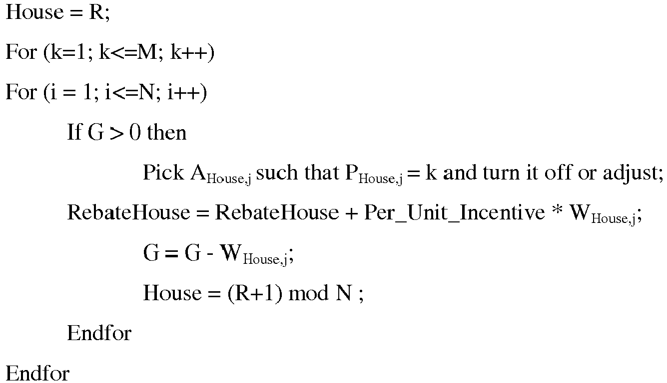
-
Algorithm 1 therefore provides a rebate for participating as well as a per-unit (wattage) incentive for saved power for each user house that participates in the demand reduction executed by the system. The rebate and/or the per-unit incentive may be applied to a bill or by way of a deposit into a bank account or a check sent in the mail. - Now, assume there are two categories of appliances such as (1) basic and (2) luxury. House i has Mi,j luxury appliances: Li,1, Li,2, ..., Li,Mi,1 and Mi,2 basic appliances: Bi,1, Bi,2, ..., Bi, Mi,2· These two categories are just examples, and could be expanded to include a spectrum of categories tied to levels of need, for instance: Critical+, Critical, Basic+, Basic, Comfort+, Comfort, Luxury+, and Luxury. For instance, the system may assign categories to appliances according to this spectrum:
- Critical: Medical devices (Heart Rate monitor, ECG etc.);
- Critical+: Critical plus Ventilation system etc.
- Basic: Lights + TV;
- Basic+: Basic plus Fans;
- Comfort: Basic plus Heater, Refrigerator, Microwave, Washing Machine, and/or Dishwasher;
- Comfort+: Comfort plus AC and Home Theater system;
- Luxury: Comfort plus Jacuzzi, etc.;
- Luxury+: Luxury plus Home Automation System etc.;
- The preference of critical or basic appliances is higher while that of luxury appliances is lower. Preference of Basic appliance j in House i is denoted by PBi,j while Preference of Luxury appliance j in House i is denoted by PLi,j. The system may assign a critical or critical+ category to certain life-saving or medical-related appliances as a threshold category to make sure they are highly prioritized and always powered at normal levels by the power grid, absent a natural disaster.
- One (1) is the lowest priority (should be turned off or adjusted first); and Mi,j is the highest priority of luxury appliances while Mi,2 is the highest priority of basic appliances.
- Choose a random number R1 between 1 and N, thus choosing a user's house randomly.


- Now, assume there are two categories of users: premier (or more-preferred) and non-premier (or less-preferred). Also assume that User Category of House i is denoted by CCi and CCi = P for Premier users and CCi = NP for Non-Premier users.
- While for purposes of Algorithm 3 (below) the two categories makes the example easier to follow, the
systems - Bronze: 5 cents/KWH
- Silver: 10 cents/KWH
- Gold: 20 cents/KWH
- Platinum: 35 cents/KWH
- Diamond: 50 cents/KWH
- Categorizing users in this way may be executed as a monetary exchange or bidding system in which users who outbid other users may receive a more-preferred status.
- Choose a random number R1 between 1 and N.


- Now, assume every house has a different willingness to pay for basic and luxury appliances and the houses are sorted such that
House 1 has the lowest willingness to pay while house N has the highest willing to pay. In addition, the per-unit incentive is also different for each house. -


-
Figure 4 is a flow chart of an exemplary method for reducing demand on a power grid through demand side management as executed by a central utility. The method may be executed by at least one processor and memory of a computing device of the disclosed system. - At
block 410, the system receives assigned priorities from a user for a plurality of smart appliances and for appliances plugged into corresponding sockets of one or more smart plugs of the user, the assigned priorities indicative of a user-preferred sequence for disconnection of, or adjustment of power to, the plurality of appliances from the power grid. Atblock 420, the system determines whether to disconnect to adjust power to at least one of the appliances of the user. Atblock 430, the system selects at least one of the appliances according to the assigned priorities to reduce demand on the power grid. Atblock 440, the system sends one or more commands, the one or more commands indicative to the one or more smart plugs to adjust or disconnect power to the selected at least one of the appliances, based on selecting at least one of the plurality of appliances. -
Figure 5 is a flow chart of another exemplary method for reducing demand on a power grid through demand side management as executed by a central utility. The method may be executed by at least one processor and memory of a computing device of the disclosed system. - At
block 510, the system receives data from sensors coupled with sockets of one or more smart appliances and smart plugs over a network, the sockets paired to a plurality of appliances of a user, the data indicative of power consumption of the respective appliances. Atblock 520, the system sends information related to the data for the respective appliances to a graphical user or network interface (GUI) of a user computing device of the user. Atblock 530, the system receives an assigned priority for the respective appliances from the GUI, the assigned priorities indicative of preference that the respective appliances not have their power levels adjusted, including and up to disconnection from being powered by the power grid. Atblock 540, sends commands to one or more smart appliances or smart plugs to disconnect or adjust power to one or more respective appliances according to the assigned priorities to reduce demand on the power grid. -
Figure 6 is a flow chart of a method for reducing demand on a power grid through demand side management of the power grid from the perspective of a smart plug located at a user site. The method may be executed by at least one processor of the smart plug. - At
block 610, one or more smart plugs gather data from sensors coupled with sockets of the one or more smart plugs, the data related to at least power usage of the appliances connected to each respective socket. Atblock 620, the one or more smart plugs send the data through a network interface of the one or more smart plugs over at least one network for transmission to a data center. Atblock 630, the one or more smart plugs execute one or more commands received from the data center to disconnect power to one or more of the appliances according to priorities assigned by a user to the respective appliances. At block 640, the assigned priorities are indicative of a user-preferred sequence for disconnection of the plurality of appliances from the power grid. - In the method of
Figure 6 , executing the commands may include identifying corresponding sockets to which the one or more appliances to be disconnected or adjusted are connected; disconnecting power to the corresponding sockets including the processor opening a relay or switch connected to the corresponding sockets of appliances to be disconnected; and varying an amount of power allowed to reach the corresponding sockets including the processor varying a controller of appliances to be adjusted. - In the method of
Figure 6 , at least one of the sensors may also provide data related to an environment in which the one or more smart plugs reside, where executing commands further includes disconnecting or adjusting the one or more appliances based on information derived from the data obtained from the environment detected by the at least one sensor. - In the method of
Figure 6 , the appliances may be assigned a higher priority are disconnected or adjusted before appliances assigned a lower priority. In the method ofFigure 6 , the appliances may further include at least one smart appliance connected directly to the power grid and that includes at least one sensor and the at least one processor, the commands executable by the at least one processor of the at least one smart appliance and the at least one smart appliance being associated with one of the assigned priorities. -
Figure 7 illustrates ageneral computer system 700, programmable to be aspecific computer system 700, which may represent any server, computer or component such as a smart plug 100 (or group thereof) of the demandside management system computer system 700 may include an ordered listing of a set ofinstructions 702 that may be executed to cause thecomputer system 700 to perform any one or more of the methods or computer-based functions disclosed herein. Thecomputer system 700 may operate as a stand-alone device or may be connected, e.g., using thenetwork - In a networked deployment, the
computer system 700 may operate in the capacity of a server or as a client-user computer in a server-client user network environment, or as a peer computer system in a peer-to-peer (or distributed) network environment. Thecomputer system 700 may also be implemented as or incorporated into various devices, such as a personal computer or a mobile computing device capable of executing a set ofinstructions 702 that specify actions to be taken by that machine, including and not limited to, accessing the Internet or Web through any form of browser. Further, each of the systems described may include any collection of sub-systems that individually or jointly execute a set, or multiple sets, of instructions to perform one or more computer functions. - The
computer system 700 may include amemory 704 on abus 720 for communicating information. Code operable to cause the computer system to perform any of the acts or operations described herein may be stored in thememory 704. Thememory 704 may be a random-access memory, read-only memory, programmable memory, hard disk drive or any other type of volatile or non-volatile memory or storage device. - The
computer system 700 may include aprocessor 708, such as a central processing unit (CPU) and/or a graphics processing unit (GPU). Theprocessor 708 may include one or more general processors, digital signal processors, application specific integrated circuits, field programmable gate arrays, digital circuits, optical circuits, analog circuits, combinations thereof, or other now known or later-developed devices for analyzing and processing data. The processor 608 may implement the set ofinstructions 702 or other software program, such as manually-programmed or computer-generated code for implementing logical functions. The logical function or any system element described may, among other functions, process and/or convert an analog data source such as an analog electrical, audio, or video signal, or a combination thereof, to a digital data source for audio-visual purposes or other digital processing purposes such as for compatibility for computer processing. - The
computer system 700 may also include a disk oroptical drive unit 715. Thedisk drive unit 715 may include a computer-readable medium 740 in which one or more sets ofinstructions 702, e.g., software, can be embedded. Further, theinstructions 702 may perform one or more of the operations as described herein. Theinstructions 702 may reside completely, or at least partially, within thememory 704 and/or within theprocessor 708 during execution by thecomputer system 700. Accordingly, the databases indata storage 207 above inFigures 2 and3 may be stored in thememory 704 and/or thedisk unit 715. - The
memory 704 and theprocessor 708 also may include computer-readable media as discussed above. A "computer-readable medium," "computer-readable storage medium," "machine readable medium," "propagated-signal medium," and/or "signal-bearing medium" may include any device that includes, stores, communicates, propagates, or transports software for use by or in connection with an instruction executable system, apparatus, or device. The machine-readable medium may selectively be, but not limited to, an electronic, magnetic, optical, electromagnetic, infrared, or semiconductor system, apparatus, device, or propagation medium. - Additionally, the
computer system 700 may include aninput device 725, such as a keyboard or mouse, configured for a user to interact with any of the components ofsystem 700. It may further include adisplay 770, such as a liquid crystal display (LCD), a cathode ray tube (CRT), or any other display suitable for conveying information. Thedisplay 770 may act as an interface for the user to see the functioning of theprocessor 708, or specifically as an interface with the software stored in thememory 704 or thedrive unit 715. - The
computer system 700 may include acommunication interface 736 that allows communications via thecommunications network network communication interface 736 network may allow communications via any number of communication standards, such as 802.11, 802.17, 802.20, WiMax, 802.15.4, cellular telephone standards, or other communication standards. Just because one of these standards is listed does not mean any one is preferred as any number of these standards may never actually be adopted in a commercial product. - Accordingly, the method and system may be realized in hardware, software, or a combination of hardware and software. The method and system may be realized in a centralized fashion in at least one computer system or in a distributed fashion where different elements are spread across several interconnected computer systems. Any kind of computer system or other apparatus adapted for carrying out the methods described herein is suited. A typical combination of hardware and software may be a general-purpose computer system with a computer program that, when being loaded and executed, controls the computer system such that it carries out the methods described herein. Such a programmed computer may be considered a special-purpose computer.
- The method and system may also be embedded in a computer program product, which includes all the features allowing the implementation of the operations described herein and which, when loaded in a computer system, is able to carry out these operations. Computer program in the present context means any expression, in any language, code or notation, of a set of instructions intended to cause a system having an information processing capability to perform a particular function, either directly or after either or both of the following: a) conversion to another language, code or notation; b) reproduction in a different material form.
- The above-disclosed subject matter is to be considered illustrative, and not restrictive, and the appended claims are intended to cover all such modifications, enhancements, and other embodiments, which fall within the true spirit and scope of the present disclosure. Thus, to the maximum extent allowed by law, the scope of the present embodiments are to be determined by the broadest permissible interpretation of the following claims and their equivalents, and shall not be restricted or limited by the foregoing detailed description. While various embodiments have been described, it will be apparent to those of ordinary skill in the art that many more embodiments and implementations are possible within the scope of the above detailed description. Accordingly, the embodiments are not to be restricted except in light of the attached claims and their equivalents.
Claims (15)
- A method comprising:receiving, using a computer having at least one processor and memory, assigned priorities from a user for a plurality of appliances, the assigned priorities indicative of a user-preferred sequence for disconnection of, or adjustment of power to, the plurality of appliances from a power grid;determining, using the at least one processor, whether to disconnect or adjust power to at least one of the appliances of the user;selecting at least one of the plurality of appliances according to the assigned priorities to reduce demand on the power grid; andbased on selecting at least one of the plurality of appliances, sending one or more commands with the computer, the one or more commands indicative to the one or more appliances to disconnect or adjust power to the selected at least one of the appliances, to thus reduce demand on the power grid through demand side management thereof.
- The method of claim 1, where the plurality of appliances comprise smart appliances configured to execute the commands to disconnect or adjust power to the selected at least one of the appliances, where each smart appliance includes at least one sensor coupled with a power connector thereof, the method further comprising:receiving data from the smart appliances over a network, the data generated by the sensors and indicative of power usage of the respective smart appliances; andsending information related to the data for the respective smart appliances to a user computing device of the user for presentation in a graphical user interface (GUI) executable on the user computing device.
- The method of claim 1, where the plurality of appliances are plugged into corresponding sockets of one or more smart plugs of the user, the one or more smart plugs configured to disconnect or adjust power to the selected at least one or the appliances, where each smart plug includes one or more sockets and at least one sensor coupled with each respective socket, the sockets paired with the respective appliances, the method further comprising:receiving data from the one or more smart plugs over a network, the data generated by the sensors and indicative of at least power usage of the respective appliances; andsending information related to the data for the respective appliances to a user computing device of the user for presentation in a graphical user interface (GUI) executable on the user computing device.
- The method of any of claims 2 to 3, further comprising:receiving, from the GUI, the assigned priorities as entered by the user for the respective appliances.
- The method of any of claim 3, where each smart plug includes one or more sockets and at least one sensor coupled with each respective socket, the sockets paired with the respective appliances, and where an appliance assigned a low priority is disconnected or adjusted before an appliance assigned a high priority, the method further comprising:receiving data from one or more sensors over a network, the data indicative of a category of the respective appliances;categorizing the at least some of the respective appliances based on the data;assigning a low priority to appliances categorized as less-important or luxury;assigning a medium to high priority to appliances categorized as basic; andassigning a high priority to appliances categorized as necessary or critical.
- The method of claim 1, further comprising:assigning a threshold priority to appliances of a specific, identified type.
- The method of claim 1, where the assigned priority for each respective appliance changes depending on one or both of: a day of a week and a time of day.
- A system for reducing demand on a power grid through demand side management thereof, comprising:at least one server including at least one processor and computer memory;a network interface coupled with the at least one server configured to communicate with user sites over at least one network;the processor configured to:receive assigned priorities from a user for a plurality of appliances, the assigned priorities indicative of a user-preferred sequence for disconnection of, or adjustment of power to, the plurality of appliances from the power grid;determine whether to disconnect or adjust power to one of the appliances of the user;select at least one of the plurality of appliances according to the assigned priorities to reduce demand on the power grid; andsend one or more commands through the network interface based on selecting at least one of the plurality of appliances, the one or more commands indicative to the one or more appliances to disconnect or adjust power to the selected at least one of the appliances.
- The system of claim 8, where the plurality of appliances comprise smart appliances configured to execute the commands to disconnect or adjust power to the selected at least one of the appliances, where each smart appliance includes at least one sensor coupled with a power connector thereof, the at least one processor further configured to:receive data from the smart appliances over the at least one network, the data generated by the sensors and indicative of at least power usage of the respective smart appliances; andsend information related to the data for the respective smart appliances to a user computing device of the user for presentation in a graphical user interface (GUI) executable on the user computing device.
- The system of claim 8, where the plurality of appliances comprise smart appliances configured to execute the commands to disconnect or adjust power to the selected at least one of the appliances, where each smart appliance includes at least one sensor coupled with a power connector thereof, where at least one sensor of one of the smart appliances is further configured to provide data related to an environment of a corresponding smart appliance, the at least one processor further configured to:send a command to the selected at least one of the smart appliances to disconnect or adjust the at least one of the appliances based at least in part on information derived from the data obtained from the environment detected by the at least one sensor.
- The system of claim 8, where the plurality of appliances are plugged into corresponding sockets of one or more smart plugs of the user, the one or more smart plugs configured to disconnect or adjust power to the selected at least one or the appliances, where each smart plug includes one or more sockets and at least one sensor coupled with each respective socket, the sockets paired with the respective appliances, the at least one processor further configured to:receive data from the one or more smart plugs over the at least one network, the data generated by the sensors and indicative of at least power usage of the respective appliances; andsend information related to the data for the respective appliances to a user computing device of the user for presentation in a graphical user interface (GUI) executable on the user computing device.
- The system of claims 9 or 11, where the at least one processor is further configured to receive, from the GUI, the assigned priorities as entered by the user for the respective appliances.
- The system of any of claim 11, where each smart plug includes one or more sockets and at least one sensor coupled with each respective socket, the sockets paired with the respective appliances, and where an appliance assigned a low priority is disconnected or adjusted before an appliance assigned a high priority, the at least one processor further configured to:receive data from one or more sensors over a network, the data indicative of a category of the respective appliances;categorize the at least some of the respective appliances based on the data;assign a low priority to appliances categorized as less-important or luxury;assign a medium to high priority to appliances categorized as basic; andassign a high priority to appliances categorized as necessary or critical.
- The system of claim 8, the at least one processor further configured to assign a threshold priority to appliances of a specific, identified type.
- The system of claim 8, where the assigned priority for each respective appliance changes depending on one or both of: a day of a week and a time of day.
Applications Claiming Priority (1)
| Application Number | Priority Date | Filing Date | Title |
|---|---|---|---|
| IN932CH2012 | 2012-03-14 |
Publications (2)
| Publication Number | Publication Date |
|---|---|
| EP2639920A2 true EP2639920A2 (en) | 2013-09-18 |
| EP2639920A3 EP2639920A3 (en) | 2016-12-21 |
Family
ID=47901803
Family Applications (1)
| Application Number | Title | Priority Date | Filing Date |
|---|---|---|---|
| EP13159305.5A Withdrawn EP2639920A3 (en) | 2012-03-14 | 2013-03-14 | User-centric demand side management for utilities |
Country Status (3)
| Country | Link |
|---|---|
| US (2) | US9329650B2 (en) |
| EP (1) | EP2639920A3 (en) |
| AU (1) | AU2013201515B2 (en) |
Cited By (3)
| Publication number | Priority date | Publication date | Assignee | Title |
|---|---|---|---|---|
| WO2016172037A3 (en) * | 2015-04-24 | 2017-03-30 | Emerson Electric Co. | Control unit for undersink appliances faucet having an undersink faucet base and an above sink faucet head |
| WO2019033146A1 (en) * | 2017-08-17 | 2019-02-21 | Zen Ecosystems IP Pty Ltd | Method, system and apparatus for optimising energy consumption |
| EP3582365A1 (en) | 2018-06-15 | 2019-12-18 | Universita Degli Studi Di Cagliari | Method and architecture for managing the energy demand of the multi-agent type for reducing the peaks of electrical consumption of a plurality of electrical appliances |
Families Citing this family (43)
| Publication number | Priority date | Publication date | Assignee | Title |
|---|---|---|---|---|
| US9172245B1 (en) * | 2010-12-06 | 2015-10-27 | Sandia Corporation | Intelligent electrical outlet for collective load control |
| US9329650B2 (en) | 2012-03-14 | 2016-05-03 | Accenture Global Services Limited | Customer-centric demand side management for utilities |
| US10158213B2 (en) | 2013-02-22 | 2018-12-18 | Milwaukee Electric Tool Corporation | Worksite power distribution box |
| CN104285216B (en) * | 2013-03-08 | 2017-08-08 | 松下电器(美国)知识产权公司 | Information sharing method |
| US9599973B2 (en) * | 2013-03-14 | 2017-03-21 | International Business Machines Corporation | Interactive energy device for environmental stewardship |
| EP2974435A4 (en) * | 2013-03-14 | 2016-11-02 | Kool Koncepts Ltd | Energy management system |
| KR102085114B1 (en) * | 2013-07-17 | 2020-03-05 | 삼성전자주식회사 | Method and apparatus for communication using smart module in home network system |
| US9883257B2 (en) * | 2013-08-14 | 2018-01-30 | Atmel Corporation | Smart grid appliance control |
| GB201315141D0 (en) * | 2013-08-23 | 2013-10-09 | Logicor R & D Ltd | Improvements to electric heating systems and method of use thereof |
| KR101590698B1 (en) * | 2014-03-31 | 2016-02-01 | 엘지전자 주식회사 | Apparatus for detecting a power supply |
| CN104021429A (en) * | 2014-06-12 | 2014-09-03 | 国家电网公司 | Management method of intelligent power grid demand side |
| CN104678851B (en) | 2015-01-29 | 2018-03-16 | 小米科技有限责任公司 | Smart jack method of controlling switch and device |
| JP5975135B1 (en) | 2015-03-31 | 2016-08-23 | ダイキン工業株式会社 | Control system |
| CN104965452B (en) * | 2015-06-23 | 2018-04-27 | 小米科技有限责任公司 | Intelligent socket on off state display methods and device, intelligent terminal and server |
| GB2540364B (en) | 2015-07-14 | 2020-07-22 | Samsung Electronics Co Ltd | Power load management apparatus and method |
| US10181959B2 (en) * | 2015-07-27 | 2019-01-15 | International Business Machines Corporation | Methods and systems for mindful home automation |
| JP6420912B2 (en) * | 2015-08-12 | 2018-11-07 | 京セラ株式会社 | Management server, management method and management system |
| US11424601B2 (en) * | 2015-11-02 | 2022-08-23 | Milwaukee Electric Tool Corporation | Externally configurable worksite power distribution box |
| CN106896731A (en) * | 2015-12-18 | 2017-06-27 | 英业达科技有限公司 | The devices and methods therefor of household electrical appliances behaviour in service is shown according to user's position control |
| CN105976046B (en) * | 2016-04-27 | 2022-02-25 | 中国电力科学研究院 | Low-carbon power grid planning method considering demand side management |
| US10013382B2 (en) * | 2016-04-27 | 2018-07-03 | Quanta Computer Inc. | Smart plug node management |
| US10623509B2 (en) * | 2016-07-28 | 2020-04-14 | Accenture Global Solutions Limited | Intelligent maintenance and repair of user properties |
| CA3033258A1 (en) * | 2016-08-08 | 2018-02-15 | Orison, Inc. | Plug and play with smart energy storage units |
| AU2017350912A1 (en) | 2016-10-28 | 2019-05-30 | Insight Energy Ventures, Llc | Method of intelligent demand response |
| CA3042027A1 (en) | 2016-10-28 | 2018-05-03 | Insight Energy Ventures, Llc | Method of disaggregating an energy usage signal of a usage area |
| US10587118B2 (en) * | 2016-11-15 | 2020-03-10 | Solaredge Technologies Ltd. | Smart outlet |
| US10735406B1 (en) | 2016-12-21 | 2020-08-04 | Wells Fargo Bank, N.A. | Customer centric grid for customer services |
| GB2559389B (en) * | 2017-02-03 | 2022-09-14 | Green Running Ltd | A smart plug with current and voltage detection |
| US11239660B2 (en) * | 2017-05-10 | 2022-02-01 | Korea Electronics Technology Institute | Demand response system and method for controlling devices to participate in demand response automatically |
| US10614507B2 (en) * | 2017-07-03 | 2020-04-07 | Mastercard International Incorporated | Systems and methods for using smart appliances to provide contextual user experiences |
| CA3111027A1 (en) * | 2017-09-15 | 2019-03-21 | Cheuk Kwan LUI | Utility power distribution branch management system |
| US11287285B2 (en) * | 2017-12-18 | 2022-03-29 | Landis+Gyr Innovations, Inc. | Methods and systems for distributed verification and control of a resource distribution network |
| US10608432B2 (en) | 2018-03-30 | 2020-03-31 | Midea Group Co., Ltd. | Appliance power management system |
| US10852759B2 (en) * | 2018-12-19 | 2020-12-01 | Intel Corporation | Flexibility-based ranking of utility customers for determining constraints on power demand |
| US11106263B2 (en) | 2019-01-31 | 2021-08-31 | Sapient Industries, Inc. | Region-based electrical intelligence system |
| CN111596551A (en) * | 2019-02-20 | 2020-08-28 | 青岛海尔洗衣机有限公司 | Control method of intelligent socket of home system, intelligent socket and home system |
| US11140156B2 (en) * | 2019-07-16 | 2021-10-05 | Mastercard International Incorporated | Systems and methods for use in binding internet of things devices with identities associated with users |
| US11449821B2 (en) | 2019-07-16 | 2022-09-20 | Mastercard International Incorporated | Systems and methods for use in facilitating verified deliveries |
| US11537703B2 (en) * | 2019-10-11 | 2022-12-27 | Moon River Investments, Llc | GFI tripped circuit detection and wireless notification systems and methods |
| US11656097B2 (en) | 2019-10-29 | 2023-05-23 | Martha Patricia Vega | Methods, systems, apparatuses and devices for optimizing utility consumption associated with at least one premises |
| US11533457B2 (en) | 2019-11-27 | 2022-12-20 | Aob Products Company | Smart home and security system |
| CN111596934B (en) * | 2020-04-17 | 2022-08-05 | 安科讯(福建)科技有限公司 | FPGA (field programmable Gate array) remote upgrading method and terminal for RRU (remote radio Unit) equipment of 5G (fourth Generation) distributed base station |
| US11681345B2 (en) * | 2020-07-10 | 2023-06-20 | Sapient Industries, Inc. | Powered device electrical data modeling and intelligence |
Citations (3)
| Publication number | Priority date | Publication date | Assignee | Title |
|---|---|---|---|---|
| US20050207081A1 (en) * | 2001-07-10 | 2005-09-22 | Jeffrey Ying | System for remotely controlling energy distribution at local sites |
| EP1955416A1 (en) * | 2005-11-30 | 2008-08-13 | Seong-Kyu Lim | Power-controllable outlet receptacle |
| US20090062970A1 (en) * | 2007-08-28 | 2009-03-05 | America Connect, Inc. | System and method for active power load management |
Family Cites Families (37)
| Publication number | Priority date | Publication date | Assignee | Title |
|---|---|---|---|---|
| US260207A (en) | 1882-06-27 | Draft-equalizer | ||
| CH667546A5 (en) * | 1985-07-26 | 1988-10-14 | Autelca Ag | COIN CHECKING DEVICE. |
| US5793125A (en) * | 1991-02-25 | 1998-08-11 | Tarng; Min Ming | Smart integrated socket automation system |
| US5572438A (en) | 1995-01-05 | 1996-11-05 | Teco Energy Management Services | Engery management and building automation system |
| US5575483A (en) * | 1995-09-26 | 1996-11-19 | Dineen; Robert T. | Golf toss game |
| US6583521B1 (en) | 2000-03-21 | 2003-06-24 | Martin Lagod | Energy management system which includes on-site energy supply |
| US6633823B2 (en) | 2000-07-13 | 2003-10-14 | Nxegen, Inc. | System and method for monitoring and controlling energy usage |
| US20030171851A1 (en) | 2002-03-08 | 2003-09-11 | Peter J. Brickfield | Automatic energy management and energy consumption reduction, especially in commercial and multi-building systems |
| CN1656661A (en) | 2002-03-28 | 2005-08-17 | 罗伯绍控制器公司 | Energy management system and method |
| WO2003085798A2 (en) | 2002-04-01 | 2003-10-16 | Battelle Memorial Institute | Energy management system |
| EP1367685A1 (en) * | 2002-05-31 | 2003-12-03 | Whirlpool Corporation | Electronic system for power consumption management of appliances |
| US7689323B2 (en) | 2003-05-13 | 2010-03-30 | Siemens Aktiengesellschaft | Automatic generation control of a power distribution system |
| JP2007510394A (en) | 2003-10-24 | 2007-04-19 | スクエア・ディー・カンパニー | Intelligent power management control system |
| US20050240427A1 (en) | 2004-04-26 | 2005-10-27 | Crichlow Henry B | Energy management method and process using analytic metrics. |
| US8429630B2 (en) | 2005-09-15 | 2013-04-23 | Ca, Inc. | Globally distributed utility computing cloud |
| CA2630169A1 (en) | 2005-11-25 | 2007-05-31 | Computerized Electricity Systems Ltd. | Flexible electric load management system and method therefor |
| US7657763B2 (en) * | 2005-12-29 | 2010-02-02 | Panasonic Electric Works Co., Ltd. | Systems and methods for selectively controlling electrical outlets using power profiling |
| EP2005202A4 (en) | 2006-04-12 | 2011-03-16 | Edsa Micro Corp | Systems and methods for performing automatic real-time harmonics analyses for use in real-time power analytics of an electrical power distribution system |
| NL2000444C2 (en) | 2007-01-18 | 2008-07-22 | Sudotec B V | Energy management system. |
| US20080177678A1 (en) | 2007-01-24 | 2008-07-24 | Paul Di Martini | Method of communicating between a utility and its customer locations |
| NZ580322A (en) * | 2007-03-14 | 2012-11-30 | Zonit Structured Solutions Llc | Controlling electrical appliances using TCP/IP controlled outlets with power interruption or reduction functions |
| US7940673B2 (en) * | 2007-06-06 | 2011-05-10 | Veedims, Llc | System for integrating a plurality of modules using a power/data backbone network |
| US8176095B2 (en) | 2007-06-11 | 2012-05-08 | Lucid Design Group, Llc | Collecting, sharing, comparing, and displaying resource usage data |
| US7693670B2 (en) | 2007-08-14 | 2010-04-06 | General Electric Company | Cognitive electric power meter |
| US8000913B2 (en) | 2008-01-21 | 2011-08-16 | Current Communications Services, Llc | System and method for providing power distribution system information |
| US8239073B2 (en) | 2008-04-17 | 2012-08-07 | Asoka Usa Corporation | Systems and methods for controlling energy consumption |
| US20090326725A1 (en) | 2008-05-19 | 2009-12-31 | Michael James Carlson | Managing Electric Power Consumption |
| US20100332373A1 (en) | 2009-02-26 | 2010-12-30 | Jason Crabtree | System and method for participation in energy-related markets |
| US8315745B2 (en) * | 2009-04-24 | 2012-11-20 | Hunter Defense Technologies, Inc. | Mobile micro-grid power system controller and method |
| WO2010141859A1 (en) * | 2009-06-05 | 2010-12-09 | Leviton Manufacturing Co., Inc. | Smart grid over power line communication network |
| EP2290328B1 (en) | 2009-08-24 | 2015-03-04 | Accenture Global Services Limited | Utility management system |
| US8543247B2 (en) | 2010-01-08 | 2013-09-24 | International Business Machines Corporation | Power profile management method and system |
| EP2348596B1 (en) | 2010-01-25 | 2021-09-08 | Accenture Global Services Limited | Analytics for consumer power consumption |
| US8604914B2 (en) * | 2010-11-17 | 2013-12-10 | International Business Machines Corporation | Smart power sockets, boards, and plugs |
| WO2012077058A2 (en) * | 2010-12-06 | 2012-06-14 | Smart Grid Billing, Inc | Apparatus and method for controlling consumer electric power consumption |
| US20110184876A1 (en) * | 2010-12-30 | 2011-07-28 | Ziprealty, Inc. | Virtual bidding platform for lead allocation in real estate applications |
| US9329650B2 (en) | 2012-03-14 | 2016-05-03 | Accenture Global Services Limited | Customer-centric demand side management for utilities |
-
2013
- 2013-02-20 US US13/771,827 patent/US9329650B2/en active Active
- 2013-03-14 AU AU2013201515A patent/AU2013201515B2/en active Active
- 2013-03-14 EP EP13159305.5A patent/EP2639920A3/en not_active Withdrawn
-
2016
- 2016-04-06 US US15/092,352 patent/US9876357B2/en active Active
Patent Citations (3)
| Publication number | Priority date | Publication date | Assignee | Title |
|---|---|---|---|---|
| US20050207081A1 (en) * | 2001-07-10 | 2005-09-22 | Jeffrey Ying | System for remotely controlling energy distribution at local sites |
| EP1955416A1 (en) * | 2005-11-30 | 2008-08-13 | Seong-Kyu Lim | Power-controllable outlet receptacle |
| US20090062970A1 (en) * | 2007-08-28 | 2009-03-05 | America Connect, Inc. | System and method for active power load management |
Cited By (6)
| Publication number | Priority date | Publication date | Assignee | Title |
|---|---|---|---|---|
| WO2016172037A3 (en) * | 2015-04-24 | 2017-03-30 | Emerson Electric Co. | Control unit for undersink appliances faucet having an undersink faucet base and an above sink faucet head |
| US10407884B2 (en) | 2015-04-24 | 2019-09-10 | Emerson Electric Co. | Control unit for undersink appliances faucet having an undersink faucet base and an above sink faucet head |
| US10920404B2 (en) | 2015-04-24 | 2021-02-16 | Emerson Electric Co. | Control unit for undersink appliances |
| US11542693B2 (en) | 2015-04-24 | 2023-01-03 | Emerson Electric Co. | Control unit for undersink appliances |
| WO2019033146A1 (en) * | 2017-08-17 | 2019-02-21 | Zen Ecosystems IP Pty Ltd | Method, system and apparatus for optimising energy consumption |
| EP3582365A1 (en) | 2018-06-15 | 2019-12-18 | Universita Degli Studi Di Cagliari | Method and architecture for managing the energy demand of the multi-agent type for reducing the peaks of electrical consumption of a plurality of electrical appliances |
Also Published As
| Publication number | Publication date |
|---|---|
| US9876357B2 (en) | 2018-01-23 |
| US20130245849A1 (en) | 2013-09-19 |
| US9329650B2 (en) | 2016-05-03 |
| US20160218509A1 (en) | 2016-07-28 |
| AU2013201515B2 (en) | 2015-02-19 |
| EP2639920A3 (en) | 2016-12-21 |
| AU2013201515A1 (en) | 2013-10-03 |
Similar Documents
| Publication | Publication Date | Title |
|---|---|---|
| US9876357B2 (en) | Customer-centric demand side management for utilities | |
| US9798298B2 (en) | Community energy management system | |
| US10998764B2 (en) | System, method, and apparatus for electric power grid and network management of grid elements | |
| US11782470B2 (en) | Method and apparatus for actively managing electric power supply for an electric power grid | |
| Yaqub et al. | Smart energy‐consumption management system considering consumers' spending goals (SEMS‐CCSG) | |
| EP2663955B1 (en) | A method and system for effective management of energy consumption by household appliances | |
| CN109461094B (en) | System, apparatus and method for managing demand response programs and events | |
| US9864391B2 (en) | Tablet based distributed intelligent load management | |
| US8335596B2 (en) | Remote energy management using persistent smart grid network context | |
| RU2521611C2 (en) | System and method for reducing electric power consumption | |
| CA2754432C (en) | Distributed meter data management | |
| Moura et al. | The role of Smart Grids to foster energy efficiency | |
| US8812165B1 (en) | Electric grid optimization | |
| US8996184B2 (en) | Apparatus and method for energy management | |
| US20100023376A1 (en) | Iterative real-time auction for resource management with user rules | |
| EP2865064A1 (en) | Method and apparatus for actively managing electric power over an electric power grid | |
| US10268171B2 (en) | Demand response control result presentation apparatus | |
| US20210126459A1 (en) | Third party energy management | |
| TWI700874B (en) | An electricity supply control system and a method thereof | |
| Narimani et al. | Autonomous demand response in heterogeneous smart grid topologies | |
| Raasch et al. | Decentralized Local Pricing–Improving Network Usage in a Smart-Grid Environment under Limited Information |
Legal Events
| Date | Code | Title | Description |
|---|---|---|---|
| PUAI | Public reference made under article 153(3) epc to a published international application that has entered the european phase |
Free format text: ORIGINAL CODE: 0009012 |
|
| AK | Designated contracting states |
Kind code of ref document: A2 Designated state(s): AL AT BE BG CH CY CZ DE DK EE ES FI FR GB GR HR HU IE IS IT LI LT LU LV MC MK MT NL NO PL PT RO RS SE SI SK SM TR |
|
| AX | Request for extension of the european patent |
Extension state: BA ME |
|
| PUAL | Search report despatched |
Free format text: ORIGINAL CODE: 0009013 |
|
| AK | Designated contracting states |
Kind code of ref document: A3 Designated state(s): AL AT BE BG CH CY CZ DE DK EE ES FI FR GB GR HR HU IE IS IT LI LT LU LV MC MK MT NL NO PL PT RO RS SE SI SK SM TR |
|
| AX | Request for extension of the european patent |
Extension state: BA ME |
|
| RIC1 | Information provided on ipc code assigned before grant |
Ipc: H02J 3/14 20060101AFI20161116BHEP |
|
| 17P | Request for examination filed |
Effective date: 20170621 |
|
| RBV | Designated contracting states (corrected) |
Designated state(s): AL AT BE BG CH CY CZ DE DK EE ES FI FR GB GR HR HU IE IS IT LI LT LU LV MC MK MT NL NO PL PT RO RS SE SI SK SM TR |
|
| 17Q | First examination report despatched |
Effective date: 20180508 |
|
| STAA | Information on the status of an ep patent application or granted ep patent |
Free format text: STATUS: THE APPLICATION IS DEEMED TO BE WITHDRAWN |
|
| 18D | Application deemed to be withdrawn |
Effective date: 20200603 |