EP2639824A2 - Robot system and method of manufacturing workpiece - Google Patents
Robot system and method of manufacturing workpiece Download PDFInfo
- Publication number
- EP2639824A2 EP2639824A2 EP12170128.8A EP12170128A EP2639824A2 EP 2639824 A2 EP2639824 A2 EP 2639824A2 EP 12170128 A EP12170128 A EP 12170128A EP 2639824 A2 EP2639824 A2 EP 2639824A2
- Authority
- EP
- European Patent Office
- Prior art keywords
- robot
- workpiece
- predetermined
- board
- robot system
- Prior art date
- Legal status (The legal status is an assumption and is not a legal conclusion. Google has not performed a legal analysis and makes no representation as to the accuracy of the status listed.)
- Withdrawn
Links
Images


Classifications
-
- H—ELECTRICITY
- H05—ELECTRIC TECHNIQUES NOT OTHERWISE PROVIDED FOR
- H05K—PRINTED CIRCUITS; CASINGS OR CONSTRUCTIONAL DETAILS OF ELECTRIC APPARATUS; MANUFACTURE OF ASSEMBLAGES OF ELECTRICAL COMPONENTS
- H05K3/00—Apparatus or processes for manufacturing printed circuits
- H05K3/0091—Apparatus for coating printed circuits using liquid non-metallic coating compositions
-
- B—PERFORMING OPERATIONS; TRANSPORTING
- B05—SPRAYING OR ATOMISING IN GENERAL; APPLYING FLUENT MATERIALS TO SURFACES, IN GENERAL
- B05B—SPRAYING APPARATUS; ATOMISING APPARATUS; NOZZLES
- B05B13/00—Machines or plants for applying liquids or other fluent materials to surfaces of objects or other work by spraying, not covered by groups B05B1/00 - B05B11/00
- B05B13/02—Means for supporting work; Arrangement or mounting of spray heads; Adaptation or arrangement of means for feeding work
- B05B13/0221—Means for supporting work; Arrangement or mounting of spray heads; Adaptation or arrangement of means for feeding work characterised by the means for moving or conveying the objects or other work, e.g. conveyor belts
-
- B—PERFORMING OPERATIONS; TRANSPORTING
- B05—SPRAYING OR ATOMISING IN GENERAL; APPLYING FLUENT MATERIALS TO SURFACES, IN GENERAL
- B05C—APPARATUS FOR APPLYING FLUENT MATERIALS TO SURFACES, IN GENERAL
- B05C5/00—Apparatus in which liquid or other fluent material is projected, poured or allowed to flow on to the surface of the work
- B05C5/02—Apparatus in which liquid or other fluent material is projected, poured or allowed to flow on to the surface of the work the liquid or other fluent material being discharged through an outlet orifice by pressure, e.g. from an outlet device in contact or almost in contact, with the work
- B05C5/0208—Apparatus in which liquid or other fluent material is projected, poured or allowed to flow on to the surface of the work the liquid or other fluent material being discharged through an outlet orifice by pressure, e.g. from an outlet device in contact or almost in contact, with the work for applying liquid or other fluent material to separate articles
- B05C5/0212—Apparatus in which liquid or other fluent material is projected, poured or allowed to flow on to the surface of the work the liquid or other fluent material being discharged through an outlet orifice by pressure, e.g. from an outlet device in contact or almost in contact, with the work for applying liquid or other fluent material to separate articles only at particular parts of the articles
-
- H—ELECTRICITY
- H05—ELECTRIC TECHNIQUES NOT OTHERWISE PROVIDED FOR
- H05K—PRINTED CIRCUITS; CASINGS OR CONSTRUCTIONAL DETAILS OF ELECTRIC APPARATUS; MANUFACTURE OF ASSEMBLAGES OF ELECTRICAL COMPONENTS
- H05K13/00—Apparatus or processes specially adapted for manufacturing or adjusting assemblages of electric components
- H05K13/04—Mounting of components, e.g. of leadless components
- H05K13/046—Surface mounting
- H05K13/0469—Surface mounting by applying a glue or viscous material
-
- H—ELECTRICITY
- H10—SEMICONDUCTOR DEVICES; ELECTRIC SOLID-STATE DEVICES NOT OTHERWISE PROVIDED FOR
- H10P—GENERIC PROCESSES OR APPARATUS FOR THE MANUFACTURE OR TREATMENT OF DEVICES COVERED BY CLASS H10
- H10P72/00—Handling or holding of wafers, substrates or devices during manufacture or treatment thereof
- H10P72/04—Apparatus for manufacture or treatment
- H10P72/0448—Apparatus for applying a liquid, a resin, an ink or the like
-
- H—ELECTRICITY
- H10—SEMICONDUCTOR DEVICES; ELECTRIC SOLID-STATE DEVICES NOT OTHERWISE PROVIDED FOR
- H10P—GENERIC PROCESSES OR APPARATUS FOR THE MANUFACTURE OR TREATMENT OF DEVICES COVERED BY CLASS H10
- H10P72/00—Handling or holding of wafers, substrates or devices during manufacture or treatment thereof
- H10P72/30—Handling or holding of wafers, substrates or devices during manufacture or treatment thereof for conveying, e.g. between different workstations
- H10P72/33—Handling or holding of wafers, substrates or devices during manufacture or treatment thereof for conveying, e.g. between different workstations into and out of processing chamber
- H10P72/3302—Mechanical parts of transfer devices
-
- B—PERFORMING OPERATIONS; TRANSPORTING
- B05—SPRAYING OR ATOMISING IN GENERAL; APPLYING FLUENT MATERIALS TO SURFACES, IN GENERAL
- B05B—SPRAYING APPARATUS; ATOMISING APPARATUS; NOZZLES
- B05B13/00—Machines or plants for applying liquids or other fluent materials to surfaces of objects or other work by spraying, not covered by groups B05B1/00 - B05B11/00
- B05B13/02—Means for supporting work; Arrangement or mounting of spray heads; Adaptation or arrangement of means for feeding work
- B05B13/04—Means for supporting work; Arrangement or mounting of spray heads; Adaptation or arrangement of means for feeding work the spray heads being moved during spraying operation
- B05B13/0431—Means for supporting work; Arrangement or mounting of spray heads; Adaptation or arrangement of means for feeding work the spray heads being moved during spraying operation with spray heads moved by robots or articulated arms, e.g. for applying liquid or other fluent material to three-dimensional [3D] surfaces
-
- B—PERFORMING OPERATIONS; TRANSPORTING
- B05—SPRAYING OR ATOMISING IN GENERAL; APPLYING FLUENT MATERIALS TO SURFACES, IN GENERAL
- B05C—APPARATUS FOR APPLYING FLUENT MATERIALS TO SURFACES, IN GENERAL
- B05C5/00—Apparatus in which liquid or other fluent material is projected, poured or allowed to flow on to the surface of the work
- B05C5/02—Apparatus in which liquid or other fluent material is projected, poured or allowed to flow on to the surface of the work the liquid or other fluent material being discharged through an outlet orifice by pressure, e.g. from an outlet device in contact or almost in contact, with the work
- B05C5/0208—Apparatus in which liquid or other fluent material is projected, poured or allowed to flow on to the surface of the work the liquid or other fluent material being discharged through an outlet orifice by pressure, e.g. from an outlet device in contact or almost in contact, with the work for applying liquid or other fluent material to separate articles
- B05C5/0212—Apparatus in which liquid or other fluent material is projected, poured or allowed to flow on to the surface of the work the liquid or other fluent material being discharged through an outlet orifice by pressure, e.g. from an outlet device in contact or almost in contact, with the work for applying liquid or other fluent material to separate articles only at particular parts of the articles
- B05C5/0216—Apparatus in which liquid or other fluent material is projected, poured or allowed to flow on to the surface of the work the liquid or other fluent material being discharged through an outlet orifice by pressure, e.g. from an outlet device in contact or almost in contact, with the work for applying liquid or other fluent material to separate articles only at particular parts of the articles by relative movement of article and outlet according to a predetermined path
- B05C5/022—Apparatus in which liquid or other fluent material is projected, poured or allowed to flow on to the surface of the work the liquid or other fluent material being discharged through an outlet orifice by pressure, e.g. from an outlet device in contact or almost in contact, with the work for applying liquid or other fluent material to separate articles only at particular parts of the articles by relative movement of article and outlet according to a predetermined path the outlet being fixed during operation
-
- H—ELECTRICITY
- H05—ELECTRIC TECHNIQUES NOT OTHERWISE PROVIDED FOR
- H05K—PRINTED CIRCUITS; CASINGS OR CONSTRUCTIONAL DETAILS OF ELECTRIC APPARATUS; MANUFACTURE OF ASSEMBLAGES OF ELECTRICAL COMPONENTS
- H05K2201/00—Indexing scheme relating to printed circuits covered by H05K1/00
- H05K2201/01—Dielectrics
- H05K2201/0137—Materials
- H05K2201/0162—Silicon containing polymer, e.g. silicone
-
- H—ELECTRICITY
- H05—ELECTRIC TECHNIQUES NOT OTHERWISE PROVIDED FOR
- H05K—PRINTED CIRCUITS; CASINGS OR CONSTRUCTIONAL DETAILS OF ELECTRIC APPARATUS; MANUFACTURE OF ASSEMBLAGES OF ELECTRICAL COMPONENTS
- H05K2203/00—Indexing scheme relating to apparatus or processes for manufacturing printed circuits covered by H05K3/00
- H05K2203/01—Tools for processing; Objects used during processing
- H05K2203/0104—Tools for processing; Objects used during processing for patterning or coating
- H05K2203/0126—Dispenser, e.g. for solder paste, for supplying conductive paste for screen printing or for filling holes
-
- Y—GENERAL TAGGING OF NEW TECHNOLOGICAL DEVELOPMENTS; GENERAL TAGGING OF CROSS-SECTIONAL TECHNOLOGIES SPANNING OVER SEVERAL SECTIONS OF THE IPC; TECHNICAL SUBJECTS COVERED BY FORMER USPC CROSS-REFERENCE ART COLLECTIONS [XRACs] AND DIGESTS
- Y10—TECHNICAL SUBJECTS COVERED BY FORMER USPC
- Y10T—TECHNICAL SUBJECTS COVERED BY FORMER US CLASSIFICATION
- Y10T29/00—Metal working
- Y10T29/49—Method of mechanical manufacture
- Y10T29/49002—Electrical device making
- Y10T29/49117—Conductor or circuit manufacturing
- Y10T29/49124—On flat or curved insulated base, e.g., printed circuit, etc.
-
- Y—GENERAL TAGGING OF NEW TECHNOLOGICAL DEVELOPMENTS; GENERAL TAGGING OF CROSS-SECTIONAL TECHNOLOGIES SPANNING OVER SEVERAL SECTIONS OF THE IPC; TECHNICAL SUBJECTS COVERED BY FORMER USPC CROSS-REFERENCE ART COLLECTIONS [XRACs] AND DIGESTS
- Y10—TECHNICAL SUBJECTS COVERED BY FORMER USPC
- Y10T—TECHNICAL SUBJECTS COVERED BY FORMER US CLASSIFICATION
- Y10T29/00—Metal working
- Y10T29/53—Means to assemble or disassemble
- Y10T29/5313—Means to assemble electrical device
Definitions
- the embodiment discussed herein is directed to a robot system and a method of manufacturing a workpiece.
- the resin sealing apparatus includes a robot and a plurality of units.
- One of the units includes a liquid discharge apparatus.
- the units are connected by a support rail that is a conveying path for conveying the workpiece.
- the liquid discharge apparatus includes a mobile dispenser that discharges liquid resin to the workpiece.
- the dispenser discharges liquid resin to a predetermined region of the workpiece while moving over the workpiece conveyed up to a predetermined position of the support rail in three-dimensional directions.
- the conventional robot systems have further room for improvement from the viewpoint of narrowing of a working space.
- the resin sealing apparatus requires at least an arranged space of the support rail and a movable space of the dispenser.
- An aspect of an embodiment has been achieved in view of the above problem, and an object of the embodiment is to provide a robot system and a method of manufacturing a workpiece that can be used for narrowing a working space.
- a robot system includes a supply unit and a robot.
- the supply unit is fixedly provided at a predetermined position to supply a feed material that is used for processing a workpiece.
- the robot transfers the unprocessed workpiece handed from an operator at a predetermined transfer position to the vicinity of the supply unit to process the workpiece by using the feed material supplied from the supply unit and then transfers the processed workpiece to the transfer position.
- a working space can be narrowed.
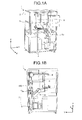
- FIGs. 1A and 1B are pattern diagrams illustrating the entire configuration of a robot system according to an embodiment
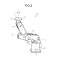
- FIG. 2 is a pattern diagram illustrating the configuration of a robot according to the embodiment
- FIG. 3A is a pattern diagram illustrating the configuration of a robot hand according to the embodiment.
- FIG. 3B is a pattern diagram when the robot hand is attached to the robot
- FIGs. 4A, 4B, and 4C are schematic pattern diagrams illustrating operations of the robot system according to the embodiment
- FIGs. 5A, 5B, and 5C are pattern diagrams illustrating a movement of a board relative to a dispenser
- FIG. 6 is a pattern diagram illustrating an example of a vibration isolation process
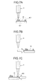
- FIGs. 7A, 7B, and 7C are pattern diagrams illustrating a dripping avoidance operation that is performed by the robot.
- silicon resin that is a liquid material is a "feed material” and a board for an electronics device is a "workpiece”.
- a robot system that attaches silicon resin to a predetermined region of the board and performs a vibration isolation process on electronic components attached to the board will be explained as an example.
- FIGs. 1A and 1B are pattern diagrams illustrating the entire configuration of a robot system 1 according to the embodiment.
- a three-dimensional rectangular coordinate system that includes Z-axis of which the positive direction is a vertically upward direction is illustrated in FIGs. 1A and 1B .
- the rectangular coordinate system can be illustrated in other drawings that are used for the following explanations.
- the positive direction of X-axis indicates the front of the robot system 1.
- the robot system 1 includes a partition wall 2 that forms a rectangular solzd-shaped working space. Moreover, a shutter part 3 and a touch panel 5 are provided in the partition wall 2 that corresponds to the front of the working space.
- the shutter part 3 is an opening part that has an openable and closable shutter.
- the touch panel 5 is an input device that receives an input instruction of an operator.
- a control device 4 and a robot 10 are provided inside the partition wall 2 and are connected to communicate with each other.
- the control device 4 is a control unit that controls operations of the robot 10.
- the control device 4 includes various control units, an arithmetic processing unit, a storage device, and the like.
- the control device 4 consists of two cases as an example. However, the number of cases is not limited to this.
- the control device 4 controls the drive of a servo motor 6 to be described below.
- control device 4 is provided at a position corresponding to the breast of the robot 10. As a result, the control device 4 can conduct to the narrowing of a working space.
- the robot 10 is a manipulator that operates in accordance with an operation instruction provided from the control device 4.
- the robot 10 includes a robot hand 15 that acts as an end effector. The details of the configuration of the robot 10 are explained below with reference to FIGs. 2 , 3A, and 3B .
- the robot system 1 further includes the servo motor 6, a cylinder part 7, a stand 8, and a dispenser 9 inside the partition wall 2.
- the cylinder part 7 includes a pressurizing unit 7a.
- a silicon cartridge 500 is provided over the pressurizing unit 7a.
- the servo motor 6 drives the cylinder part 7 in up and down directions (in other words, Z-axis direction) on the basis of the driving instruction of the control device 4.
- the cylinder part 7 pressurizes the silicon cartridge 500 from the lower side via the pressurizing unit 7a in accordance with the drive.
- the stand 8 is an erected stand that hangs the dispenser 9 that is a "supply unit” that supplies silicon resin. Moreover, a tube (not illustrated) is provided inside the stand 8. The tube sends silicon resin in the silicon cartridge 500 pressurized from the lower side as described above to the dispenser 9 by using the pressurizing force.
- the dispenser 9 is hung from the stand 8 and fixes a distal nozzle (not illustrated) at a predetermined position toward the lower side. Then, the silicon resin sent via the tube is discharged on the basis of the discharge instruction of the control device 4.
- FIG. 2 is a pattern diagram illustrating the configuration of the robot 10 according to the embodiment.
- the robot 10 is a single-bowl multi-axis robot. More specifically, the robot 10 includes a first arm part 11, a second arm part 12, a third arm part 13, and a fourth arm part 14.
- a bottom end of the first arm part 11 is supported by the second arm part 12.
- a bottom end of the second arm part 12 is supported by the third arm part 13 and its leading end supports the first arm part 11.
- a bottom end of the third arm part 13 is supported by the fourth arm part 14 and its leading end supports the second arm part 12.
- a bottom end of the fourth arm part 14 is supported by a base (not illustrated) fixed to a floor of the working space and its leading end supports the third arm part 13.
- Each of joints (not illustrated) that are coupling parts of the first arm part 11 to the fourth arm part 14 is provided with an actuator.
- the robot 10 performs multi-axis operations in accordance with the drives of the actuators.
- the actuator of the joint that couples the first arm part 11 and the second arm part 12 rotates the first arm part 11 around a B axis.
- the actuator of the joint that couples the second arm part 12 and the third arm part 13 rotates the second arm part 12 around a U axis.
- the actuator of the joint that couples the third arm part 13 and the fourth arm part 14 rotates the third arm part 13 around an L axis.
- the robot 10 further includes separate actuators that respectively rotate the first arm part 11 around a T axis, the second arm part 12 around an R axis, and the fourth arm part 14 around an S axis.
- a leading end of the first arm part 11 is formed in the shape of a circular plate.
- the robot hand 15 (see FIG. 1A ) is attached to the leading end.
- FIG. 3A is a pattern diagram illustrating the configuration of the robot hand 15 according to the embodiment.
- FIG. 3B is a pattern diagram when the robot hand 15 is attached to the robot 10.
- the robot hand 15 includes a slide unit 15a, a guide rail 15b, and a side wall 15c.
- the slide unit 15a is a moving unit that slides along the guide rail 15b in the direction of a double-headed arrow 301.
- a board W that is a workpiece is placed between the slide unit 15a and the side wall 15c. Therefore, a moving amount of the slide unit 15a is determined by a width of the board W that is a process target.
- the robot hand 15 having this configuration is placed on and attached to the leading end of the first arm part 11 and rotates around the T axis (see FIG. 2 ) along with the first arm part 11.
- the robot hand 15 is a rotatable “table” that places thereon the board W.
- FIGs. 4A, 4B, and 4C are schematic pattern diagrams illustrating operations of the robot system 1 according to the embodiment.
- FIGs. 4A and 4C The robot 10 described above is extremely schematically illustrated in FIGs. 4A and 4C . Each joint of the robot 10 is indicated with a circle or a rectangle.
- the robot 10 of the robot system 1 first receives the unprocessed board W from an operator 100 at a predetermined transfer position. More specifically, as illustrated in FIG. 4A , the robot 10 turns the robot hand 15 toward the shutter part 3 provided on the front of the partition wall 2 in accordance with multi-axis operations around the T axis, the B axis, the R axis, the U axis, the L axis, and the S axis. At this time, a shutter of the shutter part 3 is opened together.
- a placement surface of the robot hand 15 on which the board W is placed is inclined to the direction of the operator 100 (see an inclination 302 in the diagram). As a result, the operator 100 can easily place the board W on the placement surface.
- the board W is placed on the robot hand 15 by the hand of the operator 100 as illustrated in FIG. 4B .
- the board W according to the present embodiment is provided with electronic components P1 to P3 such as capacitors attached thereto and predetermined regions around the electronic components P1 to P3 are process targets as illustrated in FIG. 4B . This point is explained below in detail with reference to FIG. 6 .
- the robot 10 transfers the board W to the vicinity of the dispenser 9 in accordance with the multi-axis operations around the axes illustrated in FIG. 4A . More specifically, any of the electronic components P1 to P3 is positioned below a nozzle 9a that is a discharge opening of the dispenser 9. At this time, the shutter of the shutter part 3 is closed together.
- the robot 10 sequentially attaches silicon resin to predetermined regions around the electronic components P1 to P3 while displacing the board W relative to the nozzle 9a (in other words, the dispenser 9) in accordance with the multi-axis operations.
- the robot 10 sequentially attaches silicon resin to predetermined regions around the electronic components P1 to P3 while displacing the board W relative to the nozzle 9a (in other words, the dispenser 9) in accordance with the multi-axis operations.
- the nozzle 9a in other words, the dispenser 9
- the robot 10 takes substantially the same posture as that of the case of the transfer time illustrated zn FIG. 4A and transfers the processed board W to the predetermined transfer position (in other words, the vicinity of the shutter part 3).
- the shutter of the shutter part 3 is opened together, and the operator 100 receives the processed board W from the robot 10.
- the robot system 1 directly gives and receives the board W between the robot 10 and the operator 100, the robot system 1 does not require a conveying path for the board W such as for example a support rail and a belt conveyor. In other words, a working space can be narrowed.
- the robot hand 15 that is the leading end of the robot 10 is mainly directed toward the dispenser 9. zn other words, because the movable range of the robot hand 15 can be comparatively reduced, the robot system can conduct to the narrowing of the working space.
- FIGs. 5A, 5B, and 5C are pattern diagrams illustrating the movement of the board W relative to the dispenser 9.
- the robot 10 displaces the board W with respect to the dispenser 9, for example, in a horizontal direction (see a double-headed arrow 303 of FIG. 5A ) in accordance with the multi-axis operations around the axes (see FIG. 4A ). Similarly, the robot 10 displaces the board W in a vertical direction (see a double-headed arrow 304 of FIG. 5A ).
- the robot 10 displaces the board W with respect to the dispenser 9, for example, to have an inclination (see a double-headed arrow 305 of FIG. 5B ).
- the robot 10 rotates the board W with respect to the dispenser 9, for example, around the T axis (see a double-headed arrow 306 of FIG. 5C ).
- the robot 10 can appropriately attach silicon resin to detailed places by combining the movements relative to the dispenser 9 illustrated in FIGs. 5A to 5C , for example, even if the electronic components are densely attached.
- the embodiment has a merit that mutual interference between the arms of the robot 10 is not easily caused.
- the embodiment can have a merit that dripping is not easily received, for example, compared to the case where the dispenser 9 is a mobile type.
- the robot 10 may perform an operation for avoiding the dripping. This point is explained below with reference to FIGs. 7A to 7C .
- the dispenser 9 is relatively moved if the board W is used as a reference.
- an expression that the dispenser 9 is relatively moved may be employed when an explanation is performed by using the board W as a reference.
- FIG. 6 is a pattern diagram illustrating an example of a vibration isolation process.
- an upper portion of FIG. 6 illustrates a pattern diagram of the unprocessed board W and a lower portion of FIG. 6 illustrates a pattern diagram of the processed board W.
- the board W is provided with the electronic components P1 to P3 attached thereto.
- the electronic components are densely attached (see the electronic components P1 and P2) and are sparsely attached (see the electronic component P3).
- the electronic components have various sizes.
- the robot system 1 treats regions around the electronic components P1 to P3 as predetermined regions 401 and 402 on which the vibration isolation process is predetermined.
- the predetermined region 401 and the predetermined region 402 are regions that include regions on which the board W and the electronic components P1 to P3 are connected.
- Information on the predetermined region 401 and the predetermined region 402 is associated with the type of the board W, the type of the electronic components P1 to P3, and the like.
- the information is previously stored in a storage device included in the control device 4.
- the robot system 1 attaches silicon resin Sil to the predetermined region 401 and the predetermined region 402.
- the form of the adhesion can be determined in accordance with the height, the attachment position, and the density of the electronic components P1 to P3, the relative travel distance of the dispenser 9, and the like.
- the silicon resin Sil can be attached to the electronic component P1, which has a predetermined height compared to the electronic component P2 and the electronic component P3, in the height direction (see an arrow 307 of FIG. 6 ) of the electronic component P1 from the surface of the board W.
- the silicon resin Sil can be attached to the electronic component P2 adjacent to the electronic component P1, for example, in the direction of an arrow 308 taken along the surface of the board W.
- the silicon resin Sil may be attached to the electronic component P3 in the direction of an arrow 309 that is an inverse direction against the electronic component P2.
- the arrows 307, 308, and 309 indicate waved arrows. This indicates that the robot 10 attaches the silicon resin Sil to the board W while the robot 10 vibrates (so-called, weaving) the board W with a predetermined amplitude.
- the silicon resin Sil is attached in a wavy shape through the weaving and thus can be sufficiently attached in a stacking manner, the vibration isolation process by which the electronic components P1 to P3 are surely fixed to the board W can be performed.
- FIGs. 7A, 7B, and 7C are pattern diagrams illustrating a dripping avoidance operation that is performed by the robot 10.
- the predetermined region 401 and the predetermined region 402 illustrated in FIG. 6 are largely illustrated daringly exaggeratingly in FIGs. 7A and 7C .
- the predetermined region 401 and the predetermined region 402 of the board W are arranged away from each other by a predetermined amount. In other words, this indicates that a relative travel distance of the dispenser 9 is comparatively large when being viewed from the board W.
- a region other than the predetermined region 401 and the predetermined region 402 of the board W may be subjected to dripping from the dispenser 9.
- the robot 10 when the robot 10 relatively moves the dispenser 9 from the predetermined region 401 to the predetermined region 402, the robot 10 once evacuates the whole of the board W from the area (in other words, the lower side of the dispenser 9) to which the silicon resin is supplied, as illustrated in FIG. 7B .
- the robot 10 waits for a predetermined time for which dripping can be avoided and then again positions the predetermined region 402 of the board W under the dispenser 9 as illustrated in FIG. 7C .
- dripping can be surely avoided and thus a vibration isolation process having a high quality can be performed.
- a robot system includes a supply unit and a robot.
- the supply unit is fixedly provided at a predetermined position to supply a feed material that is used for processing a workpiece.
- the robot transfers the unprocessed workpiece handed from an operator at a predetermined transfer position to the vicinity of the supply unit to process the workpiece by using the feed material supplied from the supply unit, and then transfers the processed workpiece to the transfer position.
- a working space can be narrowed.
- the workpiece is a board for an electronics device and silicon resin that is the feed material is attached to a predetermined region of the board.
- the workpiece, the feed material, the aspect of the process, and the like are not intended to limit the present invention.
- a process for applying the adhesive to the wafer may be performed.
- a liquid material called silicon resin is a feed material.
- the present embodiment is not limited to this.
- the present embodiment may be applied to the case when laser processing is performed by using a laser beam as a feed material or when arc welding is performed by using a welding rod as a feed material.
- the robot is a single-arm robot.
- the present embodiment is not limited to this.
- a two-arm robot or a multi-arm robot that includes three or more arms may be applied to a process that is performed on a workpiece.
- the robot is a six-axis robot.
- the number of its not limited this.
Landscapes
- Engineering & Computer Science (AREA)
- Manufacturing & Machinery (AREA)
- Microelectronics & Electronic Packaging (AREA)
- Manipulator (AREA)
Abstract
A robot system (1) according to an aspect of an embodiment includes a supply unit (9) and a robot (10). The supply unit (9) is fixedly provided at a predetermined position to supply a feed material that is used for processing a workpiece. The robot (10) transfers the unprocessed workpiece handed from an operator at a predetermined transfer position to the vicinity of the supply unit (9) to process the workpiece by using the feed material supplied from the supply unit (9) and then transfers the processed workpiece to the transfer position.
Description
- The embodiment discussed herein is directed to a robot system and a method of manufacturing a workpiece.
- There has been proposed conventional various robot systems that make robots perform predetermined manufacturing operations on workpieces to achieve the promotion of efficiency of a manufacturing line. For example, a resin sealing apparatus that seals a workpiece, such as a board and a silicon wafer, with resin has been known as disclosed in Japanese Laid-open Patent Publication No.
2003-229444 - The resin sealing apparatus includes a robot and a plurality of units. One of the units includes a liquid discharge apparatus. Moreover, the units are connected by a support rail that is a conveying path for conveying the workpiece.
- Herein, the liquid discharge apparatus includes a mobile dispenser that discharges liquid resin to the workpiece. The dispenser discharges liquid resin to a predetermined region of the workpiece while moving over the workpiece conveyed up to a predetermined position of the support rail in three-dimensional directions.
- However, the conventional robot systems have further room for improvement from the viewpoint of narrowing of a working space. For example, the resin sealing apparatus requires at least an arranged space of the support rail and a movable space of the dispenser.
- An aspect of an embodiment has been achieved in view of the above problem, and an object of the embodiment is to provide a robot system and a method of manufacturing a workpiece that can be used for narrowing a working space.
- A robot system according to an aspect of an embodiment includes a supply unit and a robot. The supply unit is fixedly provided at a predetermined position to supply a feed material that is used for processing a workpiece. The robot transfers the unprocessed workpiece handed from an operator at a predetermined transfer position to the vicinity of the supply unit to process the workpiece by using the feed material supplied from the supply unit and then transfers the processed workpiece to the transfer position.
- According to an aspect of an embodiment, a working space can be narrowed.
- A more complete appreciation of the invention and many of the attendant advantages thereof will be readily obtained as the same becomes better understood by reference to the following detailed description when considered in connection with the accompanying drawings, wherein:
-
FIGs. 1A and 1B are pattern diagrams illustrating the entire configuration of a robot system according to an embodiment; -
FIG. 2 is a pattern diagram illustrating the configuration of a robot according to the embodiment; -
FIG. 3A is a pattern diagram illustrating the configuration of a robot hand according to the embodiment; -
FIG. 3B is a pattern diagram when the robot hand is attached to the robot; -
FIGs. 4A, 4B, and 4C are schematic pattern diagrams illustrating operations of the robot system according to the embodiment; -
FIGs. 5A, 5B, and 5C are pattern diagrams illustrating a movement of a board relative to a dispenser; -
FIG. 6 is a pattern diagram illustrating an example of a vibration isolation process; and -
FIGs. 7A, 7B, and 7C are pattern diagrams illustrating a dripping avoidance operation that is performed by the robot. - With reference to the accompanying drawings, an embodiment of a robot system and a method of manufacturing a workpiece disclosed in the present application will be described in detail hereinafter. However, the invention is not intended to be restricted by the embodiment described.
- Hereinafter, it is assumed that silicon resin that is a liquid material is a "feed material" and a board for an electronics device is a "workpiece". A robot system that attaches silicon resin to a predetermined region of the board and performs a vibration isolation process on electronic components attached to the board will be explained as an example.
-
FIGs. 1A and 1B are pattern diagrams illustrating the entire configuration of arobot system 1 according to the embodiment. In order to make an explanation understandable, a three-dimensional rectangular coordinate system that includes Z-axis of which the positive direction is a vertically upward direction is illustrated inFIGs. 1A and 1B . The rectangular coordinate system can be illustrated in other drawings that are used for the following explanations. Hereinafter, it is assumed that the positive direction of X-axis indicates the front of therobot system 1. - As illustrated in
FIG. 1A , therobot system 1 includes apartition wall 2 that forms a rectangular solzd-shaped working space. Moreover, ashutter part 3 and atouch panel 5 are provided in thepartition wall 2 that corresponds to the front of the working space. Theshutter part 3 is an opening part that has an openable and closable shutter. Thetouch panel 5 is an input device that receives an input instruction of an operator. - As illustrated in
FIG. 1A , a control device 4 and arobot 10 are provided inside thepartition wall 2 and are connected to communicate with each other. - The control device 4 is a control unit that controls operations of the
robot 10. The control device 4 includes various control units, an arithmetic processing unit, a storage device, and the like. Herein, it is illustrated that the control device 4 consists of two cases as an example. However, the number of cases is not limited to this. Moreover, the control device 4 controls the drive of aservo motor 6 to be described below. - As illustrated in
FIG. 1A , it is preferable that the control device 4 is provided at a position corresponding to the breast of therobot 10. As a result, the control device 4 can conduce to the narrowing of a working space. - The
robot 10 is a manipulator that operates in accordance with an operation instruction provided from the control device 4. Therobot 10 includes arobot hand 15 that acts as an end effector. The details of the configuration of therobot 10 are explained below with reference toFIGs. 2 ,3A, and 3B . - As illustrated in
FIG. 1B , therobot system 1 further includes theservo motor 6, acylinder part 7, astand 8, and adispenser 9 inside thepartition wall 2. Moreover, thecylinder part 7 includes apressurizing unit 7a. Moreover, asilicon cartridge 500 is provided over the pressurizingunit 7a. - The
servo motor 6 drives thecylinder part 7 in up and down directions (in other words, Z-axis direction) on the basis of the driving instruction of the control device 4. Thecylinder part 7 pressurizes thesilicon cartridge 500 from the lower side via thepressurizing unit 7a in accordance with the drive. - The
stand 8 is an erected stand that hangs thedispenser 9 that is a "supply unit" that supplies silicon resin. Moreover, a tube (not illustrated) is provided inside thestand 8. The tube sends silicon resin in thesilicon cartridge 500 pressurized from the lower side as described above to thedispenser 9 by using the pressurizing force. - The
dispenser 9 is hung from thestand 8 and fixes a distal nozzle (not illustrated) at a predetermined position toward the lower side. Then, the silicon resin sent via the tube is discharged on the basis of the discharge instruction of the control device 4. - Next, a configuration example of the
robot 10 is explained with reference toFIG. 2. FIG. 2 is a pattern diagram illustrating the configuration of therobot 10 according to the embodiment. - As illustrated in
FIG. 2 , therobot 10 is a single-bowl multi-axis robot. More specifically, therobot 10 includes afirst arm part 11, asecond arm part 12, athird arm part 13, and afourth arm part 14. - A bottom end of the
first arm part 11 is supported by thesecond arm part 12. A bottom end of thesecond arm part 12 is supported by thethird arm part 13 and its leading end supports thefirst arm part 11. - A bottom end of the
third arm part 13 is supported by thefourth arm part 14 and its leading end supports thesecond arm part 12. A bottom end of thefourth arm part 14 is supported by a base (not illustrated) fixed to a floor of the working space and its leading end supports thethird arm part 13. - Each of joints (not illustrated) that are coupling parts of the
first arm part 11 to thefourth arm part 14 is provided with an actuator. Therobot 10 performs multi-axis operations in accordance with the drives of the actuators. - More specifically, the actuator of the joint that couples the
first arm part 11 and thesecond arm part 12 rotates thefirst arm part 11 around a B axis. Moreover, the actuator of the joint that couples thesecond arm part 12 and thethird arm part 13 rotates thesecond arm part 12 around a U axis. - The actuator of the joint that couples the
third arm part 13 and thefourth arm part 14 rotates thethird arm part 13 around an L axis. - The
robot 10 further includes separate actuators that respectively rotate thefirst arm part 11 around a T axis, thesecond arm part 12 around an R axis, and thefourth arm part 14 around an S axis. - As illustrated in
FIG. 2 , a leading end of thefirst arm part 11 is formed in the shape of a circular plate. The robot hand 15 (seeFIG. 1A ) is attached to the leading end. - Next, a configuration example of the
robot hand 15 is explained with reference toFIGs. 3A and 3B. FIG. 3A is a pattern diagram illustrating the configuration of therobot hand 15 according to the embodiment.FIG. 3B is a pattern diagram when therobot hand 15 is attached to therobot 10. - As illustrated in
FIG. 3A , therobot hand 15 includes aslide unit 15a, aguide rail 15b, and aside wall 15c. Theslide unit 15a is a moving unit that slides along theguide rail 15b in the direction of a double-headedarrow 301. - As illustrated in
FIG. 3A , a board W that is a workpiece is placed between theslide unit 15a and theside wall 15c. Therefore, a moving amount of theslide unit 15a is determined by a width of the board W that is a process target. - As illustrated in
FIG. 3B , therobot hand 15 having this configuration is placed on and attached to the leading end of thefirst arm part 11 and rotates around the T axis (seeFIG. 2 ) along with thefirst arm part 11. - In other words, it can be said that the
robot hand 15 is a rotatable "table" that places thereon the board W. - Next, schematic operations of the
robot system 1 are explained with reference toFIGs. 4A to 4C. FIGs. 4A, 4B, and 4C are schematic pattern diagrams illustrating operations of therobot system 1 according to the embodiment. - The
robot 10 described above is extremely schematically illustrated inFIGs. 4A and 4C . Each joint of therobot 10 is indicated with a circle or a rectangle. - The
robot 10 of therobot system 1 according to the embodiment first receives the unprocessed board W from anoperator 100 at a predetermined transfer position. More specifically, as illustrated inFIG. 4A , therobot 10 turns therobot hand 15 toward theshutter part 3 provided on the front of thepartition wall 2 in accordance with multi-axis operations around the T axis, the B axis, the R axis, the U axis, the L axis, and the S axis. At this time, a shutter of theshutter part 3 is opened together. - At this time, a placement surface of the
robot hand 15 on which the board W is placed is inclined to the direction of the operator 100 (see aninclination 302 in the diagram). As a result, theoperator 100 can easily place the board W on the placement surface. - Then, the board W is placed on the
robot hand 15 by the hand of theoperator 100 as illustrated inFIG. 4B . Moreover, it is assumed that the board W according to the present embodiment is provided with electronic components P1 to P3 such as capacitors attached thereto and predetermined regions around the electronic components P1 to P3 are process targets as illustrated inFIG. 4B . This point is explained below in detail with reference toFIG. 6 . - As illustrated in
FIG. 4C , therobot 10 transfers the board W to the vicinity of thedispenser 9 in accordance with the multi-axis operations around the axes illustrated inFIG. 4A . More specifically, any of the electronic components P1 to P3 is positioned below anozzle 9a that is a discharge opening of thedispenser 9. At this time, the shutter of theshutter part 3 is closed together. - Then, the
robot 10 sequentially attaches silicon resin to predetermined regions around the electronic components P1 to P3 while displacing the board W relative to thenozzle 9a (in other words, the dispenser 9) in accordance with the multi-axis operations. The details of this point are explained below with reference toFIG. 5A to FIG. 6 . - Then, if the process is performed on all the predetermined regions of the one board W, the
robot 10 takes substantially the same posture as that of the case of the transfer time illustrated znFIG. 4A and transfers the processed board W to the predetermined transfer position (in other words, the vicinity of the shutter part 3). - At this time, the shutter of the
shutter part 3 is opened together, and theoperator 100 receives the processed board W from therobot 10. - In this way, because the
robot system 1 according to the embodiment directly gives and receives the board W between therobot 10 and theoperator 100, therobot system 1 does not require a conveying path for the board W such as for example a support rail and a belt conveyor. In other words, a working space can be narrowed. - Because the board W is displaced relative to the fixed
dispenser 9, therobot hand 15 that is the leading end of therobot 10 is mainly directed toward thedispenser 9. zn other words, because the movable range of therobot hand 15 can be comparatively reduced, the robot system can conduce to the narrowing of the working space. - Next, a movement of the board W relative to the fixed
dispenser 9 is explained with reference toFIGs. 5A to 5C. FIGs. 5A, 5B, and 5C are pattern diagrams illustrating the movement of the board W relative to thedispenser 9. - As illustrated in
FIG. 5A , therobot 10 displaces the board W with respect to thedispenser 9, for example, in a horizontal direction (see a double-headedarrow 303 ofFIG. 5A ) in accordance with the multi-axis operations around the axes (seeFIG. 4A ). Similarly, therobot 10 displaces the board W in a vertical direction (see a double-headedarrow 304 ofFIG. 5A ). - As illustrated in
FIG. 5B , therobot 10 displaces the board W with respect to thedispenser 9, for example, to have an inclination (see a double-headedarrow 305 ofFIG. 5B ). - As illustrated in
FIG. 5C , therobot 10 rotates the board W with respect to thedispenser 9, for example, around the T axis (see a double-headedarrow 306 ofFIG. 5C ). - The
robot 10 can appropriately attach silicon resin to detailed places by combining the movements relative to thedispenser 9 illustrated inFIGs. 5A to 5C , for example, even if the electronic components are densely attached. - Because the
robot 10 performs the multi-axis operations in the state where thedistal robot hand 15 is always directed to the fixeddispenser 9, the embodiment has a merit that mutual interference between the arms of therobot 10 is not easily caused. - Furthermore, because the
robot 10 receives silicon resin discharged from the fixeddispenser 9 and attaches the silicon resin to the predetermined regions of the board W, the embodiment can have a merit that dripping is not easily received, for example, compared to the case where thedispenser 9 is a mobile type. - Moreover, the
robot 10 may perform an operation for avoiding the dripping. This point is explained below with reference toFIGs. 7A to 7C . - Moreover, when the board W is displaced relative to the fixed
dispenser 9, thedispenser 9 is relatively moved if the board W is used as a reference. Hereinafter, in consideration of this point, an expression that thedispenser 9 is relatively moved may be employed when an explanation is performed by using the board W as a reference. - Next, a vibration isolation process performed on the board W by the
robot system 1 according to the embodiment is specifically explained with reference toFIG. 6. FIG. 6 is a pattern diagram illustrating an example of a vibration isolation process. Herein, an upper portion ofFIG. 6 illustrates a pattern diagram of the unprocessed board W and a lower portion ofFIG. 6 illustrates a pattern diagram of the processed board W. - As illustrated in the upper portion of
FIG. 6 , it is assumed that the board W is provided with the electronic components P1 to P3 attached thereto. Herein, as illustrated in the upper portion ofFIG. 6 , the electronic components are densely attached (see the electronic components P1 and P2) and are sparsely attached (see the electronic component P3). Moreover, it is general that the electronic components have various sizes. - Herein, the
robot system 1 treats regions around the electronic components P1 to P3 aspredetermined regions predetermined region 401 and thepredetermined region 402 are regions that include regions on which the board W and the electronic components P1 to P3 are connected. - Information on the
predetermined region 401 and thepredetermined region 402 is associated with the type of the board W, the type of the electronic components P1 to P3, and the like. For example, the information is previously stored in a storage device included in the control device 4. - As illustrated in the lower portion of
FIG. 6 , therobot system 1 attaches silicon resin Sil to thepredetermined region 401 and thepredetermined region 402. Moreover, the form of the adhesion can be determined in accordance with the height, the attachment position, and the density of the electronic components P1 to P3, the relative travel distance of thedispenser 9, and the like. - For example, the silicon resin Sil can be attached to the electronic component P1, which has a predetermined height compared to the electronic component P2 and the electronic component P3, in the height direction (see an
arrow 307 ofFIG. 6 ) of the electronic component P1 from the surface of the board W. - Moreover, the silicon resin Sil can be attached to the electronic component P2 adjacent to the electronic component P1, for example, in the direction of an
arrow 308 taken along the surface of the board W. - Moreover, the silicon resin Sil may be attached to the electronic component P3 in the direction of an
arrow 309 that is an inverse direction against the electronic component P2. - Moreover, in the lower portion of
FIG. 6 , thearrows robot 10 attaches the silicon resin Sil to the board W while therobot 10 vibrates (so-called, weaving) the board W with a predetermined amplitude. - In other words, because the silicon resin Sil is attached in a wavy shape through the weaving and thus can be sufficiently attached in a stacking manner, the vibration isolation process by which the electronic components P1 to P3 are surely fixed to the board W can be performed.
- Next, a dripping avoidance operation performed by the
robot 10 is explained with reference toFIGs. 7A to 7C. FIGs. 7A, 7B, and 7C are pattern diagrams illustrating a dripping avoidance operation that is performed by therobot 10. - For convenience of explanation, the
predetermined region 401 and thepredetermined region 402 illustrated inFIG. 6 are largely illustrated daringly exaggeratingly inFIGs. 7A and 7C . - As illustrated in
FIG. 7A , thepredetermined region 401 and thepredetermined region 402 of the board W are arranged away from each other by a predetermined amount. In other words, this indicates that a relative travel distance of thedispenser 9 is comparatively large when being viewed from the board W. - In this case, a region other than the
predetermined region 401 and thepredetermined region 402 of the board W may be subjected to dripping from thedispenser 9. - Therefore, when the
robot 10 relatively moves thedispenser 9 from thepredetermined region 401 to thepredetermined region 402, therobot 10 once evacuates the whole of the board W from the area (in other words, the lower side of the dispenser 9) to which the silicon resin is supplied, as illustrated inFIG. 7B . - Then, the
robot 10 waits for a predetermined time for which dripping can be avoided and then again positions thepredetermined region 402 of the board W under thedispenser 9 as illustrated inFIG. 7C . As a result, dripping can be surely avoided and thus a vibration isolation process having a high quality can be performed. - As described above, a robot system according to the embodiment includes a supply unit and a robot. The supply unit is fixedly provided at a predetermined position to supply a feed material that is used for processing a workpiece. The robot transfers the unprocessed workpiece handed from an operator at a predetermined transfer position to the vicinity of the supply unit to process the workpiece by using the feed material supplied from the supply unit, and then transfers the processed workpiece to the transfer position.
- Therefore, according to the robot system according to the embodiment, a working space can be narrowed.
- Meanwhile, it has been explained in the embodiment that the workpiece is a board for an electronics device and silicon resin that is the feed material is attached to a predetermined region of the board. However, the workpiece, the feed material, the aspect of the process, and the like are not intended to limit the present invention. For example, assuming that a wafer is used as the workpiece and an adhesive is used as the feed material, a process for applying the adhesive to the wafer may be performed.
- It has been explained in the embodiment that a liquid material called silicon resin is a feed material. However, the present embodiment is not limited to this. For example, the present embodiment may be applied to the case when laser processing is performed by using a laser beam as a feed material or when arc welding is performed by using a welding rod as a feed material.
- Moreover, it has been explained in the embodiment that the robot is a single-arm robot. However, the present embodiment is not limited to this. For example, a two-arm robot or a multi-arm robot that includes three or more arms may be applied to a process that is performed on a workpiece. Moreover, it has been explained in the embodiment that the robot is a six-axis robot. However, the number of its not limited this.
Claims (7)
- A robot system (1) comprising:a supply unit (9) that is fixedly provided at a predetermined position to supply a feed material that is used for processing a workpiece; anda robot (10) that transfers the unprocessed workpiece handed from an operator at a predetermined transfer position to a vicinity of the supply unit (9) to process the workpiece by using the feed material supplied from the supply unit (9) and then transfers the processed workpiece to the transfer position.
- The robot system (1) according to claim 1, wherein
the robot (10) includes a table (15) that places thereon the workpiece, and
the table (15) is inclined toward the operator when transferring the workpiece at the transfer position. - The robot system (1) according to claim 1 or 2, wherein
the feed material is a liquid material, and
the robot (10) attaches the liquid material to a predetermined region of the workpiece while displacing the workpiece relative to the supply unit (9). - The robot system (1) according to claim 3, wherein the robot (10) vibrates the workpiece with a predetermined amplitude in such a manner that the liquid material is attached to the predetermined region in a wavy shape.
- The robot system (1) according to claim 3 or 4, wherein
the workpiece has a plurality of predetermined regions, and
the robot (10) once evacuates the workpiece from an area to which the liquid material is supplied when the supply unit (9) is relatively moved from the one predetermined region to the other predetermined region. - The robot system (1) according to claim 3, 4, or 5, wherein
the liquid material is silicon resin (Sil),
the workpiece is a board (W) for an electronics device, and
the predetermined region includes regions on which the board (W) and electronic components (P1, P2, P3) attached to the board (W) are connected. - A method of manufacturing a workpiece, the method comprzsing:supplying a feed material from a fixed predetermined position; andmaking a robot (10) transfer an unprocessed workpiece handed from an operator at a predetermined transfer position to a vicinity of the predetermined position to process the workpiece by using the feed material supplied from the predetermined position and then transfer the processed workpiece to the transfer position.
Applications Claiming Priority (1)
| Application Number | Priority Date | Filing Date | Title |
|---|---|---|---|
| JP2011263018A JP2013111736A (en) | 2011-11-30 | 2011-11-30 | Robot system and method of manufacturing workpiece |
Publications (1)
| Publication Number | Publication Date |
|---|---|
| EP2639824A2 true EP2639824A2 (en) | 2013-09-18 |
Family
ID=46201426
Family Applications (1)
| Application Number | Title | Priority Date | Filing Date |
|---|---|---|---|
| EP12170128.8A Withdrawn EP2639824A2 (en) | 2011-11-30 | 2012-05-31 | Robot system and method of manufacturing workpiece |
Country Status (4)
| Country | Link |
|---|---|
| US (1) | US20130133189A1 (en) |
| EP (1) | EP2639824A2 (en) |
| JP (1) | JP2013111736A (en) |
| CN (1) | CN103137523A (en) |
Cited By (1)
| Publication number | Priority date | Publication date | Assignee | Title |
|---|---|---|---|---|
| WO2020142226A1 (en) | 2019-01-04 | 2020-07-09 | Jabil Inc. | Apparatus, system, and method of providing a dispenser of circuit board component underfill |
Citations (1)
| Publication number | Priority date | Publication date | Assignee | Title |
|---|---|---|---|---|
| JP2003229444A (en) | 2001-11-30 | 2003-08-15 | Apic Yamada Corp | Molding storage apparatus and resin sealing apparatus |
Family Cites Families (9)
| Publication number | Priority date | Publication date | Assignee | Title |
|---|---|---|---|---|
| JPH04163926A (en) * | 1990-10-26 | 1992-06-09 | Nippon Chemicon Corp | Sealing method for semiconductor |
| JP2669793B2 (en) * | 1994-10-12 | 1997-10-29 | 日東電工株式会社 | Automatic sealing tape application device |
| NL1014472C2 (en) * | 2000-02-23 | 2001-08-24 | Fico Bv | Device, assembly and method for processing electronic components. |
| JP2002192488A (en) * | 2000-12-26 | 2002-07-10 | Koganei Corp | Robot controller |
| JP4048074B2 (en) * | 2002-04-12 | 2008-02-13 | 東京エレクトロン株式会社 | Processing equipment |
| JP4742496B2 (en) * | 2003-12-15 | 2011-08-10 | トヨタ自動車株式会社 | Welding system |
| JP4497468B2 (en) * | 2004-09-14 | 2010-07-07 | 株式会社不二越 | Sealing system |
| JP2006093497A (en) * | 2004-09-27 | 2006-04-06 | Dainippon Screen Mfg Co Ltd | Substrate cleaning device |
| JP5481932B2 (en) * | 2009-05-22 | 2014-04-23 | 株式会社Ihi | Robot control apparatus and control method thereof |
-
2011
- 2011-11-30 JP JP2011263018A patent/JP2013111736A/en active Pending
-
2012
- 2012-04-17 US US13/448,395 patent/US20130133189A1/en not_active Abandoned
- 2012-05-31 EP EP12170128.8A patent/EP2639824A2/en not_active Withdrawn
- 2012-06-04 CN CN2012101818475A patent/CN103137523A/en active Pending
Patent Citations (1)
| Publication number | Priority date | Publication date | Assignee | Title |
|---|---|---|---|---|
| JP2003229444A (en) | 2001-11-30 | 2003-08-15 | Apic Yamada Corp | Molding storage apparatus and resin sealing apparatus |
Cited By (3)
| Publication number | Priority date | Publication date | Assignee | Title |
|---|---|---|---|---|
| WO2020142226A1 (en) | 2019-01-04 | 2020-07-09 | Jabil Inc. | Apparatus, system, and method of providing a dispenser of circuit board component underfill |
| EP3906762A4 (en) * | 2019-01-04 | 2022-03-02 | Jabil Inc. | APPARATUS, SYSTEM AND METHOD FOR PROVIDING A PRINTED CIRCUIT BOARD COMPONENT DIELECTRIC FILLER DISPENSER |
| US12419023B2 (en) | 2019-01-04 | 2025-09-16 | Jabil Inc. | Apparatus, system, and method of providing a dispenser of circuit board component underfill |
Also Published As
| Publication number | Publication date |
|---|---|
| US20130133189A1 (en) | 2013-05-30 |
| JP2013111736A (en) | 2013-06-10 |
| CN103137523A (en) | 2013-06-05 |
Similar Documents
| Publication | Publication Date | Title |
|---|---|---|
| US11001085B2 (en) | Liquid material application device and application method | |
| JP6985683B2 (en) | Robot system, robot system control method and processing system | |
| CN101516581B (en) | Workstation with multi-faceted part support and method of controlling the same | |
| JP5044138B2 (en) | Transport system and processing equipment | |
| EP3081352A1 (en) | Robot cell | |
| JP7844650B2 (en) | Robot systems, methods, and computer program products | |
| EP3081348A1 (en) | Robot hand, robot, and robot cell | |
| CN105314310A (en) | Cargo handling apparatus and method | |
| KR101182600B1 (en) | Parallel-kinematic robotic manipulator with a large cylindrical workspace | |
| EP2737980A1 (en) | Robot disposed adjacent to a conveyance path and retractable in a parking position | |
| TWI675728B (en) | Robot and robot system | |
| CN110545952A (en) | Robot system and work line provided with same | |
| CN107053252A (en) | Robot | |
| US10265864B2 (en) | Workpiece reverse support device and robot cell including the same device | |
| CN110494262A (en) | Food holding device and its operating method | |
| US20130133189A1 (en) | Robot system and method of manufacturing workpiece | |
| JP2018171704A (en) | Gripping device, and apparatus for loading/unloading slab material comprising gripping device | |
| Naeem et al. | Design and implementation of pick and place manipulation system for industrial automation | |
| JP6962118B2 (en) | Work transfer device | |
| CN120715936A (en) | hand | |
| JP7840179B2 (en) | hand | |
| JP6894745B2 (en) | Food holding device and its operation method | |
| JP2017087307A (en) | Robot and robot system | |
| CN112218798B (en) | Cover member mounting device and system | |
| JP2005065451A (en) | Cable processing apparatus and work transfer apparatus using the cable processing apparatus |
Legal Events
| Date | Code | Title | Description |
|---|---|---|---|
| PUAI | Public reference made under article 153(3) epc to a published international application that has entered the european phase |
Free format text: ORIGINAL CODE: 0009012 |
|
| AK | Designated contracting states |
Kind code of ref document: A2 Designated state(s): AL AT BE BG CH CY CZ DE DK EE ES FI FR GB GR HR HU IE IS IT LI LT LU LV MC MK MT NL NO PL PT RO RS SE SI SK SM TR |
|
| AX | Request for extension of the european patent |
Extension state: BA ME |
|
| STAA | Information on the status of an ep patent application or granted ep patent |
Free format text: STATUS: THE APPLICATION HAS BEEN WITHDRAWN |
|
| 18W | Application withdrawn |
Effective date: 20140516 |