EP2639719A1 - Cabin airflow modeling - Google Patents
Cabin airflow modeling Download PDFInfo
- Publication number
- EP2639719A1 EP2639719A1 EP13154190.6A EP13154190A EP2639719A1 EP 2639719 A1 EP2639719 A1 EP 2639719A1 EP 13154190 A EP13154190 A EP 13154190A EP 2639719 A1 EP2639719 A1 EP 2639719A1
- Authority
- EP
- European Patent Office
- Prior art keywords
- cabin
- objects
- airflow
- cabin environment
- template
- Prior art date
- Legal status (The legal status is an assumption and is not a legal conclusion. Google has not performed a legal analysis and makes no representation as to the accuracy of the status listed.)
- Ceased
Links
Images
Classifications
-
- G—PHYSICS
- G06—COMPUTING OR CALCULATING; COUNTING
- G06N—COMPUTING ARRANGEMENTS BASED ON SPECIFIC COMPUTATIONAL MODELS
- G06N7/00—Computing arrangements based on specific mathematical models
- G06N7/02—Computing arrangements based on specific mathematical models using fuzzy logic
- G06N7/04—Physical realisation
-
- G—PHYSICS
- G06—COMPUTING OR CALCULATING; COUNTING
- G06F—ELECTRIC DIGITAL DATA PROCESSING
- G06F30/00—Computer-aided design [CAD]
- G06F30/10—Geometric CAD
- G06F30/15—Vehicle, aircraft or watercraft design
-
- G—PHYSICS
- G06—COMPUTING OR CALCULATING; COUNTING
- G06F—ELECTRIC DIGITAL DATA PROCESSING
- G06F30/00—Computer-aided design [CAD]
- G06F30/20—Design optimisation, verification or simulation
- G06F30/23—Design optimisation, verification or simulation using finite element methods [FEM] or finite difference methods [FDM]
-
- G—PHYSICS
- G06—COMPUTING OR CALCULATING; COUNTING
- G06N—COMPUTING ARRANGEMENTS BASED ON SPECIFIC COMPUTATIONAL MODELS
- G06N7/00—Computing arrangements based on specific mathematical models
- G06N7/02—Computing arrangements based on specific mathematical models using fuzzy logic
- G06N7/06—Simulation on general purpose computers
-
- G—PHYSICS
- G06—COMPUTING OR CALCULATING; COUNTING
- G06F—ELECTRIC DIGITAL DATA PROCESSING
- G06F2111/00—Details relating to CAD techniques
- G06F2111/10—Numerical modelling
Definitions
- Vehicles such as commercial air, marine and land vehicles may include one or more cabins to house crew, passengers and/or cargo. Owners and operators of such vehicles may specify varying cabin configurations to accommodate different types of travel and different classes of passengers, branding, and the like.
- commercial aircraft may include a cockpit, passenger cabin, and a storage compartment.
- the passenger cabin may be divided into a first-class section, business class section, and an economy section.
- aircraft designers and engineers may need to model airflow parameters through the cabin for health and safety reasons. Accordingly, systems and methods for cabin airflow modeling may find utility.
- a computer based method to model airflow dynamics in a controlled cabin environment comprises creating a data store comprising a template of the controlled cabin environment and a plurality of logical objects which represent physical objects, wherein the logical objects comprise airflow characteristics associated therewith, constructing a two-dimensional layout of the cabin environment, and generating, from the two-dimensional layout of the cabin environment, a script to construct a three-dimensional airflow model for the cabin environment.
- a computer based system to model airflow dynamics in a controlled cabin environment comprises a data store in a tangible computer readable memory which stores a template of the controlled cabin environment and a plurality of logical objects which represent physical objects, wherein the logical objects comprise airflow characteristics associated therewith and a processor to construct a two-dimensional layout of the cabin environment, and generate, from the two-dimensional layout of the cabin environment, a script to construct a three-dimensional airflow model for the cabin environment.
- Fig. 1 is a schematic illustration of a system for cabin airflow modeling according to embodiments.
- Fig. 2 is a schematic illustration of a computing device which may be adapted to implement systems and methods for cabin airflow modeling in accordance with some embodiments.
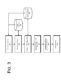
- Fig. 3 is a flowchart illustrating operations for creating a mission in a system for cabin airflow modeling according to embodiments.
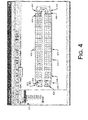
- Fig. 4 is a schematic illustration of an aircraft cabin layout, according to embodiments.
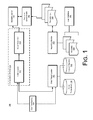
- Fig. 1 is a schematic illustration of a system 100 for cabin airflow modeling according to embodiments.
- the system 100 comprises multiple data stores, or databases, including a cabin template data store 110, and a logical object data store 112.
- the system 100 further comprises a configuration module 120, which in turn comprises a cabin layout module 122, and a script generator 124.
- the system 100 further comprises a modeling script 140, an execution environment 142, and one or more simulations 146.
- the system 100 further comprises a data parser/loader 150, a reporting module 152 capable of generating one or more reports 154 and may comprise a user interfaces 104, 160 to interact with components cabin template data store 110 may comprise data identifying cabin layouts for one or more particular vehicles.
- cabin template data store 110 may comprise one or more templates for layouts for a specific aircraft associated with aircraft data such as, e.g., an aircraft identifier, data pertaining to the aircraft operator, flight operations, and data related to one or more of the aircraft systems.
- the cabin layout module 122, the script generator module 124, the data parser/loader 150, and the reporting module 152 may be implemented as logic instructions stored on a computer readable medium and executable by a processor, e.g., software.
- the various data stores 110, 112 may be implemented as databases or as flat files stored on a computer readable medium.
- the cabin template 110 may be used to store various aircraft cabin layouts
- the logical object database 112 may be used to store logical objects which represent physical objects that reside in an aircraft cabin.
- logical objects may include fixtures such as seats, partitions, walls, stationary and mobile galley equipment, luggage equipment, occupants (i.e. passengers and crew), and the like.
- Logical objects may further include systems such as ventilation and airflow systems.
- Logical objects may further include human or animal objects.
- the data in databases 110 and 112 may be stored in a suitable computer readable storage medium, e.g., a magnetic storage medium, an optical storage medium, or combinations thereof.
- the modeling script 140 and the execution environment 142 may be embodied as modular components which are functionally separate from the configuration module 120.
- the modeling script 140 may be implemented as logic instructions encoded in a computer readable medium and executable on a processor.
- the execution environment 142 may comprise hardware and software on which the modeling script may be executed.
- the simulation(s) 146 may be used to simulate air flow modeling under varying cabin configurations and conditions in accordance with one or more predetermined models.
- the simulation(s) 146 may utilize parameters provided by a user of the system or derived from operational data for an aircraft fleet as inputs.
- the simulation(s) 146 may interface with a reporting module 152, which may create one or more reports 154 accessible via a user interface 160.
- system 200 may be implemented in a computer system environment.
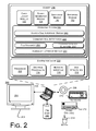
- Figure 2 is a schematic illustration of a computing system environment 200 which may be adapted to implement systems and methods for cabin airflow modeling in accordance with some embodiments.
- system 200 includes a computing device 208 and one or more accompanying input/output devices including a display 202 having a screen 204, one or more speakers 206, a keyboard 210, one or more other I/O device(s) 212, and a mouse 214.
- the other I/O device(s) 212 may include a touch screen, a voice-activated input device, a track ball, and any other device that allows the system 400 to receive input from a user.
- the computing device 208 includes system hardware 220 and memory 230, which may be implemented as random access memory and/or read-only memory.
- a file store 280 may be communicatively coupled to computing device 208.
- File store 280 may be internal to computing device 208 such as, e.g., one or more hard drives, CD-ROM drives, DVD-ROM drives, or other types of storage devices.
- File store 280 may also be external to computer 208 such as, e.g., one or more external hard drives, network attached storage, or a separate storage network.
- System hardware 220 may include one or more processors 222, a two graphics processor(s) 224, network interfaces 226, and bus structures 228.
- processors means any type of computational element, such as but not limited to, a microprocessor, a microcontroller, a complex instruction set computing (CISC) microprocessor, a reduced instruction set (RISC) microprocessor, a very long instruction word (VLIW) microprocessor, or any other type of processor or processing circuit.
- CISC complex instruction set computing
- RISC reduced instruction set
- VLIW very long instruction word
- Graphics processor(s) 224 may function as adjunct processors that manage graphics and/or video operations. Graphics processor(s) 224 may be integrated onto the motherboard of computing system 400 or may be coupled via an expansion slot on the motherboard.
- network interface 226 could be a wired interface such as an Ethernet interface (see, e.g., Institute of Electrical and Electronics Engineers/IEEE 802.3-2002) or a wireless interface such as an IEEE 802.11a, b or g-compliant interface (see, e.g., IEEE Standard for IT-Telecommunications and information exchange between systems LAN/MAN--Part II: Wireless LAN Medium Access Control (MAC) and Physical Layer (PHY) specifications Amendment 4: Further Higher Data Rate Extension in the 2.4 GHz Band, 802.11G-2003).
- GPRS general packet radio service
- Bus structures 228 connect various components of system hardware 228.
- bus structures 228 may be one or more of several types of bus structure(s) including a memory bus, a peripheral bus or external bus, and/or a local bus using any variety of available bus architectures including, but not limited to, 11-bit bus, Industrial Standard Architecture (ISA), Micro-Channel Architecture (MSA), Extended ISA (EISA), Intelligent Drive Electronics (IDE), VESA Local Bus (VLB), Peripheral Component Interconnect (PCI), Universal Serial Bus (USB), Advanced Graphics Port (AGP), Personal Computer Memory Card International Association bus (PCMCIA), and Small Computer Systems Interface (SCSI).
- ISA Industrial Standard Architecture
- MSA Micro-Channel Architecture
- EISA Extended ISA
- IDE Intelligent Drive Electronics
- VLB VESA Local Bus
- PCI Peripheral Component Interconnect
- USB Universal Serial Bus
- AGP Advanced Graphics Port
- PCMCIA Personal Computer Memory Card International Association bus
- SCSI Small Computer Systems Interface
- Memory 230 may include an operating system 240 for managing operations of computing device 208.
- operating system 240 includes a hardware interface module 254 that provides an interface to system hardware 220.
- operating system 240 may include a file system 250 that manages files used in the operation of computing device 208 and a process control subsystem 252 that manages processes executing on computing device 208.
- Operating system 240 may include (or manage) one or more communication interfaces that may operate in conjunction with system hardware 220 to transceive data packets and/or data streams from a remote source. Operating system 240 may further include a system call interface module 242 that provides an interface between the operating system 240 and one or more application modules resident in memory 230. Operating system 240 may be embodied as a Windows® brand operating system or as a UNIX operating system or any derivative thereof (e.g., Linux, Solaris, etc.), or other operating systems.
- the computing device 208 may be embodied as a computer system such as a personal computer, a laptop computer, a server, or another computing device.
- memory 230 includes a cabin layout module 122, a script generator module 124, one or more simulation modules 146, and a reporting module 152 to implement the operations described with reference to Fig. 3 .
- a data store is created which comprises one or more templates of a controlled cabin environment.
- the data store of cabin templates 110 may be populated with templates of cabin layouts for cabins of various aircraft.
- the cabin templates may define an empty cabin space.
- the templates may include preset cabin configuration features such as, e.g., specific seating layouts, lavatory locations, exit doors, cockpit configurations, galley layouts and configurations, and the like.
- the cabin layout templates may be stored in any type of data file structure in the cabin layout data store 110.
- an aircraft cabin may be selected.
- one or more aircraft types may be presented on a user interface 104 and one or more users of the system 100 may select an aircraft cabin from the choices presented on the user interface 104.
- the aircraft cabin template for the selected aircraft cabin may be retrieved from the data store and presented on the user interface for manipulation and configuration.
- a two-dimensional internal configuration for the selected aircraft is constructed.
- one or more logical objects may be retrieved from the logical object data store 112 and positioned in the cabin template selected in operation 310.
- the cabin configuration may define the dimensions of various cabin measurements and fixture such as exit doors 402.
- Logical objects may represent the lavatories 404, galley fixtures 406, first class seats 408 and economy seats 410. Additional logical objects may be added to represent overhead luggage compartments and airflow systems not visible in the floor plan view depicted in Fig. 4 .
- the various logical objects have physical properties associated with them.
- the objects may have physical dimensions and shapes associated with them.
- a user may specify one or more physical and material properties such as, e.g., airflow rates, angles, temperatures, heat flux parameters, viscosity and thermal conductivity of fluids, etc., associated with the objects.
- the various logical objects may be added to the template using a drag and drop technique.
- logical objects stored in the logical object data store 112 may be represented by icons which may be selected, dragged and dropped onto the template in desired positions and quantities.
- the system As the graphical user interface is populated the system generates a file structure 420 corresponding to the layout.
- a user of the system may populate one or more of the seats with a human object.
- a human object may have physical characteristics associated with it, e.g., height weight, shape, etc., and may have airflow characteristics associated with them.
- human objects may be assigned a mobile capability in which an object can move about aisles in the cabin.
- the user interface allows a user to generate a three-dimensional view of the cabin.
- the three dimensional view may be viewed from various perspectives to evaluate the cabin layout.
- the two-dimensional cabin layout may be used to generate a script for one or more three-dimensional cabin simulations.
- the script may include cabin geometry parameters and adequate boundary conditions for a computational fluid dynamics (CFD) pre-processor to generate a three-dimensional CFD model.
- the simulation may be executed using the CFD model.
- the system may implement one or more of a single-phase airflow and thermal simulation, a multiphase pathogen dispersion simulation, or a multi-species gas/vapor phase dispersion simulation.
- the simulation(s) may accommodate changing environmental conditions such as, e.g., changes in air temperature and pressure inside the cabin, breathing patterns of the occupants, movement of the occupants within the cabin, airflows throughout the cabin, and the like.
- results of the simulation may be presented to a user of the system.
- the simulations 146 may present one or more reports 154 via a reporting module 152.
- the reports 154 may be made accessible to a user via a user interface 160.
- a computer based system to generate a model for airflow dynamics in a controlled cabin environment, including: a data store 110 in a tangible computer readable memory 230 which stores a template 110 of the controlled cabin environment and a plurality of logical objects 112 which represent physical objects 402, 404, 406, 408, 410, wherein the logical objects 112 comprise airflow characteristics associated therewith; and a processor 222 to:
- the computer based system includes wherein the processor 222 executes the script 140 to implement a simulation 146 of airflow dynamics in the controlled cabin environment.
- the computer based system includes wherein the simulation 146 models airflow dynamics in the cabin using the airflow characteristics associated with the objects 112 and according to a predetermined model 140.
- the computer based system includes wherein the processor 222 generates a graphical user interface 104, 160 to allow a user to drag and drop one or more iconic representations of objects 112 into a cabin layout template 110.
- the computer based system includes wherein the iconic representations define an interior cabin configuration.
- a computer based method to model airflow dynamics in a controlled cabin environment, including creating a data store 110 including a template 110 of the controlled cabin environment and a plurality of logical objects 112 which represent physical objects 402, 404, 406, 408, 410, wherein the logical objects 112 comprise airflow characteristics associated therewith; constructing a two-dimensional layout of the cabin environment 315 from the template 110 and the plurality of logical objects 112; and generating, from the two-dimensional layout of the cabin environment 315, a script to construct a three-dimensional airflow model for the cabin environment 320.
- the computer based method includes wherein the data store 110 includes fixed objects 112, 402, 404, 406, 408, 410 and mobile objects 112 which move along one or more predetermined paths in the cabin environment in accordance with a predetermined model 140.
- the computer based method includes wherein the data store 112 comprises one or more human objects 112 which generate an airflow pattern in accordance with a predetermined model 140.
- the computer based method includes wherein creating a data store 110 including a template 110 of the controlled cabin environment comprises specifying at least one of a fluid flow rate and flow orientation in the cabin, a wall temperature, a heat flux parameter, and one or more dispersion sources.
- the computer based method includes further including executing the script 140 to implement a simulation 146 of airflow dynamics in the controlled cabin environment.
- the computer based method includes wherein the simulation 146 models airflow dynamics in the cabin using the airflow characteristics associated with the objects 112 and according to a predetermined model 140.
- the computer based method includes wherein constructing a two-dimensional layout of the cabin environment 315 includes utilizing a graphical user interface 104, 160 to drag and drop one or more iconic representations of objects 112 into a cabin layout template 110.
- the system enables a user to select a two-dimensional cabin template and design a cabin layout by populating the template with objects.
- the two-dimensional module may then be used to construct a three-dimensional CFD model, which may be input to a simulation processor.
- the acts described may be implemented by a computer, controller, processor, programmable device, firmware, or any other suitable device, and may be based on instructions stored on one or more computer-readable media or otherwise stored or programmed into such devices (e.g. including transmitting computer-readable instructions in real time to such devices).
- the acts described above may represent computer instructions that, when executed by one or more processors, perform the recited operations.
- the computer-readable media can be any available media that can be accessed by a device to implement the instructions stored thereon.
Landscapes
- Engineering & Computer Science (AREA)
- Physics & Mathematics (AREA)
- Theoretical Computer Science (AREA)
- General Physics & Mathematics (AREA)
- Geometry (AREA)
- General Engineering & Computer Science (AREA)
- Evolutionary Computation (AREA)
- Computer Hardware Design (AREA)
- Pure & Applied Mathematics (AREA)
- Mathematical Optimization (AREA)
- Mathematical Analysis (AREA)
- Computational Mathematics (AREA)
- Automation & Control Theory (AREA)
- Software Systems (AREA)
- Aviation & Aerospace Engineering (AREA)
- Health & Medical Sciences (AREA)
- Biomedical Technology (AREA)
- Fuzzy Systems (AREA)
- General Health & Medical Sciences (AREA)
- Molecular Biology (AREA)
- Life Sciences & Earth Sciences (AREA)
- Algebra (AREA)
- Artificial Intelligence (AREA)
- Data Mining & Analysis (AREA)
- Computing Systems (AREA)
- Mathematical Physics (AREA)
- Management, Administration, Business Operations System, And Electronic Commerce (AREA)
- Air Conditioning Control Device (AREA)
- Processing Or Creating Images (AREA)
Applications Claiming Priority (1)
| Application Number | Priority Date | Filing Date | Title |
|---|---|---|---|
| US13/421,056 US20130246008A1 (en) | 2012-03-15 | 2012-03-15 | Cabin airflow modeling |
Publications (1)
| Publication Number | Publication Date |
|---|---|
| EP2639719A1 true EP2639719A1 (en) | 2013-09-18 |
Family
ID=47740814
Family Applications (1)
| Application Number | Title | Priority Date | Filing Date |
|---|---|---|---|
| EP13154190.6A Ceased EP2639719A1 (en) | 2012-03-15 | 2013-02-06 | Cabin airflow modeling |
Country Status (5)
| Country | Link |
|---|---|
| US (1) | US20130246008A1 (enExample) |
| EP (1) | EP2639719A1 (enExample) |
| JP (1) | JP6055678B2 (enExample) |
| CA (1) | CA2801284C (enExample) |
| RU (1) | RU2637068C2 (enExample) |
Cited By (1)
| Publication number | Priority date | Publication date | Assignee | Title |
|---|---|---|---|---|
| RU2613850C1 (ru) * | 2016-02-05 | 2017-03-21 | Иван Владимирович Адерихин | Устройство для моделирования процессов функционирования экраноплана при эксплуатации |
Families Citing this family (5)
| Publication number | Priority date | Publication date | Assignee | Title |
|---|---|---|---|---|
| GB201217840D0 (en) * | 2012-08-13 | 2012-11-14 | Airbus Operations Ltd | System and method for computing design parameters for a thermally comfortable environment |
| EP2840485A1 (en) * | 2013-08-21 | 2015-02-25 | Airbus Operations GmbH | Aircraft with centralized generated and unified cabin control panel displays |
| US10181005B2 (en) * | 2015-10-09 | 2019-01-15 | The Boeing Company | Layout of passenger arrangements implementation using previously designed configurations |
| WO2022015739A1 (en) * | 2020-07-15 | 2022-01-20 | Thales Avionics, Inc. | Virus filtered/sterilized airflows directed to passengers in vehicle |
| CN116167292B (zh) * | 2022-12-28 | 2026-04-17 | 安徽宏元聚康医疗科技有限公司 | 一种基于仿真技术的代谢舱空气动力学结构设计方法 |
Citations (1)
| Publication number | Priority date | Publication date | Assignee | Title |
|---|---|---|---|---|
| US20050071138A1 (en) * | 2003-09-30 | 2005-03-31 | Conchi William R. | Method and system for seat placement |
Family Cites Families (41)
| Publication number | Priority date | Publication date | Assignee | Title |
|---|---|---|---|---|
| US6134511A (en) * | 1998-04-15 | 2000-10-17 | Subbarao; Krishnappa | Method and apparatus for improving building energy simulations |
| DE10041031A1 (de) * | 2000-08-22 | 2002-03-21 | Airbus Gmbh | Verfahren zur Konfiguration von Komponentenanordnungen und zur Generierung von Herstellungsunterlagen |
| US20020161563A1 (en) * | 2001-03-13 | 2002-10-31 | Naji Elabiad | System and method for performing vehicle interior configuration design |
| JP3851848B2 (ja) * | 2002-06-20 | 2006-11-29 | 株式会社東芝 | 流体と剛体の連携シミュレーション装置、流体と剛体の連携シミュレーションプログラム |
| US7206728B2 (en) * | 2002-09-25 | 2007-04-17 | Asahi Glass Company, Limited | Method for evaluating thermal comfort of a structure and an assisting method, program or system for designing a structure in consideration of thermal comfort |
| JPWO2004106009A1 (ja) * | 2003-06-02 | 2006-07-20 | 松下電器産業株式会社 | 物品取扱いシステムおよび物品取扱いサーバ |
| US20050055180A1 (en) * | 2003-09-08 | 2005-03-10 | Pischke Gina C. | Method and system for seat placement |
| US7529649B2 (en) * | 2004-03-18 | 2009-05-05 | The Boeing Company | System and method for knowledge based interior development |
| US8060345B2 (en) * | 2004-03-18 | 2011-11-15 | The Boeing Company | Transforming airplane configuration requirements into intelligent spatial geometry |
| US7690837B2 (en) * | 2006-03-07 | 2010-04-06 | The Boeing Company | Method of analysis of effects of cargo fire on primary aircraft structure temperatures |
| US7688199B2 (en) * | 2006-11-02 | 2010-03-30 | The Boeing Company | Smoke and fire detection in aircraft cargo compartments |
| US8016650B2 (en) * | 2006-12-12 | 2011-09-13 | The Boeing Company | Adjustable cabin nozzle |
| WO2008149135A1 (en) * | 2007-06-04 | 2008-12-11 | Bae Systems Plc | Indexing and compression of results of computational fluid dynamics simulations |
| US8065122B2 (en) * | 2007-07-16 | 2011-11-22 | Durr Systems, Inc. | Method of designing or evaluating a bake oven |
| DE102007049926A1 (de) * | 2007-10-18 | 2009-04-23 | Airbus Deutschland Gmbh | System und Verfahren zur Klimatisierung zumindest eines Teilbereichs eines Flugzeugs |
| US9070299B2 (en) * | 2007-12-21 | 2015-06-30 | Airbus Operations Gmbh | Arrangement comprising a mock-up for reproducing and testing an aircraft passenger cabin |
| US8577650B2 (en) * | 2008-02-26 | 2013-11-05 | Kimberly-Clark Worldwide, Inc. | User interface for modeling thermal comfort |
| US8306794B2 (en) * | 2008-06-26 | 2012-11-06 | International Business Machines Corporation | Techniques for thermal modeling of data centers to improve energy efficiency |
| US20100081369A1 (en) * | 2008-09-30 | 2010-04-01 | Space David R | Personal ventilation in an aircraft environment |
| US10029797B2 (en) * | 2008-09-30 | 2018-07-24 | The Boeing Company | Personal ventilation in an aircraft environment |
| US8473265B2 (en) * | 2008-10-27 | 2013-06-25 | Schneider Electric It Corporation | Method for designing raised floor and dropped ceiling in computing facilities |
| US9904331B2 (en) * | 2009-04-01 | 2018-02-27 | Schneider Electric It Corporation | Method for computing cooling redundancy at the rack level |
| FR2947771B1 (fr) * | 2009-07-08 | 2011-10-21 | Airbus Operations Sas | Procede et dispositif d'amenagement de cabine passager |
| US20110282637A1 (en) * | 2009-07-08 | 2011-11-17 | Livermore Software Technology Corporation | Numerical simulation of airflow within porous materials |
| EP2287758A1 (en) * | 2009-07-14 | 2011-02-23 | Airbus Engineering Centre India | System and method for numerically evaluating thermal comfort inside an enclosure |
| DE102009040731A1 (de) * | 2009-09-09 | 2011-03-17 | Airbus Operations Gmbh | Konfigurationsgesteuerte dynamische Erzeugung von Produktdaten für komplexe Produkte |
| DE102009043327B4 (de) * | 2009-09-28 | 2017-11-23 | Airbus Operations Gmbh | System und Verfahren zur Konfiguration einer Flugzeugpassagierkabine |
| DE102009043314B4 (de) * | 2009-09-28 | 2018-12-20 | Airbus Operations Gmbh | Kabinenausstattungskomponentenanschlusssystem und Verfahren zur Modifikation einer Passagierkabinenkonfiguration |
| DE102009058802B4 (de) * | 2009-12-18 | 2018-03-29 | Airbus Operations Gmbh | Anordnung zur kombinierten Darstellung eines realen und eines virtuellen Modells |
| US8510086B1 (en) * | 2010-01-28 | 2013-08-13 | The Boeing Company | Aircraft passenger flow system |
| DE102010021638A1 (de) * | 2010-04-14 | 2011-10-20 | Airbus Operations Gmbh | Verfahren zur Konfiguration und/oder Bestückung einer Kabine eines Luftfahrzeugs |
| US20120072181A1 (en) * | 2010-09-22 | 2012-03-22 | Behzad Imani | Method and apparatus for optimizing hvac systems in buildings |
| US8630830B1 (en) * | 2010-10-11 | 2014-01-14 | The Boeing Company | Thermal analysis system |
| US9223905B2 (en) * | 2011-03-25 | 2015-12-29 | Schneider Electric It Corporation | Systems and methods for predicting fluid dynamics in a data center |
| US8967173B2 (en) * | 2011-08-24 | 2015-03-03 | The Boeing Company | System and methods for ground-based cabin/cargo pressurization/depressurization |
| US20130147786A1 (en) * | 2011-12-08 | 2013-06-13 | Mattew Ross SMITH | Method and apparatus for executing high performance computation to solve partial differential equations and for outputting three-dimensional interactive images in collaboration with graphic processing unit, computer readable recording medium, and computer program product |
| CH706502A2 (fr) * | 2012-05-11 | 2013-11-15 | Hygie Tech Sa C O Bureau Fiduciaire Georges Alain Zufferey Sarl | Procédé et système informatisé de modélisation des flux aérauliques notamment pour l'évaluation quantitative du risque de contamination aéroportée. |
| US10157245B2 (en) * | 2012-10-31 | 2018-12-18 | Schneider Electric It Corporation | System and method for fluid dynamics prediction with an enhanced potential flow model |
| US9797802B2 (en) * | 2013-03-04 | 2017-10-24 | Jay White | Virtual testing model for use in simulated aerodynamic testing |
| US20140248827A1 (en) * | 2013-03-04 | 2014-09-04 | The Boeing Company | Aircraft Circulation System for Passenger Cabins |
| EP2784704A1 (en) * | 2013-03-26 | 2014-10-01 | Fujitsu Limited | Multi-component computational fluid dynamics simulations |
-
2012
- 2012-03-15 US US13/421,056 patent/US20130246008A1/en not_active Abandoned
-
2013
- 2013-01-07 JP JP2013000446A patent/JP6055678B2/ja active Active
- 2013-01-09 CA CA2801284A patent/CA2801284C/en active Active
- 2013-02-06 EP EP13154190.6A patent/EP2639719A1/en not_active Ceased
- 2013-03-14 RU RU2013111508A patent/RU2637068C2/ru active
Patent Citations (1)
| Publication number | Priority date | Publication date | Assignee | Title |
|---|---|---|---|---|
| US20050071138A1 (en) * | 2003-09-30 | 2005-03-31 | Conchi William R. | Method and system for seat placement |
Non-Patent Citations (2)
| Title |
|---|
| JÖRG FUCHTE ET AL: "Rapid Creation of CFD-Capable CAD-Modles for Cabin Air Ventilation Simulation", 31 March 2011 (2011-03-31), Hamburg, Germany, XP055065162, Retrieved from the Internet <URL:http://cgi.tu-harburg.de/~iltwww/files/ast2011_fuchte_rajkowski_wick.pdf> [retrieved on 20130604] * |
| WIKIPEDIA: "Drag and drop", 27 July 2011 (2011-07-27), XP055259630, Retrieved from the Internet <URL:https://en.wikipedia.org/w/index.php?title=Drag_and_drop&oldid=441645676> [retrieved on 20160318] * |
Cited By (1)
| Publication number | Priority date | Publication date | Assignee | Title |
|---|---|---|---|---|
| RU2613850C1 (ru) * | 2016-02-05 | 2017-03-21 | Иван Владимирович Адерихин | Устройство для моделирования процессов функционирования экраноплана при эксплуатации |
Also Published As
| Publication number | Publication date |
|---|---|
| JP2013232176A (ja) | 2013-11-14 |
| JP6055678B2 (ja) | 2016-12-27 |
| RU2013111508A (ru) | 2014-09-20 |
| CA2801284A1 (en) | 2013-09-15 |
| RU2637068C2 (ru) | 2017-11-29 |
| US20130246008A1 (en) | 2013-09-19 |
| CA2801284C (en) | 2016-07-26 |
Similar Documents
| Publication | Publication Date | Title |
|---|---|---|
| CA2801284C (en) | Cabin airflow modeling | |
| US9261874B2 (en) | Method for configuration and/or equipment of a vehicle cabin, in particular of an aircraft | |
| Zhang et al. | Novel air distribution systems for commercial aircraft cabins | |
| CN104102760B (zh) | 用于三维可视化的定位系统 | |
| US8170843B2 (en) | Generic hard/soft 3D spatial collision detection method | |
| EP2994266A2 (en) | Shop order status visualization system | |
| Forlingieri | The four dimensions of Variability and their impact on MBPLE: How to approach variability in the development of aircraft product lines at Airbus | |
| US20140365943A1 (en) | Serial Number Control Visualization System | |
| Polacsek et al. | Towards thinking manufacturing and design together: An aeronautical case study | |
| US11080447B2 (en) | System and part design based on structured requirements | |
| Butler et al. | Optimising the locations of thermally sensitive equipment in an aircraft crown compartment | |
| EP2990894A2 (en) | Serial number control visualization system | |
| Aranjo et al. | Performance investigation of ground cooling for the airbus A380 in the United Arab Emirates | |
| Walther | Knowledge-based engineering to provide aircraft fuselage design details for multidisciplinary and multifidelity analysis model generation | |
| JP6288937B2 (ja) | 航空機導線レイアウト検証システム | |
| Broehan et al. | Seamless Transitions from Logical to Physical Avionics Architecture Models for Preliminary Aircraft Systems Design | |
| Liu et al. | Analysis of multiple dynamic simulation methods applied inthestudy of flow field in subwaytunnels | |
| Bamrah et al. | Zonal Safety and Particular Risk Analysis for Aircraft Conceptual Design | |
| Safadi et al. | Overview and Perspectives of Air Mobility Operations and Simulation Tools | |
| Tian et al. | Virtual simulation-based evaluation of ground handling for future aircraft concepts | |
| Vankan et al. | Optimization tool for equipment placement and routing in more electric aircraft | |
| Guo et al. | Research on evaluation of cabin design based on virtual reality | |
| Li | Multi-objective design optimization for high-lift aircraft configurations supported by surrogate modeling | |
| Peddada | A two-stage design framework for optimal spatial packaging of interconnected fluid-thermal systems | |
| Eckhardt et al. | Computer simulation helps keep down costs for NASA's “lifeboat” for the international space station |
Legal Events
| Date | Code | Title | Description |
|---|---|---|---|
| PUAI | Public reference made under article 153(3) epc to a published international application that has entered the european phase |
Free format text: ORIGINAL CODE: 0009012 |
|
| 17P | Request for examination filed |
Effective date: 20130206 |
|
| AK | Designated contracting states |
Kind code of ref document: A1 Designated state(s): AL AT BE BG CH CY CZ DE DK EE ES FI FR GB GR HR HU IE IS IT LI LT LU LV MC MK MT NL NO PL PT RO RS SE SI SK SM TR |
|
| AX | Request for extension of the european patent |
Extension state: BA ME |
|
| 17Q | First examination report despatched |
Effective date: 20171011 |
|
| STAA | Information on the status of an ep patent application or granted ep patent |
Free format text: STATUS: THE APPLICATION HAS BEEN REFUSED |
|
| 18R | Application refused |
Effective date: 20191116 |