EP2639686A2 - Input control device, input control program, and input control method - Google Patents
Input control device, input control program, and input control method Download PDFInfo
- Publication number
- EP2639686A2 EP2639686A2 EP12197752.4A EP12197752A EP2639686A2 EP 2639686 A2 EP2639686 A2 EP 2639686A2 EP 12197752 A EP12197752 A EP 12197752A EP 2639686 A2 EP2639686 A2 EP 2639686A2
- Authority
- EP
- European Patent Office
- Prior art keywords
- threshold
- unit
- detection target
- input
- input control
- Prior art date
- Legal status (The legal status is an assumption and is not a legal conclusion. Google has not performed a legal analysis and makes no representation as to the accuracy of the status listed.)
- Withdrawn
Links
Images



Classifications
-
- G—PHYSICS
- G06—COMPUTING OR CALCULATING; COUNTING
- G06F—ELECTRIC DIGITAL DATA PROCESSING
- G06F3/00—Input arrangements for transferring data to be processed into a form capable of being handled by the computer; Output arrangements for transferring data from processing unit to output unit, e.g. interface arrangements
- G06F3/01—Input arrangements or combined input and output arrangements for interaction between user and computer
- G06F3/03—Arrangements for converting the position or the displacement of a member into a coded form
- G06F3/041—Digitisers, e.g. for touch screens or touch pads, characterised by the transducing means
-
- G—PHYSICS
- G06—COMPUTING OR CALCULATING; COUNTING
- G06F—ELECTRIC DIGITAL DATA PROCESSING
- G06F3/00—Input arrangements for transferring data to be processed into a form capable of being handled by the computer; Output arrangements for transferring data from processing unit to output unit, e.g. interface arrangements
- G06F3/01—Input arrangements or combined input and output arrangements for interaction between user and computer
- G06F3/048—Interaction techniques based on graphical user interfaces [GUI]
- G06F3/0487—Interaction techniques based on graphical user interfaces [GUI] using specific features provided by the input device, e.g. functions controlled by the rotation of a mouse with dual sensing arrangements, or of the nature of the input device, e.g. tap gestures based on pressure sensed by a digitiser
- G06F3/0488—Interaction techniques based on graphical user interfaces [GUI] using specific features provided by the input device, e.g. functions controlled by the rotation of a mouse with dual sensing arrangements, or of the nature of the input device, e.g. tap gestures based on pressure sensed by a digitiser using a touch-screen or digitiser, e.g. input of commands through traced gestures
- G06F3/04886—Interaction techniques based on graphical user interfaces [GUI] using specific features provided by the input device, e.g. functions controlled by the rotation of a mouse with dual sensing arrangements, or of the nature of the input device, e.g. tap gestures based on pressure sensed by a digitiser using a touch-screen or digitiser, e.g. input of commands through traced gestures by partitioning the display area of the touch-screen or the surface of the digitising tablet into independently controllable areas, e.g. virtual keyboards or menus
Definitions
- the embodiments discussed herein are related to an input control device, an input control program, and an input control method.
- the touch panel has both an input function and a display function.
- the user causes the electronic equipment to execute a process corresponding to a selection object by touching the "selection object", such as a button displayed on the touch panel.
- the electronic equipment such as mobile terminals, has been miniaturized. Therefore, in a case where many items of information are displayed on the touch panel of the miniaturized electronic equipment, the size of the displayed selection objects is reduced. This induces the user to make an erroneous input.
- conventionally electronic equipment with two different sensors has been proposed which detects a contact-predetermined position with a first sensor before a detection target such as user's finger comes into touch with the touch panel, and displays an image around the contact-predetermined position in an enlarged manner. In such electronic equipment, detection of a position in the touch panel with which the detection target comes into touch is carried out with a second sensor.
- Patent Document 1 Japanese Laid-open Patent Publication No. 2009-3867
- Patent Document 2 Japanese Laid-open Patent Publication No. 2011-22961
- an object in one aspect of an embodiment of the invention to provide an input control device, an input control program, and an input control method that are capable of simplifying the configuration of equipment and improve the operability of the equipment.
- an input control device includes an acquisition unit that acquires a sensing value that varies depending on a distance between a detection target and an input unit and sensed by a sensing device included in the input unit; a detection unit that detects the detection target based on the acquired sensing value and a threshold selected from among a first threshold corresponding to a first sensing area and a second threshold corresponding to a second sensing area having a shorter distance from the input unit than the first area; a display control unit that enlarges an image displayed on a display unit when the first threshold is set and the detection target is detected; and a setting unit that sets the second threshold instead of the first threshold when the first threshold is set and the detection target is detected.
- the input control device, the input control program, and the input control method disclosed by the present application are not limited by the embodiments.
- configurations having the same function are denoted like reference signs and description thereof is not repeated.
- FIG. 1 is a block diagram illustrating an example of an input control device of a first embodiment.
- an input control device 10 includes an acquisition unit 11, a detection unit 12, a setting unit 13, and a display control unit 14.
- the acquisition unit 11 acquires a sensing value sensed by a sensing device included in an input unit (not illustrated) with a predetermined period.
- the sensing value is a value that varies depending on the distance between a detection target and the input unit.
- the acquired sensing value is output to the detection unit 12.
- the input unit and the display unit described below are one touch panel, for example.
- the sensing device includes an insulating film, an electrode layer underlying the insulating film, and a substrate layer to mount a control IC thereon when the touch panel has an electrostatic system.
- the detection unit 12 detects the detection target, based on the sensing value received from the acquisition unit 11 and a threshold set by the setting unit 13.
- the detection target is usually user's finger or a pointing device used for an input operation.
- the threshold which is preset is one of a first threshold corresponding to a first sensing area, and a second threshold corresponding to a second sensing area.
- the distance from the input unit to the first sensing area is longer than the distance from the input unit to the second sensing area. That is, the detection unit 12 can sense that the detection target is present within a range of a distance D1 from the input unit when the first threshold is set, and can sense that the detection unit is present in a range of a distance D2 (D2 ⁇ D1) from the input unit when the second threshold is set. That is, the state in which the first threshold is set is referred to as a "high sensitivity state", and the state in which the second threshold is set is referred to as a "low sensitivity state.”
- the result of the detection by the detection unit 12 is output to the setting unit 13 and the display control unit 14.
- the setting unit 13 sets the threshold to be used by the detection unit 12.
- the setting unit 13 selects the first threshold as an initial value.
- the setting unit 13 selects the second threshold. After the second threshold is set and the detection target is detected, the setting unit 13 selects the first threshold.
- the setting unit 13 stores a threshold table in which identification numbers of the first threshold and the second threshold and the values of the thresholds according to each identification number are associated.
- the setting unit 13 outputs the identification number and the value of the selected threshold to the detection unit 12 and the display control unit 14.
- FIG. 2 is a diagram illustrating the threshold table of the first embodiment.
- the display control unit 14 outputs, to the display unit, a control signal for enlarging an image displayed on the display unit when the first threshold is set and the detection target is detected.
- the display control unit 14 outputs, to the display unit, a control signal for canceling the enlarged state of the image displayed on the display unit when the second threshold is set and the detection target is detected.
- the display control unit 14 may output, to the display unit, the control signal for canceling the enlarged state of the image displayed on the display unit when the detection target is not detected even though predetermined time passes after the image is displayed in an enlarged manner as well as when the second threshold is set and the detection target is detected.
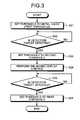
- FIG. 3 is a flowchart illustrating an example of a processing operation of the input control device 10 of the first embodiment.
- the setting unit 13 sets the first threshold as an initial value (Step S21).
- the setting unit 13 determines whether the detection target is detected, based on the detection result, which is based on the latest sensing value detected by the detection unit 12, and the first threshold (Step S22). This determination is repeated until the detection target is detected (No in Step S22).
- Step S22 When it is determined that the detection target is detected (Yes in Step S22), the setting unit 13 sets the second threshold instead of the first threshold (Step S23). As a result, the high sensitivity state is switched to the low sensitivity state.
- Step S24 When it is determined that the detection target is detected (Yes in Step S22), the display control unit 14 performs display enlarging control (Step S24).
- the display enlarging control is carried out by outputting, to the display unit, the control signal for expanding the image displayed on the display unit.
- the display enlarging control for example, a portion of the image displayed on the display unit is enlarged and displayed.
- the setting unit 13 determines whether the detection target is detected, based on the detection result which is based on the latest sensing value detected by the detection unit 12 and the second threshold (Step S25). This determination is repeated until the detection target is detected (No in Step S25).
- Step S25 When it is determined that the detection target is detected (Yes in Step S25), the setting unit 13 sets the first threshold instead of the second threshold (Step S26). As a result, the low sensitivity state is switched to the high sensitivity state.
- Step S25 may be terminated by a time-out method, that is, when predetermined time passes after the image is enlarged and displayed. That is, when the detection target is not detected in predetermined time after the second threshold is set, the setting unit 13 may output a canceling instruction of canceling the enlarged display to the display control unit 14 and may set the first threshold instead of the second threshold.
- the detection unit 12 detects the detection target in the input control device 10. This detection is carried out based on the sensing value acquired by the acquisition unit 11, and the threshold set by selecting either the first threshold corresponding to the first sensing area and the second threshold corresponding to the second sensing area having a shorter distance from the input unit than the first sensing area.
- the display control unit 14 enlarges the image displayed on the display unit and the setting unit 13 sets the second threshold instead of the first threshold.
- a contact-predetermined position is calculated in a high sensitivity state, and a selection object which is present in a search range including the contact-predetermined position is enlarged and displayed.
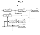
- FIG. 4 is a block diagram illustrating an example of an input control device of the second embodiment.
- an input control device 30 includes a calculation unit 31, a search unit 32, a display control unit 33, and a specification unit 34.
- the calculation unit 31 calculates a contact-predetermined position of a detection target in an input unit, based on a sensing value received from the acquisition unit 11. Specifically, in the high sensitivity state, the calculation unit 31 receives a plurality of coordinates on the screen of the input unit, that is, the screen of a touch panel, and sensing values detected by a sensor which correspond to the respective coordinates, and calculates the coordinates (XMAX, YMAX) with the largest sensing value as the contact-predetermined position.
- the calculation unit 31 calculates a contact position of the detection target in the input unit, based on the sensing value received from the acquisition unit 11. Specifically, in the low sensitivity state, the calculation unit 31 receives a plurality of coordinates on the screen of the input unit, that is, the screen of the touch panel, and sensing values detected by the sensor which correspond to the respective coordinates, and calculates the coordinates (X' MAX , Y' MAX ) with the largest sensing value as the contact position.
- the search unit 32 sets a "search range" including the contact-predetermined position calculated by the calculation unit 31. Specifically, the search unit 32 sets a rectangle having apexes (X MAX - a, Y MAX - b), (X MAX + a, Y MAX - b), (X MAX - a, Y MAX + b), and (X MAX + a, Y MAX + b) as the search range.
- the values "a” and "b” may be values equal to each other or values different from each other.
- the search unit 32 searches for a selection object within the search range. This search process is performed over the entire search range.
- the selection object is a button or a hyperlink text.
- the display control unit 33 enlarges and displays the selection object searched by the search unit 32 when the first threshold is set and the detection target is detected.
- the selection object may be enlarged and displayed regardless of the number of searched selection objects, or the selection object may be enlarged and displayed only when there are a predetermined number of selection objects.
- the specification unit 34 specifies the selection object as an execution subject when a position in the display unit corresponding to a contact position calculated by the calculation unit 31 agrees with a display position of the selection object searched by the search unit 32.
- the information on a specified execution target is output to a processor (not illustrated), and a process corresponding to the execution target is executed by the processor.
- the specification unit 34 outputs information which signifies that the execution target has been specified, to the setting unit 13. By receiving this information, the setting unit 13 sets the first threshold instead of the second threshold.
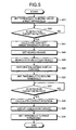
- FIG. 5 is a flowchart illustrating an example of a processing operation of the input control device 30 of the second embodiment.
- FIG. 6 is a diagram to describe the processing operation of the input control device 30 of the second embodiment.
- the setting unit 13 sets the first threshold as an initial value (Step S21) like in the flowchart of FIG. 3 . Subsequently, the setting unit 13 determines whether the detection target is detected, based on the detection result which is based on the latest sensing value detected by the detection unit 12 and the first threshold (Step S22). In FIG. 6(A) , since a finger which is a detection target is not yet detected, a display image is not yet expanded, either.
- the calculation unit 31 calculates a contact-predetermined position of the detection target in the input unit based on the sensing value received from the acquisition unit 11 in the high sensitivity state (Step S41). In FIG. 6(B) , the finger which is a detection target is detected and the contact-predetermined position of the finger is calculated.
- the search unit 32 sets a search range including the contact-predetermined position calculated by the calculation unit 31 (Step S42), and searches for the selection object being present in the search range (Step S43).
- the display control unit 33 enlarges and displays the selection object searched by the search unit 32 (Step S44).
- the hyperlink texts "area”, “Hokkaido”, “northeast”, and “Kanto” which are searched within the search range are enlarged and displayed.
- Step S22 When it is determined that the detection target is detected in the high sensitivity state (Yes in Step S22), the setting unit 13 sets the second threshold instead of the first threshold (Step S23).
- the calculation unit 31 calculates a contact position of the detection target in the input unit based on the sensing value received from the acquisition unit 11 in the high sensitivity state (Step S45). In FIG. 6(C) , the finger which is a detection target is detected and the contact position of the finger is calculated.
- the specification unit 34 specifies the selection object as an execution target (Step S46). Since the position in the display unit corresponding to the contact position agrees with the display position of the hyperlink text "Tohoku" in FIG. 6(C) , the news of the Tohoku district is displayed in FIG. 6(D) .
- the calculation unit 31 calculates the contact-predetermined position of the detection target in the input unit, based on the sensing value acquired at detection timing determined based on the first threshold. Subsequently, the search unit 32 searches, for the selection object, in the search range including the position in the display unit corresponding to the contact-predetermined position. Subsequently, the display control unit 33 enlarges and displays the selection object searched by the search unit 32.
- the calculation unit 31 calculates the contact position of the detection target in the input unit based on the sensing value acquired at the detection timing determined based on the second threshold.
- the specification unit 34 specifies the selection object as an execution target.
- operability of equipment can be improved and the configuration of equipment can be simplified.
Landscapes
- Engineering & Computer Science (AREA)
- General Engineering & Computer Science (AREA)
- Theoretical Computer Science (AREA)
- Human Computer Interaction (AREA)
- Physics & Mathematics (AREA)
- General Physics & Mathematics (AREA)
- User Interface Of Digital Computer (AREA)
- Position Input By Displaying (AREA)
Abstract
Description
- The embodiments discussed herein are related to an input control device, an input control program, and an input control method.
- In recent years, electronic equipment with a touch panel, such as a mobile terminal, has widely spread. The touch panel has both an input function and a display function. The user causes the electronic equipment to execute a process corresponding to a selection object by touching the "selection object", such as a button displayed on the touch panel.
- The electronic equipment, such as mobile terminals, has been miniaturized. Therefore, in a case where many items of information are displayed on the touch panel of the miniaturized electronic equipment, the size of the displayed selection objects is reduced. This induces the user to make an erroneous input. In order to avoid this and improve the operability, conventionally electronic equipment with two different sensors has been proposed which detects a contact-predetermined position with a first sensor before a detection target such as user's finger comes into touch with the touch panel, and displays an image around the contact-predetermined position in an enlarged manner. In such electronic equipment, detection of a position in the touch panel with which the detection target comes into touch is carried out with a second sensor.
- Moreover, electronic equipment of another type also has been proposed. This electronic equipment includes an input control device enabling two kinds of operations, that is, a touch operation in which a finger or the like comes in direct touch with the touch panel and a spatial operation which does not require direct touch with the touch panel by being provided with two sensors different in sensitivity.
Patent Document 1: Japanese Laid-open Patent Publication No.2009-3867
Patent Document 2: Japanese Laid-open Patent Publication No.2011-22961 - However, the configuration of the conventional electronic equipment is complicated because it is equipped with two sensors.
- Accordingly, it is an object in one aspect of an embodiment of the invention to provide an input control device, an input control program, and an input control method that are capable of simplifying the configuration of equipment and improve the operability of the equipment.
- According to an aspect of an embodiment, an input control device includes an acquisition unit that acquires a sensing value that varies depending on a distance between a detection target and an input unit and sensed by a sensing device included in the input unit; a detection unit that detects the detection target based on the acquired sensing value and a threshold selected from among a first threshold corresponding to a first sensing area and a second threshold corresponding to a second sensing area having a shorter distance from the input unit than the first area; a display control unit that enlarges an image displayed on a display unit when the first threshold is set and the detection target is detected; and a setting unit that sets the second threshold instead of the first threshold when the first threshold is set and the detection target is detected.
-
-
FIG. 1 is a block diagram illustrating an example of an input control device of a first embodiment; -
FIG. 2 is a diagram illustrating a threshold table of the first embodiment; -
FIG. 3 is a flowchart illustrating an example of a processing operation of the input control device of the first embodiment; -
FIG. 4 is a block diagram illustrating an example of an input control device of a second embodiment; -
FIG. 5 is a flowchart illustrating an example of a processing operation of the input control device of the second embodiment; -
FIG. 6 is a diagram to describe the processing operation of the input control device of the second embodiment; -
FIG. 7 is an explanatory diagram illustrating a computer which executes an input control program; and -
FIG. 8 is a diagram illustrating an example of a software configuration. - Preferred embodiments of the present invention will be explained with reference to accompanying drawings.
- The input control device, the input control program, and the input control method disclosed by the present application are not limited by the embodiments. In the embodiments, configurations having the same function are denoted like reference signs and description thereof is not repeated.
-
FIG. 1 is a block diagram illustrating an example of an input control device of a first embodiment. Referring toFIG. 1 , aninput control device 10 includes anacquisition unit 11, adetection unit 12, asetting unit 13, and adisplay control unit 14. - The
acquisition unit 11 acquires a sensing value sensed by a sensing device included in an input unit (not illustrated) with a predetermined period. The sensing value is a value that varies depending on the distance between a detection target and the input unit. The acquired sensing value is output to thedetection unit 12. Here, the input unit and the display unit described below are one touch panel, for example. The sensing device includes an insulating film, an electrode layer underlying the insulating film, and a substrate layer to mount a control IC thereon when the touch panel has an electrostatic system. - The
detection unit 12 detects the detection target, based on the sensing value received from theacquisition unit 11 and a threshold set by thesetting unit 13. The detection target is usually user's finger or a pointing device used for an input operation. - Specifically, the threshold which is preset is one of a first threshold corresponding to a first sensing area, and a second threshold corresponding to a second sensing area. The distance from the input unit to the first sensing area is longer than the distance from the input unit to the second sensing area. That is, the
detection unit 12 can sense that the detection target is present within a range of a distance D1 from the input unit when the first threshold is set, and can sense that the detection unit is present in a range of a distance D2 (D2 < D1) from the input unit when the second threshold is set. That is, the state in which the first threshold is set is referred to as a "high sensitivity state", and the state in which the second threshold is set is referred to as a "low sensitivity state." - The result of the detection by the
detection unit 12 is output to thesetting unit 13 and thedisplay control unit 14. - The
setting unit 13 sets the threshold to be used by thedetection unit 12. - Specifically, the
setting unit 13 selects the first threshold as an initial value. When the first threshold is set to be used by thedetection unit 12 and the detection target is detected, thesetting unit 13 selects the second threshold. After the second threshold is set and the detection target is detected, thesetting unit 13 selects the first threshold. - The
setting unit 13 stores a threshold table in which identification numbers of the first threshold and the second threshold and the values of the thresholds according to each identification number are associated. Thesetting unit 13 outputs the identification number and the value of the selected threshold to thedetection unit 12 and thedisplay control unit 14.FIG. 2 is a diagram illustrating the threshold table of the first embodiment. When the input unit is an electrostatic-type touch panel and the sensing value is capacitance between electrodes, the relation "V1 < V2" is established inFIG. 2 . - The
display control unit 14 outputs, to the display unit, a control signal for enlarging an image displayed on the display unit when the first threshold is set and the detection target is detected. Thedisplay control unit 14 outputs, to the display unit, a control signal for canceling the enlarged state of the image displayed on the display unit when the second threshold is set and the detection target is detected. Thedisplay control unit 14 may output, to the display unit, the control signal for canceling the enlarged state of the image displayed on the display unit when the detection target is not detected even though predetermined time passes after the image is displayed in an enlarged manner as well as when the second threshold is set and the detection target is detected. - Operation of the
input control device 10 having the above-described configuration will be described. -
FIG. 3 is a flowchart illustrating an example of a processing operation of theinput control device 10 of the first embodiment. - The
setting unit 13 sets the first threshold as an initial value (Step S21). - The
setting unit 13 determines whether the detection target is detected, based on the detection result, which is based on the latest sensing value detected by thedetection unit 12, and the first threshold (Step S22). This determination is repeated until the detection target is detected (No in Step S22). - When it is determined that the detection target is detected (Yes in Step S22), the
setting unit 13 sets the second threshold instead of the first threshold (Step S23). As a result, the high sensitivity state is switched to the low sensitivity state. - When it is determined that the detection target is detected (Yes in Step S22), the
display control unit 14 performs display enlarging control (Step S24). The display enlarging control is carried out by outputting, to the display unit, the control signal for expanding the image displayed on the display unit. With the display enlarging control, for example, a portion of the image displayed on the display unit is enlarged and displayed. - Subsequently, the setting
unit 13 determines whether the detection target is detected, based on the detection result which is based on the latest sensing value detected by thedetection unit 12 and the second threshold (Step S25). This determination is repeated until the detection target is detected (No in Step S25). - When it is determined that the detection target is detected (Yes in Step S25), the setting
unit 13 sets the first threshold instead of the second threshold (Step S26). As a result, the low sensitivity state is switched to the high sensitivity state. - The determination in Step S25 may be terminated by a time-out method, that is, when predetermined time passes after the image is enlarged and displayed. That is, when the detection target is not detected in predetermined time after the second threshold is set, the setting
unit 13 may output a canceling instruction of canceling the enlarged display to thedisplay control unit 14 and may set the first threshold instead of the second threshold. - As described above, according to the embodiment, the
detection unit 12 detects the detection target in theinput control device 10. This detection is carried out based on the sensing value acquired by theacquisition unit 11, and the threshold set by selecting either the first threshold corresponding to the first sensing area and the second threshold corresponding to the second sensing area having a shorter distance from the input unit than the first sensing area. When the first threshold is set and the detection target is detected, thedisplay control unit 14 enlarges the image displayed on the display unit and thesetting unit 13 sets the second threshold instead of the first threshold. - With this operation, since the enlarged state can be maintained unchanged until the detection target comes further closer to the input unit, the erroneous input by the user can be prevented. As a result, the operability of the input unit may be improved. Moreover, since two kinds of detections, high sensitivity and low sensitivity detections, can be achieved with a single input unit by switching between thresholds, the configuration of equipment can be simplified.
- In a second embodiment, a contact-predetermined position is calculated in a high sensitivity state, and a selection object which is present in a search range including the contact-predetermined position is enlarged and displayed.
-
FIG. 4 is a block diagram illustrating an example of an input control device of the second embodiment. Referring toFIG. 4 , aninput control device 30 includes acalculation unit 31, asearch unit 32, a display control unit 33, and aspecification unit 34. - At detection timing determined based on a first threshold, that is, during the high sensitivity state, the
calculation unit 31 calculates a contact-predetermined position of a detection target in an input unit, based on a sensing value received from theacquisition unit 11. Specifically, in the high sensitivity state, thecalculation unit 31 receives a plurality of coordinates on the screen of the input unit, that is, the screen of a touch panel, and sensing values detected by a sensor which correspond to the respective coordinates, and calculates the coordinates (XMAX, YMAX) with the largest sensing value as the contact-predetermined position. - At detection timing determined based on a second threshold, that is, during a low sensitivity state, the
calculation unit 31 calculates a contact position of the detection target in the input unit, based on the sensing value received from theacquisition unit 11. Specifically, in the low sensitivity state, thecalculation unit 31 receives a plurality of coordinates on the screen of the input unit, that is, the screen of the touch panel, and sensing values detected by the sensor which correspond to the respective coordinates, and calculates the coordinates (X'MAX, Y'MAX) with the largest sensing value as the contact position. - The
search unit 32 sets a "search range" including the contact-predetermined position calculated by thecalculation unit 31. Specifically, thesearch unit 32 sets a rectangle having apexes (XMAX - a, YMAX - b), (XMAX + a, YMAX - b), (XMAX - a, YMAX + b), and (XMAX + a, YMAX + b) as the search range. The values "a" and "b" may be values equal to each other or values different from each other. - The
search unit 32 searches for a selection object within the search range. This search process is performed over the entire search range. Here, the selection object is a button or a hyperlink text. - The display control unit 33 enlarges and displays the selection object searched by the
search unit 32 when the first threshold is set and the detection target is detected. The selection object may be enlarged and displayed regardless of the number of searched selection objects, or the selection object may be enlarged and displayed only when there are a predetermined number of selection objects. - The
specification unit 34 specifies the selection object as an execution subject when a position in the display unit corresponding to a contact position calculated by thecalculation unit 31 agrees with a display position of the selection object searched by thesearch unit 32. The information on a specified execution target is output to a processor (not illustrated), and a process corresponding to the execution target is executed by the processor. - The
specification unit 34 outputs information which signifies that the execution target has been specified, to thesetting unit 13. By receiving this information, the settingunit 13 sets the first threshold instead of the second threshold. -
FIG. 5 is a flowchart illustrating an example of a processing operation of theinput control device 30 of the second embodiment.FIG. 6 is a diagram to describe the processing operation of theinput control device 30 of the second embodiment. - The setting
unit 13 sets the first threshold as an initial value (Step S21) like in the flowchart ofFIG. 3 . Subsequently, the settingunit 13 determines whether the detection target is detected, based on the detection result which is based on the latest sensing value detected by thedetection unit 12 and the first threshold (Step S22). InFIG. 6(A) , since a finger which is a detection target is not yet detected, a display image is not yet expanded, either. - When it is determined that the first threshold is set and the detection target is detected (Yes in Step S22), the
calculation unit 31 calculates a contact-predetermined position of the detection target in the input unit based on the sensing value received from theacquisition unit 11 in the high sensitivity state (Step S41). InFIG. 6(B) , the finger which is a detection target is detected and the contact-predetermined position of the finger is calculated. - The
search unit 32 sets a search range including the contact-predetermined position calculated by the calculation unit 31 (Step S42), and searches for the selection object being present in the search range (Step S43). - When the first threshold is set and the detection target is detected, the display control unit 33 enlarges and displays the selection object searched by the search unit 32 (Step S44). In
FIG. 6(C) , the hyperlink texts "area", "Hokkaido", "northeast", and "Kanto" which are searched within the search range are enlarged and displayed. - When it is determined that the detection target is detected in the high sensitivity state (Yes in Step S22), the setting
unit 13 sets the second threshold instead of the first threshold (Step S23). - When it is determined that the second threshold is set and the detection target is detected (Yes in Step S25), the
calculation unit 31 calculates a contact position of the detection target in the input unit based on the sensing value received from theacquisition unit 11 in the high sensitivity state (Step S45). InFIG. 6(C) , the finger which is a detection target is detected and the contact position of the finger is calculated. - When the position in the display unit corresponding to the contact position calculated by the
calculation unit 31 agrees with the display position of the selection object searched by thesearch unit 32, thespecification unit 34 specifies the selection object as an execution target (Step S46). Since the position in the display unit corresponding to the contact position agrees with the display position of the hyperlink text "Tohoku" inFIG. 6(C) , the news of the Tohoku district is displayed inFIG. 6(D) . - According to the present embodiment, in the
input control device 30, thecalculation unit 31 calculates the contact-predetermined position of the detection target in the input unit, based on the sensing value acquired at detection timing determined based on the first threshold. Subsequently, thesearch unit 32 searches, for the selection object, in the search range including the position in the display unit corresponding to the contact-predetermined position. Subsequently, the display control unit 33 enlarges and displays the selection object searched by thesearch unit 32. - In addition, the
calculation unit 31 calculates the contact position of the detection target in the input unit based on the sensing value acquired at the detection timing determined based on the second threshold. When the position in the display unit corresponding to the contact position calculated by thecalculation unit 31 agrees with the display position of the selection object searched by thesearch unit 32, thespecification unit 34 specifies the selection object as an execution target. - In this way, the user can easily perform the operation of selecting the selection object of the target.
-
- [1] In the first and second embodiments, description has been made in connection with the case where the input unit and the display unit are configured by a single touch panel, but the invention is not limited to the case. That is, the input unit and the display unit may be configured by separate devices.
- [2] Each component of each unit illustrated in the first and second embodiments may be configured in physically the different manner as illustrated. That is, a concrete form of distribution or integration of each unit is not restricted to the illustrated form, but some or all of the units may be functionally or physically integrated or distributed in arbitrary units according to various kinds of loads or usage conditions.
Moreover, various processing functions performed in each device may be entirely or partially executed by a CPU (Central Processing Unit) (or a microcomputer such as an MPU (Micro Processing Unit) or an MCU (Micro Controller Unit)). Needless to say, various kinds of processing functions may be partially or entirely performed on a program which is analyzed and executed by a CPU (or a microcomputer such as an MPU and an MCU), or by hardware of wired logic.
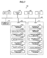
Incidentally, various kinds of processes described in the first and second embodiments may be realized in a manner that a computer executes a program prepared beforehand. Therefore, hereinbelow, an example of the computer which executes the program having the same functions as in the first embodiment and the second embodiment will be described.FIG. 7 is an explanatory diagram illustrating a computer which executes an input control program.
Acomputer 100 which executes the input control program illustrated inFIG. 7 includes an HDD (Hard Disk Drive) 110, aRAM 120, a ROM 130, and a CPU 140. In addition, thecomputer 100 includes aninput unit 150, adisplay unit 160, and a communications unit 170. Moreover, in thecomputer 100, the HDD 110, theRAM 120, the ROM 130, the CPU 140, theinput unit 150, thedisplay unit 160, and the communications unit 170 are connected to each other ova abus 180.
Furthermore, an input control program which enables the same function as in the first and second embodiments to be performed is stored in the HDD 110 beforehand. In addition, a communications program may be recorded in the ROM 130 or a computer-readable recording medium which is readable in a drive (not illustrated) instead of being recorded in the HDD 110. The recording medium may use, for example, a portable recording medium such as a CD-ROM, a DVD disk, and a USB memory, or use a semiconductor memory such as a flash memory. As illustrated inFIG. 7 , the input control program includes anacquisition program 110A, adetection program 110B,display control program 110C, a setting program 110D, acalculation program 110E, asearch program 110F, and aspecification program 110G. Theprograms
The CPU 140 reads theseprograms FIG. 7 , the CPU 140 reads each of theprograms acquisition process 140A, adetection process 140B, adisplay control process 140C, asetting process 140D, acalculation process 140E, asearch process 140F, and aspecification process 140G. The contents of control of each process carried out during the input control is stored in theRAM 120. - [3] In addition, various kinds of processes described in the first and second embodiments may be realized in a manner that a mobile terminal executes software prepared beforehand.
FIG. 8 is a diagram illustrating an example of a software configuration. As illustrated inFIG. 8 , a software element especially related to the input control process is an "input" element for a kernel, a "drawing" element for a library, and a "service" element for an application framework. - According to the embodiments of the disclosure, operability of equipment can be improved and the configuration of equipment can be simplified.
Claims (6)
- An input control device (10, 30) comprising:an acquisition unit (11) that acquires a sensing value that varies depending on a distance between a detection target and an input unit and sensed by a sensing device included in the input unit;a detection unit (12) that detects the detection target based on the acquired sensing value and a threshold selected from among a first threshold corresponding to a first sensing area and a second threshold corresponding to a second sensing area having a shorter distance from the input unit than the first area;a display control unit (14, 33) that enlarges an image displayed on a display unit when the first threshold is set and the detection target is detected; anda setting unit (13) that sets the second threshold instead of the first threshold when the first threshold is set and the detection target is detected.
- The input control device (30) according to claim 1, further comprising:a calculation unit (31) that calculates a contact-predetermined position of the detection target in the input unit, based on the acquired sensing value at detection timing determined based on the first threshold; anda search unit (32) that searches for the detection target in a search range including a position in the display unit corresponding to the contact-predetermined position,wherein the display control unit (33) enlarges the searched selection object.
- The input control device (30) according to claim 2, wherein the calculation unit (31) calculates a contact position of the detection target in the input unit, based on the acquired sensing value at detection timing determined based on the second threshold, and the input control device (30) further comprises a specification unit (34) that specifies the searched selection object as an execution target when a position in the display unit corresponding to the contact position agrees with a display position of the searched selection object.
- The input control device according to any one of claims 1 to 3,
wherein the input unit and the display unit are a touch panel. - An input control program that causes a processor to execute an input control process of:acquiring a sensing value that varies depending on a distance between a detection target and an input unit and sensed by a sensing device included in the input unit;detecting the detection target based on the acquired sensing value and a threshold selected from among a first threshold corresponding to a first sensing area and a second threshold corresponding to a second sensing area having a shorter distance from the input unit than the first area;enlarging an image displayed on a display unit when the first threshold is set and the detection target is detected; andsetting the second threshold instead of the first threshold when the first threshold is set and the detection target is detected.
- An input control method comprising:acquiring a sensing value that varies depending on a distance between a detection target and an input unit and sensed by a sensing device included in the input unit;detecting the detection target based on the acquired sensing value and a threshold selected from among a first threshold corresponding to a first sensing area and a second threshold corresponding to a second sensing area having a shorter distance from the input unit than the first area;enlarging an image displayed on a display unit when the first threshold is set and the detection target is detected; andsetting the second threshold instead of the first threshold when the first threshold is set and the detection target is detected.
Applications Claiming Priority (1)
| Application Number | Priority Date | Filing Date | Title |
|---|---|---|---|
| JP2012061189A JP5949010B2 (en) | 2012-03-16 | 2012-03-16 | INPUT CONTROL DEVICE, INPUT CONTROL PROGRAM, AND INPUT CONTROL METHOD |
Publications (2)
| Publication Number | Publication Date |
|---|---|
| EP2639686A2 true EP2639686A2 (en) | 2013-09-18 |
| EP2639686A3 EP2639686A3 (en) | 2017-07-12 |
Family
ID=47563050
Family Applications (1)
| Application Number | Title | Priority Date | Filing Date |
|---|---|---|---|
| EP12197752.4A Withdrawn EP2639686A3 (en) | 2012-03-16 | 2012-12-18 | Input control device, input control program, and input control method |
Country Status (4)
| Country | Link |
|---|---|
| US (1) | US20130241848A1 (en) |
| EP (1) | EP2639686A3 (en) |
| JP (1) | JP5949010B2 (en) |
| CN (1) | CN103309496A (en) |
Families Citing this family (5)
| Publication number | Priority date | Publication date | Assignee | Title |
|---|---|---|---|---|
| SE463188B (en) | 1988-05-10 | 1990-10-22 | Stormby Nils | BRUSH FOR MEDICAL SAMPLING |
| US9460779B2 (en) * | 2014-05-14 | 2016-10-04 | Macronix International Co., Ltd. | Memory sensing method using one-time sensing table and associated memory device |
| JP6308528B2 (en) * | 2014-08-06 | 2018-04-11 | アルプス電気株式会社 | Capacitive input device |
| JP5993072B1 (en) | 2015-08-27 | 2016-09-14 | レノボ・シンガポール・プライベート・リミテッド | Electronic device user interface, input processing method, and electronic device |
| CN105917296A (en) * | 2016-04-12 | 2016-08-31 | 深圳信炜科技有限公司 | Electronic device and mobile terminal |
Citations (2)
| Publication number | Priority date | Publication date | Assignee | Title |
|---|---|---|---|---|
| JP2009003867A (en) | 2007-06-25 | 2009-01-08 | Panasonic Electric Works Co Ltd | Display device and computer program |
| JP2011022961A (en) | 2009-07-21 | 2011-02-03 | Panasonic Corp | Input control device |
Family Cites Families (13)
| Publication number | Priority date | Publication date | Assignee | Title |
|---|---|---|---|---|
| JPH10269022A (en) * | 1997-03-25 | 1998-10-09 | Hitachi Ltd | Portable information processing device with communication function |
| JP2000322169A (en) * | 1999-04-30 | 2000-11-24 | Internatl Business Mach Corp <Ibm> | Hot spot selection method in graphical user interface |
| CN101354618A (en) * | 2007-07-24 | 2009-01-28 | 英华达(上海)电子有限公司 | Method and apparatus for positioning touch screen |
| US8432365B2 (en) * | 2007-08-30 | 2013-04-30 | Lg Electronics Inc. | Apparatus and method for providing feedback for three-dimensional touchscreen |
| JP2009116769A (en) * | 2007-11-09 | 2009-05-28 | Sony Corp | INPUT DEVICE, INPUT DEVICE CONTROL METHOD, AND PROGRAM |
| CN101533320B (en) * | 2008-03-10 | 2012-04-25 | 神基科技股份有限公司 | Proximity magnification display method and device for area image of touch display device |
| CN102239470B (en) * | 2008-12-04 | 2018-03-16 | 三菱电机株式会社 | Display input device and guider |
| JP4683126B2 (en) * | 2008-12-26 | 2011-05-11 | ブラザー工業株式会社 | Input device |
| US9405456B2 (en) * | 2009-06-08 | 2016-08-02 | Xerox Corporation | Manipulation of displayed objects by virtual magnetism |
| JP5492627B2 (en) * | 2010-03-25 | 2014-05-14 | 株式会社ジャパンディスプレイ | Information display device and information display method |
| JP2012173997A (en) * | 2011-02-22 | 2012-09-10 | Aisin Aw Co Ltd | Display device, display method and display program |
| CN102253749A (en) * | 2011-07-18 | 2011-11-23 | 华为终端有限公司 | Touch screen and input control method thereof |
| TWI469025B (en) * | 2011-08-25 | 2015-01-11 | Touch panel and its dynamic drive control method |
-
2012
- 2012-03-16 JP JP2012061189A patent/JP5949010B2/en active Active
- 2012-12-14 US US13/714,567 patent/US20130241848A1/en not_active Abandoned
- 2012-12-18 EP EP12197752.4A patent/EP2639686A3/en not_active Withdrawn
- 2012-12-31 CN CN2012105930421A patent/CN103309496A/en active Pending
Patent Citations (2)
| Publication number | Priority date | Publication date | Assignee | Title |
|---|---|---|---|---|
| JP2009003867A (en) | 2007-06-25 | 2009-01-08 | Panasonic Electric Works Co Ltd | Display device and computer program |
| JP2011022961A (en) | 2009-07-21 | 2011-02-03 | Panasonic Corp | Input control device |
Also Published As
| Publication number | Publication date |
|---|---|
| JP5949010B2 (en) | 2016-07-06 |
| US20130241848A1 (en) | 2013-09-19 |
| JP2013196203A (en) | 2013-09-30 |
| CN103309496A (en) | 2013-09-18 |
| EP2639686A3 (en) | 2017-07-12 |
Similar Documents
| Publication | Publication Date | Title |
|---|---|---|
| US9329714B2 (en) | Input device, input assistance method, and program | |
| US9250790B2 (en) | Information processing device, method of processing information, and computer program storage device | |
| JP5157969B2 (en) | Information processing apparatus, threshold setting method and program thereof | |
| CN102981747B (en) | Information processor, information processing method and computer program | |
| US10073493B2 (en) | Device and method for controlling a display panel | |
| CN103135930A (en) | Touch screen control method and device | |
| CN107203313B (en) | Method for adjusting desktop display object, mobile terminal and computer readable storage medium | |
| JP2013222283A (en) | Electronic device, and method and program for controlling the same | |
| EP2639686A2 (en) | Input control device, input control program, and input control method | |
| CN106484228B (en) | Double screen switches display methods and mobile terminal | |
| US11353992B2 (en) | Method and device for processing user input on basis of time during which user input is maintained | |
| US9846529B2 (en) | Method for processing information and electronic device | |
| CN104777976A (en) | Interface operation method | |
| KR20130097331A (en) | Apparatus and method for selecting object in device with touch screen | |
| CN107071264A (en) | A kind of image resolution ratio method of adjustment and mobile terminal | |
| KR20130082352A (en) | Apparatus and method for zooming touch screen in electronic device | |
| CN107992262A (en) | Split screen display available interface control method, mobile terminal and computer-readable recording medium | |
| EP2811378A1 (en) | Apparatus and Method for Controlling an Interface Based on Bending | |
| JP5760886B2 (en) | Image display device, image display method, and image display program | |
| CN109032487A (en) | Electronic device control method, electronic device control device, storage medium and electronic device | |
| KR20200050582A (en) | Apparatus and method for determining compensation of touch data based on operation mode of display | |
| WO2015156217A1 (en) | Mobile terminal device | |
| CN105677149B (en) | Electronic device and display processing method | |
| EP2871559A1 (en) | Image display device, image enlargement method, and image enlargement program | |
| US20170285798A1 (en) | Method and system for realizing functional key on side surface |
Legal Events
| Date | Code | Title | Description |
|---|---|---|---|
| PUAI | Public reference made under article 153(3) epc to a published international application that has entered the european phase |
Free format text: ORIGINAL CODE: 0009012 |
|
| AK | Designated contracting states |
Kind code of ref document: A2 Designated state(s): AL AT BE BG CH CY CZ DE DK EE ES FI FR GB GR HR HU IE IS IT LI LT LU LV MC MK MT NL NO PL PT RO RS SE SI SK SM TR |
|
| AX | Request for extension of the european patent |
Extension state: BA ME |
|
| PUAL | Search report despatched |
Free format text: ORIGINAL CODE: 0009013 |
|
| AK | Designated contracting states |
Kind code of ref document: A3 Designated state(s): AL AT BE BG CH CY CZ DE DK EE ES FI FR GB GR HR HU IE IS IT LI LT LU LV MC MK MT NL NO PL PT RO RS SE SI SK SM TR |
|
| AX | Request for extension of the european patent |
Extension state: BA ME |
|
| RIC1 | Information provided on ipc code assigned before grant |
Ipc: G06F 3/0488 20130101AFI20170607BHEP |
|
| STAA | Information on the status of an ep patent application or granted ep patent |
Free format text: STATUS: THE APPLICATION IS DEEMED TO BE WITHDRAWN |
|
| 18D | Application deemed to be withdrawn |
Effective date: 20180113 |