EP2639601A2 - Lenktauchbarer Schwimmer für seismische Quellen und zugehörige Verfahren - Google Patents
Lenktauchbarer Schwimmer für seismische Quellen und zugehörige Verfahren Download PDFInfo
- Publication number
- EP2639601A2 EP2639601A2 EP13159289.1A EP13159289A EP2639601A2 EP 2639601 A2 EP2639601 A2 EP 2639601A2 EP 13159289 A EP13159289 A EP 13159289A EP 2639601 A2 EP2639601 A2 EP 2639601A2
- Authority
- EP
- European Patent Office
- Prior art keywords
- submersible float
- float
- submersible
- depth
- seismic source
- Prior art date
- Legal status (The legal status is an assumption and is not a legal conclusion. Google has not performed a legal analysis and makes no representation as to the accuracy of the status listed.)
- Withdrawn
Links
Images




Classifications
-
- G—PHYSICS
- G01—MEASURING; TESTING
- G01V—GEOPHYSICS; GRAVITATIONAL MEASUREMENTS; DETECTING MASSES OR OBJECTS; TAGS
- G01V1/00—Seismology; Seismic or acoustic prospecting or detecting
- G01V1/38—Seismology; Seismic or acoustic prospecting or detecting specially adapted for water-covered areas
- G01V1/3817—Positioning of seismic devices
-
- B—PERFORMING OPERATIONS; TRANSPORTING
- B63—SHIPS OR OTHER WATERBORNE VESSELS; RELATED EQUIPMENT
- B63B—SHIPS OR OTHER WATERBORNE VESSELS; EQUIPMENT FOR SHIPPING
- B63B21/00—Tying-up; Shifting, towing, or pushing equipment; Anchoring
- B63B21/56—Towing or pushing equipment
- B63B21/66—Equipment specially adapted for towing underwater objects or vessels, e.g. fairings for tow-cables
-
- B—PERFORMING OPERATIONS; TRANSPORTING
- B63—SHIPS OR OTHER WATERBORNE VESSELS; RELATED EQUIPMENT
- B63B—SHIPS OR OTHER WATERBORNE VESSELS; EQUIPMENT FOR SHIPPING
- B63B22/00—Buoys
- B63B22/18—Buoys having means to control attitude or position, e.g. reaction surfaces or tether
-
- G—PHYSICS
- G01—MEASURING; TESTING
- G01V—GEOPHYSICS; GRAVITATIONAL MEASUREMENTS; DETECTING MASSES OR OBJECTS; TAGS
- G01V2210/00—Details of seismic processing or analysis
- G01V2210/10—Aspects of acoustic signal generation or detection
- G01V2210/12—Signal generation
- G01V2210/129—Source location
- G01V2210/1293—Sea
Definitions
- Embodiments of the subject matter disclosed herein generally relate to seismic sources having a steerable submersible float configured to control positions of individual seismic sources attached to the steerable submersible float and related methods.
- Marine explorations investigate and map the structure and character of geological formations under a body of water using reflection seismology.
- Reflection seismology is a method of geophysical exploration to determine the properties of earth's subsurface, which are especially helpful in the oil and gas industry.
- Marine reflection seismology is based on using a controlled source of energy that sends the energy into the earth. The depth and horizontal location of features causing reflections are evaluated by measuring the time it takes for the reflections to arrive at plural receivers. These features may be associated with subterranean hydrocarbon reservoirs.
- a traditional marine exploration system is illustrated in Figure 1 .
- a vessel 100 tows a seismic source 102 and an array of seismic receivers 104 provided on streamers 106.
- the streamers may be disposed horizontally, i.e., lying at a constant depth relative to a surface 108 of the water.
- the streamers may be disposed to have other than horizontal spatial arrangements.
- the seismic source 102 is configured to generate a seismic wave 110, that propagates downward toward the seafloor 120 and penetrates the formations under the seafloor until eventually it is reflected at discontinuity locations 122.
- the reflected seismic wave 130 propagates upward until it is detected by one of the receivers 104 on the streamer 106.
- Based on the data collected by the receivers an image of the subsurface formation is generated by further analyses of the collected data.
- a seismic source array typically includes plural individual source elements grouped in one or more sub-arrays.
- the individual source elements may be distributed in various patterns, e.g., circular, linear, at various depths in the water. Maintaining relative horizontal positions and depths of the seismic sources and the streamers according to a desired geometry is desirable in order to ensure accuracy and resolution of the extracted information.
- achieving this type of control has proven challenging due to marine currents and other disturbances, including, for example, the trailing air bubbles that occur when compressed air guns are discharged.
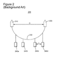
- Figure 2 illustrates a marine exploration system 200 in which two vessels 210 and 220 sail on correlated trajectories at a distance D from one another, while pulling a rope or cable 230 to which plural arrays of individual sources 240a, 240b, 240c and 240d are attached to be towed at a distance C from one another.
- a rope or cable 230 to which plural arrays of individual sources 240a, 240b, 240c and 240d are attached to be towed at a distance C from one another.
- This mechanism also has an undesirably slow reaction time.
- the conventional sources and means of controlling position and depth thereof have a slow reaction time and limited maneuverability.
- Seismic sources include a steerable submersible float configured to control their position in a plane perpendicular to the towing direction by adjusting angles of one or more rotatable surfaces. These seismic sources provide the advantages of an enhanced flexibility and stability in their position during a marine exploration.
- the presence of the steerable submersible float enables arctic exploration, 4-dimensional (4D) time lapse acquisition and allows continuing marine exploration during a broader range of weather conditions.
- Source steering in a 4D time lapse acquisition refers to steering a source array to follow a source route from a previous acquisition conducted months or years ago in the same area. The source route can be irregular because of currents or other interference.
- a seismic source configured to be towed underwater includes a submersible float and a plurality of individual sources.
- the submersible float is configured to control at least one of a depth and a horizontal position of the submersible float by adjusting angles of one or more rotatable surfaces attached to the submersible float.
- the horizontal position is defined to be along a horizontal direction that is substantially perpendicular to a towing direction and to gravity.
- the individual sources hang under the submersible float and are configured to operate at a depth larger than the depth of the submersible float.
- a method for performing seismic marine exploration includes providing a seismic source including (A) a submersible float, and (B) a plurality of individual sources hanging under the submersible float and configured to operate at a depth larger than a depth of the submersible float.
- the method further includes adjusting angles of one or more rotatable surfaces attached to the submersible float to steer the submersible float towards a target position.
- the submersible float is configured to be towed at a target depth and a target horizontal position.
- the towing mechanism is configured to connect the submersible float to a tow cable such that a longitudinal axis thereof to make an adjustable non-zero angle with a towing direction.
- the individual sources hanging under the submersible float and are attached at different positions along the longitudinal axis of the submersible float.
- the individual sources are configured to operate at a depth larger than the target depth of the submersible float.
- Figure 1 illustrates a marine exploration system
- Figure 2 is a schematic diagram of a seismic source towed by two vessels
- Figure 3 is a side view of a seismic source according to an exemplary embodiment
- Figure 4 is a front view of a submersible float of a seismic source according to an exemplary embodiment
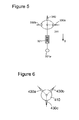
- Figure 5 is a front view of a submersible float of a seismic source according to another exemplary embodiment
- Figure 6 is a front view of a submersible float of a seismic source according to another exemplary embodiment
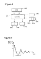
- Figure 7 is block diagram of a seismic source according to another exemplary embodiment
- Figure 8 is a graph illustrating pressure variation measured by a near field sensor as a function of time after a gun is fired
- Figures 9A and 9B illustrate the manner in which a pressure oscillation caused by an individual source firing affects stability of a float towed underwater with its longitudinal axis substantially parallel to the towing direction, according to an exemplary embodiment
- Figures 10A and 10B illustrate the manner in which a pressure oscillation caused by an individual source firing affects stability of a float towed underwater with its longitudinal axis making a non-zero angle with the towing direction, according to an exemplary embodiment
- Figure 11 is a submersible float of a seismic source according to another exemplary embodiment
- Figure 12 illustrates the manner of attaching a towing cable to a float according to another exemplary embodiment
- Figure 13 is a seismic source with plural floats according to another exemplary embodiment.
- Figure 14 is a flowchart of a method for performing marine exploration according to an exemplary embodiment.
- FIG 3 illustrates a seismic source 300 to be towed by a vessel 100 according to an exemplary embodiment.
- the term “seismic source” refers to a device configured to generate a seismic wave.
- plural such sources may be grouped behind a vessel and the “seismic source” may include plural groups.
- the seismic source 300 includes a submersible float 310 and plural individual sources 320a, 320b, 320c (the number of individual sources is not intended to be limited to three).
- the submersible float 310 is configured to operate at depths at which it is no longer affected by water surface effects and weather, for example, up to 15-20 m below the water surface.
- the individual sources 320a, 320b, 320c are attached under the submersible float 310 at different positions along a longitudinal axis 301 (in the towing direction T) of the submersible float 310.
- the individual sources may be air guns.
- the submersible float 310 is connected to the vessel 100 via a towing cable 315.
- Figure 3 illustrates a side view of the submersible float and
- Figure 4 is a front view thereof, i.e., the longitudinal axis is as coming out of the page.
- a horizontal direction 302 is substantially perpendicular to the longitudinal direction 301 and a vertical direction 303 that is parallel to gravity g.
- the individual sources are heavy (e.g., hundreds of kilograms) so they tend to lie along the vertical direction 303.
- the individual sources 320a, 320b and 320c may be configured to hang at an adjustable distance d (e.g., to 5-6 m) under the submersible float 310. In one embodiment, the individual sources may be withdrawn inside or near the submersible float to facilitate retrieval of the seismic source.
- d e.g., to 5-6 m
- an oscillation damping mechanism 321 may be located between the submersible float 311 and the individual source 321a (other individual sources may not be visible being hidden behind the source 321a in this view).
- the damping mechanism 321 may include a spring.
- Other damping mechanisms may be used as it would be recognized by those skilled in the art.
- Rotatable wings which are labeled 330a and 330b in Figures 3, 4 and 5 , are located laterally on the submersible float 310 and 311, respectively, and are configured to rotate in order to adjust their angles with a horizontal plane, thereby to control the depth of the submersible float.
- the horizontal plane may be, for example, defined as including the longitudinal axis 301 and the horizontal direction 302 (that is, substantially perpendicular to the towing direction T). However, in a more general sense, the horizontal plane can be defined as being perpendicular to the gravity direction.
- the submersible float 310 or 311 may also have a tail rudder 340 configured to have its angle with a vertical plane adjusted to control the horizontal position of the submersible float.
- the vertical plane may be, for example, defined as including the longitudinal axis 301 and the vertical axis 303. However, in a more general sense, the vertical plane can be defined as being perpendicular to the horizontal direction 302.
- the tail rudder 340 is illustrated in Figure 3 as being located at the back end of the submersible float 310, this position is exemplary and it is not intended to be limiting.
- the wings 330a and 330b and the rudder 340 may be mounted at various locations on the submersible float: front, middle, tail, upper surface or lower surface thereof.
- three fins 430a, 430b and 430c may be arranged as illustrated in Figure 6 .
- Fins 430a and 430b may be rotated at different angles to generate forces having horizontal and/or vertical components in order to steer the float 410 towards a target position.
- Fin 430c may be ballasted and configured to rotate freely in order to stabilize the float 410.
- the submersible float 310 may also include one or more ballast chambers 350 configured to be filled with or emptied of water, thereby enabling adjustment of the depth of the submersible float 310.
- the seismic source 300 may also include one or more position sensors configured to determine a current location of the submersible float.
- the current location may be determined using a Global Positioning System (GPS) device 360 floating on the water surface while being attached to the submersible float 310.
- GPS Global Positioning System
- the GPS device 360 may be retractable to adjust to changes in the depth of the submersible float 310.
- the position sensors may be underwater acoustic positioning sensors determining the submersible float's position relative to a reference position, such as, the towing vessel.
- the submersible float may be configured to be controlled by a control unit 370.
- the control unit 370 is configured to receive information about the current location of the submersible float from the position sensors, such as the GPS device 360, and to send control signals to the rotatable surfaces, such as the pair of wings 330a and 330b, and the tail rudder 340, to steer the submersible float 310 toward a target position.
- the control unit 370 may be located inside the float 310 or on the towing vessel 100.
- the control unit 370 may also be configured to control the adjustable distance d under the submersible float 310 at which the individual sources are positioned. Alternatively or additionally, the control unit 370 may also be configured to control filing or emptying the one or more ballast chambers 350.
- Figure 8 represents pressure variation measured by a near field sensor and caused by two 250 cm 3 parallel guns positioned at 5 m depth, firing air at 3000 psi.
- the first (largest) pressure oscillation corresponds to a bubble spreading, in a first approximation, like a spherically wave in the water.
- the second and following pressure oscillations reach the float at larger distances from the source than the first pressure oscillation and no longer have enough energy to cause a significant de-stabilizing effect.
- Figures 9A and 9B are an aerial view and a vertical view of a float 510 having the individual sources (not shown) arranged along its longitudinal axis (i.e., the same source arrangement as illustrated in Figure 3 ), the float 510 being towed with its longitudinal axis parallel to the towing direction T.
- the bubbles 535 i.e., pressure oscillations
- the float 510 as positioned at t 1 is drawn using a continuous line
- the float 510 as positioned at t 2 is drawn using a dashed line.
- the float 510 advances a distance equal to the towing speed v (e.g., about 5 knots or 2.5 m/s) times the time interval t 2 - t 1 .
- This distance v(t 2 - t 1 ) traveled by the float 510 is likely less than the length of the float.
- a float 511 is configured to be towed such that its longitudinal axis to make a non-zero angle ⁇ with the towing direction T.
- Figures 10A and 10B are an aerial view and a front view of the float 511 having the individual sources arranged along its longitudinal axis (i.e., the same source arrangement as illustrated in Figure 3 ).
- the energy per unit area of an expanding spherical wave decreases as 1/r 2 (where r is the distance from the point source).
- E 0 is the energy per unit area when the pressure oscillation reaches the float 510 towed with the sources aligned along the towing direction (i.e., as in Figure 9A )
- FIG 11 is an aerial view of a seismic source 600 configured to be towed underwater via a towing cable 615 according to another exemplary embodiment.
- the seismic source 600 includes a submersible float 610 and plural individual sources (not shown) attached under the submersible float 610, at different positions along a longitudinal axis 601 of the submersible float 610. Similar to source 300, the seismic source 600 includes wings 630a and 630b and a tail rudder 640.
- the towing cable 615 is attached on a side of the submersible float 610 at 655, such that the towing cable 615 makes a non-zero angle with the longitudinal axis 601.
- the manner in which the towing cable 615 is attached on the side of the submersible float 610 may allow varying the non-zero angle, thus providing an additional degree of liberty in maneuvering the seismic source.
- the towing cable 615 is attached to the submersible float 610 via two tow ropes 656 and 657.
- the rope 656 can be attached to a fixed position on the submersible float 610, but the position at which the rope 657 is attached to the submersible float 610 may vary longitudinally, thereby varying the angle ⁇ of the float 610 with the towing direction T. This angle adjustment can make the float operate as a diverter to steer itself to the specified position together with other steering means.
- the float 610 may receive air for the ballast chambers and/or electrical/optical signals via a separate link 658.
- FIG 13 illustrates another embodiment of a seismic source 660 having two floats 670 and 675 pulled by the same cable 680.
- Each of the floats has attached a cluster of seismic guns (i.e., individual sources) 690 and 695.
- support bars 692 and 697 are attached to the floats 670 and 675, respectively.
- the individual sources 694 and 699 are arranged along the support bars 692 and 697, respectively.
- the clusters may have multiple levels, multiple rows, multiple columns or may have the guns arranged circularly.
- each cluster of guns trails behind the float from which it is attached, and the spacing between floats may be calculated such that to minimize the effect of the pressure variation due to the guns 690 attached to the first float 670, on the stability of the second float 675 towed behind the first float 670.
- the number of floats towed in series is not limited to two. This embodiment also has the advantage that the source segments such as a float and the attached cluster of sources may be easily replaced for a more efficient handling and troubleshooting.
- An angle of the support bar 692 or 697 with the towing direction in a horizontal plane may be adjusted, to achieve a similar reduction of the de-stabilizing effect of pressure bubbles as by towing the submersible float with sources attached longitudinally, at a non-zero angle with the towing direction. Being able to adjust this angle also provides more flexibility when the seismic source is recovered.
- a vessel often tows two or more survey seismic source arrays.
- An array may include multiple source floats spread horizontally to maintain a distance of about 10 m between adjacent floats within the same array, while the arrays may have a distance of about 50 m in-between.
- the non-zero angle of the guns with the towing direction may be pre-set (fixed) or may be tuned for each float.
- Some of the above-described embodiments provide an enhanced ability to maneuver a seismic source towed underwater including (1) vertical steering with wings, (2) horizontal steering with the tail rudder, (3) depth adjustment by filling or emptying ballast chambers, and (4) angular positioning of the longitudinal axis by attaching the towing cable on a side of the submersible float.
- a seismic source is suitable for use in arctic exploration, since the submerged float would not be affected by floating ice.
- this seismic source has enhanced capability to operate in rough weather. Further, this seismic source allows source steering that is required for 4D time lapse marine acquisition.
- a flow diagram of a method 700 for performing marine exploration is illustrated in Figure 14 .
- the method 700 includes providing a seismic source, including (A) a submersible float, and (B) a plurality of individual sources hanging under the submersible float and configured to operate at a depth larger than a depth of the submersible float, at S710.
- the method 700 further includes adjusting angles of one or more rotatable surfaces attached to the submersible float to steer the submersible float toward a target position at S720.
- the target position may be characterized by depth and a horizontal position in a plane perpendicular to the towing direction.
- the horizontal position may be defined along a direction substantially perpendicular to the towing direction and to gravity.
- the method 700 may also include extracting information about a formation under a seabed based on reflections of seismic waves generated by the individual sources.
- the step of adjusting angles may include (1) adjusting an angle of a pair of rotatable wings located laterally on the submersible float to steer the submersible float vertically, and/or (2) adjusting an angle of a tail rudder with a vertical plane to steer the submersible float horizontally.
- the depth of the submersible float may also be adjusted by filling or emptying ballast chambers with/of fluid.
- the individual sources may be configured to hang at an adjustable distance under the submersible float, and the method 700 may further include adjusting the distance at which the individual sources hang under the submersible float.
- the method 700 further includes determining a current location of the submersible float, and then generating and transmitting control signals to adjust the depth and the horizontal position, based on the current location.
- the current position may be determined using a GPS device floating above and attached to the submersible float.
- the towing cable may be attached to a side of the submersible float to make a non-zero angle with the longitudinal axis of the submersible float, and the method may then further include adjusting a location where the towing cable is attached to the side of the submersible float.
- the disclosed exemplary embodiments provide a seismic source with a steerable submersible float and related methods. It should be understood that this description is not intended to limit the invention. On the contrary, the exemplary embodiments are intended to cover alternatives, modifications and equivalents, which are included in the spirit and scope of the invention as defined by the appended claims. Further, in the detailed description of the exemplary embodiments, numerous specific details are set forth in order to provide a comprehensive understanding of the claimed invention. However, one skilled in the art would understand that various embodiments may be practiced without such specific details.
Landscapes
- Life Sciences & Earth Sciences (AREA)
- Engineering & Computer Science (AREA)
- Chemical & Material Sciences (AREA)
- Physics & Mathematics (AREA)
- Combustion & Propulsion (AREA)
- Mechanical Engineering (AREA)
- Ocean & Marine Engineering (AREA)
- Acoustics & Sound (AREA)
- Oceanography (AREA)
- Environmental & Geological Engineering (AREA)
- Geology (AREA)
- Remote Sensing (AREA)
- General Life Sciences & Earth Sciences (AREA)
- General Physics & Mathematics (AREA)
- Geophysics (AREA)
- Chemical Kinetics & Catalysis (AREA)
- Geophysics And Detection Of Objects (AREA)
Applications Claiming Priority (1)
| Application Number | Priority Date | Filing Date | Title |
|---|---|---|---|
| US13/422,474 US9341730B2 (en) | 2012-03-16 | 2012-03-16 | Steering submersible float for seismic sources and related methods |
Publications (1)
| Publication Number | Publication Date |
|---|---|
| EP2639601A2 true EP2639601A2 (de) | 2013-09-18 |
Family
ID=47915450
Family Applications (1)
| Application Number | Title | Priority Date | Filing Date |
|---|---|---|---|
| EP13159289.1A Withdrawn EP2639601A2 (de) | 2012-03-16 | 2013-03-14 | Lenktauchbarer Schwimmer für seismische Quellen und zugehörige Verfahren |
Country Status (3)
| Country | Link |
|---|---|
| US (1) | US9341730B2 (de) |
| EP (1) | EP2639601A2 (de) |
| AU (1) | AU2013201350B2 (de) |
Cited By (3)
| Publication number | Priority date | Publication date | Assignee | Title |
|---|---|---|---|---|
| GB2513468A (en) * | 2013-03-13 | 2014-10-29 | Pgs Geophysical As | Wing for wide tow of geophysical survey sources |
| US9921327B2 (en) | 2015-03-25 | 2018-03-20 | Cgg Services Sas | Submerged front end buoy |
| US10042066B2 (en) | 2015-03-25 | 2018-08-07 | Cgg Services Sas | Method and device for passively and automatically winding seismic survey equipment cable |
Families Citing this family (8)
| Publication number | Priority date | Publication date | Assignee | Title |
|---|---|---|---|---|
| FR2964201B1 (fr) * | 2010-08-30 | 2013-08-16 | Cggveritas Services Sa | Dispositif d'emission d'ondes sismiques pour l'acquisition sismique marine et procede pour sa mise en oeuvre |
| MX364105B (es) * | 2014-03-14 | 2019-04-12 | Cgg Services Sa | Método y dispositivo para controlar una disposición de subarreglo de fuente. |
| NO338727B1 (no) * | 2014-05-15 | 2016-10-10 | Polarcus Dncc | Innhenting av seismiske data i områder dekket av is |
| US10703445B2 (en) * | 2017-02-24 | 2020-07-07 | Pgs Geophysical As | System for source towing at depth |
| KR101803430B1 (ko) | 2017-07-07 | 2017-11-30 | 네이버시스템(주) | 해수에 의한 퇴적과 침식에 의한 해저면의 굴곡변화와 지형변화를 확인해 위치정보를 갱신하는 지형확인시스템 |
| EP3657127B1 (de) * | 2018-11-21 | 2022-08-03 | Sercel | Verfahren zur planung einer trajektorie in gegenwart von wasserstrom |
| CN112540402B (zh) * | 2020-12-07 | 2025-07-01 | 福建省地震局 | 两栖气枪震源的自动收放系统 |
| CN116359978B (zh) * | 2022-12-07 | 2025-09-26 | 中国电建集团贵阳勘测设计研究院有限公司 | 一种单台站震源快速精确定位方法及装置 |
Family Cites Families (51)
| Publication number | Priority date | Publication date | Assignee | Title |
|---|---|---|---|---|
| US2729910A (en) | 1950-04-26 | 1956-01-10 | Raytheon Mfg Co | Controllable depth maintaining devices |
| US2771961A (en) * | 1955-07-27 | 1956-11-27 | California Research Corp | Method of initiating underwater seismic disturbances |
| US3019412A (en) * | 1959-05-29 | 1962-01-30 | Continental Oil Co | Floating support for seismic transducers |
| US3160133A (en) | 1961-12-28 | 1964-12-08 | Harold H Walker | Submarine vehicle |
| US3375800A (en) | 1967-04-07 | 1968-04-02 | Jimmy R. Cole | Seismic cable depth control apparatus |
| US3541989A (en) | 1968-03-04 | 1970-11-24 | Willie Burt Leonard | Hydropneumatic measurement and control from buoyed bodies |
| US3757723A (en) | 1971-04-07 | 1973-09-11 | Mc Mullen J Associates Inc | Fixed-angle stabilizing fin system |
| FR2397974A1 (fr) * | 1977-07-18 | 1979-02-16 | Inst Francais Du Petrole | Dispositif immerge porteur d'appareils oceanographique, a controle automatique de profondeur |
| US4463701A (en) * | 1980-02-28 | 1984-08-07 | The United States Of America As Represented By The Secretary Of The Navy | Paravane with automatic depth control |
| US4549499A (en) * | 1981-05-19 | 1985-10-29 | Mobil Oil Corporation | Floatation apparatus for marine seismic exploration |
| US4648322A (en) | 1985-07-02 | 1987-03-10 | Sundstrand Corporation | Propulsion and directional control mechanism for an underwater device |
| US4721180A (en) * | 1986-11-26 | 1988-01-26 | Western Atlas International, Inc. | Marine seismic source array |
| US4726315A (en) * | 1987-04-16 | 1988-02-23 | Teledyne Exploration | Apparatus for towing arrays of geophysical devices |
| NO173206C (no) * | 1988-06-06 | 1999-11-11 | Geco As | Fremgangsmåte til posisjonsbestemmelse av minst to seismiske kabler i et refleksjonsseismisk målesystem |
| US4974213A (en) * | 1988-12-16 | 1990-11-27 | Siwecki Thomas L | Passive active underwater sound detection apparatus |
| NO170866C (no) * | 1990-07-12 | 1992-12-16 | Geco As | Fremgangsmaate og anordning til stabilisering av seismiskeenergikilder |
| NO172872B (no) * | 1990-10-17 | 1993-06-07 | Geco As | Anordning ved seismiske energikilder |
| NO301950B1 (no) * | 1993-02-23 | 1997-12-29 | Geco As | Anordning til styring av seismisk utstyr som blir slept av et seismisk fartöy under vannoverflaten og fremgangsmåte for posisjonering av slikt utstyr |
| US5402745A (en) | 1994-05-02 | 1995-04-04 | The United States Of America As Represented By The Secretary Of The Navy | In-line rotational positioning module for towed array paravanes |
| NO301445B1 (no) * | 1994-07-13 | 1997-10-27 | Petroleum Geo Services As | Anordning for sleping |
| GB9424744D0 (en) * | 1994-12-08 | 1995-02-08 | Geco As | Method of and apparatus for marine seismic surveying |
| US6498768B1 (en) * | 1997-09-02 | 2002-12-24 | Schlumberger Technology Corporation | Method and apparatus for marine seismic surveying including multiples streamers from a lead-in |
| US6011752A (en) | 1998-08-03 | 2000-01-04 | Western Atlas International, Inc. | Seismic streamer position control module |
| US6002648A (en) * | 1998-10-16 | 1999-12-14 | Western Atlas International, Inc. | Slotted cylinder marine siesmic method and source |
| FR2796360B1 (fr) * | 1999-07-16 | 2001-09-07 | Geco As | Flotteur de ligne touee |
| US6208584B1 (en) * | 1999-09-16 | 2001-03-27 | L-3 Communications Corporation | Place calibration of sonar receive array |
| US6691038B2 (en) * | 2001-06-15 | 2004-02-10 | Westerngeco L.L.C. | Active separation tracking and positioning system for towed seismic arrays |
| US20040000446A1 (en) * | 2002-07-01 | 2004-01-01 | Barber Harold P. | Seismic signaling apparatus and method for enhancing signal repeatability |
| GB2400662B (en) * | 2003-04-15 | 2006-08-09 | Westerngeco Seismic Holdings | Active steering for marine seismic sources |
| US7415936B2 (en) | 2004-06-03 | 2008-08-26 | Westerngeco L.L.C. | Active steering for marine sources |
| US8824239B2 (en) * | 2004-03-17 | 2014-09-02 | Westerngeco L.L.C. | Marine seismic survey method and system |
| US7800977B2 (en) * | 2004-06-01 | 2010-09-21 | Westerngeco L.L.C. | Pre-stack combining of over/under seismic data |
| US20060176774A1 (en) | 2005-02-10 | 2006-08-10 | Rune Toennessen | Apparatus and methods for controlling position of marine seismic sources |
| US7518951B2 (en) * | 2005-03-22 | 2009-04-14 | Westerngeco L.L.C. | Systems and methods for seismic streamer positioning |
| US7450467B2 (en) * | 2005-04-08 | 2008-11-11 | Westerngeco L.L.C. | Apparatus and methods for seismic streamer positioning |
| US7577060B2 (en) * | 2005-04-08 | 2009-08-18 | Westerngeco L.L.C. | Systems and methods for steering seismic arrays |
| US7660191B2 (en) * | 2005-07-12 | 2010-02-09 | Westerngeco L.L.C. | Methods and apparatus for acquisition of marine seismic data |
| US8391102B2 (en) * | 2005-08-26 | 2013-03-05 | Westerngeco L.L.C. | Automatic systems and methods for positioning marine seismic equipment |
| GB2433594B (en) * | 2005-12-23 | 2008-08-13 | Westerngeco Seismic Holdings | Methods and systems for determining signatures for arrays of marine seismic sources for seismic analysis |
| US7804738B2 (en) | 2006-03-21 | 2010-09-28 | Westerngeco L.L.C. | Active steering systems and methods for marine seismic sources |
| US7480204B2 (en) * | 2006-07-07 | 2009-01-20 | Westerngeco L.L.C. | Seismic data processing |
| US7457193B2 (en) * | 2006-07-21 | 2008-11-25 | Pgs Geophysical As | Seismic source and source array having depth-control and steering capability |
| FR2912818A1 (fr) * | 2007-02-19 | 2008-08-22 | Georges Grall | Systeme de flutes automotrices pour prospection en sismique marine 3d a grande productivite |
| GB2460865B (en) * | 2008-06-13 | 2010-10-20 | Geco Technology Bv | Position determination of a seismic source array |
| US8593905B2 (en) | 2009-03-09 | 2013-11-26 | Ion Geophysical Corporation | Marine seismic surveying in icy or obstructed waters |
| US8427901B2 (en) * | 2009-12-21 | 2013-04-23 | Pgs Geophysical As | Combined impulsive and non-impulsive seismic sources |
| US8570829B2 (en) * | 2009-12-22 | 2013-10-29 | Pgs Geophysical As | Depth steerable seismic source array |
| US8891331B2 (en) * | 2011-09-21 | 2014-11-18 | Cggveritas Services Sa | Steerable source array and method |
| US8881665B2 (en) * | 2011-09-30 | 2014-11-11 | Cggveritas Services Sa | Deployment and recovery vessel for autonomous underwater vehicle for seismic survey |
| US20130083622A1 (en) * | 2011-09-30 | 2013-04-04 | Cggveritas Services Sa | Underwater node for seismic surveys |
| US20140321238A1 (en) * | 2013-04-25 | 2014-10-30 | Cgg Services Sa | Remotely operated modular positioning vehicle and method |
-
2012
- 2012-03-16 US US13/422,474 patent/US9341730B2/en active Active
-
2013
- 2013-03-05 AU AU2013201350A patent/AU2013201350B2/en not_active Ceased
- 2013-03-14 EP EP13159289.1A patent/EP2639601A2/de not_active Withdrawn
Cited By (6)
| Publication number | Priority date | Publication date | Assignee | Title |
|---|---|---|---|---|
| GB2513468A (en) * | 2013-03-13 | 2014-10-29 | Pgs Geophysical As | Wing for wide tow of geophysical survey sources |
| US9551801B2 (en) | 2013-03-13 | 2017-01-24 | Pgs Geophysical As | Wing for wide tow of geophysical survey sources |
| GB2513468B (en) * | 2013-03-13 | 2017-06-21 | Pgs Geophysical As | Wing for wide tow of geophysical survey sources |
| US10274626B2 (en) | 2013-03-13 | 2019-04-30 | Pgs Geophysical As | Wing for wide tow of geophysical survey sources |
| US9921327B2 (en) | 2015-03-25 | 2018-03-20 | Cgg Services Sas | Submerged front end buoy |
| US10042066B2 (en) | 2015-03-25 | 2018-08-07 | Cgg Services Sas | Method and device for passively and automatically winding seismic survey equipment cable |
Also Published As
| Publication number | Publication date |
|---|---|
| AU2013201350B2 (en) | 2015-07-30 |
| US9341730B2 (en) | 2016-05-17 |
| US20130242694A1 (en) | 2013-09-19 |
| AU2013201350A1 (en) | 2013-10-03 |
Similar Documents
| Publication | Publication Date | Title |
|---|---|---|
| AU2013201350B2 (en) | Steering submersible float for seismic sources and related methods | |
| US9932093B2 (en) | Towing methods and systems for geophysical surveys | |
| US7203130B1 (en) | Methods for deriving shape of seismic data acquisition cables and streamers employing a force model | |
| US8976623B2 (en) | Towing methods and systems for geophysical surveys | |
| US7167412B2 (en) | Apparatus for steering a marine seismic streamer via controlled bending | |
| EP2771722B1 (de) | Lenkbarer verkleidungsstrang | |
| US11325680B2 (en) | Adjustable buoyancy foil | |
| EP3308198B1 (de) | Meeresseismische messungen | |
| US9250345B2 (en) | Reduced-drag towing of geophysical equipment | |
| CN101253420A (zh) | 海洋地震数据采集用的方法和设备 | |
| NO332924B1 (no) | Marint seismisk tauesystem med separate taueanordninger som har evne til uavhengig bevegelse | |
| CA2935388C (en) | Wide source seismic towing configuration | |
| US20180259666A1 (en) | Marine mixed-spread system and method for data acquisition | |
| US10495621B2 (en) | Apparatus and method for surveying | |
| US20060133200A1 (en) | Apparatus for steering a marine seismic streamer via controlled water ejection | |
| US9921327B2 (en) | Submerged front end buoy | |
| GB2513468A (en) | Wing for wide tow of geophysical survey sources | |
| KR101656860B1 (ko) | 분리형 3차원 해양 탄성파 탐사를 위한 베인 각도조절식 디플렉터 시스템 | |
| BR102013006420A2 (pt) | Flutuador submergível dirigível para fontes sísmicas e métodos relacionados | |
| AU2012203912B2 (en) | Towing methods and systems for geophysical surveys |
Legal Events
| Date | Code | Title | Description |
|---|---|---|---|
| PUAI | Public reference made under article 153(3) epc to a published international application that has entered the european phase |
Free format text: ORIGINAL CODE: 0009012 |
|
| AK | Designated contracting states |
Kind code of ref document: A2 Designated state(s): AL AT BE BG CH CY CZ DE DK EE ES FI FR GB GR HR HU IE IS IT LI LT LU LV MC MK MT NL NO PL PT RO RS SE SI SK SM TR |
|
| AX | Request for extension of the european patent |
Extension state: BA ME |
|
| RAP1 | Party data changed (applicant data changed or rights of an application transferred) |
Owner name: CGG SERVICES SA |
|
| STAA | Information on the status of an ep patent application or granted ep patent |
Free format text: STATUS: THE APPLICATION IS DEEMED TO BE WITHDRAWN |
|
| 18D | Application deemed to be withdrawn |
Effective date: 20161001 |