EP2639534A2 - Refrigerator - Google Patents
Refrigerator Download PDFInfo
- Publication number
- EP2639534A2 EP2639534A2 EP13159689.2A EP13159689A EP2639534A2 EP 2639534 A2 EP2639534 A2 EP 2639534A2 EP 13159689 A EP13159689 A EP 13159689A EP 2639534 A2 EP2639534 A2 EP 2639534A2
- Authority
- EP
- European Patent Office
- Prior art keywords
- rotating bar
- door
- refrigerator
- case
- guide
- Prior art date
- Legal status (The legal status is an assumption and is not a legal conclusion. Google has not performed a legal analysis and makes no representation as to the accuracy of the status listed.)
- Granted
Links
- 238000007789 sealing Methods 0.000 claims abstract description 12
- 238000003780 insertion Methods 0.000 claims description 37
- 230000037431 insertion Effects 0.000 claims description 37
- 238000009413 insulation Methods 0.000 claims description 21
- 230000000903 blocking effect Effects 0.000 claims description 8
- 238000010438 heat treatment Methods 0.000 claims description 5
- 238000003825 pressing Methods 0.000 claims description 3
- 238000013459 approach Methods 0.000 claims 1
- 230000008878 coupling Effects 0.000 description 7
- 238000010168 coupling process Methods 0.000 description 7
- 238000005859 coupling reaction Methods 0.000 description 7
- 238000007710 freezing Methods 0.000 description 6
- 230000008014 freezing Effects 0.000 description 6
- 239000000463 material Substances 0.000 description 6
- 238000000034 method Methods 0.000 description 6
- 238000005192 partition Methods 0.000 description 4
- 235000013305 food Nutrition 0.000 description 3
- 239000004794 expanded polystyrene Substances 0.000 description 2
- 239000002184 metal Substances 0.000 description 2
- 230000000149 penetrating effect Effects 0.000 description 2
- 239000004033 plastic Substances 0.000 description 2
- 239000004812 Fluorinated ethylene propylene Substances 0.000 description 1
- 230000002159 abnormal effect Effects 0.000 description 1
- 239000000853 adhesive Substances 0.000 description 1
- 230000001070 adhesive effect Effects 0.000 description 1
- 239000011248 coating agent Substances 0.000 description 1
- 238000000576 coating method Methods 0.000 description 1
- 238000001816 cooling Methods 0.000 description 1
- HQQADJVZYDDRJT-UHFFFAOYSA-N ethene;prop-1-ene Chemical group C=C.CC=C HQQADJVZYDDRJT-UHFFFAOYSA-N 0.000 description 1
- 238000002347 injection Methods 0.000 description 1
- 239000007924 injection Substances 0.000 description 1
- 239000007769 metal material Substances 0.000 description 1
- 239000012811 non-conductive material Substances 0.000 description 1
- 229920009441 perflouroethylene propylene Polymers 0.000 description 1
- 239000003507 refrigerant Substances 0.000 description 1
- 229910052710 silicon Inorganic materials 0.000 description 1
- 239000010703 silicon Substances 0.000 description 1
Images


Classifications
-
- F—MECHANICAL ENGINEERING; LIGHTING; HEATING; WEAPONS; BLASTING
- F25—REFRIGERATION OR COOLING; COMBINED HEATING AND REFRIGERATION SYSTEMS; HEAT PUMP SYSTEMS; MANUFACTURE OR STORAGE OF ICE; LIQUEFACTION SOLIDIFICATION OF GASES
- F25D—REFRIGERATORS; COLD ROOMS; ICE-BOXES; COOLING OR FREEZING APPARATUS NOT OTHERWISE PROVIDED FOR
- F25D23/00—General constructional features
- F25D23/06—Walls
-
- F—MECHANICAL ENGINEERING; LIGHTING; HEATING; WEAPONS; BLASTING
- F16—ENGINEERING ELEMENTS AND UNITS; GENERAL MEASURES FOR PRODUCING AND MAINTAINING EFFECTIVE FUNCTIONING OF MACHINES OR INSTALLATIONS; THERMAL INSULATION IN GENERAL
- F16J—PISTONS; CYLINDERS; SEALINGS
- F16J15/00—Sealings
- F16J15/16—Sealings between relatively-moving surfaces
- F16J15/32—Sealings between relatively-moving surfaces with elastic sealings, e.g. O-rings
- F16J15/3204—Sealings between relatively-moving surfaces with elastic sealings, e.g. O-rings with at least one lip
- F16J15/3224—Sealings between relatively-moving surfaces with elastic sealings, e.g. O-rings with at least one lip capable of accommodating changes in distances or misalignment between the surfaces, e.g. able to compensate for defaults of eccentricity or angular deviations
-
- B—PERFORMING OPERATIONS; TRANSPORTING
- B63—SHIPS OR OTHER WATERBORNE VESSELS; RELATED EQUIPMENT
- B63H—MARINE PROPULSION OR STEERING
- B63H23/00—Transmitting power from propulsion power plant to propulsive elements
- B63H23/32—Other parts
- B63H23/321—Bearings or seals specially adapted for propeller shafts
-
- F—MECHANICAL ENGINEERING; LIGHTING; HEATING; WEAPONS; BLASTING
- F16—ENGINEERING ELEMENTS AND UNITS; GENERAL MEASURES FOR PRODUCING AND MAINTAINING EFFECTIVE FUNCTIONING OF MACHINES OR INSTALLATIONS; THERMAL INSULATION IN GENERAL
- F16C—SHAFTS; FLEXIBLE SHAFTS; ELEMENTS OR CRANKSHAFT MECHANISMS; ROTARY BODIES OTHER THAN GEARING ELEMENTS; BEARINGS
- F16C17/00—Sliding-contact bearings for exclusively rotary movement
- F16C17/12—Sliding-contact bearings for exclusively rotary movement characterised by features not related to the direction of the load
- F16C17/14—Sliding-contact bearings for exclusively rotary movement characterised by features not related to the direction of the load specially adapted for operating in water
-
- F—MECHANICAL ENGINEERING; LIGHTING; HEATING; WEAPONS; BLASTING
- F16—ENGINEERING ELEMENTS AND UNITS; GENERAL MEASURES FOR PRODUCING AND MAINTAINING EFFECTIVE FUNCTIONING OF MACHINES OR INSTALLATIONS; THERMAL INSULATION IN GENERAL
- F16C—SHAFTS; FLEXIBLE SHAFTS; ELEMENTS OR CRANKSHAFT MECHANISMS; ROTARY BODIES OTHER THAN GEARING ELEMENTS; BEARINGS
- F16C33/00—Parts of bearings; Special methods for making bearings or parts thereof
- F16C33/02—Parts of sliding-contact bearings
- F16C33/04—Brasses; Bushes; Linings
- F16C33/22—Sliding surface consisting mainly of rubber or synthetic rubber
-
- F—MECHANICAL ENGINEERING; LIGHTING; HEATING; WEAPONS; BLASTING
- F16—ENGINEERING ELEMENTS AND UNITS; GENERAL MEASURES FOR PRODUCING AND MAINTAINING EFFECTIVE FUNCTIONING OF MACHINES OR INSTALLATIONS; THERMAL INSULATION IN GENERAL
- F16J—PISTONS; CYLINDERS; SEALINGS
- F16J15/00—Sealings
- F16J15/16—Sealings between relatively-moving surfaces
- F16J15/32—Sealings between relatively-moving surfaces with elastic sealings, e.g. O-rings
- F16J15/3204—Sealings between relatively-moving surfaces with elastic sealings, e.g. O-rings with at least one lip
- F16J15/3232—Sealings between relatively-moving surfaces with elastic sealings, e.g. O-rings with at least one lip having two or more lips
-
- F—MECHANICAL ENGINEERING; LIGHTING; HEATING; WEAPONS; BLASTING
- F16—ENGINEERING ELEMENTS AND UNITS; GENERAL MEASURES FOR PRODUCING AND MAINTAINING EFFECTIVE FUNCTIONING OF MACHINES OR INSTALLATIONS; THERMAL INSULATION IN GENERAL
- F16L—PIPES; JOINTS OR FITTINGS FOR PIPES; SUPPORTS FOR PIPES, CABLES OR PROTECTIVE TUBING; MEANS FOR THERMAL INSULATION IN GENERAL
- F16L59/00—Thermal insulation in general
- F16L59/12—Arrangements for supporting insulation from the wall or body insulated, e.g. by means of spacers between pipe and heat-insulating material; Arrangements specially adapted for supporting insulated bodies
-
- F—MECHANICAL ENGINEERING; LIGHTING; HEATING; WEAPONS; BLASTING
- F25—REFRIGERATION OR COOLING; COMBINED HEATING AND REFRIGERATION SYSTEMS; HEAT PUMP SYSTEMS; MANUFACTURE OR STORAGE OF ICE; LIQUEFACTION SOLIDIFICATION OF GASES
- F25D—REFRIGERATORS; COLD ROOMS; ICE-BOXES; COOLING OR FREEZING APPARATUS NOT OTHERWISE PROVIDED FOR
- F25D21/00—Defrosting; Preventing frosting; Removing condensed or defrost water
- F25D21/04—Preventing the formation of frost or condensate
-
- F—MECHANICAL ENGINEERING; LIGHTING; HEATING; WEAPONS; BLASTING
- F25—REFRIGERATION OR COOLING; COMBINED HEATING AND REFRIGERATION SYSTEMS; HEAT PUMP SYSTEMS; MANUFACTURE OR STORAGE OF ICE; LIQUEFACTION SOLIDIFICATION OF GASES
- F25D—REFRIGERATORS; COLD ROOMS; ICE-BOXES; COOLING OR FREEZING APPARATUS NOT OTHERWISE PROVIDED FOR
- F25D23/00—General constructional features
- F25D23/02—Doors; Covers
- F25D23/028—Details
-
- F—MECHANICAL ENGINEERING; LIGHTING; HEATING; WEAPONS; BLASTING
- F25—REFRIGERATION OR COOLING; COMBINED HEATING AND REFRIGERATION SYSTEMS; HEAT PUMP SYSTEMS; MANUFACTURE OR STORAGE OF ICE; LIQUEFACTION SOLIDIFICATION OF GASES
- F25D—REFRIGERATORS; COLD ROOMS; ICE-BOXES; COOLING OR FREEZING APPARATUS NOT OTHERWISE PROVIDED FOR
- F25D23/00—General constructional features
- F25D23/02—Doors; Covers
- F25D23/04—Doors; Covers with special compartments, e.g. butter conditioners
-
- F—MECHANICAL ENGINEERING; LIGHTING; HEATING; WEAPONS; BLASTING
- F25—REFRIGERATION OR COOLING; COMBINED HEATING AND REFRIGERATION SYSTEMS; HEAT PUMP SYSTEMS; MANUFACTURE OR STORAGE OF ICE; LIQUEFACTION SOLIDIFICATION OF GASES
- F25D—REFRIGERATORS; COLD ROOMS; ICE-BOXES; COOLING OR FREEZING APPARATUS NOT OTHERWISE PROVIDED FOR
- F25D23/00—General constructional features
- F25D23/12—Arrangements of compartments additional to cooling compartments; Combinations of refrigerators with other equipment, e.g. stove
-
- B—PERFORMING OPERATIONS; TRANSPORTING
- B63—SHIPS OR OTHER WATERBORNE VESSELS; RELATED EQUIPMENT
- B63H—MARINE PROPULSION OR STEERING
- B63H23/00—Transmitting power from propulsion power plant to propulsive elements
- B63H23/32—Other parts
- B63H23/321—Bearings or seals specially adapted for propeller shafts
- B63H2023/327—Sealings specially adapted for propeller shafts or stern tubes
-
- F—MECHANICAL ENGINEERING; LIGHTING; HEATING; WEAPONS; BLASTING
- F25—REFRIGERATION OR COOLING; COMBINED HEATING AND REFRIGERATION SYSTEMS; HEAT PUMP SYSTEMS; MANUFACTURE OR STORAGE OF ICE; LIQUEFACTION SOLIDIFICATION OF GASES
- F25D—REFRIGERATORS; COLD ROOMS; ICE-BOXES; COOLING OR FREEZING APPARATUS NOT OTHERWISE PROVIDED FOR
- F25D23/00—General constructional features
- F25D23/08—Parts formed wholly or mainly of plastics materials
- F25D23/082—Strips
- F25D23/087—Sealing strips
-
- F—MECHANICAL ENGINEERING; LIGHTING; HEATING; WEAPONS; BLASTING
- F25—REFRIGERATION OR COOLING; COMBINED HEATING AND REFRIGERATION SYSTEMS; HEAT PUMP SYSTEMS; MANUFACTURE OR STORAGE OF ICE; LIQUEFACTION SOLIDIFICATION OF GASES
- F25D—REFRIGERATORS; COLD ROOMS; ICE-BOXES; COOLING OR FREEZING APPARATUS NOT OTHERWISE PROVIDED FOR
- F25D2323/00—General constructional features not provided for in other groups of this subclass
- F25D2323/02—Details of doors or covers not otherwise covered
- F25D2323/021—French doors
Definitions
- Embodiments of the present disclosure relate to a refrigerator having a rotating bar configured to seal a gap formed between a pair of doors thereof.
- a refrigerator is a household appliance having a storage compartment to store food, and a cool air supplying apparatus to supply cool air to the storage compartment to store the food in a fresh manner.
- the refrigerator according to the storage compartment and a door thereof, may be classified into different types.
- a TMF (Top Mounted Freezer)-type refrigerator is provided therein with a storage compartment that is divided into an upper side and a lower side by a horizontal partition while a freezing compartment is formed at the upper side and a refrigerating compartment is formed at the lower side, and a BMF (Bottom Mounted Freezer-type refrigerator is provided with a refrigerating compartment formed at the upper side while a freezing compartment is formed at the lower side.
- a SBS Segmented By Side
- a FDR Frnch Door Refrigerator
- a storage compartment that is divided into an upper side and a lower side by a horizontal partition while a refrigerating compartment is formed at the upper side and a freezing compartment is formed at the lower side, as the refrigerating compartment at the upper side is open/closed by a pair of doors.
- a gasket is provided at a door of a refrigerator to seal a gap which is formed between the door and the body of the refrigerator when the door is closed.
- the refrigerating compartment at the upper side is open and closed by a pair of doors, but the refrigerating compartment is not provided therein with a vertical partition, and thus a gap formed between the pair of doors may not be sealed by the gasket.
- a rotating bar rotatably installed at one of the pair of the doors is suggested.
- the rotating bar as such when the pair of doors is closed, is being rotated in a horizontal state with respect to the pair of doors to seal the gap in between the pair of doors, and when one door provided with the rotating bar installed thereto is open, the rotating bar is being rotated to a vertical state with respect to the other door, so that the rotating bar is not being interfered at the other door, which is not provided with the rotating bar installed thereto.
- the rotating bar includes a heat insulation member configured to block cool air from being discharged from a storage compartment, a metal plate formed of metal so as to come into close contact with a gasket installed at a rear surface of the door, and a heat generating member configured to radiate heat to prevent the frost from being formed at the plate.
- the doors are prevented from being incompletely closed due to an erroneous operation of the rotating bar, and the convenience of use is improved.
- the rotating bar seals a gap between the rotating bar and the door as well as a gap between one pair of doors, thereby improving the heat insulation efficiency of the storage compartment.
- FIG. 1 is a drawing illustrating a front of a refrigerator in accordance with one aspect of the present disclosure.
- a refrigerator 1 in accordance with one embodiment of the present disclosure includes a body 10, storage compartments 20 and 30 divided into an upper side and a lower side at an inside the body 10, doors 31, 40, and 50 configured to open/close the storage compartments 20 and 30, and a cool air supplying apparatus (not shown) to supply cool air to the storage compartments 20 and 30.
- the body 10 may include an inner case forming the storage compartments 20 and 30, an outer case forming an exterior appearance by being coupled to an outer side of the inner case, and a heat insulation member foamed in between the inner case and the outer case and configured to thermally insulate the storage compartments 20 and 30 from each other.
- the cool air supplying apparatus may generate cool air by using a cooling circulation cycle configured to compress, condense, expand, and evaporate refrigerant.
- the storage compartments 20 and 30 may be provided with a front surface thereof open, and may be partitioned into the refrigerating compartment 20 at the upper side and the freezing compartment 30 at the lower side.
- the refrigerating compartment 20 may be open and closed by the pair of doors 40 and 50 that are rotatably coupled to the body 10, and the freezing compartment 30 may be open and closed by the sliding door 31 slidably mounted at the body 10.
- the pair of doors 40 and 50 configured to open and close the refrigerating compartment 20 may be disposed side by side.
- the left side door 40 on the drawing is referred to as the first door 40 and the right side door 50 on the drawing is referred to as the second door 50.
- the first door 40 is configured to open and close a left portion of the front surface of the refrigerating compartment 20 that is open
- the second door 50 is configured to open and close the remaining portion of the front surface of the refrigerating compartment 20 that is open.
- Door shelves 41 and 51 are provided at the rear surfaces of the first door 40 and the second door 50, respectively, to store foods.
- gaskets 42 and 52 are provided, respectively, to seal the gap with respect to the body 10 in a state that the first door 40 and the second door 50 are closed.
- the gaskets 42 and 52 may be installed in a shape of a loop along the rims of the rear surfaces of the first door 40 and the second door 50, respectively, and magnets (42a and 52a in FIGS. 4 and 5 ) may be included at an inside the gaskets 42 and 52, respectively.
- a gap may be formed between the first door 40 and the second door 50, and in order to seal the gap as such, a rotating bar 100 is rotatably mounted at the first door 40.
- the rotating bar 100 as such is provided in a bar shape formed lengthwise along the height direction of the first door 40, and may be rotated by a guide part 60 provided at the body 10.
- the guide part 60 of the body 10 may include a guide body (61 in FIG. 6 ) coupled to the body 10, and a guide groove (62 in FIG. 6 ) formed at the guide body 61.
- a guide body 61 in FIG. 6
- a guide groove 62 in FIG. 6
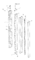
- FIG. 2 is an exploded perspective view showing a structure of the rotating bar of the refrigerator of FIG. 1
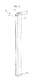
- FIG. 3 is an assembled perspective view of the rotating bar of the refrigerator of FIG. 1
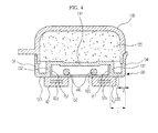
- FIG. 4 is a cross-sectional view of the rotating bar of the refrigerator of FIG. 1 .
- the rotating bar 100 includes a case 110 having an accommodating space 110a and provided with one surface thereof open, a heat insulation member 120 accommodated in the accommodating space 110a of the case 110, a cover 130 coupled to the one open surface of the case 110, a metallic plate 150 coupled to an outer side of the cover 130, and a heat generating member 140 disposed at a space in between the cover 130 and the metallic plate 150.
- the case 110 is configured to form an external appearance of the rotating bar 100, and may be provided at an inside thereof with the accommodating space 110a having one surface open, and the one open surface of the rotating bar 100 may be covered by the cover 130.
- a hinge bracket coupling part 110b to which a hinge bracket (70 in FIG. 6 ) is coupled may be provided at the case 110.
- the hinge bracket 70 may include a fixing part (71 in FIG. 6 ) fixed to the rear surface of the first door 40, and a hinge bar (72 in FIG. 6 ) configured to connect the fixing part 71 to the rotating bar 100, so that the rotating bar 100 is rotated on a rotation shaft (73 in FIG. 6 ).
- the fixing part 71 may be coupled to the rear surface of the first door 40 by use of a connecting member such as a screw.
- a passage part 112 may be provided, so that an insertion protrusion 161 being inserted into the guide groove (62 in FIG. 6 ) of the guide part (60 in FIG. 6 ) may be protruded to an outside the case 110.
- the passage part 112 may be provided in the form of a hole having the same shape as the insertion protrusion 161.
- the guide part 60 is formed at an upper portion of the body 10 while the insertion protrusion 161 is protruding from an upper side of the rotating bar 100.
- the guide part 60 may be formed at a lower portion of the body 10 while the insertion protrusion 161 may be protruding from a lower side of the rotating bar 100.
- the passage part 112 of the case 110 may also be formed at a lower surface of the case 110.
- the case 110 as such may be injection-molded using plastic material as an integrated body.
- the heat insulation member 120 is configured to thermally insulate the refrigerating compartment 20, and may be formed of EPS (Expanded PolyStyrene) material having superior insulation performance and light weight.
- EPS Expanded PolyStyrene
- the heat insulation member 120 after being formed in an approximate shape to be inserted into the accommodating space 110a of the case 110, is inserted into the accommodating space 110a of the case 110.
- the cover 130 is configured to cover the one surface of the case 110 that is open, and is coupled to the one open surface of the case 110 after the heat insulation member 120 is inserted into the accommodating space 110a of the case 110.
- the cover 130 is provided with a cross section obtained by being bent several times, and forms a portion of the side surface and a portion of the rear surface of the rotating bar 100.
- the rear surface of the rotating bar 100 is referred to as a surface facing the gaskets 42 and 52 of the doors 41 and 51.
- the cover 130 includes a heat insulation member adhering part 131 making contact with the heat insulation member 120, a second coupling part 132 to which the metallic plate 150, which will be described later, is coupled, a heat conduction blocking part 133 protruded toward the metallic plate 150, and a side surface forming part 134 forming at least one portion of the side surface of the rotating bar 100.
- the cover 130 may be injection molded using plastic material having low heat conductivity as an integrated body.
- the metallic plate 150 may be coupled to an outer side of the cover 130 as such, and the metallic plate 150 is formed of metallic material so as to come into close contact with the gaskets 42 and 52 by the magnetic force of the magnets 42a and 52a included in the gaskets 42 and 52, and to provide rigidity to the rotating bar 100.
- the metallic plate 150 may include a first coupling part 151 being coupled to the second coupling part 132 of the cover 130, and a gasket close-contact part 152 coming into close contact with the gaskets 42 and 52.
- the first coupling part 151 of the metallic plate 150 is coupled to the second coupling part 132 of the cover 130 by a connecting member such as a screw or by an adhesive member.
- the heat generating member 140 which is configured to generate heat to prevent frost from being formed on the metallic plate 150 due to the temperature difference between the inside and the outside the refrigerating compartment 40, may be disposed at a space formed by the first coupling part 151 of the metallic plate 150 and the gasket close-contact part 152 of the metallic plate 150.
- the heat generating member 140 may be implemented by a heating cable 140, which includes a heating wire covered with non-conductive material such as silicon or an FEP (Fluorinated Ethylene Propylene).
- a heating cable 140 which includes a heating wire covered with non-conductive material such as silicon or an FEP (Fluorinated Ethylene Propylene).
- the heat generating member 140 so as to deliver the minimum amount of heat to the metallic plate 150 to prevent frost from being formed on the metallic plate 150, may be disposed in a line-contacted manner with the metallic plate 150 instead of being surface-contacted with the metallic plate 150.
- the heat conduction blocking part 133 of the cover 130 and the gasket close-contact part 152 of the metallic plate 150 form the rear surface of the rotating bar 100.
- the central portion of the rear surface of the rotating bar 100 is formed by the gasket close-contact part 152 of the metallic plate 150, and both side edge portions of the rear surface of the rotating bar 100 are formed by the heat conduction blocking part 133 of the cover 130.
- the heat conduction blocking part 133 of the cover 130 is needed to be provided for a predetermined length L.
- the length L of the heat conduction blocking part 133 of the cover 130 is provided to be approximately larger than a wall thickness D of the cover 130, and within the limit that the metallic plate 150 comes into close contact with the gaskets 42 and 52 by the magnetic force of the magnets 42a and 52a that are included in the gaskets 42 and 52, the length of the gasket close-contact part 152 of the metallic plate 150 may be reduced while increasing the length L of the heat conduction blocking part 133 of the cover 130.
- the rotating bar 100 may seal the gap between the first door 40 and the second door 50 while coming into close contact with the gaskets 42 and 52 of the first door 40 and the second door 50, and may also minimize the heat, which is generated from the heat generating member 140 of the rotating bar 100, from penetrating to an inside the refrigerating compartment 20.
- the insulation performance of the rotating bar 100 is enhanced while the heat loss of the heat generating member 140 is minimized, thereby able to save the energy needed to prevent frost from being formed on the rotating bar 100.
- sealing members (170 and 180 in FIG. 2 ) may be provided at an upper end and at a lower end of the rotating bar 100, respectively, to seal a gap formed between the rotating bar 100 and the body 10 in a state that the doors 40 and 50 are closed.
- the sealing member 170 of the upper end and the sealing member 180 of the lower end may include blocking walls 171 and 181, respectively, which protrude to seal the gap in between the guide part 60 of the body 10 and the rotating bar 100 in a state that the door 40 is closed.
- the sealing member 170 may seal the gap between the guide part 60 and the rotating bar 100.
- the sealing members 170 and 180 as such may be formed of flexible material such as rubber to seal the gap between the body 10 and the rotating bar 100 in a smooth manner without damage by a collision.
- the rotating bar 100 includes a case 110 provided with an accommodating space formed at an inside thereof and having one surface thereof open, a heat insulation member 120 accommodated in the accommodating space of the case 110, a metallic plate 150 coupled to the one open surface of the case 110, a heat generating member 140 configured to radiate heat to prevent frost from being formed on the metallic plate 150, and a heat insulation film 190 formed on a surface of the metallic plate 150 that is exposed to the outside.
- the heat insulation film 190 is configured to increase the heat resistance of the metallic plate 150 so as to prevent the heat generated at the heat generating member 140 from penetrating to the refrigerating compartment 20 after being delivered along the metallic plate 150 to the both side surfaces of the rotating bar, and the heat insulation film 190 may be formed of material having a low heat conductivity.
- the heat insulation film 190 may be formed on the surface of the metallic plate 150 through a method such as a coating, or may be formed by attaching processed material having a shape of a thin panel to the metallic plate 150.
- the heat insulation film 190 is needed to be provided with a thickness less than a predetermined thickness, so that, in a state of the first door 40 and the second door 50 are closed, the rotating bar may come into close contact with the gaskets 42 and 52 by the magnetic force of the magnets 42a and 52a that are included in the gaskets 42 and 52.
- a heating cable may be used, and by being line-contacted with the metallic plate 150, may supply the minimum amount of heat needed to prevent frost from being formed at the metallic plate 150.
- the heat generating member 140 except for the area that is being line-contacted with the metallic plate 150, is disposed in a way to be surrounded by the heat insulation member 120, thereby minimizing heat loss.
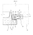
- FIGS. 6 to 9 are drawings to describe the operation of the rotating bar of the refrigerator of FIG. 1 . Referring to FIGS. 6 to 9 , the operation of the rotating bar of the refrigerator in accordance with one embodiment of the present disclosure will be described in brief.
- FIG. 6 illustrates a normal position of the rotating bar 100 in a state that the door 40 is open
- FIG. 7 illustrates a process of the first door 40 being closed from the state of FIG. 6
- FIG. 8 illustrates a state of the first door 40 and the second door 50 closed.
- FIG. 9 illustrates an abnormal position of the rotating bar 100 in a state that the first door 40 is open.
- the normal position of the rotating bar 100 is a position at which the rear surface of the rotating bar 100 is approximately perpendicular to first door 40.
- the position as such is referred to as a perpendicular position.
- the insertion protrusion 161 of the rotating bar 100 may enter an inside the guide groove 62 through a guide groove entry 63 of the guide part 60 that is provided at the body 10.
- the insertion protrusion 161 that enters an inside the guide groove 62 is rotated along the curved surface of the guide groove 62, and as the insertion protrusion 161 rotates, the rotating bar 100 is also rotated.
- the rotating bar 100 in the order of sequence of FIG. 8 , FIG. 7 , and FIG. 6 , is rotated in the counter-clockwise direction with respect to the drawings, and in the state of the first door 40 is completely open, the rotating bar 100 is disposed in a position essentially perpendicular with respect to first and second door.
- the first door 40 even in a state of the second door 50 being closed, may be closed without having the rotating bar 100 being interfered by the second door 50, and in addition, the insertion protrusion 161 of the rotating bar 100 may enter the guide groove 62 through the guide groove entry 63.
- the rotating bar 100 may be disposed at the parallel position due to an erroneous operation by a user. In this case, in the process of the first door 40 being closed, the rotating bar 100 may be interfered by the second door 50. In addition, even if the rotating bar 100 does not interfere with the second door 50 since the second door 50 is open, the insertion protrusion 161 may not be able to enter the guide groove 62 through the guide groove entry part 63, and may collide with the guide body 61.
- the first door 40 is not being completed closed, and the cool air of the refrigerating compartment 20 may be discharged, thereby causing a damage on the insertion protrusion 161.
- the insertion protrusion 161 of the rotating bar 100 of the refrigerator in accordance with one embodiment of the present disclosure is configured to be vertically movable, so that the insertion protrusion 161 is inserted into the guide groove 62 without being collided with the guide body 61 even in a state of the rotating bar 100 being in the parallel position.
- the structure of the insertion protrusion 161 as such will be described hereinafter.
- FIG. 10 is a drawing showing a structure of the insertion protrusion of the rotating bar of the refrigerator of FIG. 1
- FIGS. 11 to 12 are drawings to describe a vertical movement of the insertion protrusion of the rotating bar of the refrigerator of FIG. 1 .
- the insertion protrusion 161 includes a body part 166 disposed at an inside the rotating bar 100, a protrusion part 164 protruded to the outside the rotating bar 100 through the passage part 112 of the rotating bar 100, a stopper part 165 to prevent the insertion protrusion 161 from being separated from the rotating bar 100, and an inclined surface 163 formed at the protrusion part 164.
- the body part 166 is provided at an inside thereof with a hollowness into which an elastic member 162 may be inserted, and the insertion protrusion 161 is elastically biased by the elastic member 162 in a state of that the protrusion part 164 protrudes to the outside the rotating bar 100.
- a supporting part 111 to support the elastic member 162 provided, and a supporting pin 111a protruding from the supporting part 111 are provided.
- a supporting pin 166a is provided to support the elastic member 162.
- the protrusion part 164 is provided with an approximately same shape as the passage part 112 while provided with a size smaller than the size of the passage part 112 so as to be able to pass through the passage part 112.
- the protrusion part 164 may be provided with the stopper part 165 to limit the protrusion range of the protrusion part 164 to the outside of the protrusion part 164.
- the inclined surface 163 formed at the protrusion part 164 is configured to convert horizontal force into vertical force, and is configured in a way that the insertion protrusion 161 may move vertically by a horizontal pressing force of the guide body 61 in the process of the first door 40 being closed while the rotating bar 100 is at the parallel position.
- the insertion protrusion 161 ascends by the restoration force of the elastic member 162, and may be inserted into the guide groove 62.
- the first door 40 of the refrigerator in accordance with one embodiment of the present disclosure even in a state that the rotating bar 100 is rotated to the parallel position, may be closed without interference.
- the user convenience is enhanced, and the cool air loss due to the incomplete closing of the doors 40 and 50 may be prevented.
Abstract
Description
- Embodiments of the present disclosure relate to a refrigerator having a rotating bar configured to seal a gap formed between a pair of doors thereof.
- In general, a refrigerator is a household appliance having a storage compartment to store food, and a cool air supplying apparatus to supply cool air to the storage compartment to store the food in a fresh manner. The refrigerator, according to the storage compartment and a door thereof, may be classified into different types.
- A TMF (Top Mounted Freezer)-type refrigerator is provided therein with a storage compartment that is divided into an upper side and a lower side by a horizontal partition while a freezing compartment is formed at the upper side and a refrigerating compartment is formed at the lower side, and a BMF (Bottom Mounted Freezer-type refrigerator is provided with a refrigerating compartment formed at the upper side while a freezing compartment is formed at the lower side.
- In addition, a SBS (Side By Side)-type refrigerator is provided therein with a storage compartment that is divided into an left side and a right side by a vertical partition while a freezing compartment is formed at one side and a refrigerating compartment is formed at the other side, and a FDR (French Door Refrigerator)-type refrigerator is provided therein with a storage compartment that is divided into an upper side and a lower side by a horizontal partition while a refrigerating compartment is formed at the upper side and a freezing compartment is formed at the lower side, as the refrigerating compartment at the upper side is open/closed by a pair of doors.
- Meanwhile, a gasket is provided at a door of a refrigerator to seal a gap which is formed between the door and the body of the refrigerator when the door is closed. However, with respect to the FDR-type refrigerator, the refrigerating compartment at the upper side is open and closed by a pair of doors, but the refrigerating compartment is not provided therein with a vertical partition, and thus a gap formed between the pair of doors may not be sealed by the gasket. In order to seal the gap between the pair of doors, a rotating bar rotatably installed at one of the pair of the doors is suggested.
- The rotating bar as such, when the pair of doors is closed, is being rotated in a horizontal state with respect to the pair of doors to seal the gap in between the pair of doors, and when one door provided with the rotating bar installed thereto is open, the rotating bar is being rotated to a vertical state with respect to the other door, so that the rotating bar is not being interfered at the other door, which is not provided with the rotating bar installed thereto.
- Meanwhile, the rotating bar includes a heat insulation member configured to block cool air from being discharged from a storage compartment, a metal plate formed of metal so as to come into close contact with a gasket installed at a rear surface of the door, and a heat generating member configured to radiate heat to prevent the frost from being formed at the plate.
- It is an object of the present disclosure to provide a rotating bar having an enhanced insulation performance, and capable of sealing a gap between the rotating bar and a body as well as a gap between one pair of doors.
- It is another object of the present disclosure to provide a rotating bar enabling an insertion protrusion of the rotating bar to be inserted into a guide part regardless of the position of the rotating bar.
- Additional aspects of the disclosure will be set forth in part in the description which follows and, in part, will be apparent from the description, or may be learned by practice of the disclosure.
- This object is solved by the features of the independent claims.
- Advantageous embodiment are disclosed by the subclaims.
- According to the invention, with respect to the rotating bar for sealing a gap between one pair of doors, the doors are prevented from being incompletely closed due to an erroneous operation of the rotating bar, and the convenience of use is improved.
- In addition, the rotating bar seals a gap between the rotating bar and the door as well as a gap between one pair of doors, thereby improving the heat insulation efficiency of the storage compartment.
- These and/or other aspects of the disclosure will become apparent and more readily appreciated from the following description of the embodiments, taken in conjunction with the accompanying drawings of which:
-
FIG. 1 is a drawing illustrating a front of a refrigerator in accordance with one aspect of the present disclosure. -
FIG. 2 is an exploded perspective view showing a structure of a rotating bar of the refrigerator ofFIG. 1 . -
FIG. 3 is an assembled perspective view of the rotating bar of the refrigerator ofFIG. 1 . -
FIG. 4 is a cross-sectional view of the rotating bar of the refrigerator ofFIG. 1 . -
FIG. 5 is a cross-sectional view of a rotating bar of a refrigerator in accordance with another aspect of the present disclosure. -
FIGS. 6 to 9 are drawings to describe the operation of the rotating bar of the refrigerator ofFIG. 1 . -
FIG. 10 is a drawing showing a structure of an insertion protrusion of the rotating bar of the refrigerator ofFIG. 1 . -
FIGS. 11 to 12 are drawings to describe a vertical movement of the insertion protrusion of the rotating bar of the refrigerator ofFIG. 1 . - Reference will now be made in detail to the embodiments of the present disclosure, examples of which are illustrated in the accompanying drawings, wherein like reference numerals refer to like elements throughout.
-
FIG. 1 is a drawing illustrating a front of a refrigerator in accordance with one aspect of the present disclosure. Referring toFIG. 1 , arefrigerator 1 in accordance with one embodiment of the present disclosure includes abody 10,storage compartments body 10,doors storage compartments storage compartments - The
body 10 may include an inner case forming thestorage compartments storage compartments - The cool air supplying apparatus (not shown) may generate cool air by using a cooling circulation cycle configured to compress, condense, expand, and evaporate refrigerant.
- The
storage compartments compartment 20 at the upper side and thefreezing compartment 30 at the lower side. The refrigeratingcompartment 20 may be open and closed by the pair ofdoors body 10, and thefreezing compartment 30 may be open and closed by the slidingdoor 31 slidably mounted at thebody 10. - The pair of
doors compartment 20 may be disposed side by side. Hereinafter, for the sake of convenience, theleft side door 40 on the drawing is referred to as thefirst door 40 and theright side door 50 on the drawing is referred to as thesecond door 50. - The
first door 40 is configured to open and close a left portion of the front surface of the refrigeratingcompartment 20 that is open, and thesecond door 50 is configured to open and close the remaining portion of the front surface of the refrigeratingcompartment 20 that is open.Door shelves first door 40 and thesecond door 50, respectively, to store foods. In addition, at the rims of the rear surfaces of thefirst door 40 and thesecond door 50,gaskets body 10 in a state that thefirst door 40 and thesecond door 50 are closed. - The
gaskets first door 40 and thesecond door 50, respectively, and magnets (42a and 52a inFIGS. 4 and5 ) may be included at an inside thegaskets - Meanwhile, in a state that the
first door 40 and thesecond door 50 are closed, a gap may be formed between thefirst door 40 and thesecond door 50, and in order to seal the gap as such, a rotatingbar 100 is rotatably mounted at thefirst door 40. - The rotating
bar 100 as such is provided in a bar shape formed lengthwise along the height direction of thefirst door 40, and may be rotated by aguide part 60 provided at thebody 10. Theguide part 60 of thebody 10 may include a guide body (61 inFIG. 6 ) coupled to thebody 10, and a guide groove (62 inFIG. 6 ) formed at theguide body 61. Hereinafter, the structure and the operation of the rotatingbar 100 as such will be described. -
FIG. 2 is an exploded perspective view showing a structure of the rotating bar of the refrigerator ofFIG. 1 ,FIG. 3 is an assembled perspective view of the rotating bar of the refrigerator ofFIG. 1 , andFIG. 4 is a cross-sectional view of the rotating bar of the refrigerator ofFIG. 1 . - Referring to
FIGS. 2 to 4 , the rotatingbar 100 includes acase 110 having anaccommodating space 110a and provided with one surface thereof open, aheat insulation member 120 accommodated in theaccommodating space 110a of thecase 110, acover 130 coupled to the one open surface of thecase 110, ametallic plate 150 coupled to an outer side of thecover 130, and aheat generating member 140 disposed at a space in between thecover 130 and themetallic plate 150. - The
case 110 is configured to form an external appearance of therotating bar 100, and may be provided at an inside thereof with theaccommodating space 110a having one surface open, and the one open surface of the rotatingbar 100 may be covered by thecover 130. A hingebracket coupling part 110b to which a hinge bracket (70 inFIG. 6 ) is coupled may be provided at thecase 110. - The
hinge bracket 70 may include a fixing part (71 inFIG. 6 ) fixed to the rear surface of thefirst door 40, and a hinge bar (72 inFIG. 6 ) configured to connect thefixing part 71 to therotating bar 100, so that therotating bar 100 is rotated on a rotation shaft (73 inFIG. 6 ). Thefixing part 71 may be coupled to the rear surface of thefirst door 40 by use of a connecting member such as a screw. - In addition, at an upper surface of the
case 110, apassage part 112 may be provided, so that aninsertion protrusion 161 being inserted into the guide groove (62 inFIG. 6 ) of the guide part (60 inFIG. 6 ) may be protruded to an outside thecase 110. Thepassage part 112 may be provided in the form of a hole having the same shape as theinsertion protrusion 161. - In the embodiment of the present disclosure, the
guide part 60 is formed at an upper portion of thebody 10 while theinsertion protrusion 161 is protruding from an upper side of therotating bar 100. However, theguide part 60 may be formed at a lower portion of thebody 10 while theinsertion protrusion 161 may be protruding from a lower side of the rotatingbar 100. In this case, thepassage part 112 of thecase 110 may also be formed at a lower surface of thecase 110. Thecase 110 as such may be injection-molded using plastic material as an integrated body. - The
heat insulation member 120 is configured to thermally insulate the refrigeratingcompartment 20, and may be formed of EPS (Expanded PolyStyrene) material having superior insulation performance and light weight. Theheat insulation member 120, after being formed in an approximate shape to be inserted into theaccommodating space 110a of thecase 110, is inserted into theaccommodating space 110a of thecase 110. - The
cover 130 is configured to cover the one surface of thecase 110 that is open, and is coupled to the one open surface of thecase 110 after theheat insulation member 120 is inserted into theaccommodating space 110a of thecase 110. - As illustrated on
FIG. 4 , thecover 130 is provided with a cross section obtained by being bent several times, and forms a portion of the side surface and a portion of the rear surface of therotating bar 100. Here, the rear surface of therotating bar 100 is referred to as a surface facing thegaskets doors - In detail, the
cover 130 includes a heat insulationmember adhering part 131 making contact with theheat insulation member 120, asecond coupling part 132 to which themetallic plate 150, which will be described later, is coupled, a heatconduction blocking part 133 protruded toward themetallic plate 150, and a sidesurface forming part 134 forming at least one portion of the side surface of therotating bar 100. Thecover 130 may be injection molded using plastic material having low heat conductivity as an integrated body. - The
metallic plate 150 may be coupled to an outer side of thecover 130 as such, and themetallic plate 150 is formed of metallic material so as to come into close contact with thegaskets magnets gaskets rotating bar 100. - The
metallic plate 150 may include afirst coupling part 151 being coupled to thesecond coupling part 132 of thecover 130, and a gasket close-contact part 152 coming into close contact with thegaskets first coupling part 151 of themetallic plate 150 is coupled to thesecond coupling part 132 of thecover 130 by a connecting member such as a screw or by an adhesive member. - Meanwhile, the
heat generating member 140, which is configured to generate heat to prevent frost from being formed on themetallic plate 150 due to the temperature difference between the inside and the outside the refrigeratingcompartment 40, may be disposed at a space formed by thefirst coupling part 151 of themetallic plate 150 and the gasket close-contact part 152 of themetallic plate 150. - Here, so as to prevent the heat generated from the
heat generating member 140 from being excessively delivered to themetallic plate 150, theheat generating member 140 may be implemented by aheating cable 140, which includes a heating wire covered with non-conductive material such as silicon or an FEP (Fluorinated Ethylene Propylene). - Thus, the
heat generating member 140, so as to deliver the minimum amount of heat to themetallic plate 150 to prevent frost from being formed on themetallic plate 150, may be disposed in a line-contacted manner with themetallic plate 150 instead of being surface-contacted with themetallic plate 150. - Meanwhile, the heat
conduction blocking part 133 of thecover 130 and the gasket close-contact part 152 of themetallic plate 150, both of which were previously described, form the rear surface of therotating bar 100. The central portion of the rear surface of therotating bar 100 is formed by the gasket close-contact part 152 of themetallic plate 150, and both side edge portions of the rear surface of therotating bar 100 are formed by the heatconduction blocking part 133 of thecover 130. - In order to prevent the heat, which is being conducted along the gasket close-
contact part 152 of themetallic plate 150, from being conducted to the side surface of therotating bar 100, the heatconduction blocking part 133 of thecover 130 is needed to be provided for a predetermined length L. - The length L of the heat
conduction blocking part 133 of thecover 130 is provided to be approximately larger than a wall thickness D of thecover 130, and within the limit that themetallic plate 150 comes into close contact with thegaskets magnets gaskets contact part 152 of themetallic plate 150 may be reduced while increasing the length L of the heatconduction blocking part 133 of thecover 130. - According to the structure as the above, in a state where the
first door 40 and thesecond door 50 are closed, the rotatingbar 100 may seal the gap between thefirst door 40 and thesecond door 50 while coming into close contact with thegaskets first door 40 and thesecond door 50, and may also minimize the heat, which is generated from theheat generating member 140 of therotating bar 100, from penetrating to an inside the refrigeratingcompartment 20. - Thus, the insulation performance of the
rotating bar 100 is enhanced while the heat loss of theheat generating member 140 is minimized, thereby able to save the energy needed to prevent frost from being formed on therotating bar 100. - Meanwhile, sealing members (170 and 180 in
FIG. 2 ) may be provided at an upper end and at a lower end of therotating bar 100, respectively, to seal a gap formed between therotating bar 100 and thebody 10 in a state that thedoors - The sealing
member 170 of the upper end and the sealingmember 180 of the lower end may include blockingwalls 171 and 181, respectively, which protrude to seal the gap in between theguide part 60 of thebody 10 and therotating bar 100 in a state that thedoor 40 is closed. - As illustrated in one embodiment shown in
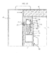
FIG. 12 of the present disclosure, in a case when theguide part 60 is provided at an upper portion of thebody 10, the sealingmember 170 may seal the gap between theguide part 60 and therotating bar 100. - The sealing
members body 10 and therotating bar 100 in a smooth manner without damage by a collision. - Hereinafter, the structure of a rotating bar in accordance with another embodiment of the present disclosure will be described with reference to
FIG. 5 . In the following description, the same reference numerals will be assigned to the parts of the present embodiment that are identical to those according to the previous embodiment, and details of parts will be omitted in order to avoid redundancy. - In accordance with another embodiment of the present disclosure, the rotating
bar 100 includes acase 110 provided with an accommodating space formed at an inside thereof and having one surface thereof open, aheat insulation member 120 accommodated in the accommodating space of thecase 110, ametallic plate 150 coupled to the one open surface of thecase 110, aheat generating member 140 configured to radiate heat to prevent frost from being formed on themetallic plate 150, and aheat insulation film 190 formed on a surface of themetallic plate 150 that is exposed to the outside. - The
heat insulation film 190 is configured to increase the heat resistance of themetallic plate 150 so as to prevent the heat generated at theheat generating member 140 from penetrating to therefrigerating compartment 20 after being delivered along themetallic plate 150 to the both side surfaces of the rotating bar, and theheat insulation film 190 may be formed of material having a low heat conductivity. - The
heat insulation film 190 may be formed on the surface of themetallic plate 150 through a method such as a coating, or may be formed by attaching processed material having a shape of a thin panel to themetallic plate 150. - However, the
heat insulation film 190 is needed to be provided with a thickness less than a predetermined thickness, so that, in a state of thefirst door 40 and thesecond door 50 are closed, the rotating bar may come into close contact with thegaskets magnets gaskets - As for the
heat generating member 140, a heating cable may be used, and by being line-contacted with themetallic plate 150, may supply the minimum amount of heat needed to prevent frost from being formed at themetallic plate 150. Theheat generating member 140, except for the area that is being line-contacted with themetallic plate 150, is disposed in a way to be surrounded by theheat insulation member 120, thereby minimizing heat loss. -
FIGS. 6 to 9 are drawings to describe the operation of the rotating bar of the refrigerator ofFIG. 1 . Referring toFIGS. 6 to 9 , the operation of the rotating bar of the refrigerator in accordance with one embodiment of the present disclosure will be described in brief. -
FIG. 6 illustrates a normal position of therotating bar 100 in a state that thedoor 40 is open,FIG. 7 illustrates a process of thefirst door 40 being closed from the state ofFIG. 6 , andFIG. 8 illustrates a state of thefirst door 40 and thesecond door 50 closed. -
FIG. 9 illustrates an abnormal position of therotating bar 100 in a state that thefirst door 40 is open. - As illustrated on
FIG. 6 , in a state that thefirst door 40 is open, the normal position of therotating bar 100 is a position at which the rear surface of therotating bar 100 is approximately perpendicular tofirst door 40. Hereinafter, the position as such is referred to as a perpendicular position. - In a state that the
rotating bar 100 is at the vertical position, as thefirst door 40 is closed, as illustrated onFIG. 7 , theinsertion protrusion 161 of therotating bar 100 may enter an inside theguide groove 62 through aguide groove entry 63 of theguide part 60 that is provided at thebody 10. - The
insertion protrusion 161 that enters an inside theguide groove 62 is rotated along the curved surface of theguide groove 62, and as theinsertion protrusion 161 rotates, the rotatingbar 100 is also rotated. - Finally, as illustrated on
FIG. 8 , when thefirst door 40 is completely closed, the rear surface of rotatingbar 100 is disposed in an approximately parallel position with respect to thefirst door 40 and of thesecond door 50, and thus therotating bar 100 comes into close contact with thegaskets first door 40 and thesecond door 50. Hereinafter, this position of therotating bar 100 will be referred to as a parallel position. - Finally, in the process of the
first door 40 being closed, the rotatingbar 100, in the order of sequence as illustrated onFIG. 6 ,FIG. 7 , andFIG. 8 , is rotated in clockwise direction on the drawings. - In addition, on the contrary, in the process of the
first door 40 being open, the rotatingbar 100, in the order of sequence ofFIG. 8 ,FIG. 7 , andFIG. 6 , is rotated in the counter-clockwise direction with respect to the drawings, and in the state of thefirst door 40 is completely open, the rotatingbar 100 is disposed in a position essentially perpendicular with respect to first and second door. - As the above, as the
rotating bar 100 is disposed at the perpendicular position, thefirst door 40, even in a state of thesecond door 50 being closed, may be closed without having therotating bar 100 being interfered by thesecond door 50, and in addition, theinsertion protrusion 161 of therotating bar 100 may enter theguide groove 62 through theguide groove entry 63. - However, in a state that the
first door 40 is open, the rotatingbar 100 may be disposed at the parallel position due to an erroneous operation by a user. In this case, in the process of thefirst door 40 being closed, the rotatingbar 100 may be interfered by thesecond door 50. In addition, even if therotating bar 100 does not interfere with thesecond door 50 since thesecond door 50 is open, theinsertion protrusion 161 may not be able to enter theguide groove 62 through the guidegroove entry part 63, and may collide with theguide body 61. - Thus, the
first door 40 is not being completed closed, and the cool air of therefrigerating compartment 20 may be discharged, thereby causing a damage on theinsertion protrusion 161. - Thus, the
insertion protrusion 161 of therotating bar 100 of the refrigerator in accordance with one embodiment of the present disclosure is configured to be vertically movable, so that theinsertion protrusion 161 is inserted into theguide groove 62 without being collided with theguide body 61 even in a state of therotating bar 100 being in the parallel position. The structure of theinsertion protrusion 161 as such will be described hereinafter. -
FIG. 10 is a drawing showing a structure of the insertion protrusion of the rotating bar of the refrigerator ofFIG. 1 , andFIGS. 11 to 12 are drawings to describe a vertical movement of the insertion protrusion of the rotating bar of the refrigerator ofFIG. 1 . - Referring to
FIGS. 10 to 12 , theinsertion protrusion 161 includes abody part 166 disposed at an inside therotating bar 100, aprotrusion part 164 protruded to the outside the rotatingbar 100 through thepassage part 112 of therotating bar 100, astopper part 165 to prevent theinsertion protrusion 161 from being separated from therotating bar 100, and aninclined surface 163 formed at theprotrusion part 164. - The
body part 166 is provided at an inside thereof with a hollowness into which anelastic member 162 may be inserted, and theinsertion protrusion 161 is elastically biased by theelastic member 162 in a state of that theprotrusion part 164 protrudes to the outside the rotatingbar 100. - At the
case 110 of therotating bar 100, a supportingpart 111 to support theelastic member 162 provided, and a supportingpin 111a protruding from the supportingpart 111 are provided. At thebody part 166, a supportingpin 166a is provided to support theelastic member 162. - The
protrusion part 164 is provided with an approximately same shape as thepassage part 112 while provided with a size smaller than the size of thepassage part 112 so as to be able to pass through thepassage part 112. Theprotrusion part 164 may be provided with thestopper part 165 to limit the protrusion range of theprotrusion part 164 to the outside of theprotrusion part 164. - The
inclined surface 163 formed at theprotrusion part 164 is configured to convert horizontal force into vertical force, and is configured in a way that theinsertion protrusion 161 may move vertically by a horizontal pressing force of theguide body 61 in the process of thefirst door 40 being closed while therotating bar 100 is at the parallel position. - Thus, as illustrated on
FIG. 9 , if thefirst door 40 is closed in a state of therotating bar 100 is at the parallel position, theinsertion protrusion 161 collides with theguide body 61, and descends by the pressing force of theguide body 61. - In the state as such, when the
first door 40 is completely closed, theinsertion protrusion 161 ascends by the restoration force of theelastic member 162, and may be inserted into theguide groove 62. - According to the structure as the above, the
first door 40 of the refrigerator in accordance with one embodiment of the present disclosure, even in a state that therotating bar 100 is rotated to the parallel position, may be closed without interference. Thus, the user convenience is enhanced, and the cool air loss due to the incomplete closing of thedoors - Although a few embodiments of the present disclosure have been shown and described, it would be appreciated by those skilled in the art that changes may be made in these embodiments without departing from the principles and spirit of the disclosure, the scope of which is defined in the claims and their equivalents.
Claims (17)
- A rotating bar (100) formed in between doors (40, 50) of a refrigerator (1) to close a gap therebetween, the refrigerator including a guide part (60) provided at a body (10) of the refrigerator (1) to guide a rotation of the rotating bar (100), the guide part including a guide body part (61) fixed to the body and a guide groove (62) formed in the guide body part, the rotating bar (100) comprising:a case (110) rotatably coupled to one of the doors (40, 50);a heat insulation member (120) accommodated within the case;an insertion protrusion (161) configured to be elastically biased toward an outer side of the case (110) so as to be inserted into the guide groove (62), and upon exertion of external force, configured to move toward an inner side of the case (110),a metallic plate (150) coupled to the case (110); anda heat generating member (140) configured to prevent frost from being formed on the metallic plate (150).
- The rotating bar of claim 1, further comprising a heat insulation film (190) formed on an outer surface of the metallic plate (150).
- The rotating bar of claim 1, wherein the heat generating member (140) comprises a heating cable, the heating cable being in line-contact with the metallic plate (150).
- The rotating bar of claim 1, wherein the insertion protrusion (161) is configured to enter the guide groove through an entry of the guide groove (162) and travel along a curved surface of the guide groove to rotate the rotating bar from being perpendicular to the refrigerator to being parallel with the refrigerator to thereby seal the gap between the doors of the refrigerator; and
the insertion protrusion (161) is configured to move toward the inner side of the case by the external force of the guide body part (61) to avoid an interference with the guide body part and move toward the outer side of the case by the elastic force so as to be inserted into the guide groove (62) if the rotating bar approaches the entry of the guide groove parallel to the refrigerator. - The rotating bar of claim 1, wherein the insertion protrusion (161) at least comprises:a protrusion part (164) configured to be inserted into the guide groove (62);an elastic member (162) configured to elastically support the protrusion part (164) such that the protrusion part protrudes toward the outer side of the case; anda stopper part (165) configured to prevent the protrusion part from being separated to an outside the case.
- The rotating bar of claim 5, wherein the protrusion part (164) comprises an inclined surface (163) configured to allow the protrusion part to perform a vertical movement by a horizontal force exerted on the protrusion part.
- The rotating bar of claim 1, wherein the case (110) includes a passage part (112) to allow the insertion protrusion (164) to pass therethrough.
- The rotating bar of claim 1, wherein:the insertion protrusion (161) is provided on at least one of an upper end and a lower end of the rotating bar (100).
- The rotating bar of claim 5, wherein:a support part (111) configured to support the elastic member (162) is provided at the inner side of the case (110).
- The rotating bar of claim 1, wherein:the rotating bar (100) further comprises a sealing member (170, 180) having a blocking wall (171, 181) that protrudes to the outer side of the case (110) so as to seal a gap formed between the body (10) and the rotating bar (110).
- The rotating bar of claim 10, wherein:the sealing member (170, 180) is formed of rubber.
- A refrigerator (1), comprising:a body (10);a storage compartment (20) formed at an inside the body (10) while having a front surface thereof open;a first door (40) configured to open/close a portion of the front surface of the storage compartment (20) that is open;a second door (50) configured to open/close a remaining portion of the front surface of the storage compartment (20) that is open;a first gasket (42) installed at a rear surface of the first door to seal a gap formed between the first door and the body;a second gasket (52) installed at a rear surface of the second door to seal a gap formed between the second door and the body; andsaid rotating bar (100) according to one of the previous claims.
- The refrigerator of claim 12, wherein:if the first door (40) is closed in a state of the rotating bar (100) being rotated in perpendicular to the first door, the insertion protrusion (161) is configured to enter the guide groove (62) through an entry of the guide groove and is rotated along a curved surface of the guide groove; andif the first door (40) is closed in a state of the rotating bar being rotated in parallel to the first door, the insertion protrusion (161) moves toward the inner side of the case (110) by the external force of the guide body part (61) to avoid an interference with the guide body part and moves toward the outer side of the case by the elastic force so as to be inserted into the guide groove (62).
- A refrigerator (1), comprising:a body (10);a storage compartment (20) formed at an inside the body while having a front surface thereof open;a pair of doors (40, 50) rotatably coupled to the body (10) to open/close the front surface of the storage compartment (20) that is open;a rotating bar (100) rotatably coupled to one of the pair of doors (40, 50) to seal a gap formed between the pair of doors in a state that the pair of doors are closed; anda sealing member (170, 180) protruding from the rotating bar to seal a gap formed between the rotating bar and the body.
- The refrigerator of claim 14, further comprising:a guide part (60) provided at an upper side of the body (10) to guide a rotation of the rotating bar (100); andan insertion protrusion (161) protruding from an upper side of the rotating bar (100) so as to be rotated while being inserted into the guide part,wherein the insertion protrusion (161) is provided so as to enable a vertical movement.
- The refrigerator of claim 15, further comprising an elastic member (162) configured to elastically support the insertion protrusion (161) to the upper side.
- The refrigerator of claim 15, wherein the insertion protrusion (161) comprises an inclined surface (163) that allows the insertion protrusion to move in direction to the rotating bar (100) by a pressing force exerted in a horizontal direction.
Priority Applications (1)
| Application Number | Priority Date | Filing Date | Title |
|---|---|---|---|
| PL13159689T PL2639534T3 (en) | 2012-03-16 | 2013-03-18 | Heated rotating mullion bar and refrigerator comprising said bar. |
Applications Claiming Priority (1)
| Application Number | Priority Date | Filing Date | Title |
|---|---|---|---|
| KR1020120027185A KR101564911B1 (en) | 2012-03-16 | 2012-03-16 | Refrigerator |
Publications (3)
| Publication Number | Publication Date |
|---|---|
| EP2639534A2 true EP2639534A2 (en) | 2013-09-18 |
| EP2639534A3 EP2639534A3 (en) | 2017-01-11 |
| EP2639534B1 EP2639534B1 (en) | 2020-10-07 |
Family
ID=47900899
Family Applications (1)
| Application Number | Title | Priority Date | Filing Date |
|---|---|---|---|
| EP13159689.2A Active EP2639534B1 (en) | 2012-03-16 | 2013-03-18 | Heated rotating mullion bar and refrigerator comprising said bar. |
Country Status (9)
| Country | Link |
|---|---|
| US (3) | US9157676B2 (en) |
| EP (1) | EP2639534B1 (en) |
| KR (1) | KR101564911B1 (en) |
| CN (2) | CN103471325A (en) |
| AU (1) | AU2013232925B2 (en) |
| CA (1) | CA2866660C (en) |
| DE (2) | DE202013012861U1 (en) |
| PL (1) | PL2639534T3 (en) |
| WO (1) | WO2013137683A1 (en) |
Cited By (2)
| Publication number | Priority date | Publication date | Assignee | Title |
|---|---|---|---|---|
| US9841223B2 (en) | 2014-12-01 | 2017-12-12 | Samsung Electronics Co., Ltd. | Refrigerator |
| US10775095B2 (en) * | 2016-01-14 | 2020-09-15 | Lg Electronics Inc. | Refrigerator |
Families Citing this family (37)
| Publication number | Priority date | Publication date | Assignee | Title |
|---|---|---|---|---|
| US9506689B2 (en) * | 2013-07-11 | 2016-11-29 | Anthony International | Pivoting mullion for a temperature-controlled storage device |
| CN203572131U (en) * | 2013-07-31 | 2014-04-30 | 博西华电器(江苏)有限公司 | Refrigerator |
| CN103486806B (en) * | 2013-09-18 | 2015-09-09 | 泰州乐金电子冷机有限公司 | For refrigerator doors baffle plate sealing device and comprise its refrigerator |
| WO2015105305A1 (en) * | 2014-01-07 | 2015-07-16 | 삼성전자주식회사 | Refrigerator |
| KR102104521B1 (en) | 2014-01-07 | 2020-04-27 | 삼성전자주식회사 | Refrigerator |
| JP6334186B2 (en) * | 2014-02-05 | 2018-05-30 | 東芝ライフスタイル株式会社 | refrigerator |
| KR102332723B1 (en) * | 2014-03-11 | 2021-12-02 | 삼성전자주식회사 | Refrigerator |
| KR101620429B1 (en) * | 2014-04-18 | 2016-05-23 | 엘지전자 주식회사 | Refrigerator |
| KR101727045B1 (en) * | 2014-11-07 | 2017-04-14 | 엘지전자 주식회사 | Refrigerator |
| KR101644438B1 (en) * | 2014-11-20 | 2016-08-01 | 엘지전자 주식회사 | Refrigerator |
| KR101998566B1 (en) | 2014-11-26 | 2019-07-10 | 삼성전자주식회사 | Refrigerator |
| KR102196314B1 (en) * | 2014-12-17 | 2020-12-29 | 엘지전자 주식회사 | Refrigerator |
| CN104534796A (en) * | 2014-12-23 | 2015-04-22 | 合肥美的电冰箱有限公司 | Refrigerator and turning beam assembly thereof |
| KR102354521B1 (en) * | 2015-03-05 | 2022-01-24 | 엘지이노텍 주식회사 | Refrigerator |
| US9841225B2 (en) | 2015-03-20 | 2017-12-12 | Whirlpool Corporation | Low wattage flipper mullion |
| JP6613448B2 (en) * | 2015-06-29 | 2019-12-04 | パナソニックIpマネジメント株式会社 | refrigerator |
| KR20170027246A (en) * | 2015-09-01 | 2017-03-09 | 삼성전자주식회사 | Refrigerator |
| WO2017119599A1 (en) | 2016-01-04 | 2017-07-13 | 엘지전자 주식회사 | Refrigerator |
| KR102483708B1 (en) * | 2016-01-04 | 2023-01-02 | 엘지전자 주식회사 | Refrigerator |
| KR102548043B1 (en) * | 2016-01-21 | 2023-06-27 | 엘지전자 주식회사 | Refrigerator |
| JP6467593B2 (en) * | 2016-03-17 | 2019-02-13 | パナソニックIpマネジメント株式会社 | refrigerator |
| CN108253705B (en) * | 2016-12-28 | 2020-11-27 | 博西华电器(江苏)有限公司 | Refrigeration device |
| KR20180086733A (en) * | 2017-01-23 | 2018-08-01 | 삼성전자주식회사 | Refrigerator |
| US10130171B2 (en) | 2017-02-08 | 2018-11-20 | Intermetro Industries Corporation | Insulated transport cabinets for food and the like |
| US10317127B2 (en) | 2017-09-27 | 2019-06-11 | Haier Us Appliance Solutions, Inc. | Refrigerator appliances including a drawer assembly |
| US10422571B2 (en) | 2017-11-13 | 2019-09-24 | Midea Group Co., Ltd | Method and apparatus for sealing french doors for a freezer compartment |
| US10837695B2 (en) * | 2017-12-04 | 2020-11-17 | Electrolux Home Products, Inc. | Refrigerator assembly |
| CN108106311B (en) * | 2017-12-07 | 2020-10-09 | 合肥华凌股份有限公司 | Refrigerator with a door |
| SG11202009229UA (en) * | 2018-04-02 | 2020-10-29 | Mitsubishi Electric Corp | Refrigerator-freezer |
| JP6501943B2 (en) * | 2018-04-16 | 2019-04-17 | 東芝ライフスタイル株式会社 | refrigerator |
| KR102557949B1 (en) * | 2018-05-16 | 2023-07-21 | 삼성전자주식회사 | Refrigerator |
| EP3899387A1 (en) * | 2018-12-21 | 2021-10-27 | Arçelik Anonim Sirketi | A cooling appliance comprising a partition |
| JP6664020B2 (en) * | 2019-03-18 | 2020-03-13 | 東芝ライフスタイル株式会社 | refrigerator |
| US11168934B2 (en) * | 2020-01-23 | 2021-11-09 | Bsh Home Appliances Corporation | Extruded plastic front frame profiles for cooling appliances |
| US11906235B2 (en) * | 2020-02-05 | 2024-02-20 | Peter M. Osgard | Refrigeration door system and door assembly with defrosting and related methods |
| JP6876840B2 (en) * | 2020-02-17 | 2021-05-26 | 東芝ライフスタイル株式会社 | refrigerator |
| CN113790566B (en) * | 2021-09-01 | 2022-07-26 | 珠海格力电器股份有限公司 | Door body assembly and refrigeration equipment |
Family Cites Families (22)
| Publication number | Priority date | Publication date | Assignee | Title |
|---|---|---|---|---|
| US1918865A (en) * | 1930-05-28 | 1933-07-18 | Harley M Purdy | Spring-pressed weather strip and its spring-pressed actuator |
| US3045663A (en) * | 1959-09-28 | 1962-07-24 | Gen Motors Corp | Oven door mounting means |
| US4428153A (en) * | 1982-03-08 | 1984-01-31 | Atlanta Richfield Company | Recessed astragal for double door |
| US4711098A (en) * | 1985-10-11 | 1987-12-08 | Sanyo Electric Co., Ltd. | Refrigerator |
| JP2702756B2 (en) | 1988-10-31 | 1998-01-26 | 松下冷機株式会社 | Door devices such as refrigerators |
| JP3199390B2 (en) | 1991-01-29 | 2001-08-20 | 松下冷機株式会社 | Double door system |
| US5694789A (en) * | 1996-01-16 | 1997-12-09 | Lg Electronics Inc. | Cam operated door seal for refrigerator |
| CA2338807C (en) * | 2001-02-27 | 2004-07-06 | Camco Inc. | Refrigerator mullion |
| US7008032B2 (en) * | 2003-08-29 | 2006-03-07 | Maytag Corporation | Refrigerator incorporating french doors with rotating mullion bar |
| JP3944500B2 (en) * | 2004-09-10 | 2007-07-11 | 日立アプライアンス株式会社 | refrigerator |
| DE202006007336U1 (en) * | 2006-05-08 | 2006-07-13 | BSH Bosch und Siemens Hausgeräte GmbH | The refrigerator |
| KR20080065434A (en) * | 2007-01-09 | 2008-07-14 | 엘지전자 주식회사 | Door handle of refrigerator |
| GB2446047A (en) * | 2007-01-26 | 2008-07-30 | Fisher & Paykel Appliances Ltd | Refrigerator gasket having tabs with magnetic elements |
| KR20080079113A (en) * | 2007-02-26 | 2008-08-29 | 삼성전자주식회사 | Refrigerator |
| US20090273264A1 (en) * | 2008-05-02 | 2009-11-05 | James Christopher Butler | Flapper mechanism for a refrigerator |
| JP4859898B2 (en) * | 2008-09-18 | 2012-01-25 | 三菱電機株式会社 | Freezer refrigerator |
| KR101446493B1 (en) | 2008-09-25 | 2014-10-07 | 삼성전자주식회사 | Refrigerator |
| US8167389B2 (en) * | 2008-09-25 | 2012-05-01 | Samsung Electronics Co., Ltd. | Refrigerator mullion with protection unit |
| KR20110032898A (en) | 2009-09-24 | 2011-03-30 | 엘지전자 주식회사 | Refrigerator with a cooling air leakage preventing member |
| JP2011112290A (en) | 2009-11-27 | 2011-06-09 | Panasonic Corp | Refrigerator |
| KR20110072774A (en) | 2009-12-23 | 2011-06-29 | 엘지전자 주식회사 | Refrigerator and assemble method of mullion |
| CN102374740A (en) * | 2011-12-05 | 2012-03-14 | 合肥美的荣事达电冰箱有限公司 | Refrigerator and overturning beam thereof |
-
2012
- 2012-03-16 KR KR1020120027185A patent/KR101564911B1/en active IP Right Grant
-
2013
- 2013-03-13 US US13/799,258 patent/US9157676B2/en active Active
- 2013-03-15 AU AU2013232925A patent/AU2013232925B2/en active Active
- 2013-03-15 CA CA2866660A patent/CA2866660C/en active Active
- 2013-03-15 WO PCT/KR2013/002110 patent/WO2013137683A1/en active Application Filing
- 2013-03-18 CN CN2013100860997A patent/CN103471325A/en active Pending
- 2013-03-18 PL PL13159689T patent/PL2639534T3/en unknown
- 2013-03-18 EP EP13159689.2A patent/EP2639534B1/en active Active
- 2013-03-18 DE DE202013012861.5U patent/DE202013012861U1/en not_active Expired - Lifetime
- 2013-03-18 DE DE202013012879.8U patent/DE202013012879U1/en not_active Expired - Lifetime
- 2013-03-18 CN CN201711404369.9A patent/CN107975999A/en active Pending
-
2015
- 2015-09-02 US US14/843,270 patent/US20150377542A1/en not_active Abandoned
- 2015-09-02 US US14/843,251 patent/US9322474B2/en active Active
Non-Patent Citations (1)
| Title |
|---|
| None |
Cited By (2)
| Publication number | Priority date | Publication date | Assignee | Title |
|---|---|---|---|---|
| US9841223B2 (en) | 2014-12-01 | 2017-12-12 | Samsung Electronics Co., Ltd. | Refrigerator |
| US10775095B2 (en) * | 2016-01-14 | 2020-09-15 | Lg Electronics Inc. | Refrigerator |
Also Published As
| Publication number | Publication date |
|---|---|
| DE202013012861U1 (en) | 2020-11-06 |
| PL2639534T3 (en) | 2021-04-19 |
| CN107975999A (en) | 2018-05-01 |
| US20150377542A1 (en) | 2015-12-31 |
| WO2013137683A1 (en) | 2013-09-19 |
| DE202013012879U1 (en) | 2021-02-09 |
| US9157676B2 (en) | 2015-10-13 |
| CN103471325A (en) | 2013-12-25 |
| KR101564911B1 (en) | 2015-11-03 |
| AU2013232925B2 (en) | 2016-02-25 |
| US20130241385A1 (en) | 2013-09-19 |
| KR20130105065A (en) | 2013-09-25 |
| US9322474B2 (en) | 2016-04-26 |
| EP2639534B1 (en) | 2020-10-07 |
| CA2866660C (en) | 2017-03-14 |
| AU2013232925A1 (en) | 2014-09-25 |
| US20150377547A1 (en) | 2015-12-31 |
| CA2866660A1 (en) | 2013-09-19 |
| EP2639534A3 (en) | 2017-01-11 |
Similar Documents
| Publication | Publication Date | Title |
|---|---|---|
| EP2639534B1 (en) | Heated rotating mullion bar and refrigerator comprising said bar. | |
| US10145604B2 (en) | Refrigerator | |
| US10690394B2 (en) | Refrigerator | |
| AU2016204133B2 (en) | Refrigerator | |
| EP2730870B1 (en) | Refrigerator and method of manufacturing inner door thereof | |
| US10429121B2 (en) | Refrigerator | |
| KR20140060431A (en) | Refrigerator and method of making the inner door thereof | |
| KR20220068124A (en) | Refrigerator |
Legal Events
| Date | Code | Title | Description |
|---|---|---|---|
| PUAI | Public reference made under article 153(3) epc to a published international application that has entered the european phase |
Free format text: ORIGINAL CODE: 0009012 |
|
| AK | Designated contracting states |
Kind code of ref document: A2 Designated state(s): AL AT BE BG CH CY CZ DE DK EE ES FI FR GB GR HR HU IE IS IT LI LT LU LV MC MK MT NL NO PL PT RO RS SE SI SK SM TR |
|
| AX | Request for extension of the european patent |
Extension state: BA ME |
|
| RIC1 | Information provided on ipc code assigned before grant |
Ipc: F25D 21/04 20060101ALI20160726BHEP Ipc: F25D 23/02 20060101AFI20160726BHEP Ipc: F25D 23/08 20060101ALI20160726BHEP |
|
| PUAL | Search report despatched |
Free format text: ORIGINAL CODE: 0009013 |
|
| AK | Designated contracting states |
Kind code of ref document: A3 Designated state(s): AL AT BE BG CH CY CZ DE DK EE ES FI FR GB GR HR HU IE IS IT LI LT LU LV MC MK MT NL NO PL PT RO RS SE SI SK SM TR |
|
| AX | Request for extension of the european patent |
Extension state: BA ME |
|
| RIC1 | Information provided on ipc code assigned before grant |
Ipc: F25D 23/08 20060101ALI20161205BHEP Ipc: F25D 23/02 20060101AFI20161205BHEP Ipc: F25D 21/04 20060101ALI20161205BHEP |
|
| STAA | Information on the status of an ep patent application or granted ep patent |
Free format text: STATUS: REQUEST FOR EXAMINATION WAS MADE |
|
| 17P | Request for examination filed |
Effective date: 20170407 |
|
| RBV | Designated contracting states (corrected) |
Designated state(s): AL AT BE BG CH CY CZ DE DK EE ES FI FR GB GR HR HU IE IS IT LI LT LU LV MC MK MT NL NO PL PT RO RS SE SI SK SM TR |
|
| STAA | Information on the status of an ep patent application or granted ep patent |
Free format text: STATUS: EXAMINATION IS IN PROGRESS |
|
| 17Q | First examination report despatched |
Effective date: 20170905 |
|
| GRAP | Despatch of communication of intention to grant a patent |
Free format text: ORIGINAL CODE: EPIDOSNIGR1 |
|
| STAA | Information on the status of an ep patent application or granted ep patent |
Free format text: STATUS: GRANT OF PATENT IS INTENDED |
|
| INTG | Intention to grant announced |
Effective date: 20200304 |
|
| GRAS | Grant fee paid |
Free format text: ORIGINAL CODE: EPIDOSNIGR3 |
|
| GRAJ | Information related to disapproval of communication of intention to grant by the applicant or resumption of examination proceedings by the epo deleted |
Free format text: ORIGINAL CODE: EPIDOSDIGR1 |
|
| GRAL | Information related to payment of fee for publishing/printing deleted |
Free format text: ORIGINAL CODE: EPIDOSDIGR3 |
|
| STAA | Information on the status of an ep patent application or granted ep patent |
Free format text: STATUS: EXAMINATION IS IN PROGRESS |
|
| INTC | Intention to grant announced (deleted) | ||
| GRAR | Information related to intention to grant a patent recorded |
Free format text: ORIGINAL CODE: EPIDOSNIGR71 |
|
| STAA | Information on the status of an ep patent application or granted ep patent |
Free format text: STATUS: GRANT OF PATENT IS INTENDED |
|
| GRAA | (expected) grant |
Free format text: ORIGINAL CODE: 0009210 |
|
| STAA | Information on the status of an ep patent application or granted ep patent |
Free format text: STATUS: THE PATENT HAS BEEN GRANTED |
|
| INTG | Intention to grant announced |
Effective date: 20200827 |
|
| AK | Designated contracting states |
Kind code of ref document: B1 Designated state(s): AL AT BE BG CH CY CZ DE DK EE ES FI FR GB GR HR HU IE IS IT LI LT LU LV MC MK MT NL NO PL PT RO RS SE SI SK SM TR |
|
| REG | Reference to a national code |
Ref country code: GB Ref legal event code: FG4D |
|
| REG | Reference to a national code |
Ref country code: CH Ref legal event code: EP Ref country code: AT Ref legal event code: REF Ref document number: 1321582 Country of ref document: AT Kind code of ref document: T Effective date: 20201015 |
|
| REG | Reference to a national code |
Ref country code: IE Ref legal event code: FG4D |
|
| REG | Reference to a national code |
Ref country code: DE Ref legal event code: R096 Ref document number: 602013073041 Country of ref document: DE |
|
| REG | Reference to a national code |
Ref country code: NL Ref legal event code: FP |
|
| REG | Reference to a national code |
Ref country code: AT Ref legal event code: MK05 Ref document number: 1321582 Country of ref document: AT Kind code of ref document: T Effective date: 20201007 |
|
| PG25 | Lapsed in a contracting state [announced via postgrant information from national office to epo] |
Ref country code: GR Free format text: LAPSE BECAUSE OF FAILURE TO SUBMIT A TRANSLATION OF THE DESCRIPTION OR TO PAY THE FEE WITHIN THE PRESCRIBED TIME-LIMIT Effective date: 20210108 Ref country code: FI Free format text: LAPSE BECAUSE OF FAILURE TO SUBMIT A TRANSLATION OF THE DESCRIPTION OR TO PAY THE FEE WITHIN THE PRESCRIBED TIME-LIMIT Effective date: 20201007 Ref country code: RS Free format text: LAPSE BECAUSE OF FAILURE TO SUBMIT A TRANSLATION OF THE DESCRIPTION OR TO PAY THE FEE WITHIN THE PRESCRIBED TIME-LIMIT Effective date: 20201007 Ref country code: NO Free format text: LAPSE BECAUSE OF FAILURE TO SUBMIT A TRANSLATION OF THE DESCRIPTION OR TO PAY THE FEE WITHIN THE PRESCRIBED TIME-LIMIT Effective date: 20210107 Ref country code: PT Free format text: LAPSE BECAUSE OF FAILURE TO SUBMIT A TRANSLATION OF THE DESCRIPTION OR TO PAY THE FEE WITHIN THE PRESCRIBED TIME-LIMIT Effective date: 20210208 |
|
| REG | Reference to a national code |
Ref country code: LT Ref legal event code: MG4D |
|
| PG25 | Lapsed in a contracting state [announced via postgrant information from national office to epo] |
Ref country code: SE Free format text: LAPSE BECAUSE OF FAILURE TO SUBMIT A TRANSLATION OF THE DESCRIPTION OR TO PAY THE FEE WITHIN THE PRESCRIBED TIME-LIMIT Effective date: 20201007 Ref country code: LV Free format text: LAPSE BECAUSE OF FAILURE TO SUBMIT A TRANSLATION OF THE DESCRIPTION OR TO PAY THE FEE WITHIN THE PRESCRIBED TIME-LIMIT Effective date: 20201007 Ref country code: IS Free format text: LAPSE BECAUSE OF FAILURE TO SUBMIT A TRANSLATION OF THE DESCRIPTION OR TO PAY THE FEE WITHIN THE PRESCRIBED TIME-LIMIT Effective date: 20210207 Ref country code: BG Free format text: LAPSE BECAUSE OF FAILURE TO SUBMIT A TRANSLATION OF THE DESCRIPTION OR TO PAY THE FEE WITHIN THE PRESCRIBED TIME-LIMIT Effective date: 20210107 Ref country code: AT Free format text: LAPSE BECAUSE OF FAILURE TO SUBMIT A TRANSLATION OF THE DESCRIPTION OR TO PAY THE FEE WITHIN THE PRESCRIBED TIME-LIMIT Effective date: 20201007 Ref country code: ES Free format text: LAPSE BECAUSE OF FAILURE TO SUBMIT A TRANSLATION OF THE DESCRIPTION OR TO PAY THE FEE WITHIN THE PRESCRIBED TIME-LIMIT Effective date: 20201007 |
|
| PG25 | Lapsed in a contracting state [announced via postgrant information from national office to epo] |
Ref country code: HR Free format text: LAPSE BECAUSE OF FAILURE TO SUBMIT A TRANSLATION OF THE DESCRIPTION OR TO PAY THE FEE WITHIN THE PRESCRIBED TIME-LIMIT Effective date: 20201007 |
|
| REG | Reference to a national code |
Ref country code: DE Ref legal event code: R097 Ref document number: 602013073041 Country of ref document: DE |
|
| PG25 | Lapsed in a contracting state [announced via postgrant information from national office to epo] |
Ref country code: CZ Free format text: LAPSE BECAUSE OF FAILURE TO SUBMIT A TRANSLATION OF THE DESCRIPTION OR TO PAY THE FEE WITHIN THE PRESCRIBED TIME-LIMIT Effective date: 20201007 Ref country code: EE Free format text: LAPSE BECAUSE OF FAILURE TO SUBMIT A TRANSLATION OF THE DESCRIPTION OR TO PAY THE FEE WITHIN THE PRESCRIBED TIME-LIMIT Effective date: 20201007 Ref country code: SM Free format text: LAPSE BECAUSE OF FAILURE TO SUBMIT A TRANSLATION OF THE DESCRIPTION OR TO PAY THE FEE WITHIN THE PRESCRIBED TIME-LIMIT Effective date: 20201007 Ref country code: RO Free format text: LAPSE BECAUSE OF FAILURE TO SUBMIT A TRANSLATION OF THE DESCRIPTION OR TO PAY THE FEE WITHIN THE PRESCRIBED TIME-LIMIT Effective date: 20201007 Ref country code: SK Free format text: LAPSE BECAUSE OF FAILURE TO SUBMIT A TRANSLATION OF THE DESCRIPTION OR TO PAY THE FEE WITHIN THE PRESCRIBED TIME-LIMIT Effective date: 20201007 Ref country code: LT Free format text: LAPSE BECAUSE OF FAILURE TO SUBMIT A TRANSLATION OF THE DESCRIPTION OR TO PAY THE FEE WITHIN THE PRESCRIBED TIME-LIMIT Effective date: 20201007 |
|
| PLBE | No opposition filed within time limit |
Free format text: ORIGINAL CODE: 0009261 |
|
| STAA | Information on the status of an ep patent application or granted ep patent |
Free format text: STATUS: NO OPPOSITION FILED WITHIN TIME LIMIT |
|
| PG25 | Lapsed in a contracting state [announced via postgrant information from national office to epo] |
Ref country code: DK Free format text: LAPSE BECAUSE OF FAILURE TO SUBMIT A TRANSLATION OF THE DESCRIPTION OR TO PAY THE FEE WITHIN THE PRESCRIBED TIME-LIMIT Effective date: 20201007 |
|
| 26N | No opposition filed |
Effective date: 20210708 |
|
| PG25 | Lapsed in a contracting state [announced via postgrant information from national office to epo] |
Ref country code: AL Free format text: LAPSE BECAUSE OF FAILURE TO SUBMIT A TRANSLATION OF THE DESCRIPTION OR TO PAY THE FEE WITHIN THE PRESCRIBED TIME-LIMIT Effective date: 20201007 Ref country code: IT Free format text: LAPSE BECAUSE OF FAILURE TO SUBMIT A TRANSLATION OF THE DESCRIPTION OR TO PAY THE FEE WITHIN THE PRESCRIBED TIME-LIMIT Effective date: 20201007 Ref country code: MC Free format text: LAPSE BECAUSE OF FAILURE TO SUBMIT A TRANSLATION OF THE DESCRIPTION OR TO PAY THE FEE WITHIN THE PRESCRIBED TIME-LIMIT Effective date: 20201007 |
|
| REG | Reference to a national code |
Ref country code: CH Ref legal event code: PL |
|
| PG25 | Lapsed in a contracting state [announced via postgrant information from national office to epo] |
Ref country code: SI Free format text: LAPSE BECAUSE OF FAILURE TO SUBMIT A TRANSLATION OF THE DESCRIPTION OR TO PAY THE FEE WITHIN THE PRESCRIBED TIME-LIMIT Effective date: 20201007 |
|
| REG | Reference to a national code |
Ref country code: BE Ref legal event code: MM Effective date: 20210331 |
|
| PG25 | Lapsed in a contracting state [announced via postgrant information from national office to epo] |
Ref country code: IE Free format text: LAPSE BECAUSE OF NON-PAYMENT OF DUE FEES Effective date: 20210318 Ref country code: FR Free format text: LAPSE BECAUSE OF NON-PAYMENT OF DUE FEES Effective date: 20210331 Ref country code: LU Free format text: LAPSE BECAUSE OF NON-PAYMENT OF DUE FEES Effective date: 20210318 Ref country code: LI Free format text: LAPSE BECAUSE OF NON-PAYMENT OF DUE FEES Effective date: 20210331 Ref country code: CH Free format text: LAPSE BECAUSE OF NON-PAYMENT OF DUE FEES Effective date: 20210331 |
|
| PG25 | Lapsed in a contracting state [announced via postgrant information from national office to epo] |
Ref country code: IS Free format text: LAPSE BECAUSE OF FAILURE TO SUBMIT A TRANSLATION OF THE DESCRIPTION OR TO PAY THE FEE WITHIN THE PRESCRIBED TIME-LIMIT Effective date: 20210207 |
|
| PG25 | Lapsed in a contracting state [announced via postgrant information from national office to epo] |
Ref country code: BE Free format text: LAPSE BECAUSE OF NON-PAYMENT OF DUE FEES Effective date: 20210331 |
|
| PGFP | Annual fee paid to national office [announced via postgrant information from national office to epo] |
Ref country code: NL Payment date: 20230221 Year of fee payment: 11 |
|
| PG25 | Lapsed in a contracting state [announced via postgrant information from national office to epo] |
Ref country code: HU Free format text: LAPSE BECAUSE OF FAILURE TO SUBMIT A TRANSLATION OF THE DESCRIPTION OR TO PAY THE FEE WITHIN THE PRESCRIBED TIME-LIMIT; INVALID AB INITIO Effective date: 20130318 |
|
| PGFP | Annual fee paid to national office [announced via postgrant information from national office to epo] |
Ref country code: TR Payment date: 20230301 Year of fee payment: 11 Ref country code: PL Payment date: 20230222 Year of fee payment: 11 Ref country code: GB Payment date: 20230220 Year of fee payment: 11 Ref country code: DE Payment date: 20230220 Year of fee payment: 11 |
|
| PG25 | Lapsed in a contracting state [announced via postgrant information from national office to epo] |
Ref country code: CY Free format text: LAPSE BECAUSE OF FAILURE TO SUBMIT A TRANSLATION OF THE DESCRIPTION OR TO PAY THE FEE WITHIN THE PRESCRIBED TIME-LIMIT Effective date: 20201007 |
|
| PGFP | Annual fee paid to national office [announced via postgrant information from national office to epo] |
Ref country code: NL Payment date: 20240221 Year of fee payment: 12 |