EP2639496A2 - Optical unit - Google Patents
Optical unit Download PDFInfo
- Publication number
- EP2639496A2 EP2639496A2 EP13156737.2A EP13156737A EP2639496A2 EP 2639496 A2 EP2639496 A2 EP 2639496A2 EP 13156737 A EP13156737 A EP 13156737A EP 2639496 A2 EP2639496 A2 EP 2639496A2
- Authority
- EP
- European Patent Office
- Prior art keywords
- shade
- motor
- casing
- accommodation space
- optical unit
- Prior art date
- Legal status (The legal status is an assumption and is not a legal conclusion. Google has not performed a legal analysis and makes no representation as to the accuracy of the status listed.)
- Withdrawn
Links
- 230000003287 optical effect Effects 0.000 title claims abstract description 59
- 230000004308 accommodation Effects 0.000 claims abstract description 40
- 230000007246 mechanism Effects 0.000 claims description 18
- 238000013459 approach Methods 0.000 claims description 5
- 238000003780 insertion Methods 0.000 description 12
- 230000037431 insertion Effects 0.000 description 12
- 230000002093 peripheral effect Effects 0.000 description 11
- 238000004519 manufacturing process Methods 0.000 description 9
- 238000006073 displacement reaction Methods 0.000 description 6
- 230000000903 blocking effect Effects 0.000 description 4
- 239000002184 metal Substances 0.000 description 4
- 238000000034 method Methods 0.000 description 4
- 230000004048 modification Effects 0.000 description 4
- 238000012986 modification Methods 0.000 description 4
- 239000000843 powder Substances 0.000 description 4
- 230000008859 change Effects 0.000 description 2
- 238000006243 chemical reaction Methods 0.000 description 2
- 230000000149 penetrating effect Effects 0.000 description 2
- 238000004804 winding Methods 0.000 description 2
- 230000005540 biological transmission Effects 0.000 description 1
- 238000013461 design Methods 0.000 description 1
- 230000000694 effects Effects 0.000 description 1
- 230000002708 enhancing effect Effects 0.000 description 1
- 230000004313 glare Effects 0.000 description 1
- 239000011521 glass Substances 0.000 description 1
- 229910052736 halogen Inorganic materials 0.000 description 1
- 150000002367 halogens Chemical class 0.000 description 1
- 238000005286 illumination Methods 0.000 description 1
- 238000009434 installation Methods 0.000 description 1
- 230000008569 process Effects 0.000 description 1
- 230000009467 reduction Effects 0.000 description 1
- 239000011347 resin Substances 0.000 description 1
- 229920005989 resin Polymers 0.000 description 1
- 230000004044 response Effects 0.000 description 1
Images







Classifications
-
- F—MECHANICAL ENGINEERING; LIGHTING; HEATING; WEAPONS; BLASTING
- F21—LIGHTING
- F21S—NON-PORTABLE LIGHTING DEVICES; SYSTEMS THEREOF; VEHICLE LIGHTING DEVICES SPECIALLY ADAPTED FOR VEHICLE EXTERIORS
- F21S41/00—Illuminating devices specially adapted for vehicle exteriors, e.g. headlamps
- F21S41/60—Illuminating devices specially adapted for vehicle exteriors, e.g. headlamps characterised by a variable light distribution
- F21S41/68—Illuminating devices specially adapted for vehicle exteriors, e.g. headlamps characterised by a variable light distribution by acting on screens
- F21S41/683—Illuminating devices specially adapted for vehicle exteriors, e.g. headlamps characterised by a variable light distribution by acting on screens by moving screens
- F21S41/686—Blades, i.e. screens moving in a vertical plane
-
- F—MECHANICAL ENGINEERING; LIGHTING; HEATING; WEAPONS; BLASTING
- F21—LIGHTING
- F21S—NON-PORTABLE LIGHTING DEVICES; SYSTEMS THEREOF; VEHICLE LIGHTING DEVICES SPECIALLY ADAPTED FOR VEHICLE EXTERIORS
- F21S41/00—Illuminating devices specially adapted for vehicle exteriors, e.g. headlamps
- F21S41/40—Illuminating devices specially adapted for vehicle exteriors, e.g. headlamps characterised by screens, non-reflecting members, light-shielding members or fixed shades
- F21S41/47—Attachment thereof
Definitions
- the invention relates generally to an optical unit and, more particularly, to an optical unit for use in a vehicular lamp.
- a light distribution variable type vehicular headlamp device which forms a low-beam light distribution pattern when light from a light source is blocked with a shade and a high-beam light distribution pattern when the light is not blocked with the shade.
- a vehicular headlamp device has been suggested that is forms a special light distribution pattern different from the shape of the standard low-beam or that of the standard high-beam in accordance with the surrounding conditions.
- the high-beam it is necessary to consider glare which causes to oncoming vehicles and/or pedestrians while improving the visibility of a driver.
- a vehicular lamp described in JP 2007-179969 A (corresponding to US 2007/0147055 A1 ) has a structure which can optimally set an illumination area of high-beam in accordance with presence or absence of pedestrians, preceding vehicles and/or oncoming vehicles.
- such a configuration may be conceived that a plurality of shades are provided each of which is movable between an advanced position where a portion of light from a light source is blocked and a retreated position where the portion of the light from the light source is not blocked and that the light distribution pattern is switched by switching the position of each shade.
- a low-beam light distribution pattern is formed by placing a first shade in a blocking position
- a special light distribution pattern is formed by placing a second shade in the blocking position and placing the first shade in a non-blocking position
- a high-beam light distribution pattern is formed by placing both the first shade and the second shade in the non-blocking positions.
- a motor such as DC motor may be used to move the shades.
- the optical unit having the configuration described above is also required to simplify its manufacturing process.
- the invention has been made in view of the above circumstances and provides a technique to simplify the manufacturing process of an optical unit.
- the optical unit includes a shade, a motor, and a casing.
- the shade is movable between an advanced position a retreated position.
- the motor includes terminal connection parts for power supply, and an output shaft connected to the shade.
- the motor moves the shade from one of the advanced position and the retreated position to the other by rotation of the output shaft.
- the casing includes wall parts, an opening part, a connector, and power supply terminals.
- the wall parts forms an accommodation space for the motor.
- the opening part is used to insert the motor into the accommodation space therethrough.
- the connector is to be connected to an external power source.
- the power supply terminals are electrically connected to the connector and exposed to the accommodation space.
- the power supply terminals are disposed in the accommodation space so that the terminal connection parts and the power supply terminals are brought into physical contact with each other when the motor is inserted into the accommodation space.
- the wall parts may include a first wall part that is in contact with the opening part.
- the first wall part may be divided into a first portion and a second portion by a slit extending from the opening part.
- the casing may be configured such that the motor is entering the accommodation space with the first portion and the second portion displacing in directions to be away from each other.
- the motor When the motor is accommodated in the accommodation space, it may be suppressed by displacing the first portion and the second portion in directions so as to approach each other that the motor is detached from the accommodation space. Thereby, it is possible to further simplify the manufacturing process of the optical unit.
- the optical unit may further include a base part that holds the shade.
- the first wall part may abut against the base part (110).
- the first portion may include a first flange portion (186) protruding in a surface direction of the first wall part.
- the second portion may include a second flange portion protruding in the surface direction of the first wall part.
- the first flange portion and the second flange portion may be respectively provided with fixing mechanisms configured to fix the casing to the base part. Thereby, it is possible to prevent the motor from being detached from the case by using an attachment mechanism of the case to the base part.
- the optical unit may further include a base part that holds the shade.
- the first wall part may abut against the base part.
- Each of the first portion and the second portion may include a positioning protrusion part on a surface thereof being in contact with the base part.
- the base part may include fitted parts into which the positioning protrusion parts are fitted. Thereby, it is possible to prevent the motor from being detached from the case by using a positioning mechanism of the case to the base part.
- Fig. 1 is a vertical section view showing a schematic structure of a vehicular lamp on which a lamp unit having an optical unit according to an exemplary embodiment is mounted.
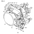
- Fig. 2 is a perspective view showing a schematic structure of the lamp unit.
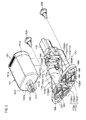
- Fig. 3 is an exploded perspective view showing the lamp unit.
- a vehicular lamp 1 which will be described in this embodiment is a vehicular headlamp device having a pair of headlamp units which are arranged on the right and right of the front of a vehicle. Since the pair of headlamp units has the same configuration except having a bilaterally symmetric structure, Fig. 1 shows, as the vehicle lamp 1, a structure of the headlamp unit which is disposed on the right side of the vehicle.
- the vehicular lamp 1 includes a lamp body 2 having an opening on a front side of a vehicle and a light transmissive cover 4 mounted to cover the opening of the lamp body 2.
- the light transmissive cover 4 is formed of a resin, a glass or the like, having a light transmission property.
- a lamp unit 10 and a control part 12 are accommodated in a lamp chamber 3 which is defined by the lamp body 2 and the light transmissive cover 4.
- a swivel shaft 14 serving as a swinging center of the lamp unit 10 projects at an upper part of the lamp unit 10.
- the swivel shaft 14 is mounted to an upper frame of a bracket 16 which is a substantially rectangular frame body so to be pivotable about an axis.
- the bracket 16 is fixed to the lamp body 2 by a support mechanism (not shown).
- a swivel actuator 18 is provided in a lower part of the bracket 16.
- a pivot output shaft (not shown) protruding upward is provided in the swivel actuator 18.
- the lamp unit 10 is disposed in the frame of the bracket 16, and a lower surface of the lamp unit 10 is connected to the pivot output shaft.
- the swivel actuator 18 is driven in response to a steering operation, for example. Thereby, the lamp unit 10 can be swiveled in the right and left direction about the swivel shaft 14.
- the control part 12 is disposed in a lower part of the lamp chamber 3 and controls turning on/off of the lamp unit 10 and movement of shades (which will be described later), and the like.
- a power supply socket 20 is connected to the control part 12 via a cord 22 and is used to supply power to a light source bulb of the lamp unit 10.
- an installation position of the control part 12 is not particularly limited.
- An extension member 24 is provided in the lamp chamber 3.
- the extension member 24 is disposed on the front side of the lamp unit 10 and fixed to the lamp body 2.
- the extension member 24 forms an opening 24a in an area where the lamp unit 10 exists and covers an area between the front opening of the lamp body 2 and the lamp unit 10, as viewed from the front side of the lamp.
- the lamp unit 10 includes the light source bulb 26, a bulb holding part 28, a reflector part 30, a lens holder 32, a projector lens 34 and an optical unit 100.
- the light source bulb 26 is an incandescent bulb, a halogen lamp, a discharge bulb, or the like.
- the power supply socket 20 is attached to the light source bulb 26. Thereby, power can be supplied from the control part 12 to the light source bulb 26.
- the light source may be a light emitting element.
- the bulb holding part 28 is an annular member and is formed with a cylindrical bulb insertion opening (not shown) whose central axis coincides with an optical axis of the lamp unit 10.
- the reflector part 30 has a reflective surface (not shown) which is configured by a portion of an ellipsoid of revolution. Further, the reflector part 30 is provided at its rear center with a cylindrical bulb insertion opening (not shown) whose central axis coincides with the optical axis of the lamp unit 10.
- a flange portion 30a is provided at a peripheral edge of a front opening 31 of the reflector part 30. The flange portion 30a has a major surface facing the front of the lamp and a major surface facing the rear of the lamp.
- a plurality of positioning protrusion parts 30b are provided to protrude toward the front side of the lamp. Further, a plurality of through-holes 30c passing through the flange portion 30a in a front-and-back direction of the lamp are formed at predetermined positions on the flange portion 30a. Further, the swivel shaft 14 is provided in an upper part of the flange portion 30a.
- the bulb holding part 28 is disposed in such a way that a center axis of the bulb insertion opening of the bulb holding part 28 and a center axis of the bulb insertion opening of the reflector part 30 are located on the same straight line, and is fixed to an inlet of the bulb insertion opening of the reflector part 30.
- the bulb holding part 28 and the reflector part 30 are integrally formed in this embodiment, the bulb holding part and the reflector part may be formed separately.
- the light source bulb 26 is inserted through the bulb insertion opening of the bulb holding part 28 and the bulb insertion opening of the reflector part 30 from the rear of the lamp and is removably mounted to the reflector part 30. By the bulb holding part 28, the light source bulb 26 is fixed to a position where a light emitting part of the light source bulb substantially coincides with a first focal point of the reflective surface of the reflector part 30.
- the lens holder 32 is disposed on a front side of the reflector part 30 across the optical unit 100.
- the lens holder 32 includes a cylindrical part 32a and a plurality of legs 32b protruding from the cylindrical part 32a toward the rear side of the lamp.
- Each leg 32b has a connection part 32b1 which is formed by folding a leading end of each leg 32b substantially at a right angle.
- Each connection part 32b1 is formed with a through-hole 32c penetrating in a front-and-back direction of the lamp.
- the projector lens 34 is fitted to the cylindrical part 32a.
- the projector lens 34 includes a plano-convex aspherical lens having a convex front surface and a flat rear surface.
- the projector lens 34 projects a light source image formed on a rear focal plane including a rear focal point onto a virtual vertical screen in the front of the lamp as an inverted image.
- the lens holder 32 holds the projector lens 34 at a position on an optical axis of the lamp unit 10, where the rear focal point substantially coincides with a second focal point of the reflective surface of the reflector part 30.
- the optical unit 100 includes a substantially plate-shaped base part 110 whose major surfaces face the front-and-back direction of the lamp.
- the base part 110 includes a frame part 112 which has an annular shape as viewed from the front side of the lamp and a shade connecting part 114 which extends in a substantially horizontal direction inside the frame part 112. Further, the base part 110 is formed with an opening 116 which is defined by an upper edge of the shade connecting part 114 and an inner peripheral edge of the frame part 112 above the shade connecting part 114. The opening 116 permits the light from the light source to enter the projector lens 34.
- a plurality of through-holes 118 penetrating in the front-and-back direction of the lamp are formed at predetermined positions of the frame part 112.
- a first shade 130 and a second shade 140 are connected to the shade connecting part 114.
- the first shade 130 and the second shade 140 are provided to be independently swingable relative to the shade connecting part 114.
- Each of the first shade 130 and the second shade 140 is movable between a position where each of the first shade 130 and the second shade 140 blocks a portion of the peripheral edge of the opening 116 and a position where each of the first shade 130 and the second shade 140 extend outside the peripheral edge of the opening 116.
- the optical unit 100 is disposed in such a way that an upper edge of each shade is overlapped with the second focal point of the reflective surface of the reflector part 30 when each shade is moved to the position where each shade blocks the portion of the peripheral edge of the opening 116.
- the structure of the optical unit 100 will be described in detail later.
- each positioning protrusion part 30b is inserted through the predetermined through-hole 118, a positional relationship between the reflector part 30 and the optical unit 100 is determined. Further, when the predetermined positioning protrusion part 30b protruding from the through-hole 118 of the optical unit 100 is inserted through the predetermined through-hole 32c, a positional relationship of the lens holder 32 relative to the reflector part 30 and the optical unit 100 is determined. In this state, the predetermined through-hole 30c of the reflector part 30, the predetermined through-hole 118 of the optical unit 100 and the predetermined through-hole 32c of the lens holder 32 are overlapped, as viewed from the front side of the lamp. Then, when a fastening member 36 such as a screw is inserted through these through-holes 30c, 118 and 32c, the reflector part 30, the optical unit 100 and the lens holder 32 are connected to each other.
- a fastening member 36 such as a screw
- Fig. 4 is an exploded perspective view showing the optical unit 100 according to the exemplary embodiment.
- the optical unit 100 according to this embodiment is an optical unit for use in a vehicular lamp and includes the base part 110, the first shade 130, the second shade 140, a first motor 150A, a second motor 150B, a first casing 170A and a second casing 170B.
- first motor 150A and the second motor 150B are particularly distinguished from each other, these motors 150A, 150B are collectively referred to a "motor 150.”
- first casing 170A and the second casing 170B are particularly distinguished from each other, these casings 170A, 170B are collectively referred to a "casing 170.”
- the base part 110 includes the frame part 112, the shade connecting part 114, the opening 116 and the through-holes 118, as described above.
- the base part 110 includes a first shade support shaft 120A at a right-side end (an inside end in the vehicle width direction) of the shade connecting part 114 and a second shade support shaft 120B at a left-side end (an outside end in the vehicle width direction) of the shade connecting part 114, as viewed from the front side of the lamp.
- the first shade support shaft 120A protrudes toward the front side of the lamp
- the second shade support shaft 120B protrudes toward the front side of the lamp.
- the base part 110 includes a plurality of casing fixing through-holes 121A, a plurality of fitted parts 122A and a through-hole 123A for an output shaft in a right-side area of the frame part 112 and a plurality of casing fixing through-holes 121B, a plurality of fitted parts 122B and a through-hole 123B for the output shaft in a left-side area of the frame part 112, as viewed from the front side of the lamp.
- the fitted parts 122A, 122B are through-holes.
- the base part 110 includes a first stopper 124A for the first shade and a first stopper 124B for the second shade in an area on an inner peripheral edge side of the frame part 112. Also, the base part 110 includes a second stopper 125A for the first shade and a second stopper 125B for the second shade in an area on an outer peripheral edge side of the frame part 112. As viewed from the front side of the lamp, the first stopper 124A for the first shade and the second stopper 125A for the first shade are disposed in a right-side area of the base part 110, and the first stopper 124B for the second shade and the second stopper 125B for the second shade are disposed in a left-side area of the base part 110.
- the base part 110 includes a return-spring locking hole 126 and a return-spring locking hole 127 at predetermined positions on the frame part 112 (see Figs. 9A, 9B and 10B ).
- the first and second shades 130, 140 have a substantially L-shaped structure and include horizontal parts 132, 142 and vertical parts 134, 144, respectively.
- the horizontal parts 132, 142 extend in the substantially horizontal direction and are used to block the light from the light source.
- the vertical parts 134, 144 extend substantially vertically downward from one end of the horizontal parts 132, 142 and are subjected to rotation forces of the motors 150.
- An edge 132a of the horizontal part 132 of the first shade 130 is processed to form a cut-off line of a low-beam light distribution pattern when the first shade 130 is in an advanced position (which will be described later).
- An edge 142a of the horizontal part 142 of the second shade 140 is processed to form a cut-off line of one-side high light distribution pattern when the second shade 140 is in the advanced position (which will be described later).
- Gear parts 135, 145 are provided at lower ends of the vertical parts 134, 144 and meshed with connecting parts (which will be described later) provided in output shafts of the motors 150.
- the first and second shades 130, 140 respectively include cylindrical parts 136, 146 protruding toward the front side of the lamp and being in the vicinity of joined parts between the horizontal parts 132, 142 and the vertical parts 134, 144. Further, the first and second shades 130, 140 respectively include return-spring locking grooves 138, 148 at predetermined positions.
- the first shade 130 is held in the base part 110 by inserting the first shade support shaft 120A into the cylindrical part 136. Thereby, the first shade 130 is disposed on the inner side in the vehicle width direction.
- the horizontal part 132 extends toward the second shade support shaft 120B.
- the vertical part 134 extends between the first stopper 124A for the first shade and the second stopper 125A for the first shade.
- the gear part 135 of the vertical part 134 is disposed in the vicinity of the through-hole 123A for the output shaft.
- the second shade 140 is held in the base part 110 by inserting the second shade support shaft 120B into the cylindrical part 146. Thereby, the second shade 140 is disposed on the outer side in the vehicle width direction.
- the horizontal part 142 extends toward the first shade support shaft 120A.
- the vertical part 144 extends between the first stopper 124B for the second shade and the second stopper 125B for the second shade.
- the gear part 145 of the vertical part 144 is disposed in the vicinity of the through-hole 123B for the output shaft.
- Retaining rings 102 and return springs 104A, 104B are fitted in this order to an outer periphery of the cylindrical parts 136, 146, respectively.
- the return springs 104A, 104B are implemented by a torsion coil spring, for example, and include coil portions whose both ends extend in an arm shape.
- one end of the return spring 104A is inserted into the return-spring locking hole 126, and the other end thereof is locked by the return-spring locking hole 138.
- one end of the return spring 104B is inserted into the return-spring locking hole 127, and the other end thereof is locked by the return-spring locking hole 148.
- Fig. 5 is a perspective view showing a schematic structure of the motor 150 and the casing 170.
- Fig. 6 is a schematic section view of the motor 150 and the casing 170.
- Figs. 7A and 7B are perspective views for explaining the connection between the motor 150 and power supply terminals.
- Fig. 6 shows a state where the motor 150 is accommodated in the casing 170.
- Fig. 6 is a section view taken along the output shaft 152 of the motor 150.
- the motor 150 is implemented by a DC motor, for example, and includes a housing 151, the output shaft 152, and terminal connection parts 153A, 153B.
- the housing 151 has an upper surface 151a, a bottom surface 151b opposed to the upper surface 151a, a first side surface 151c and a second side surface 151d which are substantially planar and are opposed to each other, and a third side surface 151e and a fourth side surface 151f which are curved and are opposed to each other.
- the output shaft 152 protrudes from the upper surface 151a.
- the upper surface 151a and the bottom surface 151b are respectively provided with boss parts 154a, 154b which protrude slightly outward therefrom. Each of the boss parts 154a, 154b is adapted to contain a bearing therein.
- the output shaft 152 is provided with a connection part 160 which is configured by a gear such as a spur gear.
- the output shaft 152 is connected to the first shade 130 or the second shade 140 via the connection part 160.
- the terminal connection parts 153A, 153B for the power supply are provided in the vicinity of the bottom surface 151b in the first side surface 151c of the housing 151.
- the terminal connection part 153A corresponds to one of an anode and a cathode
- the terminal connection part 153B corresponds to the other of the anode and the cathode.
- the casing 170 includes a wall part 172, an accommodation space 174, an opening part 176, a connector 178, the power supply terminals 180A, 180B, and wiring parts 182A, 182B.
- the wall part 172 has a substantially rectangular bottom wall part 172a, a first wall part 172b, a second wall part 172c, a third wall part 172d and a fourth wall part 172e.
- the first wall part 172b and the fourth wall part 172e are opposed to each other.
- the second wall part 172c and the third wall part 172d are opposed to each other and extend substantially perpendicular to the first wall part 172b and the fourth wall part 172e.
- a side wall part is configured by the first wall part 172b, the second wall part 172c, the third wall part 172d and the fourth wall part 172e. These four side wall parts and the bottom wall part 172 define the accommodation space 174 for accommodating the motor 150. Lower ends of these four side wall parts 172b, 172c, 172d, 172e are connected to a peripheral edge of the bottom wall part 172a, but no wall part is provided on an upper end side of these side wall parts 172b, 172c, 172d, 172e. That is, the opening part 176 that enables the motor 150 to be inserted into the accommodation space 174 therethrough is formed on the upper end side of the four side wall parts 172b, 172c, 172d, 172e.
- the connector 178 includes an insertion opening 178m into which a terminal of an external power source is inserted and connector terminals 178A, 178B disposed in the insertion opening 178m.
- the connector 178 is provided on an outer surface of the fourth wall part 172e.
- the power supply terminals 180A, 180B are exposed in the accommodation space 174.
- One end of the wiring part 182A is connected to the connector terminal 178A, the wiring part 182A is wired from the connector 178 to the accommodation space 174, and the other end of the wiring part 182A is connected to the power supply terminal 180A.
- One end of the wiring part 182B is connected to the connector terminal 178B, the wiring part 182B is wired from the connector 178 to the accommodation space 174, and the other end of the wiring part 182B is connected to the power supply terminal 180B.
- the power supply terminals 180A, 180B are electrically connected to the connector 178.
- the terminal of the external power source is inserted into the insertion opening 178a and connected to the connector terminals 178A, 178B in the insertion opening 178a.
- the connector 178 is connected to the external power source (see Fig. 1 ).
- power fed from the external power source is supplied to the motor 150 via the connector terminals 178A, 178B, the wiring parts 182A, 182B, and the power supply terminals 180A, 180B.
- the motor 150 is disposed in such a manner that the first side surface 151c thereof faces the bottom wall part 172a. Therefore, the opening part 176 is disposed substantially parallel to an axial direction of the output shaft 152.
- the motor 150 is pressed in a direction which is substantially perpendicular to the axial direction of the output shaft 152 and in which the first side surface 151 and the bottom wall part 172a approach each other. In this way, the motor 150 is inserted into the accommodation space 174 through the opening part 176.
- the upper surface 151a and the first wall part 172b face each other
- the bottom surface 151b and the fourth wall part 172e face each other
- the first side surface 151c and the bottom wall part 172a face each other
- the third side surface 151e and the second wall part 172c face each other
- the fourth side surface 151f and the third wall part 172d face each other.
- the power supply terminals 180A, 180B are provided in such a manner that the terminal connection parts 153A, 153B and the power supply terminals 180A, 180B are brought into physical contact with each other when the motor 150 is inserted into the accommodation space 174.
- the terminal connection parts 153A, 153B are provided in the vicinity of the bottom surface 151b in the first side surface 151c.
- the power supply terminals 180A, 180B project in the vicinity of the fourth wall part 172e in the bottom wall part 172a, which faces the first side surface 151c in the state where the motor 150 is accommodated in the accommodation space 174.
- the motor 150 when the motor 150 is inserted into the casing 170, the motor 150 is accommodated in the casing 170 and at the same time the power supply terminals 180A, 180B are inserted into the terminal connection parts 153A, 153B. Therefore, with the optical unit 100 of this embodiment, since the accommodation of the motor 150 in the casing 170 and the electric connection between the motor 150 and the connector 178 can be simultaneously carried out, it is possible to simplify the manufacturing process of the optical unit 100.
- the fourth wall part 172e of the casing 170 is provided with a slit 172e1 into which the boss part 154b of the motor 150 is inserted. Further, a fixing hook part 184 protruding toward the slit 172e1 is provided between the fourth wall part 172e and the connector 178. As the motor 150 is inserted into the casing 170, the fixing hook part 184 is pressed and elastically deformed by the boss part 154b of the motor 150 and thus displaced toward the outside of the slit 172e1. The fixing hook part 184 gets over the boss part 154b when the motor 150 is completely accommodated in the casing 170.
- first wall part 172b being in contact with the opening part 176 is divided into a first portion 172b2 and a second portion 172b3 by a slit 172b1 extending from the opening part 176.
- a boss receiving part 172b4 protruding from the bottom wall part 172a side is provided in the slit 172b1.
- the boss receiving part 172b4 constitutes a portion of the first wall part 172b.
- protruding parts 172b5, 172b6 protruding toward the slit 172b1 are provided in respective surfaces, being in contact with the slit 172b1, of the first portion 172b2 and the second portion 172b3.
- a narrow part having a slit width smaller than the other area is formed in the slit 172b1.
- the slit width in the narrow part is smaller than a diameter of the boss part 154a.
- the first wall part 172b is deformed by the boss part 154a of the motor 150, which enables the motor 150 to enter the casing 170.
- the output shaft 152 protrudes to the outside from the accommodation space 174 via the slit 172b1.
- Figs. 8A to 8C are views for explaining a change in shape of the first wall part 172b when the motor 150 is accommodated into the casing 170.
- the boss part 154a enters the slit 172b1 through an open end of the slit 172b1. Then, the boss part 154a is pushed toward the narrow part of the slit 172b1 formed by the protruding parts 172b5, 172b6 (see Fig. 5 ).
- the protruding parts 172b5, 172b6 are pressed by the boss part 154a in a direction in which the slit width of the narrow part is enlarged.
- the first wall part 172b is elastically deformed and therefore, the first portion 172b2 and the second portion 172b3 are displaced in directions (directions indicated by arrows in Fig. 8B ) so as to be away from each other.
- the motor 150 can be enter the accommodation space 174 (see Fig. 5 ).
- the motor 150 is fixed to the casing 170 by so-called snap-fitting. Therefore, it is possible to simplify the manufacturing process of the optical unit 100. Further, since it is not necessary to provide a cover configured to close the opening part 176 in order to prevent detachment of the motor 150 from the casing 170, it is possible to realize reduction in cost and weight by reducing the number of parts of the optical unit 100.
- the first portion 172b2 of the first wall part 172b includes a first flange portion 186 protruding in a surface direction of the first wall part 172b
- the second portion 172b3 includes a second flange portion 187 protruding in the surface direction of the first wall part 172b.
- the first flange portion 186 and the second flange portion 187 are respectively provided with fixing mechanisms 188 configured to fix the casing 170 to the base part 110.
- the fixing mechanisms 188 are insertion holes into which fastening members such as screws are inserted, respectively.
- first portion 172b2 and the second portion 172b3 respectively include positioning protrusion parts 189.
- the positioning protrusion parts 189 are provided on surfaces of the first portion 172b and the second portion 172c which are in contact with the base part 110 in the state where the casing 170 is fixed to the base part 110.
- the positioning protrusion parts 189 protrude substantially parallel to the axial direction of the output shaft 152.
- the casing 170 is mounted to the base part 110 in such a manner that the first wall part 172b is brought into contact with the major surface, on the rear side of the lamp, of the frame part 112 of the base part 110. Accordingly, the motor 150 is disposed in such a manner that the output shaft 152 is substantially perpendicular to the surface, being in contact with the casing 170, of the base part 110.
- the fixing mechanism 188 that is a through-hole is positioned to the casing fixing through-hole 121A of the base part 110, and the first casing 170A is mounted to the base part 110.
- the output shaft 152 of the first motor 150A and the connection part 160 are inserted through the through-hole 123A for the output shaft in the base part 110, and the teeth of the connection part 160 that is the gear is meshed with the gear part 135 of the first shade 130 (see Fig. 3 ).
- the positioning protrusion part 189 is fitted into the fitted part 122A of the base part 110 and therefore, the first casing 170A is positioned with respect to the base part 110 with high-accuracy.
- the first casing 170A is fixed to the base part 110 by inserting the fastening members 200 such as screws through the fixing mechanisms 188 of the first casing 170A and the casing fixing through-holes 121A of the base part 110.
- the fixing mechanism 188 that is a through-hole is positioned to the casing fixing through-hole 121B of the base part 110, and the second casing 170B is mounted to the base part 110.
- the output shaft 152 of the second motor 150B and the connection part 160 are inserted through the through-hole 123B for the output shaft in the base part 110, and the teeth of the connection part 160 that is a gear is meshed with the gear part 145 of the second shade 140 (see Fig. 3 ).
- the positioning protrusion part 189 is fitted into the fitted part 122B of the base part 110 and therefore, the positioning of the second casing 170B to the base part 110 is realized with high-accuracy.
- the second casing 170B is fixed to the base part 110 by inserting the fastening members 200 such as screws through the fixing mechanisms 188 of the second casing 170B and the casing fixing through-holes 121B of the base part 110.
- the casing 170 includes the fixing mechanism 188 at the first flange portion 186 of the first portion 172b2 and the fixing mechanism 188 at the second flange portion 187 of the second portion 172b3.
- the first portion 172b2 and the second portion 172b3 are fixed to the base part 110. Therefore, in a state where the casing 170 is fixed to the base part 110, the displacement of the first portion 172b2 and the second portion 172b3 in a direction away from each other is suppressed. Accordingly, it is possible to prevent the motor 150 from being detached from the casing 170, by using an attachment mechanism of the casing 170 to the base part 110.
- the positioning protrusion parts 189 are also provided in the first portion 172b2 and the second portion 172b3, it is possible to further prevent the first portion 172b2 and the second portion 172b3 from being displaced in the direction away from each other, by the positioning protrusion parts 189. Accordingly, it is possible to prevent the motor 150 from being detached from the casing 170, by using the positioning mechanism of the casing 170 to the base part 110.
- the positioning of the casing 170 to the base part 110 may be accurately carried out by the casing fixing through-holes 121A, 121B, the fixing mechanisms 188, and the fastening members 200.
- the positioning protrusion parts 189 may be omitted.
- the casing 170 is fixed to the base part 110 by using the fastening members 200, while the casing fixing through-holes 121A and the fixing mechanisms 188 are through-holes in this embodiment.
- any of other fixing methods known in a related art may be used.
- FIGs. 9A to 9C are views for explaining the states of the first shade 130 and the second shade 140 and the light distribution patterns to be formed.
- Figs. 9A to 9C show the optical unit 100 as viewed from the front side of the lamp.
- the first shade 130 and the second shade 140 are respectively movable between advanced positions where a portion of light from a light source is blocked and retreated positions where the part of the light from the light source is not blocked, with the first shade support shaft 120A and the second shade support shaft 120B being pivot axes.
- Each shade 130, 140 is moved from one to the other of the advanced position and the retreated position by the rotation of the output shaft 152 of the motor 150. Further, each shade 130, 140 is moved from the other to the one of the advanced position and the retreated position by a biasing force of the return springs 104A, 104B when the motor 150 is turned off.
- a force from the output shaft 152 of the first motor 150A is transmitted to the first shade 130 via the connection part 160 and thus, the first shade 130 is moved from the advanced position to the retreated position by the rotation of the output shaft 152.
- the first shade 130 being moved toward the retreated position abuts against the second stopper 125A for the first shade and is stopped at the retreated position.
- the first shade 130 is moved from the retreated position to the advanced position by the biasing force of the return spring 104A when the first motor 150A is turned off.
- the first shade 130 being moved toward the advanced position abuts against the first stopper 124A for the first shade and is stopped at the advanced position.
- the first shade 130 for forming the low-beam light distribution pattern is returned to the advanced position by the return spring 104A.
- the optical unit 100 is reliably prevented from being fixed in a posture to form the high-beam light distribution pattern or one-side high light distribution pattern and therefore, it is possible to realize a fail-safe function.
- the rotation of the output shaft 152 of the second motor 150B is transmitted to the second shade 140 via the connection part 160 and thus, the second shade is moved from the retreated position to the advanced position by the rotation of the output shaft 152.
- the second shade 140 being moved toward the advancing position abuts against the first stopper 124B for the second shade and is stopped at the advanced position.
- the second shade 140 is moved from the advanced position to the retreated position by a biasing force of the return spring 104B when the second motor 150B is turned off.
- the second shade 140 being moved toward the retreated position abuts against the second stopper 125B for the second shade and is stopped at the retreated position.
- the lamp unit 10 in a state where the first shade 130 is in the advanced position and the second shade 140 is in the retreated position, the lamp unit 10 can form the low-beam light distribution pattern. Also, as shown in Fig. 9B , in a state where the first shade 130 and the second shade 140 are in the retreated positions, the lamp unit 10 can form the high-beam light distribution pattern. Furthermore, as shown in Fig. 9C , in a state where the first shade 130 is in the retreated position and the second shade 140 is in the advanced position, the lamp unit 10 can form a so-called right-side high light distribution pattern having a high-beam area only on the oncoming-vehicle-lane side during the left-hand traffic.
- the first shade 130 is disposed on a left side (inside in the vehicle width direction) and the second shade 140 is disposed on a right side (outside in the vehicle width direction), as viewed from the front side of the lamp.
- the lamp unit can form the low-beam light distribution pattern, the high-beam light distribution pattern, and a so-called left-side high light distribution pattern having a high-beam area only on the own-vehicle-lane side during the left-hand traffic.
- the shapes of the respective light distribution patterns described above are known and therefore, detailed description thereon will be omitted.
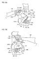
- Fig. 10A is an enlarged view showing the vicinity of the gear part 135 of the first shade 130.
- Fig. 10B is an enlarged view showing the vicinity of the gear part 145 of the second shade 140.
- Fig. 11 is a view showing a schematic structure of the optical unit 100 as viewed from the rear side of the lamp.
- the first shade 130 is moved from the advanced position toward the retreated position against the biasing force of the return spring 104A when the output shaft 152 of the first motor 150A is rotated in a direction of an arrow S.
- the first shade 130 abuts against the second stopper 125A for the first shade and is stopped at the retreated position. Even after the first shade 130 is stopped at the retreated position, the rotation force of the output shaft 152 of the first motor 150A is transmitted to the first shade 130 and therefore, the first shade 130 is continuously pressed by the connection part 160, so that the first shade 130 is held in the retreated position.
- the first motor 150A is subjected to a reaction force of the force F1 and tries to move or displace in a direction X1 (a direction substantially perpendicular to a straight line connecting the contact point T and the output shaft 152), that is substantially opposite to a direction in which the vertical part 134 of the first shade 130 is biased, with the contact point T being a support point.
- the second shade 140 is moved from the retreated position toward the advanced position against the biasing force of the return spring 104B when the output shaft 152 of the second motor 150B is rotated in the direction of the arrow S. Then, the second shade 140 abuts against the first stopper 124B for the second shade and is stopped at the advanced position. Even after the second shade 140 is stopped at the advanced position, the rotation force of the output shaft 152 of the second motor 150B is transmitted to the second shade 140 and therefore, the second shade 140 is continuously pressed by the connection part 160, so that the second shade 140 is held in the advanced position.
- a force F1 in a direction to press the second shade 140 against the first stopper 124B for the second shade is continuously applied to a contact point T between the connection part 160 and the gear part 145.
- the movement of the second shade 140 is restricted by the first stopper 124B for the second shade. Therefore, the second motor 150B is subjected to a reaction force of the force F1 and tries to move or displace in a direction X2 (a direction substantially perpendicular to a straight line connecting the contact point T and the output shaft 152), that is substantially opposite to a direction in which the vertical part 144 of the second shade 140 is biased, with the contact point T being a support point.
- the posture of the casing 170 is with respect to the base part 110 is determined so that at least a portion of the wall part 172 exists on a leading end side in the directions X1, X2 in which the motor 150 is displaced by the force, which is applied to the motor 150 as the shade in contact with the stopper is continuously pressed by the connection part 160, and the casing 170 is fixed to the base part 110.
- the first motor 150A since the first shade 130 in contact with the second stopper 125A for the first shade is continuously pressed, the first motor 150A tries to move or displace in the lower-right direction X1, as viewed from the rear side of the lamp.
- the bottom wall part 172a of the first casing 170A exists on the leading end side in the displacement direction X1 of the first motor 150A.
- the second motor 150B tries to move or displace in the substantially upper right direction X2, as viewed from the rear side of the lamp.
- the bottom wall part 172a of the second casing 170B exists on the leading end side in the displacement direction X2 of the second motor 150B.
- the displacement of the motor 150 can be restricted by the wall part 172 of the casing 170, it is possible to reliably prevent the motor 150 from being detached from the casing 170. Accordingly, according to the optical unit 100 of this embodiment, the prescribed mounting posture of the motor can be maintained and thus, it is possible to improve operation reliability of the optical unit 100.
- Fig. 12A is an exploded perspective view showing a schematic structure of the motor 150.
- Fig. 12B is a schematic view showing the internal structure of the motor 150.
- the motor 150 includes a commutator 155, a pair of brushes 156, a pair of brush arms 157, a core 158, a winding 159 and a plurality of magnets 162, in addition to the housing 151, the output shaft 152 and the terminal connection parts 153A, 153 (see Fig. 7A ) described above.
- the commutator 155 has a cylindrical shape and press-fitted to the output shaft 152. Therefore, the commutator 155 is rotated together with the output shaft 152.
- the commutator 155 includes a plurality of commutator segments 155a that are arranged at intervals around an axis of the output shaft 152. In this embodiment, three commutator segments 155a are provided.
- the pair of brushes 156 are provided across the commutator 155.
- the two brushes 156 are respectively mounted to leading ends of the brush arms 157, and are held so that leading end surfaces thereof are in sliding contact with an outer peripheral surface of the commutator 155.
- One of the two brush arms 157 is connected to the terminal connection part 153A, and the other thereof is connected to the terminal connection part 153B.
- the core 158 on which the winding 159 is wound is press-fitted to the output shaft 152.
- the plurality of magnets 162 are provided along an inner surface of the housing 151 and arranged at intervals in a circumferential direction.
- the core 158 is arranged so that an outer peripheral surface thereof faces inner peripheral surfaces of the magnets 162 with a predetermined clearance therebetween.
- the structure of the motor 150 is known in a related art and thus, further detailed description thereon will be omitted.
- the advanced positions and the retreated positions of the first shade 130 and the second shade 140 are set so that a rotation angle ⁇ of the output shaft 152 when the shades are moved by the motor 150 satisfies the following formula (1).
- ⁇ ⁇ 360 ⁇ ° / n where n denotes the number of the commutator segments.
- a positional relationship between the first stopper 124A for the first shade and the second stopper 125A for the first shade and a positional relationship between the first stopper 124B for the second shade and the second stopper 125B for the second shade are respectively established so that the rotation angle ⁇ satisfies the above formula (1).
- the rotation angle ⁇ of the output shaft 152 satisfies the above formula (1)
- the rotation angle ⁇ of the output shaft 152 during the movement of the shades is equal to or greater than an angular interval at which the gaps 155b are arranged. Therefore, it is possible to reliably allow the brush 156 to pass over the gap 155b between the commutator segments 155a.
- the motor 150 includes the three commutator segments 155a, which are arranged at regular intervals around the axis of the output shaft 152. Therefore, the gaps 155b are arranged at intervals of approximately 120°. Then, the advanced position and the retreated position are set so that the rotation angle ⁇ of the output shaft 152 during the movement of the shades is equal to or greater than 120°. Therefore, the brushes 156 surely straddle the gaps 155b during the movement of the shades.
- the advanced positions and the retreated positions of the first shade 130 and the second shade 140 are set so that the rotation angles ⁇ of the output shafts 152 satisfy the above formula (1) when the first shade 130 and the second shade 140 are moved from the advanced position to the retreated position or from the retreated position to the advanced position.
- the motor 150 can be normally worked for a longer time and therefore, it is possible to improve the operation reliability of the optical unit 100.
- the posture of the casing 170 with respect to the base part 110 is determined so that at least a portion of the wall part 172 exists on the leading end side in the directions in which the motor 150 is displaced by a force applied to the motor 150 as the shade in contact with the stopper is continuously pressed by the connection part 160.
- the power supply terminals 180A, 180B are disposed in the accommodation space 174 so that the terminal connection parts 153A, 153B and the power supply terminals 180A, 180B are brought into physical contact with each other when the motor 150 is inserted into the accommodation space 174.
Landscapes
- Engineering & Computer Science (AREA)
- General Engineering & Computer Science (AREA)
- Non-Portable Lighting Devices Or Systems Thereof (AREA)
- Lighting Device Outwards From Vehicle And Optical Signal (AREA)
Abstract

Description
- The invention relates generally to an optical unit and, more particularly, to an optical unit for use in a vehicular lamp.
- In a related art, there has been a light distribution variable type vehicular headlamp device which forms a low-beam light distribution pattern when light from a light source is blocked with a shade and a high-beam light distribution pattern when the light is not blocked with the shade. Further, with the advance in performance of vehicles in recent years, such a vehicular headlamp device has been suggested that is forms a special light distribution pattern different from the shape of the standard low-beam or that of the standard high-beam in accordance with the surrounding conditions. Particularly, with regard to the high-beam, it is necessary to consider glare which causes to oncoming vehicles and/or pedestrians while improving the visibility of a driver. Therefore, for example, a vehicular lamp described in
JP 2007-179969 A US 2007/0147055 A1 ) has a structure which can optimally set an illumination area of high-beam in accordance with presence or absence of pedestrians, preceding vehicles and/or oncoming vehicles. - In such a situation, the inventor came to recognize the following issues. That is, as an optical unit to implement the switching between the above-described light distribution patterns in a vehicular lamp, for example, such a configuration may be conceived that a plurality of shades are provided each of which is movable between an advanced position where a portion of light from a light source is blocked and a retreated position where the portion of the light from the light source is not blocked and that the light distribution pattern is switched by switching the position of each shade. Specifically, for example, a low-beam light distribution pattern is formed by placing a first shade in a blocking position, a special light distribution pattern is formed by placing a second shade in the blocking position and placing the first shade in a non-blocking position, and a high-beam light distribution pattern is formed by placing both the first shade and the second shade in the non-blocking positions. A motor such as DC motor may be used to move the shades.
- It is always demanded to simplify the manufacturing process of a vehicular lamp. Therefore, the optical unit having the configuration described above is also required to simplify its manufacturing process.
- The invention has been made in view of the above circumstances and provides a technique to simplify the manufacturing process of an optical unit.
- In order to solve the above object, one embodiment of the invention relates to an optical unit. The optical unit includes a shade, a motor, and a casing. The shade is movable between an advanced position a retreated position. The motor includes terminal connection parts for power supply, and an output shaft connected to the shade. The motor moves the shade from one of the advanced position and the retreated position to the other by rotation of the output shaft. The casing includes wall parts, an opening part, a connector, and power supply terminals. The wall parts forms an accommodation space for the motor. The opening part is used to insert the motor into the accommodation space therethrough. The connector is to be connected to an external power source. The power supply terminals are electrically connected to the connector and exposed to the accommodation space. The power supply terminals are disposed in the accommodation space so that the terminal connection parts and the power supply terminals are brought into physical contact with each other when the motor is inserted into the accommodation space.
- With this embodiment, since the accommodation of the motor into the case and the electric connection between the motor and the connector can be simultaneously carried out, it is possible to simplify the manufacturing process of the optical unit.
- In the above embodiment, the wall parts may include a first wall part that is in contact with the opening part. The first wall part may be divided into a first portion and a second portion by a slit extending from the opening part. The casing may be configured such that the motor is entering the accommodation space with the first portion and the second portion displacing in directions to be away from each other. When the motor is accommodated in the accommodation space, it may be suppressed by displacing the first portion and the second portion in directions so as to approach each other that the motor is detached from the accommodation space. Thereby, it is possible to further simplify the manufacturing process of the optical unit.
- In the above embodiment, the optical unit may further include a base part that holds the shade. The first wall part may abut against the base part (110). The first portion may include a first flange portion (186) protruding in a surface direction of the first wall part. The second portion may include a second flange portion protruding in the surface direction of the first wall part. The first flange portion and the second flange portion may be respectively provided with fixing mechanisms configured to fix the casing to the base part. Thereby, it is possible to prevent the motor from being detached from the case by using an attachment mechanism of the case to the base part.
- In the above embodiment, the optical unit may further include a base part that holds the shade. The first wall part may abut against the base part. Each of the first portion and the second portion may include a positioning protrusion part on a surface thereof being in contact with the base part. The base part may include fitted parts into which the positioning protrusion parts are fitted. Thereby, it is possible to prevent the motor from being detached from the case by using a positioning mechanism of the case to the base part.
- According to the invention, it is possible to provide a technique to simplify the manufacturing process of an optical unit.
-
-
Fig. 1 is a vertical section view showing a schematic structure of a vehicular lamp on which a lamp unit having an optical unit according to one embodiment is mounted. -
Fig. 2 is a perspective view showing a schematic structure of the lamp unit. -
Fig. 3 is an exploded perspective view showing the lamp unit. -
Fig. 4 is an exploded perspective view showing the optical unit according to the embodiment. -
Fig. 5 is a perspective view showing a schematic structure of a motor and a casing. -
Fig. 6 is a schematic section view of the motor and the casing. -
Figs. 7A and 7B are perspective views for explaining connection between the motor and power supply terminals. -
Figs. 8A to 8C are views for explaining a change in shape of a first wall part when the motor is accommodated into the casing. -
Figs. 9A to 9C are views for explaining states of the first shade and the second shade and formed light distribution patterns. -
Fig. 10A is an enlarged view showing the vicinity of a gear part of the first shade. -
Fig. 10B is an enlarged view showing the vicinity of a gear part of the second shade. -
Fig. 11 is a view showing a schematic structure of the optical unit as viewed from the rear side of the lamp. -
Fig. 12A is an exploded perspective view showing a schematic structure of the motor. -
Fig. 12B is a schematic view showing the internal structure of the motor. - Hereinafter, exemplary embodiments of the invention will be described in detail with reference to the accompanying drawings. The same or similar reference numerals are assigned to the same or similar parts, elements and process throughout the drawings. Duplicate description thereon will be omitted. Further, the embodiments described blow are illustrative and are not intended to limit the invention. It should be noted that all features described in the embodiments and their combinations does not always constitute an essential part of the invention.
-
Fig. 1 is a vertical section view showing a schematic structure of a vehicular lamp on which a lamp unit having an optical unit according to an exemplary embodiment is mounted.Fig. 2 is a perspective view showing a schematic structure of the lamp unit.Fig. 3 is an exploded perspective view showing the lamp unit. Avehicular lamp 1 which will be described in this embodiment is a vehicular headlamp device having a pair of headlamp units which are arranged on the right and right of the front of a vehicle. Since the pair of headlamp units has the same configuration except having a bilaterally symmetric structure,Fig. 1 shows, as thevehicle lamp 1, a structure of the headlamp unit which is disposed on the right side of the vehicle. - As shown in
Fig. 1 , thevehicular lamp 1 includes alamp body 2 having an opening on a front side of a vehicle and alight transmissive cover 4 mounted to cover the opening of thelamp body 2. Thelight transmissive cover 4 is formed of a resin, a glass or the like, having a light transmission property. Alamp unit 10 and acontrol part 12 are accommodated in alamp chamber 3 which is defined by thelamp body 2 and thelight transmissive cover 4. Aswivel shaft 14 serving as a swinging center of thelamp unit 10 projects at an upper part of thelamp unit 10. Theswivel shaft 14 is mounted to an upper frame of abracket 16 which is a substantially rectangular frame body so to be pivotable about an axis. Thebracket 16 is fixed to thelamp body 2 by a support mechanism (not shown). - A
swivel actuator 18 is provided in a lower part of thebracket 16. A pivot output shaft (not shown) protruding upward is provided in theswivel actuator 18. Thelamp unit 10 is disposed in the frame of thebracket 16, and a lower surface of thelamp unit 10 is connected to the pivot output shaft. Theswivel actuator 18 is driven in response to a steering operation, for example. Thereby, thelamp unit 10 can be swiveled in the right and left direction about theswivel shaft 14. - The
control part 12 is disposed in a lower part of thelamp chamber 3 and controls turning on/off of thelamp unit 10 and movement of shades (which will be described later), and the like. Apower supply socket 20 is connected to thecontrol part 12 via acord 22 and is used to supply power to a light source bulb of thelamp unit 10. Here, an installation position of thecontrol part 12 is not particularly limited. - An
extension member 24 is provided in thelamp chamber 3. Theextension member 24 is disposed on the front side of thelamp unit 10 and fixed to thelamp body 2. Theextension member 24 forms anopening 24a in an area where thelamp unit 10 exists and covers an area between the front opening of thelamp body 2 and thelamp unit 10, as viewed from the front side of the lamp. - As shown in
Figs. 1 to 3 , thelamp unit 10 includes thelight source bulb 26, abulb holding part 28, areflector part 30, alens holder 32, aprojector lens 34 and anoptical unit 100. For example, thelight source bulb 26 is an incandescent bulb, a halogen lamp, a discharge bulb, or the like. Thepower supply socket 20 is attached to thelight source bulb 26. Thereby, power can be supplied from thecontrol part 12 to thelight source bulb 26. Here, the light source may be a light emitting element. - The
bulb holding part 28 is an annular member and is formed with a cylindrical bulb insertion opening (not shown) whose central axis coincides with an optical axis of thelamp unit 10. Thereflector part 30 has a reflective surface (not shown) which is configured by a portion of an ellipsoid of revolution. Further, thereflector part 30 is provided at its rear center with a cylindrical bulb insertion opening (not shown) whose central axis coincides with the optical axis of thelamp unit 10. Aflange portion 30a is provided at a peripheral edge of afront opening 31 of thereflector part 30. Theflange portion 30a has a major surface facing the front of the lamp and a major surface facing the rear of the lamp. At a predetermined position of the major surface of theflange portion 30a on the front side of the lamp, a plurality ofpositioning protrusion parts 30b are provided to protrude toward the front side of the lamp. Further, a plurality of through-holes 30c passing through theflange portion 30a in a front-and-back direction of the lamp are formed at predetermined positions on theflange portion 30a. Further, theswivel shaft 14 is provided in an upper part of theflange portion 30a. - The
bulb holding part 28 is disposed in such a way that a center axis of the bulb insertion opening of thebulb holding part 28 and a center axis of the bulb insertion opening of thereflector part 30 are located on the same straight line, and is fixed to an inlet of the bulb insertion opening of thereflector part 30. Although thebulb holding part 28 and thereflector part 30 are integrally formed in this embodiment, the bulb holding part and the reflector part may be formed separately. Thelight source bulb 26 is inserted through the bulb insertion opening of thebulb holding part 28 and the bulb insertion opening of thereflector part 30 from the rear of the lamp and is removably mounted to thereflector part 30. By thebulb holding part 28, thelight source bulb 26 is fixed to a position where a light emitting part of the light source bulb substantially coincides with a first focal point of the reflective surface of thereflector part 30. - The
lens holder 32 is disposed on a front side of thereflector part 30 across theoptical unit 100. Thelens holder 32 includes acylindrical part 32a and a plurality oflegs 32b protruding from thecylindrical part 32a toward the rear side of the lamp. Eachleg 32b has a connection part 32b1 which is formed by folding a leading end of eachleg 32b substantially at a right angle. Each connection part 32b1 is formed with a through-hole 32c penetrating in a front-and-back direction of the lamp. Theprojector lens 34 is fitted to thecylindrical part 32a. Theprojector lens 34 includes a plano-convex aspherical lens having a convex front surface and a flat rear surface. Theprojector lens 34 projects a light source image formed on a rear focal plane including a rear focal point onto a virtual vertical screen in the front of the lamp as an inverted image. Thelens holder 32 holds theprojector lens 34 at a position on an optical axis of thelamp unit 10, where the rear focal point substantially coincides with a second focal point of the reflective surface of thereflector part 30. - The
optical unit 100 includes a substantially plate-shapedbase part 110 whose major surfaces face the front-and-back direction of the lamp. Thebase part 110 includes aframe part 112 which has an annular shape as viewed from the front side of the lamp and ashade connecting part 114 which extends in a substantially horizontal direction inside theframe part 112. Further, thebase part 110 is formed with anopening 116 which is defined by an upper edge of theshade connecting part 114 and an inner peripheral edge of theframe part 112 above theshade connecting part 114. The opening 116 permits the light from the light source to enter theprojector lens 34. - A plurality of through-
holes 118 penetrating in the front-and-back direction of the lamp are formed at predetermined positions of theframe part 112. Afirst shade 130 and asecond shade 140 are connected to theshade connecting part 114. Thefirst shade 130 and thesecond shade 140 are provided to be independently swingable relative to theshade connecting part 114. Each of thefirst shade 130 and thesecond shade 140 is movable between a position where each of thefirst shade 130 and thesecond shade 140 blocks a portion of the peripheral edge of theopening 116 and a position where each of thefirst shade 130 and thesecond shade 140 extend outside the peripheral edge of theopening 116. Theoptical unit 100 is disposed in such a way that an upper edge of each shade is overlapped with the second focal point of the reflective surface of thereflector part 30 when each shade is moved to the position where each shade blocks the portion of the peripheral edge of theopening 116. The structure of theoptical unit 100 will be described in detail later. - When each
positioning protrusion part 30b is inserted through the predetermined through-hole 118, a positional relationship between thereflector part 30 and theoptical unit 100 is determined. Further, when the predeterminedpositioning protrusion part 30b protruding from the through-hole 118 of theoptical unit 100 is inserted through the predetermined through-hole 32c, a positional relationship of thelens holder 32 relative to thereflector part 30 and theoptical unit 100 is determined. In this state, the predetermined through-hole 30c of thereflector part 30, the predetermined through-hole 118 of theoptical unit 100 and the predetermined through-hole 32c of thelens holder 32 are overlapped, as viewed from the front side of the lamp. Then, when afastening member 36 such as a screw is inserted through these through-holes reflector part 30, theoptical unit 100 and thelens holder 32 are connected to each other. - Next, the structure of the
optical unit 100 according to the exemplary embodiment will be described in detail.Fig. 4 is an exploded perspective view showing theoptical unit 100 according to the exemplary embodiment. As shown inFig. 4 , theoptical unit 100 according to this embodiment is an optical unit for use in a vehicular lamp and includes thebase part 110, thefirst shade 130, thesecond shade 140, afirst motor 150A, asecond motor 150B, afirst casing 170A and asecond casing 170B. Hereinafter, unless thefirst motor 150A and thesecond motor 150B are particularly distinguished from each other, thesemotors motor 150." Further, unless thefirst casing 170A and thesecond casing 170B are particularly distinguished from each other, thesecasings casing 170." - The
base part 110 includes theframe part 112, theshade connecting part 114, theopening 116 and the through-holes 118, as described above. In addition, thebase part 110 includes a firstshade support shaft 120A at a right-side end (an inside end in the vehicle width direction) of theshade connecting part 114 and a secondshade support shaft 120B at a left-side end (an outside end in the vehicle width direction) of theshade connecting part 114, as viewed from the front side of the lamp. The firstshade support shaft 120A protrudes toward the front side of the lamp, and the secondshade support shaft 120B protrudes toward the front side of the lamp. Furthermore, thebase part 110 includes a plurality of casing fixing through-holes 121A, a plurality of fittedparts 122A and a through-hole 123A for an output shaft in a right-side area of theframe part 112 and a plurality of casing fixing through-holes 121B, a plurality of fittedparts 122B and a through-hole 123B for the output shaft in a left-side area of theframe part 112, as viewed from the front side of the lamp. In this embodiment, the fittedparts - Further, the
base part 110 includes afirst stopper 124A for the first shade and afirst stopper 124B for the second shade in an area on an inner peripheral edge side of theframe part 112. Also, thebase part 110 includes asecond stopper 125A for the first shade and asecond stopper 125B for the second shade in an area on an outer peripheral edge side of theframe part 112. As viewed from the front side of the lamp, thefirst stopper 124A for the first shade and thesecond stopper 125A for the first shade are disposed in a right-side area of thebase part 110, and thefirst stopper 124B for the second shade and thesecond stopper 125B for the second shade are disposed in a left-side area of thebase part 110. Each stopper protrudes toward the front side of the lamp. Further, thebase part 110 includes a return-spring locking hole 126 and a return-spring locking hole 127 at predetermined positions on the frame part 112 (seeFigs. 9A, 9B and10B ). - The first and
second shades horizontal parts vertical parts horizontal parts vertical parts horizontal parts motors 150. Anedge 132a of thehorizontal part 132 of thefirst shade 130 is processed to form a cut-off line of a low-beam light distribution pattern when thefirst shade 130 is in an advanced position (which will be described later). Anedge 142a of thehorizontal part 142 of thesecond shade 140 is processed to form a cut-off line of one-side high light distribution pattern when thesecond shade 140 is in the advanced position (which will be described later).Gear parts vertical parts motors 150. - The first and
second shades cylindrical parts horizontal parts vertical parts second shades spring locking grooves first shade 130 is held in thebase part 110 by inserting the firstshade support shaft 120A into thecylindrical part 136. Thereby, thefirst shade 130 is disposed on the inner side in the vehicle width direction. Thehorizontal part 132 extends toward the secondshade support shaft 120B. Thevertical part 134 extends between thefirst stopper 124A for the first shade and thesecond stopper 125A for the first shade. Thegear part 135 of thevertical part 134 is disposed in the vicinity of the through-hole 123A for the output shaft. - The
second shade 140 is held in thebase part 110 by inserting the secondshade support shaft 120B into thecylindrical part 146. Thereby, thesecond shade 140 is disposed on the outer side in the vehicle width direction. Thehorizontal part 142 extends toward the firstshade support shaft 120A. Thevertical part 144 extends between thefirst stopper 124B for the second shade and thesecond stopper 125B for the second shade. Thegear part 145 of thevertical part 144 is disposed in the vicinity of the through-hole 123B for the output shaft. - Retaining rings 102 and return springs 104A, 104B are fitted in this order to an outer periphery of the
cylindrical parts first shade 130 is held in thebase part 110, one end of thereturn spring 104A is inserted into the return-spring locking hole 126, and the other end thereof is locked by the return-spring locking hole 138. Further, in a state where thesecond shade 140 is held in thebase part 110, one end of thereturn spring 104B is inserted into the return-spring locking hole 127, and the other end thereof is locked by the return-spring locking hole 148. - The
motor 150 is accommodated in thecasing 170 and fixed to thebase part 110 via thecasing 170.Fig. 5 is a perspective view showing a schematic structure of themotor 150 and thecasing 170.Fig. 6 is a schematic section view of themotor 150 and thecasing 170.Figs. 7A and 7B are perspective views for explaining the connection between themotor 150 and power supply terminals. Here,Fig. 6 shows a state where themotor 150 is accommodated in thecasing 170. Further, it is noted thatFig. 6 is a section view taken along theoutput shaft 152 of themotor 150. - As shown in
Figs. 5 to 7B , themotor 150 is implemented by a DC motor, for example, and includes ahousing 151, theoutput shaft 152, andterminal connection parts housing 151 has anupper surface 151a, abottom surface 151b opposed to theupper surface 151a, afirst side surface 151c and asecond side surface 151d which are substantially planar and are opposed to each other, and athird side surface 151e and afourth side surface 151f which are curved and are opposed to each other. Theoutput shaft 152 protrudes from theupper surface 151a. Theupper surface 151a and thebottom surface 151b are respectively provided withboss parts boss parts - The
output shaft 152 is provided with aconnection part 160 which is configured by a gear such as a spur gear. Theoutput shaft 152 is connected to thefirst shade 130 or thesecond shade 140 via theconnection part 160. Theterminal connection parts bottom surface 151b in thefirst side surface 151c of thehousing 151. Theterminal connection part 153A corresponds to one of an anode and a cathode, and theterminal connection part 153B corresponds to the other of the anode and the cathode. - The
casing 170 includes awall part 172, anaccommodation space 174, anopening part 176, aconnector 178, thepower supply terminals wiring parts wall part 172 has a substantially rectangularbottom wall part 172a, a first wall part 172b, asecond wall part 172c, athird wall part 172d and afourth wall part 172e. The first wall part 172b and thefourth wall part 172e are opposed to each other. Thesecond wall part 172c and thethird wall part 172d are opposed to each other and extend substantially perpendicular to the first wall part 172b and thefourth wall part 172e. A side wall part is configured by the first wall part 172b, thesecond wall part 172c, thethird wall part 172d and thefourth wall part 172e. These four side wall parts and thebottom wall part 172 define theaccommodation space 174 for accommodating themotor 150. Lower ends of these fourside wall parts bottom wall part 172a, but no wall part is provided on an upper end side of theseside wall parts opening part 176 that enables themotor 150 to be inserted into theaccommodation space 174 therethrough is formed on the upper end side of the fourside wall parts - The
connector 178 includes aninsertion opening 178m into which a terminal of an external power source is inserted andconnector terminals insertion opening 178m. Theconnector 178 is provided on an outer surface of thefourth wall part 172e. Thepower supply terminals accommodation space 174. One end of thewiring part 182A is connected to theconnector terminal 178A, thewiring part 182A is wired from theconnector 178 to theaccommodation space 174, and the other end of thewiring part 182A is connected to thepower supply terminal 180A. One end of thewiring part 182B is connected to theconnector terminal 178B, thewiring part 182B is wired from theconnector 178 to theaccommodation space 174, and the other end of thewiring part 182B is connected to thepower supply terminal 180B. In this way, thepower supply terminals connector 178. The terminal of the external power source is inserted into the insertion opening 178a and connected to theconnector terminals connector 178 is connected to the external power source (seeFig. 1 ). And, power fed from the external power source is supplied to themotor 150 via theconnector terminals wiring parts power supply terminals - The
motor 150 is disposed in such a manner that thefirst side surface 151c thereof faces thebottom wall part 172a. Therefore, theopening part 176 is disposed substantially parallel to an axial direction of theoutput shaft 152. Themotor 150 is pressed in a direction which is substantially perpendicular to the axial direction of theoutput shaft 152 and in which thefirst side surface 151 and thebottom wall part 172a approach each other. In this way, themotor 150 is inserted into theaccommodation space 174 through theopening part 176. In a state where themotor 150 is accommodated in thecasing 170, theupper surface 151a and the first wall part 172b face each other, thebottom surface 151b and thefourth wall part 172e face each other, thefirst side surface 151c and thebottom wall part 172a face each other, thethird side surface 151e and thesecond wall part 172c face each other, and thefourth side surface 151f and thethird wall part 172d face each other. - Here, the
power supply terminals terminal connection parts power supply terminals motor 150 is inserted into theaccommodation space 174. In this embodiment, theterminal connection parts bottom surface 151b in thefirst side surface 151c. For this reason, thepower supply terminals fourth wall part 172e in thebottom wall part 172a, which faces thefirst side surface 151c in the state where themotor 150 is accommodated in theaccommodation space 174. Thus, when themotor 150 is inserted into thecasing 170, themotor 150 is accommodated in thecasing 170 and at the same time thepower supply terminals terminal connection parts optical unit 100 of this embodiment, since the accommodation of themotor 150 in thecasing 170 and the electric connection between themotor 150 and theconnector 178 can be simultaneously carried out, it is possible to simplify the manufacturing process of theoptical unit 100. - The
fourth wall part 172e of thecasing 170 is provided with a slit 172e1 into which theboss part 154b of themotor 150 is inserted. Further, a fixinghook part 184 protruding toward the slit 172e1 is provided between thefourth wall part 172e and theconnector 178. As themotor 150 is inserted into thecasing 170, the fixinghook part 184 is pressed and elastically deformed by theboss part 154b of themotor 150 and thus displaced toward the outside of the slit 172e1. The fixinghook part 184 gets over theboss part 154b when themotor 150 is completely accommodated in thecasing 170. In this state, it is released that theboss part 154b presses the fixinghook part 184 and therefore, the fixinghook part 184 returns to the state before the displacement due to its elasticity. Thereby, theboss part 154b of themotor 150 and the fixinghook part 184 are lance-engaged with each other and therefore, a portion of themotor 150 on thebottom surface 151b side is prevented from getting out of theaccommodation space 174. - Further, the first wall part 172b being in contact with the
opening part 176 is divided into a first portion 172b2 and a second portion 172b3 by a slit 172b1 extending from theopening part 176. In addition, a boss receiving part 172b4 protruding from thebottom wall part 172a side is provided in the slit 172b1. The boss receiving part 172b4 constitutes a portion of the first wall part 172b. Further, protruding parts 172b5, 172b6 protruding toward the slit 172b1 are provided in respective surfaces, being in contact with the slit 172b1, of the first portion 172b2 and the second portion 172b3. Because of the protruding parts 172b5, 172b6, a narrow part having a slit width smaller than the other area is formed in the slit 172b1. The slit width in the narrow part is smaller than a diameter of theboss part 154a. - As the
motor 150 is inserted into thecasing 170, the first wall part 172b is deformed by theboss part 154a of themotor 150, which enables themotor 150 to enter thecasing 170. In the state where themotor 150 is accommodated in thecasing 170, theoutput shaft 152 protrudes to the outside from theaccommodation space 174 via the slit 172b1. -
Figs. 8A to 8C are views for explaining a change in shape of the first wall part 172b when themotor 150 is accommodated into thecasing 170. First, as shown inFig. 8A , when themotor 150 is inserted into thecasing 170, theboss part 154a enters the slit 172b1 through an open end of the slit 172b1. Then, theboss part 154a is pushed toward the narrow part of the slit 172b1 formed by the protruding parts 172b5, 172b6 (seeFig. 5 ). - As shown in
Fig. 8B , as theboss part 154a approaches the narrow part, the protruding parts 172b5, 172b6 are pressed by theboss part 154a in a direction in which the slit width of the narrow part is enlarged. Thereby, the first wall part 172b is elastically deformed and therefore, the first portion 172b2 and the second portion 172b3 are displaced in directions (directions indicated by arrows inFig. 8B ) so as to be away from each other. As a result, themotor 150 can be enter the accommodation space 174 (seeFig. 5 ). - As shown in
Fig. 8C , as theboss part 154a is further pushed into the slit 172b1, theboss part 154a passes through the narrow part and gets over the protruding parts 172b5, 172b6. Then, a lower end of theboss part 154a abuts against the boss receiving part 172b4, and themotor 150 is accommodated in theaccommodation space 174. In this state, it is released that theboss part 154a presses the protruding parts 172b5, 172b6, and the first portion 172b2 and the second portion 172b3 are displaced in directions (directions indicated by arrows inFig. 8C ) so as to approach each other from the displaced positions (positions shown inFig. 8B ) by their elasticity. Thereby, the displacement of theboss part 154a in a direction toward the open end of the slit 172b1 is restricted by the protruding parts 172b5, 172b6. As a result, themotor 150 is prevented from getting out of theaccommodation space 174. - As described above, in the
optical unit 100 according to this embodiment, themotor 150 is fixed to thecasing 170 by so-called snap-fitting. Therefore, it is possible to simplify the manufacturing process of theoptical unit 100. Further, since it is not necessary to provide a cover configured to close theopening part 176 in order to prevent detachment of themotor 150 from thecasing 170, it is possible to realize reduction in cost and weight by reducing the number of parts of theoptical unit 100. - As shown in
Figs. 4 ,5 , and8A to 8C , the first portion 172b2 of the first wall part 172b includes afirst flange portion 186 protruding in a surface direction of the first wall part 172b, and the second portion 172b3 includes asecond flange portion 187 protruding in the surface direction of the first wall part 172b. Thefirst flange portion 186 and thesecond flange portion 187 are respectively provided with fixingmechanisms 188 configured to fix thecasing 170 to thebase part 110. In this embodiment, the fixingmechanisms 188 are insertion holes into which fastening members such as screws are inserted, respectively. Further, the first portion 172b2 and the second portion 172b3 respectively include positioningprotrusion parts 189. The positioningprotrusion parts 189 are provided on surfaces of the first portion 172b and thesecond portion 172c which are in contact with thebase part 110 in the state where thecasing 170 is fixed to thebase part 110. The positioningprotrusion parts 189 protrude substantially parallel to the axial direction of theoutput shaft 152. - As shown in
Fig. 4 , thecasing 170 is mounted to thebase part 110 in such a manner that the first wall part 172b is brought into contact with the major surface, on the rear side of the lamp, of theframe part 112 of thebase part 110. Accordingly, themotor 150 is disposed in such a manner that theoutput shaft 152 is substantially perpendicular to the surface, being in contact with thecasing 170, of thebase part 110. - The
fixing mechanism 188 that is a through-hole is positioned to the casing fixing through-hole 121A of thebase part 110, and thefirst casing 170A is mounted to thebase part 110. When thefirst casing 170A is mounted to thebase part 110, theoutput shaft 152 of thefirst motor 150A and theconnection part 160 are inserted through the through-hole 123A for the output shaft in thebase part 110, and the teeth of theconnection part 160 that is the gear is meshed with thegear part 135 of the first shade 130 (seeFig. 3 ). Further, thepositioning protrusion part 189 is fitted into thefitted part 122A of thebase part 110 and therefore, thefirst casing 170A is positioned with respect to thebase part 110 with high-accuracy. Thefirst casing 170A is fixed to thebase part 110 by inserting thefastening members 200 such as screws through the fixingmechanisms 188 of thefirst casing 170A and the casing fixing through-holes 121A of thebase part 110. - The
fixing mechanism 188 that is a through-hole is positioned to the casing fixing through-hole 121B of thebase part 110, and thesecond casing 170B is mounted to thebase part 110. When thesecond casing 170B is mounted to thebase part 110, theoutput shaft 152 of thesecond motor 150B and theconnection part 160 are inserted through the through-hole 123B for the output shaft in thebase part 110, and the teeth of theconnection part 160 that is a gear is meshed with thegear part 145 of the second shade 140 (seeFig. 3 ). Further, thepositioning protrusion part 189 is fitted into thefitted part 122B of thebase part 110 and therefore, the positioning of thesecond casing 170B to thebase part 110 is realized with high-accuracy. Thesecond casing 170B is fixed to thebase part 110 by inserting thefastening members 200 such as screws through the fixingmechanisms 188 of thesecond casing 170B and the casing fixing through-holes 121B of thebase part 110. - In this embodiment, the
casing 170 includes thefixing mechanism 188 at thefirst flange portion 186 of the first portion 172b2 and thefixing mechanism 188 at thesecond flange portion 187 of the second portion 172b3. The first portion 172b2 and the second portion 172b3 are fixed to thebase part 110. Therefore, in a state where thecasing 170 is fixed to thebase part 110, the displacement of the first portion 172b2 and the second portion 172b3 in a direction away from each other is suppressed. Accordingly, it is possible to prevent themotor 150 from being detached from thecasing 170, by using an attachment mechanism of thecasing 170 to thebase part 110. Further, since the positioningprotrusion parts 189 are also provided in the first portion 172b2 and the second portion 172b3, it is possible to further prevent the first portion 172b2 and the second portion 172b3 from being displaced in the direction away from each other, by the positioningprotrusion parts 189. Accordingly, it is possible to prevent themotor 150 from being detached from thecasing 170, by using the positioning mechanism of thecasing 170 to thebase part 110. - Here, by enhancing the dimensional precision or the like of the casing fixing through-
holes mechanisms 188, the positioning of thecasing 170 to thebase part 110 may be accurately carried out by the casing fixing through-holes mechanisms 188, and thefastening members 200. In this case, the positioningprotrusion parts 189 may be omitted. Further, thecasing 170 is fixed to thebase part 110 by using thefastening members 200, while the casing fixing through-holes 121A and the fixingmechanisms 188 are through-holes in this embodiment. However, any of other fixing methods known in a related art may be used. - Next, the movement of the
first shade 130 and thesecond shade 140 and the light distribution pattern that can be formed by theoptical unit 100 will be described.Figs. 9A to 9C are views for explaining the states of thefirst shade 130 and thesecond shade 140 and the light distribution patterns to be formed. Here,Figs. 9A to 9C show theoptical unit 100 as viewed from the front side of the lamp. - The
first shade 130 and thesecond shade 140 are respectively movable between advanced positions where a portion of light from a light source is blocked and retreated positions where the part of the light from the light source is not blocked, with the firstshade support shaft 120A and the secondshade support shaft 120B being pivot axes. Eachshade output shaft 152 of themotor 150. Further, eachshade motor 150 is turned off. - In this embodiment, a force from the
output shaft 152 of thefirst motor 150A is transmitted to thefirst shade 130 via theconnection part 160 and thus, thefirst shade 130 is moved from the advanced position to the retreated position by the rotation of theoutput shaft 152. Thefirst shade 130 being moved toward the retreated position abuts against thesecond stopper 125A for the first shade and is stopped at the retreated position. Further, thefirst shade 130 is moved from the retreated position to the advanced position by the biasing force of thereturn spring 104A when thefirst motor 150A is turned off. Thefirst shade 130 being moved toward the advanced position abuts against thefirst stopper 124A for the first shade and is stopped at the advanced position. In this way, thefirst shade 130 for forming the low-beam light distribution pattern is returned to the advanced position by thereturn spring 104A. Thereby, theoptical unit 100 is reliably prevented from being fixed in a posture to form the high-beam light distribution pattern or one-side high light distribution pattern and therefore, it is possible to realize a fail-safe function. - Meanwhile, the rotation of the
output shaft 152 of thesecond motor 150B is transmitted to thesecond shade 140 via theconnection part 160 and thus, the second shade is moved from the retreated position to the advanced position by the rotation of theoutput shaft 152. Thesecond shade 140 being moved toward the advancing position abuts against thefirst stopper 124B for the second shade and is stopped at the advanced position. Further, thesecond shade 140 is moved from the advanced position to the retreated position by a biasing force of thereturn spring 104B when thesecond motor 150B is turned off. Thesecond shade 140 being moved toward the retreated position abuts against thesecond stopper 125B for the second shade and is stopped at the retreated position. - As shown in
Fig. 9A , in a state where thefirst shade 130 is in the advanced position and thesecond shade 140 is in the retreated position, thelamp unit 10 can form the low-beam light distribution pattern. Also, as shown inFig. 9B , in a state where thefirst shade 130 and thesecond shade 140 are in the retreated positions, thelamp unit 10 can form the high-beam light distribution pattern. Furthermore, as shown inFig. 9C , in a state where thefirst shade 130 is in the retreated position and thesecond shade 140 is in the advanced position, thelamp unit 10 can form a so-called right-side high light distribution pattern having a high-beam area only on the oncoming-vehicle-lane side during the left-hand traffic. In the lamp unit of the headlamp unit disposed on a left side of a vehicle, thefirst shade 130 is disposed on a left side (inside in the vehicle width direction) and thesecond shade 140 is disposed on a right side (outside in the vehicle width direction), as viewed from the front side of the lamp. And, the lamp unit can form the low-beam light distribution pattern, the high-beam light distribution pattern, and a so-called left-side high light distribution pattern having a high-beam area only on the own-vehicle-lane side during the left-hand traffic. The shapes of the respective light distribution patterns described above are known and therefore, detailed description thereon will be omitted. - Here, a mounting posture of the
casing 170 to thebase part 110 will be described.Fig. 10A is an enlarged view showing the vicinity of thegear part 135 of thefirst shade 130.Fig. 10B is an enlarged view showing the vicinity of thegear part 145 of thesecond shade 140.Fig. 11 is a view showing a schematic structure of theoptical unit 100 as viewed from the rear side of the lamp. As shown inFig. 10A , thefirst shade 130 is moved from the advanced position toward the retreated position against the biasing force of thereturn spring 104A when theoutput shaft 152 of thefirst motor 150A is rotated in a direction of an arrow S. Then, thefirst shade 130 abuts against thesecond stopper 125A for the first shade and is stopped at the retreated position. Even after thefirst shade 130 is stopped at the retreated position, the rotation force of theoutput shaft 152 of thefirst motor 150A is transmitted to thefirst shade 130 and therefore, thefirst shade 130 is continuously pressed by theconnection part 160, so that thefirst shade 130 is held in the retreated position. - While the
first shade 130 is being held in the retreated position, a force F1 in a direction to press thefirst shade 130 against thesecond stopper 125A for the first shade is continuously applied to a contact point T between theconnection part 160 and thegear part 135. Meanwhile, the movement of thefirst shade 130 is restricted by thesecond stopper 125A for the first shade. Therefore, thefirst motor 150A is subjected to a reaction force of the force F1 and tries to move or displace in a direction X1 (a direction substantially perpendicular to a straight line connecting the contact point T and the output shaft 152), that is substantially opposite to a direction in which thevertical part 134 of thefirst shade 130 is biased, with the contact point T being a support point. - Further, as shown in
Fig. 10B , thesecond shade 140 is moved from the retreated position toward the advanced position against the biasing force of thereturn spring 104B when theoutput shaft 152 of thesecond motor 150B is rotated in the direction of the arrow S. Then, thesecond shade 140 abuts against thefirst stopper 124B for the second shade and is stopped at the advanced position. Even after thesecond shade 140 is stopped at the advanced position, the rotation force of theoutput shaft 152 of thesecond motor 150B is transmitted to thesecond shade 140 and therefore, thesecond shade 140 is continuously pressed by theconnection part 160, so that thesecond shade 140 is held in the advanced position. - While the
second shade 140 is being held in the advanced position, a force F1 in a direction to press thesecond shade 140 against thefirst stopper 124B for the second shade is continuously applied to a contact point T between theconnection part 160 and thegear part 145. Meanwhile, the movement of thesecond shade 140 is restricted by thefirst stopper 124B for the second shade. Therefore, thesecond motor 150B is subjected to a reaction force of the force F1 and tries to move or displace in a direction X2 (a direction substantially perpendicular to a straight line connecting the contact point T and the output shaft 152), that is substantially opposite to a direction in which thevertical part 144 of thesecond shade 140 is biased, with the contact point T being a support point. - Then, as shown in
Fig. 11 , the posture of thecasing 170 is with respect to thebase part 110 is determined so that at least a portion of thewall part 172 exists on a leading end side in the directions X1, X2 in which themotor 150 is displaced by the force, which is applied to themotor 150 as the shade in contact with the stopper is continuously pressed by theconnection part 160, and thecasing 170 is fixed to thebase part 110. In this embodiment, since thefirst shade 130 in contact with thesecond stopper 125A for the first shade is continuously pressed, thefirst motor 150A tries to move or displace in the lower-right direction X1, as viewed from the rear side of the lamp. On the other hand, thebottom wall part 172a of thefirst casing 170A exists on the leading end side in the displacement direction X1 of thefirst motor 150A. - Also, since the
second shade 140 in contact with thefirst stopper 124B for the second shade is continuously pressed, thesecond motor 150B tries to move or displace in the substantially upper right direction X2, as viewed from the rear side of the lamp. On the other hand, thebottom wall part 172a of thesecond casing 170B exists on the leading end side in the displacement direction X2 of thesecond motor 150B. - Thereby, since the displacement of the
motor 150 can be restricted by thewall part 172 of thecasing 170, it is possible to reliably prevent themotor 150 from being detached from thecasing 170. Accordingly, according to theoptical unit 100 of this embodiment, the prescribed mounting posture of the motor can be maintained and thus, it is possible to improve operation reliability of theoptical unit 100. - Next, an arrangement of the advanced positions and the retreated positions of the
first shade 130 and thesecond shade 140 will be described.Fig. 12A is an exploded perspective view showing a schematic structure of themotor 150.Fig. 12B is a schematic view showing the internal structure of themotor 150. - As shown in
Figs. 12A and 12B , themotor 150 includes acommutator 155, a pair ofbrushes 156, a pair ofbrush arms 157, acore 158, a winding 159 and a plurality ofmagnets 162, in addition to thehousing 151, theoutput shaft 152 and theterminal connection parts 153A, 153 (seeFig. 7A ) described above. Thecommutator 155 has a cylindrical shape and press-fitted to theoutput shaft 152. Therefore, thecommutator 155 is rotated together with theoutput shaft 152. Also, thecommutator 155 includes a plurality ofcommutator segments 155a that are arranged at intervals around an axis of theoutput shaft 152. In this embodiment, threecommutator segments 155a are provided. - The pair of
brushes 156 are provided across thecommutator 155. The two brushes 156 are respectively mounted to leading ends of thebrush arms 157, and are held so that leading end surfaces thereof are in sliding contact with an outer peripheral surface of thecommutator 155. One of the twobrush arms 157 is connected to theterminal connection part 153A, and the other thereof is connected to theterminal connection part 153B. Thecore 158 on which the winding 159 is wound is press-fitted to theoutput shaft 152. The plurality ofmagnets 162 are provided along an inner surface of thehousing 151 and arranged at intervals in a circumferential direction. Thecore 158 is arranged so that an outer peripheral surface thereof faces inner peripheral surfaces of themagnets 162 with a predetermined clearance therebetween. The structure of themotor 150 is known in a related art and thus, further detailed description thereon will be omitted. - Here, the advanced positions and the retreated positions of the
first shade 130 and thesecond shade 140 are set so that a rotation angle θ of theoutput shaft 152 when the shades are moved by themotor 150 satisfies the following formula (1).
where n denotes the number of the commutator segments. - Further, in this embodiment, a positional relationship between the
first stopper 124A for the first shade and thesecond stopper 125A for the first shade and a positional relationship between thefirst stopper 124B for the second shade and thesecond stopper 125B for the second shade are respectively established so that the rotation angle θ satisfies the above formula (1). - If the
output shaft 152 of themotor 150 is repeatedly rotated, the leading ends of thebrushes 156 are worn and thus, metal powders are generated. In themotor 150, there is a possibility that a short-circuit occurs between thecommutator segments 155a when the metal powders enter agap 155b between theadjacent commutator segments 155a. In this regard, the positional relationship between the advanced position and the retreated position are established so that the rotation angle θ of theoutput shaft 152 during the movement of the shades satisfies the above formula (1). When the rotation angle θ of theoutput shaft 152 satisfies the above formula (1), the rotation angle θ of theoutput shaft 152 during the movement of the shades is equal to or greater than an angular interval at which thegaps 155b are arranged. Therefore, it is possible to reliably allow thebrush 156 to pass over thegap 155b between thecommutator segments 155a. - In this embodiment, the
motor 150 includes the threecommutator segments 155a, which are arranged at regular intervals around the axis of theoutput shaft 152. Therefore, thegaps 155b are arranged at intervals of approximately 120°. Then, the advanced position and the retreated position are set so that the rotation angle θ of theoutput shaft 152 during the movement of the shades is equal to or greater than 120°. Therefore, thebrushes 156 surely straddle thegaps 155b during the movement of the shades. - When the
brush 156 straddles thegap 155b between thecommutator segments 155a, a spark occurs between thebrush 156 and thecommutator 155. The metal powder is oxidized by the spark and thus, the conductivity thereof is lost. For this reason, by designing the rotation angle θ of theoutput shaft 152 during the movement of the shades so as to satisfy the above formula (1), it is possible to further reliably prevent occurrence of the spark. Therefore, it is possible to further reliably avoid short-circuit between thecommutator segments 155a due to the metal powder. As a result, themotor 150 can be normally worked for a longer time and therefore, it is possible to improve the operation reliability of theoptical unit 100. - As described above, in the
optical unit 100 according to this embodiment, the advanced positions and the retreated positions of thefirst shade 130 and thesecond shade 140 are set so that the rotation angles θ of theoutput shafts 152 satisfy the above formula (1) when thefirst shade 130 and thesecond shade 140 are moved from the advanced position to the retreated position or from the retreated position to the advanced position. Thereby, themotor 150 can be normally worked for a longer time and therefore, it is possible to improve the operation reliability of theoptical unit 100. - Furthermore, in the
optical unit 100 according to this embodiment, the posture of thecasing 170 with respect to thebase part 110 is determined so that at least a portion of thewall part 172 exists on the leading end side in the directions in which themotor 150 is displaced by a force applied to themotor 150 as the shade in contact with the stopper is continuously pressed by theconnection part 160. Thereby, it is possible to more reliably suppress the detachment of themotor 150 from thecasing 170 and therefore, it is possible to improve the operation reliability of theoptical unit 100. - Furthermore, in the
optical unit 100 according to this embodiment, thepower supply terminals accommodation space 174 so that theterminal connection parts power supply terminals motor 150 is inserted into theaccommodation space 174. Thereby, since the accommodation of themotor 150 into thecasing 170 and the electric connection between themotor 150 and theconnector 178 can be simultaneously carried out, it is possible to simplify the manufacturing process of theoptical unit 100. - The invention is not limited to the above-described embodiments, and various modifications such as design modification may be made to the embodiments based on the knowledge of one skilled in the art. Of course, these modifications are also included in the scope of the invention. These modifications of the above-described embodiments have respective effects of the combined embodiments and modified embodiments thereof.
Claims (5)
- An optical unit (100) for use in a vehicular lamp, the optical unit (100) comprising:a shade (130, 140) that is movable between an advanced position where a portion of light from a light source is blocked and a retreated position where the portion of the light from the light source is not blocked;a motor (150) which includes
terminal connection parts (153A, 153B) for power supply, and
an output shaft (152) connected to the shade (130, 140),
the motor (150) configured to move the shade (130, 140) from one of the advanced position and the retreated position to the other by rotation of the output shaft (152); anda casing 170) that includes
wall parts (172a, 172b, 172c, 172d, 172e) that forms an accommodation space (174) for the motor (150),
an opening part (176) that are used to insert the motor (150) into the accommodation space (174) therethrough,
a connector (178) to be connected to an external power source, and
power supply terminals (180A, 180B) electrically connected to the connector (178) and exposed to the accommodation space (174), whereinthe power supply terminals (180A, 180B) are disposed in the accommodation space (174) so that the terminal connection parts (153A, 153B) and the power supply terminals (180A, 180B) are brought into physical contact with each other when the motor (150) is inserted into the accommodation space (174). - The optical unit (100) according to claim 1, wherein
the wall parts (172a, 172b, 172c, 172d, 172e) include a first wall part (172b) that is in contact with the opening part (176), the first wall part (172) being divided into a first portion (172b2) and a second portion (172b3) by a slit (172b6) extending from the opening part (176), and
the casing (170) is configured such that
the motor (150) is entering the accommodation space (174) with the first portion (172b2) and the second portion (172b3) displacing in directions to be away from each other, and
when the motor (150) is accommodated in the accommodation space (174), it is suppressed by displacing the first portion (172b2) and the second portion (172b3) in directions so as to approach each other that the motor (150) is detached from the accommodation space (174). - The optical unit (100) according to claim 2, further comprising:a base part (110) that holds the shade (130,140), whereinthe first wall part (172b) abuts against the base part (110),the first portion (172b2) includes a first flange portion (186) protruding in a surface direction of the first wall part (172b),the second portion (172b3) includes a second flange portion (187) protruding in the surface direction of the first wall part (172b), andthe first flange portion (186) and the second flange portion (187) are respectively provided with fixing mechanisms (188) configured to fix the casing (170) to the base part (110).
- The optical unit according to claim 2, further comprising:a base part (110) that holds the shade (130, 140), whereinthe first wall part (172b) abuts against the base part (110),each of the first portion (172b2) and the second portion (172b3) includes a positioning protrusion part (189) on a surface thereof being in contact with the base part (110), andthe base part (110) includes fitted parts into which the positioning protrusion parts (189) are fitted.
- The optical unit according to claim 3, wherein
each of the first portion (172b2) and the second portion (172b3) includes a positioning protrusion part (189) on a surface thereof being in contact with the base part (110), and
the base part (110) includes fitted parts into which the positioning protrusion parts (189) are fitted.
Applications Claiming Priority (1)
| Application Number | Priority Date | Filing Date | Title |
|---|---|---|---|
| JP2012057598A JP5894474B2 (en) | 2012-03-14 | 2012-03-14 | Optical unit |
Publications (2)
| Publication Number | Publication Date |
|---|---|
| EP2639496A2 true EP2639496A2 (en) | 2013-09-18 |
| EP2639496A3 EP2639496A3 (en) | 2017-12-20 |
Family
ID=47790021
Family Applications (1)
| Application Number | Title | Priority Date | Filing Date |
|---|---|---|---|
| EP13156737.2A Withdrawn EP2639496A3 (en) | 2012-03-14 | 2013-02-26 | Optical unit |
Country Status (3)
| Country | Link |
|---|---|
| EP (1) | EP2639496A3 (en) |
| JP (1) | JP5894474B2 (en) |
| CN (1) | CN103307531B (en) |
Cited By (1)
| Publication number | Priority date | Publication date | Assignee | Title |
|---|---|---|---|---|
| CN107314338A (en) * | 2017-07-17 | 2017-11-03 | 宁波艾森光电科技有限公司 | With the projecting lamp for rolling lamp effect |
Families Citing this family (1)
| Publication number | Priority date | Publication date | Assignee | Title |
|---|---|---|---|---|
| JP7229464B2 (en) * | 2019-09-02 | 2023-02-28 | ウシオ電機株式会社 | Lamps and heating devices with bases |
Citations (1)
| Publication number | Priority date | Publication date | Assignee | Title |
|---|---|---|---|---|
| US20070147055A1 (en) | 2005-12-28 | 2007-06-28 | Koito Manufacturing Co., Ltd. | Vehicle lighting device |
Family Cites Families (17)
| Publication number | Priority date | Publication date | Assignee | Title |
|---|---|---|---|---|
| JPS60153650U (en) * | 1983-12-05 | 1985-10-14 | 株式会社リコー | Holding case for mounting small motors |
| JPH031651U (en) * | 1989-05-18 | 1991-01-09 | ||
| GB9323932D0 (en) * | 1993-11-20 | 1994-01-05 | Johnson Electric Sa | Splashproof cover for a miniature electric motor |
| JPH09317824A (en) * | 1996-03-29 | 1997-12-12 | Nok Megurasutikku Kk | Vibration isolation mount |
| US5630743A (en) * | 1996-04-08 | 1997-05-20 | Shi; Show Li | Photosensitive electric toy car |
| JP3638846B2 (en) * | 2000-01-31 | 2005-04-13 | 株式会社小糸製作所 | Vehicle headlamp |
| JP3939529B2 (en) * | 2001-10-17 | 2007-07-04 | 株式会社小糸製作所 | Vehicle headlamp |
| FR2868149B1 (en) * | 2004-03-26 | 2006-07-07 | Valeo Vision Sa | LIGHT PROJECTOR DEVICE, IN PARTICULAR FOR A MOTOR VEHICLE |
| FR2868507B1 (en) * | 2004-04-02 | 2006-11-24 | Valeo Vision Sa | PROJECTOR DEVICE WITH PIVOTING SHUTTER MECHANISM |
| FR2873788B1 (en) * | 2004-07-30 | 2006-10-13 | Valeo Vision Sa | ELLIPTICAL OPTICAL MODULE WITH OCCULTOR FOR MOTOR VEHICLE |
| CN1759912A (en) * | 2004-10-13 | 2006-04-19 | 株式会社多美 | driving toy |
| JP4400884B2 (en) * | 2005-06-08 | 2010-01-20 | 株式会社小糸製作所 | Vehicle lamp |
| JP4614347B2 (en) * | 2005-06-23 | 2011-01-19 | 株式会社小糸製作所 | Vehicle lamp |
| JP4667321B2 (en) * | 2005-10-06 | 2011-04-13 | 株式会社小糸製作所 | Vehicle lamp |
| JP4623048B2 (en) * | 2007-04-25 | 2011-02-02 | 市光工業株式会社 | Leveling device for vehicle headlamps |
| EP2357400A1 (en) * | 2010-02-09 | 2011-08-17 | Raiderson Enterprise Co.,Ltd. | Control device of a headlamp's high and low beam |
| JP5539796B2 (en) * | 2010-06-24 | 2014-07-02 | 株式会社小糸製作所 | Vehicle headlight system |
-
2012
- 2012-03-14 JP JP2012057598A patent/JP5894474B2/en not_active Expired - Fee Related
-
2013
- 2013-02-26 EP EP13156737.2A patent/EP2639496A3/en not_active Withdrawn
- 2013-03-14 CN CN201310081907.0A patent/CN103307531B/en not_active Expired - Fee Related
Patent Citations (2)
| Publication number | Priority date | Publication date | Assignee | Title |
|---|---|---|---|---|
| US20070147055A1 (en) | 2005-12-28 | 2007-06-28 | Koito Manufacturing Co., Ltd. | Vehicle lighting device |
| JP2007179969A (en) | 2005-12-28 | 2007-07-12 | Koito Mfg Co Ltd | Vehicle lighting |
Cited By (1)
| Publication number | Priority date | Publication date | Assignee | Title |
|---|---|---|---|---|
| CN107314338A (en) * | 2017-07-17 | 2017-11-03 | 宁波艾森光电科技有限公司 | With the projecting lamp for rolling lamp effect |
Also Published As
| Publication number | Publication date |
|---|---|
| JP5894474B2 (en) | 2016-03-30 |
| CN103307531A (en) | 2013-09-18 |
| CN103307531B (en) | 2015-10-07 |
| EP2639496A3 (en) | 2017-12-20 |
| JP2013191447A (en) | 2013-09-26 |
Similar Documents
| Publication | Publication Date | Title |
|---|---|---|
| KR100970879B1 (en) | Simple to mount headlights | |
| US7621663B2 (en) | Lamp device for vehicles | |
| US9188303B2 (en) | Automotive headlamp | |
| CN100410102C (en) | Actuators for vehicle lamps | |
| CN115066581B (en) | Lighting unit | |
| TW201625878A (en) | Vehicle lighting device with means for locating an electronic card | |
| JP2011518413A (en) | Lighting device for vehicle | |
| CN204358649U (en) | Lamp system | |
| KR20060128661A (en) | Car luminaires | |
| CN109882795A (en) | Motor vehicles illumination and/or signal indicating device | |
| CN102597607A (en) | Integral low wattage automotive discharge lamp | |
| JP5894474B2 (en) | Optical unit | |
| US10544930B2 (en) | Lighting assembly for a vehicle interior | |
| CN103867979B (en) | Bulb installation structure and possess the lamps apparatus for vehicle of this structure | |
| JP5859893B2 (en) | Optical unit | |
| JP7354003B2 (en) | lighting unit | |
| JP5894473B2 (en) | Optical unit | |
| JP2014002963A (en) | Headlight for vehicle | |
| JP5859892B2 (en) | Optical unit | |
| JP2011029121A (en) | Headlamp for vehicle | |
| KR20160015904A (en) | Lamp for vehicle | |
| JP2013191445A (en) | Optical unit | |
| EP2405190A1 (en) | Vehicle Headlamp | |
| JP4803166B2 (en) | Vehicle lighting | |
| CN223090471U (en) | Car light device |
Legal Events
| Date | Code | Title | Description |
|---|---|---|---|
| PUAI | Public reference made under article 153(3) epc to a published international application that has entered the european phase |
Free format text: ORIGINAL CODE: 0009012 |
|
| 17P | Request for examination filed |
Effective date: 20130226 |
|
| AK | Designated contracting states |
Kind code of ref document: A2 Designated state(s): AL AT BE BG CH CY CZ DE DK EE ES FI FR GB GR HR HU IE IS IT LI LT LU LV MC MK MT NL NO PL PT RO RS SE SI SK SM TR |
|
| AX | Request for extension of the european patent |
Extension state: BA ME |
|
| PUAL | Search report despatched |
Free format text: ORIGINAL CODE: 0009013 |
|
| AK | Designated contracting states |
Kind code of ref document: A3 Designated state(s): AL AT BE BG CH CY CZ DE DK EE ES FI FR GB GR HR HU IE IS IT LI LT LU LV MC MK MT NL NO PL PT RO RS SE SI SK SM TR |
|
| AX | Request for extension of the european patent |
Extension state: BA ME |
|
| RIC1 | Information provided on ipc code assigned before grant |
Ipc: F21V 23/06 20060101ALI20171113BHEP Ipc: F21S 8/12 20060101AFI20171113BHEP Ipc: H02K 5/04 20060101ALI20171113BHEP Ipc: F21V 17/10 20060101ALI20171113BHEP Ipc: F21V 14/08 20060101ALI20171113BHEP Ipc: H02K 5/22 20060101ALI20171113BHEP Ipc: F21S 8/10 20060101ALI20171113BHEP |
|
| GRAP | Despatch of communication of intention to grant a patent |
Free format text: ORIGINAL CODE: EPIDOSNIGR1 |
|
| RIC1 | Information provided on ipc code assigned before grant |
Ipc: F21S 41/686 20180101AFI20191030BHEP Ipc: F21S 41/47 20180101ALI20191030BHEP |
|
| STAA | Information on the status of an ep patent application or granted ep patent |
Free format text: STATUS: GRANT OF PATENT IS INTENDED |
|
| INTG | Intention to grant announced |
Effective date: 20191205 |
|
| STAA | Information on the status of an ep patent application or granted ep patent |
Free format text: STATUS: THE APPLICATION IS DEEMED TO BE WITHDRAWN |
|
| 18D | Application deemed to be withdrawn |
Effective date: 20200603 |