EP2639406A1 - Turbomachine blade with improved stiffness to weight ratio - Google Patents
Turbomachine blade with improved stiffness to weight ratio Download PDFInfo
- Publication number
- EP2639406A1 EP2639406A1 EP13159074.7A EP13159074A EP2639406A1 EP 2639406 A1 EP2639406 A1 EP 2639406A1 EP 13159074 A EP13159074 A EP 13159074A EP 2639406 A1 EP2639406 A1 EP 2639406A1
- Authority
- EP
- European Patent Office
- Prior art keywords
- rotary blade
- cavities
- patterned structure
- beams
- tip shroud
- Prior art date
- Legal status (The legal status is an assumption and is not a legal conclusion. Google has not performed a legal analysis and makes no representation as to the accuracy of the status listed.)
- Granted
Links
- 238000001816 cooling Methods 0.000 description 23
- 239000000567 combustion gas Substances 0.000 description 16
- 238000000034 method Methods 0.000 description 10
- 238000009760 electrical discharge machining Methods 0.000 description 8
- 238000004519 manufacturing process Methods 0.000 description 8
- 239000000446 fuel Substances 0.000 description 7
- 239000007789 gas Substances 0.000 description 6
- 239000000463 material Substances 0.000 description 6
- 239000002826 coolant Substances 0.000 description 5
- 239000000203 mixture Substances 0.000 description 4
- 238000013461 design Methods 0.000 description 3
- 230000008901 benefit Effects 0.000 description 2
- 230000000694 effects Effects 0.000 description 2
- 239000012530 fluid Substances 0.000 description 2
- VNWKTOKETHGBQD-UHFFFAOYSA-N methane Chemical compound C VNWKTOKETHGBQD-UHFFFAOYSA-N 0.000 description 2
- 239000007787 solid Substances 0.000 description 2
- 239000003351 stiffener Substances 0.000 description 2
- 238000005266 casting Methods 0.000 description 1
- 238000002485 combustion reaction Methods 0.000 description 1
- 238000010586 diagram Methods 0.000 description 1
- 238000009826 distribution Methods 0.000 description 1
- ZZUFCTLCJUWOSV-UHFFFAOYSA-N furosemide Chemical compound C1=C(Cl)C(S(=O)(=O)N)=CC(C(O)=O)=C1NCC1=CC=CO1 ZZUFCTLCJUWOSV-UHFFFAOYSA-N 0.000 description 1
- 239000007788 liquid Substances 0.000 description 1
- 238000003754 machining Methods 0.000 description 1
- 239000002184 metal Substances 0.000 description 1
- 239000003345 natural gas Substances 0.000 description 1
- 230000000149 penetrating effect Effects 0.000 description 1
- 238000010248 power generation Methods 0.000 description 1
- 230000003252 repetitive effect Effects 0.000 description 1
- 238000004088 simulation Methods 0.000 description 1
- -1 steam Substances 0.000 description 1
- 238000007514 turning Methods 0.000 description 1
- XLYOFNOQVPJJNP-UHFFFAOYSA-N water Substances O XLYOFNOQVPJJNP-UHFFFAOYSA-N 0.000 description 1
- 238000003466 welding Methods 0.000 description 1
Images


Classifications
-
- F—MECHANICAL ENGINEERING; LIGHTING; HEATING; WEAPONS; BLASTING
- F01—MACHINES OR ENGINES IN GENERAL; ENGINE PLANTS IN GENERAL; STEAM ENGINES
- F01D—NON-POSITIVE DISPLACEMENT MACHINES OR ENGINES, e.g. STEAM TURBINES
- F01D5/00—Blades; Blade-carrying members; Heating, heat-insulating, cooling or antivibration means on the blades or the members
- F01D5/12—Blades
- F01D5/14—Form or construction
- F01D5/147—Construction, i.e. structural features, e.g. of weight-saving hollow blades
-
- F—MECHANICAL ENGINEERING; LIGHTING; HEATING; WEAPONS; BLASTING
- F01—MACHINES OR ENGINES IN GENERAL; ENGINE PLANTS IN GENERAL; STEAM ENGINES
- F01D—NON-POSITIVE DISPLACEMENT MACHINES OR ENGINES, e.g. STEAM TURBINES
- F01D11/00—Preventing or minimising internal leakage of working-fluid, e.g. between stages
- F01D11/08—Preventing or minimising internal leakage of working-fluid, e.g. between stages for sealing space between rotor blade tips and stator
-
- F—MECHANICAL ENGINEERING; LIGHTING; HEATING; WEAPONS; BLASTING
- F01—MACHINES OR ENGINES IN GENERAL; ENGINE PLANTS IN GENERAL; STEAM ENGINES
- F01D—NON-POSITIVE DISPLACEMENT MACHINES OR ENGINES, e.g. STEAM TURBINES
- F01D5/00—Blades; Blade-carrying members; Heating, heat-insulating, cooling or antivibration means on the blades or the members
- F01D5/12—Blades
- F01D5/14—Form or construction
- F01D5/20—Specially-shaped blade tips to seal space between tips and stator
-
- F—MECHANICAL ENGINEERING; LIGHTING; HEATING; WEAPONS; BLASTING
- F05—INDEXING SCHEMES RELATING TO ENGINES OR PUMPS IN VARIOUS SUBCLASSES OF CLASSES F01-F04
- F05D—INDEXING SCHEME FOR ASPECTS RELATING TO NON-POSITIVE-DISPLACEMENT MACHINES OR ENGINES, GAS-TURBINES OR JET-PROPULSION PLANTS
- F05D2240/00—Components
- F05D2240/20—Rotors
- F05D2240/30—Characteristics of rotor blades, i.e. of any element transforming dynamic fluid energy to or from rotational energy and being attached to a rotor
- F05D2240/307—Characteristics of rotor blades, i.e. of any element transforming dynamic fluid energy to or from rotational energy and being attached to a rotor related to the tip of a rotor blade
-
- Y—GENERAL TAGGING OF NEW TECHNOLOGICAL DEVELOPMENTS; GENERAL TAGGING OF CROSS-SECTIONAL TECHNOLOGIES SPANNING OVER SEVERAL SECTIONS OF THE IPC; TECHNICAL SUBJECTS COVERED BY FORMER USPC CROSS-REFERENCE ART COLLECTIONS [XRACs] AND DIGESTS
- Y02—TECHNOLOGIES OR APPLICATIONS FOR MITIGATION OR ADAPTATION AGAINST CLIMATE CHANGE
- Y02T—CLIMATE CHANGE MITIGATION TECHNOLOGIES RELATED TO TRANSPORTATION
- Y02T50/00—Aeronautics or air transport
- Y02T50/60—Efficient propulsion technologies, e.g. for aircraft
Definitions
- the subject matter disclosed herein relates to turbomachines and, more particularly, to a turbomachine blade with an improved stiffness to weight ratio.
- Turbomachine systems include gas turbines, steam turbines, hydro turbines, compressors, and other rotating machinery.
- such turbomachines are configured to use rotary blades to extract energy from a fluid flow, such as gas, steam, or water.
- the rotary blades may extend radially outwards from a supporting rotor, and the rotary blades may force rotation of the rotor as the fluid flow passes across the rotary blades.
- Certain turbomachines include rotary blades having a tip shroud located at a tip portion of each rotary blade extending from the rotor for added stiffness and stability. Unfortunately, existing designs of tip shrouds on such rotary blades may limit performance of the turbomachine system.
- the size of the tip shroud (i.e., rotary blade tip coverage) may be restricted for tip shrouds based on tip shroud weight. Consequently, a stiffness to weight ratio of a tip shroud designed to provide a desired stiffness may limit the available rotary blade tip coverage, thereby limiting the efficiency of the turbomachine.
- the invention resides in a system including at least one rotary blade having a blade portion and a tip portion.
- the tip portion includes a patterned structure of beams and cavities.
- the invention resides in a system including a turbomachine including a stator and a rotor configured to rotate about a rotational axis relative to the stator.
- the rotor includes at least one rotary blade having a patterned structure of beams and cavities.
- the invention resides in a system including a tip portion of a rotary blade including a tip shroud having a patterned structure of beams and cavities.
- the tip shroud is configured to protrude away from a blade portion of the rotary blade in a crosswise direction relative to a longitudinal axis of the blade portion.
- the patterned structure has the beams oriented in the crosswise direction to reduce stress and/or deflection.
- the patterned structure has the cavities to reduce weight of the tip portion.
- the present disclosure is directed to systems for improving a stiffness to weight ratio of rotating turbomachinery components (e.g., a rotary blade of a turbomachine system).
- the rotary blade e.g., turbine blade or compressor blade
- the rotary blade includes a patterned structure of beams and cavities for increasing the stiffness to weight ratio of a tip shroud of the rotary blade.
- the patterned structure may be formed through the tip shroud, extended along an exterior portion of the tip shroud, or a combination thereof.
- the beams and cavities of the patterned structure may be aligned in a crosswise direction relative to a longitudinal axis of the rotary blade.
- the beams and cavities may be oriented such that they align with a direction of stress and/or deflection of the rotary blade.
- the beams may increase a stiffness of the rotary blade in the direction of orientation of the patterned structure, while the cavities reduce the overall weight of the patterned structure.
- the patterned structure of beams and cavities may be applied to a relatively larger tip shroud than would be possible on a rotary blade without the patterned structure.
- FIG. 1 illustrates a block diagram of an embodiment of a turbomachine system 10 (e.g., gas turbine system) having turbine blades 12 and/or compressor blades 30 that include patterned structures of beams and cavities.
- the patterned structure of beams and cavities may be a honeycomb pattern, grid of crosswise beams, grill of parallel beams, or a combination thereof.
- the system 10 includes a compressor 14, combustors 16 having fuel nozzles 18, and a turbine 20.
- the fuel nozzles 18 route a liquid fuel and/or gas fuel, such as natural gas or syngas, into the combustors 16.
- the combustors 16 ignite and combust a fuel-air mixture, and then pass hot pressurized combustion gases 22 (e.g., exhaust) into the turbine 20.
- Turbine blades 12 are coupled to a rotor 24, which is also coupled to several other components throughout the turbomachine system 10, as illustrated.
- the turbine 20 is driven into rotation, which causes the rotor 24 to rotate about a rotational axis 26.
- the combustion gases 22 exit the turbine 20 via an exhaust outlet 28.
- the compressor 14 includes compressor blades 30.
- the compressor blades 30 within the compressor 14 are coupled to the rotor 24, and rotate as the rotor 24 is driven into rotation by the turbine 20, as discussed above.
- the blades 30 compress air from an air intake into pressurized air 32, which may be routed to the combustors 16, the fuel nozzles 18, and other portions of the gas turbomachine system 10.
- the fuel nozzles 18 may then mix the pressurized air and fuel to produce a suitable fuel-air mixture, which combusts in the combustors 16 to generate the combustion gases 22 to drive the turbine 20.
- the rotor 24 may be coupled to a load 34, which may be powered via rotation of the rotor 24.
- the load 34 may be any suitable device that may generate power via the rotational output of the turbomachine system 10, such as a power generation plant or an external mechanical load.
- the load 34 may include an electrical generator, a propeller of an airplane, and so forth.
- reference may be made to various directions, such as an axial direction or axis 36, a radial direction or axis 38, and a circumferential direction or axis 40 of the turbomachine system 10.
- FIG. 2 is a partial side cross-sectional view of an embodiment of the turbomachine system 10 of FIG. 1 , taken within line 2-2, illustrating a rotary blade 52 (e.g., turbine blade 12 or compressor blade 30) having a patterned structure 54 of beams 56 and cavities 58.
- a rotary blade 52 e.g., turbine blade 12 or compressor blade 30
- the patterned structure 54 may be applied to a rotating component of any turbomachine (e.g., compressor 14, turbine 20, or a combination thereof).
- the turbine 20 of FIG. 2 includes the rotor 24 and a stator 60 (i.e., stationary component of the turbine 20), and the rotor 24 is configured to rotate in the circumferential direction 40 about the rotational axis 26, 36 relative to the stator 60.
- the rotor 24 may include one or more of the rotary blades 52 (e.g., turbine blades 12, compressor blades 30, or rotating buckets), since these rotary blades 52 extend radially 38 outward from the rotor 24.
- the rotor 24 may include 10 to 1000 blades 52 circumferentially 40 spaced about the axis 26, 36 of the rotor 24 in one or more stages of the compressor 14 and/or the turbine 20.
- combustion of a fuel-air mixture in the combustors 16 releases pressurized combustion gases 22 to the turbine 20, and these gases 22 travel through the turbine 20 in the axial direction 36, passing against and around the rotary blade 52 to drive the rotation of the rotor 24.
- the rotary blade 52 includes a blade portion 62 and a tip portion 64, the blade portion 62 extending radially outward (as defined by the radial axis 38) and the tip portion 64 being located at a distal end of the blade portion 62 relative to the rotor 24.
- the blade portion 62 e.g., airfoil
- the blade portion 62 may be the portion of the rotary blade 52 that is forced by the combustion gases 22 to rotate about the rotational axis 26, driving the rotation of the rotor 24 relative to the stator 60.
- the blade portion 62 may be specifically contoured or shaped to maximize the rotation of the rotor 24 caused by these combustion gases 22.
- the tip portion 64 of the rotary blade 52 may include a tip shroud 66 that protrudes laterally away from the rotary blade 52 in order to inhibit escape of the combustion gases 22 radially beyond the tip portion 64, thereby maintaining a flow of the combustion gases 22 in the axial direction 36.
- the tip shroud 66 may extend in a crosswise direction (e.g., perpendicular) relative to a longitudinal axis 63 of the rotary blade 52.
- the tip shroud 66 may extend along a plane 65 that is substantially perpendicular to the axis 63.
- the tip shroud 66 may protrude laterally (e.g., in plane 65) away from the blade portion 62 in opposite axial direction 36 and opposite circumferential direction 40. By reducing the escape of combustion gases 22 away from the blade portion 62 of the rotary blade 52, the tip shroud 66 may increase an efficiency of the turbine 20.
- the illustrated tip shroud 66 includes a stiffener rail 68 and a seal tooth 70 extending radially 38 from the tip shroud 66 toward the stator 60 of the turbine 20.
- the stiffener rail 68 may increase the stiffness of the tip shroud 60 in a desired direction, reducing the effect of certain stresses and/or deflections on the tip portion 64 as the rotary blade 52 rotates.
- the seal tooth 70 of the tip shroud 66 extends relatively closer to the stator 60, creating a seal between the rotating rotor 24, which includes the rotary blade 52, and the non-rotating stator 60 of the turbomachine system 10. This may further direct the combustion gases 22 to travel axially (e.g., in the axial direction 36) through the turbine 20, instead of between the rotary blades 52 and the stator 60.
- the tip shroud 66 includes the patterned structure 54 of beams 56 and cavities 58, which is discussed in detail below.
- the patterned structure 54 may be a honeycomb structure, a grid of crosswise cavities 58, a grill of parallel beams 56, or other similarly repeating patterns.
- the patterned structure 54 (e.g., honeycomb, grid of cavities, grill of beams, etc.) may be applied in a variety of arrangements, patterns, orientations, and locations of the rotary blade 52.
- the patterned structure 54 may be applied to the tip portion 64 (e.g., outermost 1 to 50 % of the radial length) of a rotary blade 52 that does not include a tip shroud 66.
- the patterned structure 54 may include any number of layers of beams 56 and cavities 58 (e.g., 1 to 100 layers) stacked one over another in the radial direction 38.
- the beams 56 of the patterned structure 54 may be oriented to increase stiffness of the tip portion 64 of the rotary blade 52 in a desired direction, thereby improving a resistance of the rotary blade 52 to stresses and/or deflections, which may be caused by the force of the pressurized combustion gas 22, centrifugal force of the rotating machinery, etc.
- the patterned structure 54 features the cavities 58 to reduce the weight of the tip shroud 66 or tip portion 64 of the rotary blade 52.
- the patterned structures 54 may increase a stiffness to weight ratio of the tip shroud 66 or tip portion 64 of the rotary blade 52 in a desired direction. Increasing this ratio may allow a relatively larger tip shroud 66 to be used because of the reduction in weight of the tip shroud 66 for achieving a desired stiffness. Furthermore, the larger tip shroud 66 may provide better coverage of the tip portion 64 of the rotary blade 52, further reducing the amount of the combustion gas 22 that escapes the rotary blades 52. In this way, the turbine stage efficiency of the turbomachine system 10 may be improved. In addition, increasing the ratio of stiffness to weight within the tip shroud 66 may allow a lighter tip portion 64 to be used for the rotary blade 52.
- Such a lighter rotary blade 52 may be easier to accelerate and helpful for balancing the rotary blade 52.
- a relatively larger amount of weight of the rotary blade 52 may be concentrated toward the rotor 24 and less weight may be concentrated at the tip portion 64. As a result, the centrifugal force due to rotation of the rotary blade 52 may be lessened, and this may decrease the amount of deflection of the rotary blade 52.
- the patterned structure 54 may be completely independent from or unrelated to any coolant flows (e.g., airflow through the rotary blade 52). In other embodiments, the patterned structure 54 may be used in conjunction with coolant flows.
- the cavities 58 of the patterned structure 54 formed in the tip shroud 66 also may provide additional channels for cooling the rotary blade 52. Heat from the pressurized combustion gas 22 combined with the rotational motion of the rotor 24 may increase the temperature of the rotary blade 52 significantly, and additional cooling of the blade 52 may be desired.
- the blade portion 62 of the rotary blade 52 may be hollow, as illustrated in FIG.
- coolant e.g., air
- the air may travel through the rotary blade 52, as shown by arrows 74, to cool the blade from the blade portion 62 to the tip portion 64 through forced air convection.
- the cooling air may then exit the rotary blade 52 through the cavities 58 of the patterned structure 54 in the tip shroud 66, as shown by arrows 76.
- optional cooling may be provided to the tip shroud 66 as well as to the blade portion 62 of the rotary blade 52.
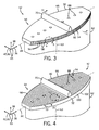
- FIG. 3 is a partial perspective view of another embodiment of the rotary blade 52 that forms part of the rotor 24 of a turbomachine.
- the rotary blade 52 includes the blade portion 62 and the tip portion 64 having the tip shroud 66. Further, the tip shroud 66 includes the seal tooth 70 for establishing a seal between the rotating rotary blade 52 and the non-rotating stator 60 of the turbomachine.
- the tip portion 64 includes an elongated shape along a longitudinal axis 84 of the tip portion 64, and this longitudinal axis 84 may be aligned with the axial direction 36.
- the blade portion 62 includes an elongated shape along the longitudinal axis 63 of the blade portion 62, and this longitudinal axis 63 may be aligned with the radial direction 38.
- the tip shroud 66 protrudes away from the blade portion 62 in a crosswise direction 86 (e.g., circumferential direction 40) relative to the longitudinal axes 63 and 84. Indeed, the tip shroud 66 protrudes from the blade portion 62 in opposite axial directions 36 and opposite crosswise directions 86 (e.g., opposite circumferential directions 40) relative to the longitudinal axis 63 of the rotary blade 52.
- this crosswise direction 86 may correspond to any direction that intersects the axial direction 36 and is generally angled (e.g., perpendicular) to the radial direction 38 (e.g., any direction in the plane 65 of the illustrated directions 36 and 86).
- the illustrated patterned structure 54 of the tip shroud 66 has the beams 56 (and cavities 58) oriented (e.g., elongated) in the crosswise direction 86. Since the beams 56 are configured to provide stiffness to the rotary blade 52, it may be desirable for the beams 56 to be oriented in a direction of stress and/or deflection of the rotary blade 52. This stress and/or deflection may be caused by the impact of combustion gases 22 on the blade portion 62, centrifugal force of the rotating rotary blade 52, and the like. A direction of maximum stress and/or deflection may be determined through empirical testing and/or simulations of the rotary blade 52 under expected loading conditions.
- the direction of stress and/or deflection may correspond to the crosswise direction 86 of the tip shroud 66. Therefore, the tip shroud 66 may protrude away from the blade portion 62 of the rotary blade 52 in opposite crosswise directions 86 relative to the longitudinal axis 84 of the blade portion 62, and the patterned structure 54 of beams 56 and cavities 58 may be oriented in the crosswise direction 86 to reduce the stress and/or deflection of the rotary blade 52 throughout operation. In other embodiments, the direction of stress and/or deflection may not correspond to the crosswise direction 86 in which the tip shroud 66 protrudes away from the longitudinal axes 63 and 84.
- the patterned structure 54 may be aligned with a direction of stress and/or deflection that is oriented approximately 0-90 ⁇ from the crosswise direction 86 (e.g., 45 ⁇ from both the longitudinal axis 84 and the crosswise direction 86).
- a direction of stress and/or deflection that is oriented approximately 0-90 ⁇ from the crosswise direction 86 (e.g., 45 ⁇ from both the longitudinal axis 84 and the crosswise direction 86).
- the patterned structure 54 of beams 56 and cavities 58 may be introduced to the rotary blade 52 of the turbomachine system 10 using one or more of several different manufacturing techniques.
- the desired technique for manufacturing the patterned structure 54 may be determined based on the desired structure of the tip shroud 66 of the rotary blade 52. For example, constructing the rotary blade 52 from multiple components that are secured together may allow a certain ease of manufacturing. However, any locations of bracing or connecting (e.g., welding) the different components of the rotary blade 52 may provide a location of internal stress concentration, where additional stiffness may be desired.
- the rotary blade 52 may include a one-piece structure having both the blade portion 62 and the tip portion 64, including the patterned structure 54, in order to reduce stress concentrations throughout the rotary blade 52.
- a one-piece structure may be constructed by casting the structure using a mold, coring the patterned structure 54 into the rotary blade 52, and/or machining the patterned structure 54 into the rotary blade 52 using plunge electrical discharge machining (EDM) techniques.
- EDM plunge electrical discharge machining
- Plunge EDM utilizes repetitive electrical discharges to remove small pieces of metal from a structure, and this technique may be applied to the rotary blade 52 to form the cavities 58 of the desired patterned structure 54.
- plunge EDM may allow a relatively small and precise pattern of beams 56 and cavities 58 to be formed in the rotary blade 52.
- the plunge EDM method may be limited, however, with regard to the depth to which the patterned structure 54 may be formed in the tip shroud 66 of the rotary blade 52.
- some plunge EDM machines may only be capable of penetrating a certain depth (e.g., approximately 2.5 cm) into a given material.
- the technique may still be used to increase a stiffness to weight ratio in the tip shroud 66, however, as plunge EDM may be used to form the patterned structure 54 in the crosswise direction 86 from circumferentially opposite edges 90 and 92 of the tip shroud 66 extending away from the longitudinal axis 84.
- the patterned structure 54 may reach from both edges 90 and 92 and connect in the middle, or there may be a solid layer of material remaining toward the center (e.g., along axis 84) of the tip shroud 66, between the two patterned structures 54. It may be possible to construct the patterned structure 54 such that certain of the cavities 58 are formed through the tip shroud 66 to different depths to achieve a desired distribution of stiffness throughout the tip shroud 66 based on the expected levels of stress concentration therein. Regardless of the manufacturing technique or the depth of the patterned structure 54, the increased stiffness to weight ratio provided by the beams 56 and cavities 58 may allow the use of a relatively larger tip shroud 66 to provide greater coverage to the tip portion 64 of the rotary blade 52.
- the tip shroud 66 also may include a number of cooling holes 88 formed therein for cooling the rotary blade 52. As illustrated in FIG. 1 , air may be permitted to flow into the hollow blade portion 62 of the rotary blade 52, thereby reducing a temperature of the rotary blade 52. In certain rotary blade arrangements, this air may exit the rotary blade 52 through the cooling holes 88 that are oriented in the radial direction 38. As illustrated, the cooling holes 88 are spaced apart in alignment with axis 84, but the cooling holes 88 could be in any other arrangement.
- the patterned structure 54 includes cavities 58 that are oriented in the crosswise direction 86, which may be perpendicular to the radial direction 38, the cavities 58 may intersect internal passages that direct air to the cooling holes 88. This may allow air to flow through the tip shroud 66 in the crosswise direction 86 as well, cooling a greater portion of the rotary blade 52. However, in some embodiments, the cooling holes 88 do not intersect the patterned structure 54, and thus no coolant (e.g., cooling air) can flow through the cavities 58 in the patterned structure 54.
- coolant e.g., cooling air
- FIG. 4 is a partial perspective view of an embodiment of the rotary blade 52 with the patterned structure 54 of beams 56 and cavities 58 extending along an exterior portion 98 (e.g., radially outward face) of the tip shroud 66.
- the rotary blade 52 has a similar shape and arrangement of certain components of the rotary blade 52 of FIG. 3 , but the patterned structure 54 has at least a portion of the beams 56 and cavities 58 extending along the upper exterior portion 98 of the tip shroud 66.
- the beams 56 and cavities 58 may be parallel protrusions and slots, respectively, which extend the full distance or less than the full distance between the opposite edges 90 and 92.
- This arrangement of the patterned structure 54 may be easier to manufacture than a more internal arrangement of the patterned structure 54 (e.g., FIG. 3 ), while providing a desired increase in the stiffness to weight ratio of the tip shroud 66.
- the beams 56 and cavities 58 may be oriented (e.g., elongated) in the crosswise direction 86 (e.g., circumferential direction 40) to increase stiffness of the tip shroud 66 in a direction of stress and/or deflection, as previously mentioned.
- the patterned structure 54 also may include multiple layers of the beams 56 and cavities 58 extending through the tip shroud 66 at positions away from (e.g., radially recessed into) the exterior portion 98, in addition to extending along the exterior portion 98.
- the patterned structure 54 may extend along other exterior portions (e.g., a lateral perimeter portion 100 and/or underside portion 102) of the tip shroud 66 instead of or in addition to the upper exterior portion 98 of the tip shroud 66.
- the lateral perimeter portion 100 may include the opposite edges 90 and 92.
- the beams 56 and cavities 58 extending along the exterior portion 98 may or may not intersect the cooling holes 88 of the rotary blade 52.
- FIGS. 5-7 are side views of different embodiments of the rotary blade 52 of FIG. 3 , taken within line 5-5, illustrating different patterned structures 54 of beams 56 and cavities 58 that may be utilized to improve the stiffness to weight ratio of the rotary blade 52.
- increasing this ratio may allow a rotary blade 52 with a larger tip shroud 66 to be used with the rotor 24, improving performance of the turbomachine system 10 (e.g., increasing turbine or compressor stage efficiency).
- this increase in the stiffness to weight ratio may be particularly effective when the beams 56 and cavities 58 are aligned in a direction of stress and/or deflection of the rotary blade 52.
- FIGS. 5-7 are side views of different embodiments of the rotary blade 52 of FIG. 3 , taken within line 5-5, illustrating different patterned structures 54 of beams 56 and cavities 58 that may be utilized to improve the stiffness to weight ratio of the rotary blade 52.
- increasing this ratio may allow a rotary blade 52 with a larger tip shroud 66
- the patterned structure 54 of beams 56 and cavities 58 may include multiple layers of beams 56 and cavities 58 within the tip shroud 66.
- the patterned structure 54 of the tip shroud 66 may include any number of layers of beams 56 and cavities 58 (e.g., 1 to 100 layers) stacked one over another in the radial direction 38, and such layered arrangements of the patterned structure 54 will be apparent in FIGS. 5-7
- FIG. 5 illustrates the patterned structure 54 having substantially rectangular beams 56 and cavities 58.
- the beams 56 may act as I-beams within the patterned structure 54, reducing a deflection of the tip shroud 66 in response to external and/or internal forces on the tip shroud 66 in the crosswise direction 86.
- the beams 56 and cavities 58 may be aligned with a direction of relatively high stress and/or deflection in order to offer greater stiffness where desired, while using less material.
- the patterned structure 54 includes multiple layers (e.g., stacked one over another) of beams 56 and cavities 58 arranged within the tip shroud 66.
- This patterned structure 54 includes beams 56 and cavities 58 that are approximately equal in size and equally spaced, arranged in multiple layers that are both vertically and horizontally aligned. However, other arrangements of the patterned structure 54 of beams 56 and cavities 58 may be employed, as described in detail below. As previously described, the patterned structure 54 may be formed into the rotary blade 52 using plunge EDM. This technique may allow the patterned structure 54 to be precisely constructed to a desired size of beams 56 and cavities 58. For example, a desired width of the beams 56 may fall within a range of about .010-.040, .016-.034, .020-.028, or approximately .025 cm. In addition, a desired width of the cavities may fall within a range of about .010-.040, .012-.030, .014-.020, or approximately .018 cm.
- FIG. 6 illustrates the patterned structure 54 having substantially circular cavities 58.
- This arrangement allows the cavities 58 to roughly define the beams 56 as the portions of the tip shroud 66 located between the cavities 58.
- the cavities 58 and the beams 56 are approximately equally spaced from one another but staggered vertically and horizontally.
- the illustrated embodiment shows the cavities 58 arranged diagonally within the plane.
- the beams 56 and cavities 58 extend into the tip shroud 66 in the same direction, maintaining a parallel alignment with one another no matter what repeated pattern is used.
- the patterned structure 54 may include any number of layers of the beams 56 and cavities 58.
- FIG. 7 illustrates the tip shroud 66 having the patterned structure 54 of beams 56 and cavities 58 disposed between two plate portions 110 and 112. That is, the tip shroud 66 includes a radially inner plate portion 110 and a radially outer plate portion 112 disposed about the patterned structure 54 (e.g., multiple layers of beams 56 and cavities 58), providing additional stiffness to the tip shroud 66.
- the illustrated patterned structure 54 includes three layers of the beams 56 alternating with four layers of the cavities 58, any numbers of layers of beams 56 and cavities 58 (e.g., 1 to 100 layers) may be possible.
- the radially inner plate portion 110 may be a plate located relatively toward the rotational axis 26 of the rotor 24, forming a lower surface of the tip shroud 66 in the inward radial direction 38.
- the radially outer plate portion 112 may be a plate located relatively away from the rotational axis 26 of the rotor 24, forming an upper surface of the tip shroud 66 in the outward radial direction 38.
- the radially inner plate portion 110, patterned structure 54 of beams 56 and cavities 58, and radially outer plate portion 112 may make up a one-piece structure.
- the rotary blade 52 may be an entirely one-piece structure having the tip shroud 66 with the patterned structure 54 disposed between the plate portions 110 and 112.
- EDM plunging techniques may be used to create the cavities 58 in an otherwise solid piece of the tip shroud 66 or rotary blade 52 in such a way that plate portions 110 and 112 are integral with the patterned structure 54 of beams 56 and cavities 58.
- the patterned structure 54 may be separate from, and secured between, the plate portions 110 and 112. This may provide greater ease of manufacturing than constructing the patterned structure 54 and plate portions 110 and 112 from a single piece of material.
- a one-piece structure may further improve stiffness to resist stresses and/or deflections of the tip shroud 66, since there are no connections between separate components that may contribute additional stress concentrations.
- the radially inner plate portion 110 and radially outer plate portion 112 may be thicker or thinner than the beams 56 of the patterned structure 54 between the plate portions 110 and 112.
- the patterned structure 54 between the plate portions 110 and 112 may include any pattern of beams 56 and cavities 58, e.g., the previously described rectangular beams 56 and cavities 58 of FIG. 5 , the diagonal arrangement of circular cavities 58 of FIG. 6 , and other variations and/or combinations of these patterned structures 54.
- the plate portions 110 and 112 may be constructed from different materials and/or from a different material than the patterned structure 54.
- the tip shroud 66 may include a greater number (e.g., 3, 4, 5, 6, 7, 8, 9, or 10) of radially arranged plate portions disposed about multiple sections of patterned structures 54 of beams 56 and cavities 58.
- the tip shroud 66 may include a radially intermediate plate portion located between the radially inner plate portion 110 and radially outer plate portion 112, secured between two layers of the patterned structure 54 or included as one piece with the patterned structure 54. Additional variations and/or combinations of the arrangements of patterned structures 54 shown in FIGS. 5-7 may be possible as well.
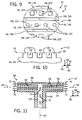
- FIGS. 8 and 9 are top views of embodiments of the rotary blade 52 of FIG. 4 , taken within line 8-8, illustrating the patterned structure 54 extending along the exterior portion 98 of the rotary blade 52.
- the stiffness of the rotary blade 52 may be maintained in a desired direction (i.e., the direction along which the beams 56 and cavities 58 are oriented) while the weight of the rotary blade 52 is slightly reduced.
- FIG. 8 illustrates the beams 56 and cavities 58 arranged in substantially rectangular rows, where the beams 56 extend farther from the exterior portion 98 (in the radial direction 38) than the cavities 58.
- the beams 56 and cavities 58 are approximately the same width, but other variations of beam thickness may be possible.
- FIG. 9 illustrates the patterned structure 54 having a plurality of alternating sets of the beams 56 and cavities 58. That is, the patterned structure 54 includes at least a first set of beams 56, 116 and cavities 58, 118, and a second set of beams 56, 120 and cavities 58, 122.
- the first set of beams 56, 116 and cavities 58, 118 extends along the exterior portion 98 of the rotary blade 52, oriented in the crosswise direction 86
- the second set of beams 56, 120 and cavities 58, 122 is oriented in the radial direction 38.
- some of the cavities 58, 122 are substantially rectangular and some of the cavities 58, 122 are substantially circular.
- multiple sets which may include different arrangements and/or different orientations of beams 56 and cavities 58, may be combined to achieve a desired stiffness to weight ratio of one or more portions of the rotary blade 52.
- the multiple sets if oriented differently as illustrated, may use the beams 56 to increase stiffness of the rotary blade 52 in more than one direction (e.g., axial 36, radial 38, and/or circumferential 40) that may experience stress and/or deflection throughout operations of the turbomachine system 10.
- FIG. 10 is a side view of an embodiment of the rotary blade 52 of FIG. 4 , taken within line 10-10, illustrating the patterned structure 54 of beams 56 and cavities 58 extending from the exterior portion 98 of the rotary blade 52.
- the side view of the illustrated patterned structure 54 is a view in the crosswise direction 86 in which the patterned structure 54 extends.
- This particular patterned structure 54 may correspond with the patterned structure 54 of FIG. 8 , where the beams 56 and the cavities 58 are approximately the same width.
- the illustrated embodiment shows the beams 56 of the patterned structure 54 extending along the exterior portion 98 of the rotary blade 52 and the cavities 58 formed beneath the exterior portion 98. Therefore, the cavities 58 reduce a weight of the rotary blade 52, while the beams 56 maintain a desired support and stiffness of the rotary blade 52 in the crosswise direction 86 in which the beams 56 extend.
- FIG. 11 is a partial front cross-sectional view of an embodiment of the rotary blade 52 of FIG. 3 , taken within line 11-11, illustrating airflow through the patterned structure 54 of beams 56 and cavities 58 in the rotary blade 52.
- Air may enter the hollow blade portion 62 of the rotary blade 52 near the rotational axis 26 and travel outward in the radial direction 38 through the blade portion 62 (arrows 74). This air movement may provide convective cooling to the blade portion 62 of the rotary blade 52, which may be designed to endure relatively high temperatures (e.g., approximately 540 ⁇ C).
- the patterned structure 54 of beams 56 and cavities 58 extends in the crosswise direction 86 entirely through the tip shroud 66, intersecting the hollowed section 130 of the tip portion 64 through which the air flows toward the cooling holes 88.
- the illustrated cross section does not include cooling holes 88, but other cross sections of the rotary blade 52 may include one or more cooling holes 88 that allow the air to escape through the upper exterior portion 98 of the tip shroud 66.
- the air also flows through the cavities 58 of the patterned structure 54, providing convective cooling to a greater inner surface area of the tip shroud 66.
- the air is then expelled from the cavities 58 of the patterned structure 54 in the tip shroud 66, as shown by arrows 76.
- This arrangement of the patterned structure 54 may provide more cooling than is generally available in tip shrouds 66 having airflow through only the cooling holes 88 in the upper exterior portion 98 of the rotary blade 52. Again, other embodiments of the patterned structure 54 do not intersect the hollowed section 130, and thus do not pass any coolant flow.
- inventions include, among other things, increasing a stiffness to weight ratio of a rotary blade in a turbomachine system through a patterned structure of beams and cavities formed in a tip shroud of the rotary blade.
- the beams of the patterned structure e.g., honeycomb, grid of cavities, grill of beams, etc.
- the cavities of the patterned structure reduce the weight of the tip shroud, such that a relatively larger tip shroud may be used to provide the same amount of stiffness and rotary blade weight to the turbomachine system.
- a larger tip shroud on the rotary blade may improve the performance of a turbine system in which the rotary blade rotates. That is, the larger tip shroud may provide increased coverage of the rotary blade tip and an improved seal to direct a greater amount of combustion gases through the turbine blades in an axial direction, thereby increasing an efficiency of the turbomachine.
- the patterned structure of beams and cavities may provide additional cooling passages through the rotary blade. Air may enter the blade portion and exit through the cavities of the patterned structure formed in the tip shroud, providing more extensive cooling to the tip shroud as the rotary blade rotates.
Landscapes
- Engineering & Computer Science (AREA)
- Mechanical Engineering (AREA)
- General Engineering & Computer Science (AREA)
- Architecture (AREA)
- Turbine Rotor Nozzle Sealing (AREA)
- Structures Of Non-Positive Displacement Pumps (AREA)
Abstract
Description
- The subject matter disclosed herein relates to turbomachines and, more particularly, to a turbomachine blade with an improved stiffness to weight ratio.
- Turbomachine systems include gas turbines, steam turbines, hydro turbines, compressors, and other rotating machinery. In general, such turbomachines are configured to use rotary blades to extract energy from a fluid flow, such as gas, steam, or water. For instance, the rotary blades may extend radially outwards from a supporting rotor, and the rotary blades may force rotation of the rotor as the fluid flow passes across the rotary blades. Certain turbomachines include rotary blades having a tip shroud located at a tip portion of each rotary blade extending from the rotor for added stiffness and stability. Unfortunately, existing designs of tip shrouds on such rotary blades may limit performance of the turbomachine system. For example, the size of the tip shroud (i.e., rotary blade tip coverage) may be restricted for tip shrouds based on tip shroud weight. Consequently, a stiffness to weight ratio of a tip shroud designed to provide a desired stiffness may limit the available rotary blade tip coverage, thereby limiting the efficiency of the turbomachine.
- Certain embodiments commensurate in scope with the originally claimed invention are summarized below. These embodiments are not intended to limit the scope of the claimed invention, but rather these embodiments are intended only to provide a brief summary of possible forms of the invention. Indeed, the invention may encompass a variety of forms that may be similar to or different from the embodiments set forth below.
- In a first aspect, the invention resides in a system including at least one rotary blade having a blade portion and a tip portion. The tip portion includes a patterned structure of beams and cavities.
- In a second aspect, the invention resides in a system including a turbomachine including a stator and a rotor configured to rotate about a rotational axis relative to the stator. The rotor includes at least one rotary blade having a patterned structure of beams and cavities.
- In a third aspect, the invention resides in a system including a tip portion of a rotary blade including a tip shroud having a patterned structure of beams and cavities. The tip shroud is configured to protrude away from a blade portion of the rotary blade in a crosswise direction relative to a longitudinal axis of the blade portion. The patterned structure has the beams oriented in the crosswise direction to reduce stress and/or deflection. The patterned structure has the cavities to reduce weight of the tip portion.
- These and other features, aspects, and advantages of the present invention will become better understood when the following detailed description is read with reference to the accompanying drawings in which like characters represent like parts throughout the drawings, wherein:
-
FIG. 1 is a schematic of an embodiment of a turbomachine system including a turbine having a turbine blade with a patterned structure of beams and cavities; -
FIG. 2 is a side cross-sectional view of an embodiment of the turbomachine system ofFIG. 1 , taken within line 2-2, illustrating a rotary blade having a patterned structure of beams and cavities; -
FIG. 3 is a partial perspective view of an embodiment of a rotary blade with a patterned structure of beams and cavities oriented in a crosswise direction; -
FIG. 4 is a partial perspective view of an embodiment of a rotary blade with a patterned structure of beams and cavities extending along an exterior portion of a tip shroud; -
FIG. 5 is a side view of an embodiment of the rotary blade ofFIG. 3 , taken within line 5-5, illustrating a patterned structure of substantially rectangular beams and cavities; -
FIG. 6 is a side view of an embodiment of the rotary blade ofFIG. 3 , taken within line 5-5, illustrating a patterned structure of beams and substantially circular cavities; -
FIG. 7 is a side view of an embodiment of the rotary blade ofFIG. 3 , taken within line 5-5, illustrating a patterned structure of substantially rectangular beams and circular cavities disposed between a radially inner plate portion and a radially outer plate portion; -
FIG. 8 is a top view of an embodiment of the rotary blade ofFIG. 4 , taken within line 8-8, illustrating a patterned structure of substantially rectangular beams and cavities; -
FIG. 9 is a top view of an embodiment of the rotary blade ofFIG. 4 , taken within line 8-8, illustrating a patterned structure having alternating sets of beams and cavities; -
FIG. 10 is a side view of an embodiment of the rotary blade ofFIG. 4 , taken within line 10-10, illustrating a patterned structure of beams and cavities disposed in a laterally protruding exterior portion of the blade; and -
FIG. 11 is a front cross-sectional view of an embodiment of the rotary blade ofFIG. 3 , taken within line 11-11, illustrating airflow through a patterned structure of beams and cavities in the rotary blade. - One or more specific embodiments of the present invention will be described below. In an effort to provide a concise description of these embodiments, all features of an actual implementation may not be described in the specification. It should be appreciated that in the development of any such actual implementation, as in any engineering or design project, numerous implementation-specific decisions must be made to achieve the developers' specific goals, such as compliance with system-related and business-related constraints, which may vary from one implementation to another. Moreover, it should be appreciated that such a development effort might be complex and time consuming, but would nevertheless be a routine undertaking of design, fabrication, and manufacture for those of ordinary skill having the benefit of this disclosure.
- When introducing elements of various embodiments of the present invention, the articles "a," "an," "the," and "said" are intended to mean that there are one or more of the elements. The terms "comprising," "including," and "having" are intended to be inclusive and mean that there may be additional elements other than the listed elements.
- The present disclosure is directed to systems for improving a stiffness to weight ratio of rotating turbomachinery components (e.g., a rotary blade of a turbomachine system). The rotary blade (e.g., turbine blade or compressor blade) includes a patterned structure of beams and cavities for increasing the stiffness to weight ratio of a tip shroud of the rotary blade. The patterned structure may be formed through the tip shroud, extended along an exterior portion of the tip shroud, or a combination thereof. The beams and cavities of the patterned structure may be aligned in a crosswise direction relative to a longitudinal axis of the rotary blade. In some embodiments, the beams and cavities may be oriented such that they align with a direction of stress and/or deflection of the rotary blade. Indeed, the beams may increase a stiffness of the rotary blade in the direction of orientation of the patterned structure, while the cavities reduce the overall weight of the patterned structure. By increasing the stiffness to weight ratio of the rotary blade, the patterned structure of beams and cavities may be applied to a relatively larger tip shroud than would be possible on a rotary blade without the patterned structure.
- Turning now to the drawings,
FIG. 1 illustrates a block diagram of an embodiment of a turbomachine system 10 (e.g., gas turbine system) havingturbine blades 12 and/orcompressor blades 30 that include patterned structures of beams and cavities. The patterned structure of beams and cavities, described in detail below, may be a honeycomb pattern, grid of crosswise beams, grill of parallel beams, or a combination thereof. Thesystem 10 includes acompressor 14,combustors 16 havingfuel nozzles 18, and aturbine 20. The fuel nozzles 18 route a liquid fuel and/or gas fuel, such as natural gas or syngas, into thecombustors 16. Thecombustors 16 ignite and combust a fuel-air mixture, and then pass hot pressurized combustion gases 22 (e.g., exhaust) into theturbine 20.Turbine blades 12 are coupled to arotor 24, which is also coupled to several other components throughout theturbomachine system 10, as illustrated. As thecombustion gases 22 pass through theturbine blades 12 in theturbine 20, theturbine 20 is driven into rotation, which causes therotor 24 to rotate about arotational axis 26. Eventually, thecombustion gases 22 exit theturbine 20 via anexhaust outlet 28. - In the illustrated embodiment, the
compressor 14 includescompressor blades 30. Thecompressor blades 30 within thecompressor 14 are coupled to therotor 24, and rotate as therotor 24 is driven into rotation by theturbine 20, as discussed above. As thecompressor blades 30 rotate within thecompressor 14, theblades 30 compress air from an air intake into pressurizedair 32, which may be routed to thecombustors 16, thefuel nozzles 18, and other portions of thegas turbomachine system 10. Thefuel nozzles 18 may then mix the pressurized air and fuel to produce a suitable fuel-air mixture, which combusts in thecombustors 16 to generate thecombustion gases 22 to drive theturbine 20. Further, therotor 24 may be coupled to aload 34, which may be powered via rotation of therotor 24. By way of example, theload 34 may be any suitable device that may generate power via the rotational output of theturbomachine system 10, such as a power generation plant or an external mechanical load. For instance, theload 34 may include an electrical generator, a propeller of an airplane, and so forth. In the following discussion, reference may be made to various directions, such as an axial direction oraxis 36, a radial direction oraxis 38, and a circumferential direction oraxis 40 of theturbomachine system 10. -
FIG. 2 is a partial side cross-sectional view of an embodiment of theturbomachine system 10 ofFIG. 1 , taken within line 2-2, illustrating a rotary blade 52 (e.g.,turbine blade 12 or compressor blade 30) having a patternedstructure 54 ofbeams 56 andcavities 58. Although the illustrated embodiment shows therotary blade 52 in the context of theturbine 20, thepatterned structure 54 may be applied to a rotating component of any turbomachine (e.g.,compressor 14,turbine 20, or a combination thereof). Theturbine 20 ofFIG. 2 includes therotor 24 and a stator 60 (i.e., stationary component of the turbine 20), and therotor 24 is configured to rotate in thecircumferential direction 40 about therotational axis stator 60. Therotor 24 may include one or more of the rotary blades 52 (e.g.,turbine blades 12,compressor blades 30, or rotating buckets), since theserotary blades 52 extend radially 38 outward from therotor 24. For example, therotor 24 may include 10 to 1000blades 52 circumferentially 40 spaced about theaxis rotor 24 in one or more stages of thecompressor 14 and/or theturbine 20. As previously mentioned, combustion of a fuel-air mixture in thecombustors 16 releases pressurizedcombustion gases 22 to theturbine 20, and thesegases 22 travel through theturbine 20 in theaxial direction 36, passing against and around therotary blade 52 to drive the rotation of therotor 24. - The
rotary blade 52 includes ablade portion 62 and atip portion 64, theblade portion 62 extending radially outward (as defined by the radial axis 38) and thetip portion 64 being located at a distal end of theblade portion 62 relative to therotor 24. The blade portion 62 (e.g., airfoil) may be the portion of therotary blade 52 that is forced by thecombustion gases 22 to rotate about therotational axis 26, driving the rotation of therotor 24 relative to thestator 60. Theblade portion 62 may be specifically contoured or shaped to maximize the rotation of therotor 24 caused by thesecombustion gases 22. Thetip portion 64 of therotary blade 52 may include atip shroud 66 that protrudes laterally away from therotary blade 52 in order to inhibit escape of thecombustion gases 22 radially beyond thetip portion 64, thereby maintaining a flow of thecombustion gases 22 in theaxial direction 36. For example, thetip shroud 66 may extend in a crosswise direction (e.g., perpendicular) relative to alongitudinal axis 63 of therotary blade 52. By further example, thetip shroud 66 may extend along aplane 65 that is substantially perpendicular to theaxis 63. Furthermore, thetip shroud 66 may protrude laterally (e.g., in plane 65) away from theblade portion 62 in oppositeaxial direction 36 and oppositecircumferential direction 40. By reducing the escape ofcombustion gases 22 away from theblade portion 62 of therotary blade 52, thetip shroud 66 may increase an efficiency of theturbine 20. The illustratedtip shroud 66 includes astiffener rail 68 and aseal tooth 70 extending radially 38 from thetip shroud 66 toward thestator 60 of theturbine 20. Thestiffener rail 68 may increase the stiffness of thetip shroud 60 in a desired direction, reducing the effect of certain stresses and/or deflections on thetip portion 64 as therotary blade 52 rotates. Theseal tooth 70 of thetip shroud 66 extends relatively closer to thestator 60, creating a seal between therotating rotor 24, which includes therotary blade 52, and thenon-rotating stator 60 of theturbomachine system 10. This may further direct thecombustion gases 22 to travel axially (e.g., in the axial direction 36) through theturbine 20, instead of between therotary blades 52 and thestator 60. - In the illustrated embodiment, the
tip shroud 66 includes the patternedstructure 54 ofbeams 56 andcavities 58, which is discussed in detail below. As mentioned above, the patternedstructure 54 may be a honeycomb structure, a grid ofcrosswise cavities 58, a grill ofparallel beams 56, or other similarly repeating patterns. The patterned structure 54 (e.g., honeycomb, grid of cavities, grill of beams, etc.) may be applied in a variety of arrangements, patterns, orientations, and locations of therotary blade 52. For example, the patternedstructure 54 may be applied to the tip portion 64 (e.g., outermost 1 to 50 % of the radial length) of arotary blade 52 that does not include atip shroud 66. In addition, the patternedstructure 54 may include any number of layers ofbeams 56 and cavities 58 (e.g., 1 to 100 layers) stacked one over another in theradial direction 38. Thebeams 56 of the patternedstructure 54 may be oriented to increase stiffness of thetip portion 64 of therotary blade 52 in a desired direction, thereby improving a resistance of therotary blade 52 to stresses and/or deflections, which may be caused by the force of thepressurized combustion gas 22, centrifugal force of the rotating machinery, etc. The patternedstructure 54 features thecavities 58 to reduce the weight of thetip shroud 66 ortip portion 64 of therotary blade 52. Thus, thepatterned structures 54 may increase a stiffness to weight ratio of thetip shroud 66 ortip portion 64 of therotary blade 52 in a desired direction. Increasing this ratio may allow a relativelylarger tip shroud 66 to be used because of the reduction in weight of thetip shroud 66 for achieving a desired stiffness. Furthermore, thelarger tip shroud 66 may provide better coverage of thetip portion 64 of therotary blade 52, further reducing the amount of thecombustion gas 22 that escapes therotary blades 52. In this way, the turbine stage efficiency of theturbomachine system 10 may be improved. In addition, increasing the ratio of stiffness to weight within thetip shroud 66 may allow alighter tip portion 64 to be used for therotary blade 52. Such alighter rotary blade 52 may be easier to accelerate and helpful for balancing therotary blade 52. A relatively larger amount of weight of therotary blade 52 may be concentrated toward therotor 24 and less weight may be concentrated at thetip portion 64. As a result, the centrifugal force due to rotation of therotary blade 52 may be lessened, and this may decrease the amount of deflection of therotary blade 52. - In certain embodiments, the patterned
structure 54 may be completely independent from or unrelated to any coolant flows (e.g., airflow through the rotary blade 52). In other embodiments, the patternedstructure 54 may be used in conjunction with coolant flows. For example, thecavities 58 of the patternedstructure 54 formed in thetip shroud 66 also may provide additional channels for cooling therotary blade 52. Heat from the pressurizedcombustion gas 22 combined with the rotational motion of therotor 24 may increase the temperature of therotary blade 52 significantly, and additional cooling of theblade 52 may be desired. Indeed, theblade portion 62 of therotary blade 52 may be hollow, as illustrated inFIG. 2 , allowing coolant (e.g., air) to flow into therotary blade 52 from therotor 24, as shown byarrows 72. The air may travel through therotary blade 52, as shown byarrows 74, to cool the blade from theblade portion 62 to thetip portion 64 through forced air convection. The cooling air may then exit therotary blade 52 through thecavities 58 of the patternedstructure 54 in thetip shroud 66, as shown byarrows 76. Thus, optional cooling may be provided to thetip shroud 66 as well as to theblade portion 62 of therotary blade 52. -
FIG. 3 is a partial perspective view of another embodiment of therotary blade 52 that forms part of therotor 24 of a turbomachine. Therotary blade 52 includes theblade portion 62 and thetip portion 64 having thetip shroud 66. Further, thetip shroud 66 includes theseal tooth 70 for establishing a seal between therotating rotary blade 52 and thenon-rotating stator 60 of the turbomachine. Thetip portion 64 includes an elongated shape along alongitudinal axis 84 of thetip portion 64, and thislongitudinal axis 84 may be aligned with theaxial direction 36. Also, theblade portion 62 includes an elongated shape along thelongitudinal axis 63 of theblade portion 62, and thislongitudinal axis 63 may be aligned with theradial direction 38. Thetip shroud 66 protrudes away from theblade portion 62 in a crosswise direction 86 (e.g., circumferential direction 40) relative to thelongitudinal axes tip shroud 66 protrudes from theblade portion 62 in oppositeaxial directions 36 and opposite crosswise directions 86 (e.g., opposite circumferential directions 40) relative to thelongitudinal axis 63 of therotary blade 52. Although illustrated as being perpendicular to both theaxial direction 36 andradial direction 38, thiscrosswise direction 86 may correspond to any direction that intersects theaxial direction 36 and is generally angled (e.g., perpendicular) to the radial direction 38 (e.g., any direction in theplane 65 of the illustrateddirections 36 and 86). - The illustrated patterned
structure 54 of thetip shroud 66 has the beams 56 (and cavities 58) oriented (e.g., elongated) in thecrosswise direction 86. Since thebeams 56 are configured to provide stiffness to therotary blade 52, it may be desirable for thebeams 56 to be oriented in a direction of stress and/or deflection of therotary blade 52. This stress and/or deflection may be caused by the impact ofcombustion gases 22 on theblade portion 62, centrifugal force of therotating rotary blade 52, and the like. A direction of maximum stress and/or deflection may be determined through empirical testing and/or simulations of therotary blade 52 under expected loading conditions. Indeed, the direction of stress and/or deflection may correspond to thecrosswise direction 86 of thetip shroud 66. Therefore, thetip shroud 66 may protrude away from theblade portion 62 of therotary blade 52 in opposite crosswisedirections 86 relative to thelongitudinal axis 84 of theblade portion 62, and the patternedstructure 54 ofbeams 56 andcavities 58 may be oriented in thecrosswise direction 86 to reduce the stress and/or deflection of therotary blade 52 throughout operation. In other embodiments, the direction of stress and/or deflection may not correspond to thecrosswise direction 86 in which thetip shroud 66 protrudes away from thelongitudinal axes structure 54 may be aligned with a direction of stress and/or deflection that is oriented approximately 0-90□ from the crosswise direction 86 (e.g., 45□ from both thelongitudinal axis 84 and the crosswise direction 86). By orienting the patternedstructure 54 in the direction of highest expected stress and/or deflection, a higher stiffness to weight ratio of therotary blade 52 may be achieved, as thebeams 56 provide stiffness in the desired direction and thecavities 58 reduce the weight. - The patterned
structure 54 ofbeams 56 andcavities 58 may be introduced to therotary blade 52 of theturbomachine system 10 using one or more of several different manufacturing techniques. Moreover, the desired technique for manufacturing the patternedstructure 54 may be determined based on the desired structure of thetip shroud 66 of therotary blade 52. For example, constructing therotary blade 52 from multiple components that are secured together may allow a certain ease of manufacturing. However, any locations of bracing or connecting (e.g., welding) the different components of therotary blade 52 may provide a location of internal stress concentration, where additional stiffness may be desired. Therefore, it may be desirable for therotary blade 52 to include a one-piece structure having both theblade portion 62 and thetip portion 64, including the patternedstructure 54, in order to reduce stress concentrations throughout therotary blade 52. Such a one-piece structure may be constructed by casting the structure using a mold, coring the patternedstructure 54 into therotary blade 52, and/or machining the patternedstructure 54 into therotary blade 52 using plunge electrical discharge machining (EDM) techniques. Plunge EDM utilizes repetitive electrical discharges to remove small pieces of metal from a structure, and this technique may be applied to therotary blade 52 to form thecavities 58 of the desired patternedstructure 54. Indeed, plunge EDM may allow a relatively small and precise pattern ofbeams 56 andcavities 58 to be formed in therotary blade 52. The plunge EDM method may be limited, however, with regard to the depth to which the patternedstructure 54 may be formed in thetip shroud 66 of therotary blade 52. For example, some plunge EDM machines may only be capable of penetrating a certain depth (e.g., approximately 2.5 cm) into a given material. The technique may still be used to increase a stiffness to weight ratio in thetip shroud 66, however, as plunge EDM may be used to form the patternedstructure 54 in thecrosswise direction 86 from circumferentially opposite edges 90 and 92 of thetip shroud 66 extending away from thelongitudinal axis 84. The patternedstructure 54 may reach from bothedges tip shroud 66, between the twopatterned structures 54. It may be possible to construct the patternedstructure 54 such that certain of thecavities 58 are formed through thetip shroud 66 to different depths to achieve a desired distribution of stiffness throughout thetip shroud 66 based on the expected levels of stress concentration therein. Regardless of the manufacturing technique or the depth of the patternedstructure 54, the increased stiffness to weight ratio provided by thebeams 56 andcavities 58 may allow the use of a relativelylarger tip shroud 66 to provide greater coverage to thetip portion 64 of therotary blade 52. - The
tip shroud 66 also may include a number of cooling holes 88 formed therein for cooling therotary blade 52. As illustrated inFIG. 1 , air may be permitted to flow into thehollow blade portion 62 of therotary blade 52, thereby reducing a temperature of therotary blade 52. In certain rotary blade arrangements, this air may exit therotary blade 52 through the cooling holes 88 that are oriented in theradial direction 38. As illustrated, the cooling holes 88 are spaced apart in alignment withaxis 84, but the cooling holes 88 could be in any other arrangement. Since the patternedstructure 54 includescavities 58 that are oriented in thecrosswise direction 86, which may be perpendicular to theradial direction 38, thecavities 58 may intersect internal passages that direct air to the cooling holes 88. This may allow air to flow through thetip shroud 66 in thecrosswise direction 86 as well, cooling a greater portion of therotary blade 52. However, in some embodiments, the cooling holes 88 do not intersect the patternedstructure 54, and thus no coolant (e.g., cooling air) can flow through thecavities 58 in the patternedstructure 54. -
FIG. 4 is a partial perspective view of an embodiment of therotary blade 52 with the patternedstructure 54 ofbeams 56 andcavities 58 extending along an exterior portion 98 (e.g., radially outward face) of thetip shroud 66. Therotary blade 52 has a similar shape and arrangement of certain components of therotary blade 52 ofFIG. 3 , but the patternedstructure 54 has at least a portion of thebeams 56 andcavities 58 extending along theupper exterior portion 98 of thetip shroud 66. Thebeams 56 andcavities 58 may be parallel protrusions and slots, respectively, which extend the full distance or less than the full distance between theopposite edges structure 54 may be easier to manufacture than a more internal arrangement of the patterned structure 54 (e.g.,FIG. 3 ), while providing a desired increase in the stiffness to weight ratio of thetip shroud 66. Indeed, thebeams 56 andcavities 58 may be oriented (e.g., elongated) in the crosswise direction 86 (e.g., circumferential direction 40) to increase stiffness of thetip shroud 66 in a direction of stress and/or deflection, as previously mentioned. The patternedstructure 54 also may include multiple layers of thebeams 56 andcavities 58 extending through thetip shroud 66 at positions away from (e.g., radially recessed into) theexterior portion 98, in addition to extending along theexterior portion 98. In other embodiments, the patternedstructure 54 may extend along other exterior portions (e.g., alateral perimeter portion 100 and/or underside portion 102) of thetip shroud 66 instead of or in addition to theupper exterior portion 98 of thetip shroud 66. Thelateral perimeter portion 100 may include theopposite edges beams 56 andcavities 58 extending along theexterior portion 98 may or may not intersect the cooling holes 88 of therotary blade 52. -
FIGS. 5-7 are side views of different embodiments of therotary blade 52 ofFIG. 3 , taken within line 5-5, illustrating differentpatterned structures 54 ofbeams 56 andcavities 58 that may be utilized to improve the stiffness to weight ratio of therotary blade 52. As mentioned before, increasing this ratio may allow arotary blade 52 with alarger tip shroud 66 to be used with therotor 24, improving performance of the turbomachine system 10 (e.g., increasing turbine or compressor stage efficiency). Furthermore, this increase in the stiffness to weight ratio may be particularly effective when thebeams 56 andcavities 58 are aligned in a direction of stress and/or deflection of therotary blade 52.FIGS. 5-7 illustrate differentpatterned structures 54 viewed from thecrosswise direction 86 in which thebeams 56 andcavities 58 are aligned. Thus, thesepatterned structures 54 are effectively shown from a side view and/or a cross-sectional view. As shown inFIGS. 5-7 , the patternedstructure 54 ofbeams 56 andcavities 58 may include multiple layers ofbeams 56 andcavities 58 within thetip shroud 66. As previously mentioned, the patternedstructure 54 of thetip shroud 66 may include any number of layers ofbeams 56 and cavities 58 (e.g., 1 to 100 layers) stacked one over another in theradial direction 38, and such layered arrangements of the patternedstructure 54 will be apparent inFIGS. 5-7 -
FIG. 5 illustrates the patternedstructure 54 having substantiallyrectangular beams 56 andcavities 58. Thebeams 56 may act as I-beams within the patternedstructure 54, reducing a deflection of thetip shroud 66 in response to external and/or internal forces on thetip shroud 66 in thecrosswise direction 86. Thebeams 56 andcavities 58 may be aligned with a direction of relatively high stress and/or deflection in order to offer greater stiffness where desired, while using less material. In the illustrated embodiment, the patternedstructure 54 includes multiple layers (e.g., stacked one over another) ofbeams 56 andcavities 58 arranged within thetip shroud 66. Thispatterned structure 54 includesbeams 56 andcavities 58 that are approximately equal in size and equally spaced, arranged in multiple layers that are both vertically and horizontally aligned. However, other arrangements of the patternedstructure 54 ofbeams 56 andcavities 58 may be employed, as described in detail below. As previously described, the patternedstructure 54 may be formed into therotary blade 52 using plunge EDM. This technique may allow the patternedstructure 54 to be precisely constructed to a desired size ofbeams 56 andcavities 58. For example, a desired width of thebeams 56 may fall within a range of about .010-.040, .016-.034, .020-.028, or approximately .025 cm. In addition, a desired width of the cavities may fall within a range of about .010-.040, .012-.030, .014-.020, or approximately .018 cm. -
FIG. 6 illustrates the patternedstructure 54 having substantiallycircular cavities 58. This arrangement allows thecavities 58 to roughly define thebeams 56 as the portions of thetip shroud 66 located between thecavities 58. Thecavities 58 and thebeams 56 are approximately equally spaced from one another but staggered vertically and horizontally. The illustrated embodiment shows thecavities 58 arranged diagonally within the plane. However, thebeams 56 andcavities 58 extend into thetip shroud 66 in the same direction, maintaining a parallel alignment with one another no matter what repeated pattern is used. As previously mentioned, the patternedstructure 54 may include any number of layers of thebeams 56 andcavities 58. -
FIG. 7 illustrates thetip shroud 66 having the patternedstructure 54 ofbeams 56 andcavities 58 disposed between twoplate portions tip shroud 66 includes a radiallyinner plate portion 110 and a radiallyouter plate portion 112 disposed about the patterned structure 54 (e.g., multiple layers ofbeams 56 and cavities 58), providing additional stiffness to thetip shroud 66. Although the illustrated patternedstructure 54 includes three layers of thebeams 56 alternating with four layers of thecavities 58, any numbers of layers ofbeams 56 and cavities 58 (e.g., 1 to 100 layers) may be possible. The radiallyinner plate portion 110 may be a plate located relatively toward therotational axis 26 of therotor 24, forming a lower surface of thetip shroud 66 in the inwardradial direction 38. Likewise, the radiallyouter plate portion 112 may be a plate located relatively away from therotational axis 26 of therotor 24, forming an upper surface of thetip shroud 66 in the outwardradial direction 38. The radiallyinner plate portion 110, patternedstructure 54 ofbeams 56 andcavities 58, and radiallyouter plate portion 112 may make up a one-piece structure. Likewise, therotary blade 52 may be an entirely one-piece structure having thetip shroud 66 with the patternedstructure 54 disposed between theplate portions cavities 58 in an otherwise solid piece of thetip shroud 66 orrotary blade 52 in such a way thatplate portions structure 54 ofbeams 56 andcavities 58. In other embodiments, the patternedstructure 54 may be separate from, and secured between, theplate portions structure 54 andplate portions tip shroud 66, since there are no connections between separate components that may contribute additional stress concentrations. - It should be noted that the radially
inner plate portion 110 and radiallyouter plate portion 112 may be thicker or thinner than thebeams 56 of the patternedstructure 54 between theplate portions structure 54 between theplate portions beams 56 andcavities 58, e.g., the previously describedrectangular beams 56 andcavities 58 ofFIG. 5 , the diagonal arrangement ofcircular cavities 58 ofFIG. 6 , and other variations and/or combinations of these patternedstructures 54. In embodiments where the patternedstructure 54 is separate from and secured between theplate portions plate portions structure 54. Furthermore, thetip shroud 66 may include a greater number (e.g., 3, 4, 5, 6, 7, 8, 9, or 10) of radially arranged plate portions disposed about multiple sections of patternedstructures 54 ofbeams 56 andcavities 58. For example, thetip shroud 66 may include a radially intermediate plate portion located between the radiallyinner plate portion 110 and radiallyouter plate portion 112, secured between two layers of the patternedstructure 54 or included as one piece with the patternedstructure 54. Additional variations and/or combinations of the arrangements of patternedstructures 54 shown inFIGS. 5-7 may be possible as well. -
FIGS. 8 and9 are top views of embodiments of therotary blade 52 ofFIG. 4 , taken within line 8-8, illustrating the patternedstructure 54 extending along theexterior portion 98 of therotary blade 52. By including the patternedstructure 54 ofbeams 56 andcavities 58 along theexterior portion 98 of therotary blade 52, the stiffness of therotary blade 52 may be maintained in a desired direction (i.e., the direction along which thebeams 56 andcavities 58 are oriented) while the weight of therotary blade 52 is slightly reduced.FIG. 8 illustrates thebeams 56 andcavities 58 arranged in substantially rectangular rows, where thebeams 56 extend farther from the exterior portion 98 (in the radial direction 38) than thecavities 58. In the illustrated embodiment, thebeams 56 andcavities 58 are approximately the same width, but other variations of beam thickness may be possible. -
FIG. 9 illustrates the patternedstructure 54 having a plurality of alternating sets of thebeams 56 andcavities 58. That is, the patternedstructure 54 includes at least a first set ofbeams 56, 116 andcavities 58, 118, and a second set ofbeams 56, 120 andcavities 58, 122. In the illustrated embodiment, the first set ofbeams 56, 116 andcavities 58, 118 extends along theexterior portion 98 of therotary blade 52, oriented in thecrosswise direction 86, and the second set ofbeams 56, 120 andcavities 58, 122 is oriented in theradial direction 38. Further, some of thecavities 58, 122 are substantially rectangular and some of thecavities 58, 122 are substantially circular. Therefore, multiple sets, which may include different arrangements and/or different orientations ofbeams 56 andcavities 58, may be combined to achieve a desired stiffness to weight ratio of one or more portions of therotary blade 52. In addition, the multiple sets, if oriented differently as illustrated, may use thebeams 56 to increase stiffness of therotary blade 52 in more than one direction (e.g., axial 36, radial 38, and/or circumferential 40) that may experience stress and/or deflection throughout operations of theturbomachine system 10. -
FIG. 10 is a side view of an embodiment of therotary blade 52 ofFIG. 4 , taken within line 10-10, illustrating the patternedstructure 54 ofbeams 56 andcavities 58 extending from theexterior portion 98 of therotary blade 52. The side view of the illustrated patternedstructure 54 is a view in thecrosswise direction 86 in which the patternedstructure 54 extends. This particularpatterned structure 54 may correspond with the patternedstructure 54 ofFIG. 8 , where thebeams 56 and thecavities 58 are approximately the same width. The illustrated embodiment shows thebeams 56 of the patternedstructure 54 extending along theexterior portion 98 of therotary blade 52 and thecavities 58 formed beneath theexterior portion 98. Therefore, thecavities 58 reduce a weight of therotary blade 52, while thebeams 56 maintain a desired support and stiffness of therotary blade 52 in thecrosswise direction 86 in which thebeams 56 extend. -
FIG. 11 is a partial front cross-sectional view of an embodiment of therotary blade 52 ofFIG. 3 , taken within line 11-11, illustrating airflow through the patternedstructure 54 ofbeams 56 andcavities 58 in therotary blade 52. Air may enter thehollow blade portion 62 of therotary blade 52 near therotational axis 26 and travel outward in theradial direction 38 through the blade portion 62 (arrows 74). This air movement may provide convective cooling to theblade portion 62 of therotary blade 52, which may be designed to endure relatively high temperatures (e.g., approximately 540 □C). The patternedstructure 54 ofbeams 56 andcavities 58 extends in thecrosswise direction 86 entirely through thetip shroud 66, intersecting thehollowed section 130 of thetip portion 64 through which the air flows toward the cooling holes 88. The illustrated cross section does not include cooling holes 88, but other cross sections of therotary blade 52 may include one or more cooling holes 88 that allow the air to escape through theupper exterior portion 98 of thetip shroud 66. The air also flows through thecavities 58 of the patternedstructure 54, providing convective cooling to a greater inner surface area of thetip shroud 66. The air is then expelled from thecavities 58 of the patternedstructure 54 in thetip shroud 66, as shown byarrows 76. This arrangement of the patternedstructure 54 may provide more cooling than is generally available in tip shrouds 66 having airflow through only the cooling holes 88 in theupper exterior portion 98 of therotary blade 52. Again, other embodiments of the patternedstructure 54 do not intersect thehollowed section 130, and thus do not pass any coolant flow. - Technical effects of the invention include, among other things, increasing a stiffness to weight ratio of a rotary blade in a turbomachine system through a patterned structure of beams and cavities formed in a tip shroud of the rotary blade. The beams of the patterned structure (e.g., honeycomb, grid of cavities, grill of beams, etc.) may be aligned in a direction of stress and/or deflection experienced by the tip shroud, in order to effectively provide the desired stiffness to resist the stress and/or deflection. In addition, the cavities of the patterned structure reduce the weight of the tip shroud, such that a relatively larger tip shroud may be used to provide the same amount of stiffness and rotary blade weight to the turbomachine system. Using a larger tip shroud on the rotary blade may improve the performance of a turbine system in which the rotary blade rotates. That is, the larger tip shroud may provide increased coverage of the rotary blade tip and an improved seal to direct a greater amount of combustion gases through the turbine blades in an axial direction, thereby increasing an efficiency of the turbomachine. In addition to the improved stiffness to weight ratio, the patterned structure of beams and cavities may provide additional cooling passages through the rotary blade. Air may enter the blade portion and exit through the cavities of the patterned structure formed in the tip shroud, providing more extensive cooling to the tip shroud as the rotary blade rotates.
- This written description uses examples to disclose the invention, including the best mode, and also to enable any person skilled in the art to practice the invention, including making and using any devices or systems and performing any incorporated methods. The patentable scope of the invention is defined by the claims, and may include other examples that occur to those skilled in the art. Such other examples are intended to be within the scope of the claims if they have structural elements that do not differ from the literal language of the claims, or if they include equivalent structural elements with insubstantial differences from the literal language of the claims.
- Various aspects and embodiments of the present invention are defined by the following numbered clauses:
- 1. A system, comprising:
- a tip portion of a rotary blade, wherein the tip portion of the rotary blade comprises a tip shroud having a patterned structure of beams and cavities, the tip shroud is configured to protrude away from a blade portion of the rotary blade in a crosswise direction relative to a longitudinal axis of the blade portion, the patterned structure has the beams oriented in the crosswise direction to reduce stress and/or deflection, and the patterned structure has the cavities to reduce weight of the tip portion.
- 2. The system of clause 1, comprising a turbomachine having the rotary blade with the tip portion.
Claims (12)
- A system, comprising:at least one rotary blade (52) having a blade portion (62) and a tip portion (64), wherein the tip portion (64) comprises a patterned structure (54) of beams (56) and cavities (58).
- The system of claim 1, wherein the tip portion (64) comprises a tip shroud (66) having the patterned structure (54), and the tip shroud (66) protrudes away from a blade portion (62) of the at least one rotary blade (52) in a crosswise direction relative to a longitudinal axis (63) of the blade portion (62).
- The system of claim 1 or 2, wherein the patterned structure (54) has the beams (56) oriented in the crosswise direction (86).
- The system of claim 2 or 3, wherein the tip shroud (66) comprises a radially inner plate portion (110) and a radially outer plate portion (112) disposed about the patterned structure (54).
- The system of claim 4, comprising a one-piece structure having the radially inner plate portion (110) and the radially outer plate portion (112) disposed about the patterned structure (54).
- The system of claim 4, wherein the patterned structure (54) is separate from, and secured between, the radially inner plate portion (110) and the radially outer plate portion (112).
- The system of any of claims 2 to 6, wherein the patterned structure (54) has at least a portion (56) of the beams and cavities (58) extending along an exterior surface of the tip shroud (66).
- The system of any of claims 1 to 7, wherein the at least one rotary blade (52) comprises a one-piece structure having the tip portion (64) and the blade portion (12).
- The system of any preceding claim, wherein the patterned structure (54) comprises a plurality of layers of the beams (56) and the cavities (58).
- The system of any preceding claim, wherein the patterned structure (54) has the beams (56) and the cavities (58) oriented in a direction of stress and/or deflection.
- The system of any preceding claim, further comprising:a turbomachine (14,20), comprising: a stator (60) and a rotor (24) configured to rotate about a rotational axis (26,36) relative to the stator (60), wherein the rotor (24) comprises the at least one rotary blade (52).
- The system of claim 11, wherein the turbomachine comprises a turbine (20), a compressor (14), or a combination thereof.
Applications Claiming Priority (1)
| Application Number | Priority Date | Filing Date | Title |
|---|---|---|---|
| US13/421,743 US9249667B2 (en) | 2012-03-15 | 2012-03-15 | Turbomachine blade with improved stiffness to weight ratio |
Publications (2)
| Publication Number | Publication Date |
|---|---|
| EP2639406A1 true EP2639406A1 (en) | 2013-09-18 |
| EP2639406B1 EP2639406B1 (en) | 2016-05-18 |
Family
ID=47845851
Family Applications (1)
| Application Number | Title | Priority Date | Filing Date |
|---|---|---|---|
| EP13159074.7A Active EP2639406B1 (en) | 2012-03-15 | 2013-03-13 | Turbomachine blade with improved stiffness to weight ratio |
Country Status (5)
| Country | Link |
|---|---|
| US (1) | US9249667B2 (en) |
| EP (1) | EP2639406B1 (en) |
| JP (1) | JP6200665B2 (en) |
| CN (1) | CN103306741B (en) |
| RU (1) | RU2013111160A (en) |
Cited By (2)
| Publication number | Priority date | Publication date | Assignee | Title |
|---|---|---|---|---|
| EP2924240A1 (en) * | 2014-03-25 | 2015-09-30 | Siemens Aktiengesellschaft | Turbine rotor blade |
| FR3164745A1 (en) * | 2024-07-18 | 2026-01-23 | Safran Aircraft Engines | Moving turbine blade of a turbomachine comprising a sandwich structure |
Families Citing this family (11)
| Publication number | Priority date | Publication date | Assignee | Title |
|---|---|---|---|---|
| JP5567077B2 (en) * | 2012-08-23 | 2014-08-06 | 三菱重工業株式会社 | Rotating machine |
| JP6131177B2 (en) * | 2013-12-03 | 2017-05-17 | 三菱重工業株式会社 | Seal structure and rotating machine |
| US20170074116A1 (en) * | 2014-07-17 | 2017-03-16 | United Technologies Corporation | Method of creating heat transfer features in high temperature alloys |
| USD871468S1 (en) * | 2017-03-28 | 2019-12-31 | General Electric Company | Flow ingestion discourager with ridged pattern for a turbomachine shroud |
| US10301943B2 (en) * | 2017-06-30 | 2019-05-28 | General Electric Company | Turbomachine rotor blade |
| DE102018200964A1 (en) * | 2018-01-23 | 2019-07-25 | MTU Aero Engines AG | Rotor bucket cover for a turbomachine, rotor blade, method of making a rotor blade shroud and a rotor blade |
| KR20210049490A (en) | 2019-10-25 | 2021-05-06 | 현대자동차주식회사 | Vehicle Thermal Management System having Integrated Thermal Management Valve and Coolant Circuit Control Method of Vehicle Thermal Management System Thereof |
| KR102692485B1 (en) | 2019-10-25 | 2024-08-07 | 현대자동차주식회사 | Vehicle Thermal Management System having Integrated Thermal Management Valve and Coolant Circuit Control Method of Vehicle Thermal Management System Thereof |
| KR20210049493A (en) * | 2019-10-25 | 2021-05-06 | 현대자동차주식회사 | Vehicle Thermal Management System having Integrated Thermal Management Valve and Coolant Circuit Control Method of Vehicle Thermal Management System Thereof |
| KR20210049491A (en) | 2019-10-25 | 2021-05-06 | 현대자동차주식회사 | Vehicle Thermal Management System having Integrated Thermal Management Valve and Coolant Circuit Control Method of Vehicle Thermal Management System Thereof |
| KR20210049494A (en) | 2019-10-25 | 2021-05-06 | 현대자동차주식회사 | Vehicle Thermal Management System having Integrated Thermal Management Valve and Coolant Circuit Control Method of Vehicle Thermal Management System Thereof |
Citations (3)
| Publication number | Priority date | Publication date | Assignee | Title |
|---|---|---|---|---|
| US6491498B1 (en) * | 2001-10-04 | 2002-12-10 | Power Systems Mfg, Llc. | Turbine blade pocket shroud |
| EP2402559A1 (en) * | 2010-07-01 | 2012-01-04 | MTU Aero Engines AG | Turbine blade with tip shroud |
| EP2599958A2 (en) * | 2011-12-01 | 2013-06-05 | General Electric Company | Cooled turbine blade and corresponding method for cooling a turbine blade |
Family Cites Families (23)
| Publication number | Priority date | Publication date | Assignee | Title |
|---|---|---|---|---|
| US3825364A (en) | 1972-06-09 | 1974-07-23 | Gen Electric | Porous abradable turbine shroud |
| JPS52143501U (en) * | 1976-04-26 | 1977-10-31 | ||
| US4390320A (en) | 1980-05-01 | 1983-06-28 | General Electric Company | Tip cap for a rotor blade and method of replacement |
| US4682933A (en) * | 1984-10-17 | 1987-07-28 | Rockwell International Corporation | Labyrinthine turbine-rotor-blade tip seal |
| US5496046A (en) | 1992-03-22 | 1996-03-05 | Brandon; Ronald E. | Turbine seal rub protection means |
| US5350277A (en) * | 1992-11-20 | 1994-09-27 | General Electric Company | Closed-circuit steam-cooled bucket with integrally cooled shroud for gas turbines and methods of steam-cooling the buckets and shrouds |
| GB2290833B (en) * | 1994-07-02 | 1998-08-05 | Rolls Royce Plc | Turbine blade |
| US5509784A (en) * | 1994-07-27 | 1996-04-23 | General Electric Co. | Turbine bucket and wheel assembly with integral bucket shroud |
| JPH09264101A (en) | 1996-03-28 | 1997-10-07 | Mitsubishi Heavy Ind Ltd | Moving blade structure for steam turbine |
| US6027306A (en) * | 1997-06-23 | 2000-02-22 | General Electric Company | Turbine blade tip flow discouragers |
| US5890873A (en) | 1997-08-13 | 1999-04-06 | General Electric Co. | Labyrinth seal for a turbine bucket cover |
| US5997251A (en) * | 1997-11-17 | 1999-12-07 | General Electric Company | Ribbed turbine blade tip |
| JP3426948B2 (en) * | 1998-02-04 | 2003-07-14 | 三菱重工業株式会社 | Gas turbine blade |
| DE69931088T2 (en) * | 1998-02-04 | 2006-12-07 | Mitsubishi Heavy Industries, Ltd. | Gas turbine rotor blade |
| US6135715A (en) * | 1999-07-29 | 2000-10-24 | General Electric Company | Tip insulated airfoil |
| US6241471B1 (en) | 1999-08-26 | 2001-06-05 | General Electric Co. | Turbine bucket tip shroud reinforcement |
| US6254345B1 (en) | 1999-09-07 | 2001-07-03 | General Electric Company | Internally cooled blade tip shroud |
| US6471480B1 (en) | 2001-04-16 | 2002-10-29 | United Technologies Corporation | Thin walled cooled hollow tip shroud |
| US7568882B2 (en) * | 2007-01-12 | 2009-08-04 | General Electric Company | Impingement cooled bucket shroud, turbine rotor incorporating the same, and cooling method |
| US7946817B2 (en) * | 2008-01-10 | 2011-05-24 | General Electric Company | Turbine blade tip shroud |
| US7946816B2 (en) * | 2008-01-10 | 2011-05-24 | General Electric Company | Turbine blade tip shroud |
| US20090180894A1 (en) | 2008-01-10 | 2009-07-16 | General Electric Company | Turbine blade tip shroud |
| US8317476B1 (en) * | 2010-07-12 | 2012-11-27 | Florida Turbine Technologies, Inc. | Turbine blade with tip cooling circuit |
-
2012
- 2012-03-15 US US13/421,743 patent/US9249667B2/en active Active
-
2013
- 2013-03-13 EP EP13159074.7A patent/EP2639406B1/en active Active
- 2013-03-13 JP JP2013050196A patent/JP6200665B2/en active Active
- 2013-03-13 RU RU2013111160/06A patent/RU2013111160A/en not_active Application Discontinuation
- 2013-03-15 CN CN201310084267.9A patent/CN103306741B/en active Active
Patent Citations (3)
| Publication number | Priority date | Publication date | Assignee | Title |
|---|---|---|---|---|
| US6491498B1 (en) * | 2001-10-04 | 2002-12-10 | Power Systems Mfg, Llc. | Turbine blade pocket shroud |
| EP2402559A1 (en) * | 2010-07-01 | 2012-01-04 | MTU Aero Engines AG | Turbine blade with tip shroud |
| EP2599958A2 (en) * | 2011-12-01 | 2013-06-05 | General Electric Company | Cooled turbine blade and corresponding method for cooling a turbine blade |
Cited By (2)
| Publication number | Priority date | Publication date | Assignee | Title |
|---|---|---|---|---|
| EP2924240A1 (en) * | 2014-03-25 | 2015-09-30 | Siemens Aktiengesellschaft | Turbine rotor blade |
| FR3164745A1 (en) * | 2024-07-18 | 2026-01-23 | Safran Aircraft Engines | Moving turbine blade of a turbomachine comprising a sandwich structure |
Also Published As
| Publication number | Publication date |
|---|---|
| US20130243600A1 (en) | 2013-09-19 |
| CN103306741A (en) | 2013-09-18 |
| EP2639406B1 (en) | 2016-05-18 |
| CN103306741B (en) | 2016-06-22 |
| US9249667B2 (en) | 2016-02-02 |
| RU2013111160A (en) | 2014-09-20 |
| JP6200665B2 (en) | 2017-09-20 |
| JP2013194733A (en) | 2013-09-30 |
Similar Documents
| Publication | Publication Date | Title |
|---|---|---|
| EP2639406B1 (en) | Turbomachine blade with improved stiffness to weight ratio | |
| GB2556142B (en) | A Dual Walled Aerofoil for a Gas Turbine Engine | |
| EP2823151B1 (en) | Airfoil with improved internal cooling channel pedestals | |
| US9394798B2 (en) | Gas turbine engines with turbine airfoil cooling | |
| JP4688758B2 (en) | Pattern-cooled turbine airfoil | |
| US20190106992A1 (en) | Gas turbine engines with improved leading edge airfoil cooling | |
| EP2000631A2 (en) | Bladed rotor and corresponding manufacturing method | |
| EP3088675A1 (en) | Rotor blade having a flared tip and corresponding gas turbine | |
| US9045988B2 (en) | Turbine bucket with squealer tip | |
| US10704406B2 (en) | Turbomachine blade cooling structure and related methods | |
| EP2634370B1 (en) | Turbine bucket with a core cavity having a contoured turn | |
| EP3098385A1 (en) | Casting of turbine blades | |
| JP4433139B2 (en) | Turbine blade wall cooling apparatus and manufacturing method | |
| EP3816407B1 (en) | Impingement cooling with impingement cells on impinged surface | |
| EP3885532B1 (en) | Turbine blade with cooling circuit | |
| EP3179039A1 (en) | Component for a gas turbine engine | |
| JP7271093B2 (en) | turbomachinery rotor blades | |
| CN108603410A (en) | Gas turbine disc | |
| EP4023855B1 (en) | Cooled rotor blade | |
| JP2018197545A (en) | Pocket of rotor blade for turbomachine |
Legal Events
| Date | Code | Title | Description |
|---|---|---|---|
| PUAI | Public reference made under article 153(3) epc to a published international application that has entered the european phase |
Free format text: ORIGINAL CODE: 0009012 |
|
| AK | Designated contracting states |
Kind code of ref document: A1 Designated state(s): AL AT BE BG CH CY CZ DE DK EE ES FI FR GB GR HR HU IE IS IT LI LT LU LV MC MK MT NL NO PL PT RO RS SE SI SK SM TR |
|
| AX | Request for extension of the european patent |
Extension state: BA ME |
|
| 17P | Request for examination filed |
Effective date: 20140318 |
|
| RBV | Designated contracting states (corrected) |
Designated state(s): AL AT BE BG CH CY CZ DE DK EE ES FI FR GB GR HR HU IE IS IT LI LT LU LV MC MK MT NL NO PL PT RO RS SE SI SK SM TR |
|
| 17Q | First examination report despatched |
Effective date: 20141010 |
|
| GRAP | Despatch of communication of intention to grant a patent |
Free format text: ORIGINAL CODE: EPIDOSNIGR1 |
|
| INTG | Intention to grant announced |
Effective date: 20150804 |
|
| GRAS | Grant fee paid |
Free format text: ORIGINAL CODE: EPIDOSNIGR3 |
|
| INTG | Intention to grant announced |
Effective date: 20160229 |
|
| GRAA | (expected) grant |
Free format text: ORIGINAL CODE: 0009210 |
|
| AK | Designated contracting states |
Kind code of ref document: B1 Designated state(s): AL AT BE BG CH CY CZ DE DK EE ES FI FR GB GR HR HU IE IS IT LI LT LU LV MC MK MT NL NO PL PT RO RS SE SI SK SM TR |
|
| REG | Reference to a national code |
Ref country code: GB Ref legal event code: FG4D |
|
| REG | Reference to a national code |
Ref country code: CH Ref legal event code: EP |
|
| REG | Reference to a national code |
Ref country code: IE Ref legal event code: FG4D Ref country code: AT Ref legal event code: REF Ref document number: 800665 Country of ref document: AT Kind code of ref document: T Effective date: 20160615 |
|
| REG | Reference to a national code |
Ref country code: DE Ref legal event code: R096 Ref document number: 602013007517 Country of ref document: DE |
|
| REG | Reference to a national code |
Ref country code: NL Ref legal event code: MP Effective date: 20160518 |
|
| REG | Reference to a national code |
Ref country code: LT Ref legal event code: MG4D |
|
| PG25 | Lapsed in a contracting state [announced via postgrant information from national office to epo] |
Ref country code: FI Free format text: LAPSE BECAUSE OF FAILURE TO SUBMIT A TRANSLATION OF THE DESCRIPTION OR TO PAY THE FEE WITHIN THE PRESCRIBED TIME-LIMIT Effective date: 20160518 Ref country code: NO Free format text: LAPSE BECAUSE OF FAILURE TO SUBMIT A TRANSLATION OF THE DESCRIPTION OR TO PAY THE FEE WITHIN THE PRESCRIBED TIME-LIMIT Effective date: 20160818 Ref country code: LT Free format text: LAPSE BECAUSE OF FAILURE TO SUBMIT A TRANSLATION OF THE DESCRIPTION OR TO PAY THE FEE WITHIN THE PRESCRIBED TIME-LIMIT Effective date: 20160518 Ref country code: NL Free format text: LAPSE BECAUSE OF FAILURE TO SUBMIT A TRANSLATION OF THE DESCRIPTION OR TO PAY THE FEE WITHIN THE PRESCRIBED TIME-LIMIT Effective date: 20160518 |
|
| REG | Reference to a national code |
Ref country code: AT Ref legal event code: MK05 Ref document number: 800665 Country of ref document: AT Kind code of ref document: T Effective date: 20160518 |
|
| PG25 | Lapsed in a contracting state [announced via postgrant information from national office to epo] |
Ref country code: PT Free format text: LAPSE BECAUSE OF FAILURE TO SUBMIT A TRANSLATION OF THE DESCRIPTION OR TO PAY THE FEE WITHIN THE PRESCRIBED TIME-LIMIT Effective date: 20160919 Ref country code: RS Free format text: LAPSE BECAUSE OF FAILURE TO SUBMIT A TRANSLATION OF THE DESCRIPTION OR TO PAY THE FEE WITHIN THE PRESCRIBED TIME-LIMIT Effective date: 20160518 Ref country code: SE Free format text: LAPSE BECAUSE OF FAILURE TO SUBMIT A TRANSLATION OF THE DESCRIPTION OR TO PAY THE FEE WITHIN THE PRESCRIBED TIME-LIMIT Effective date: 20160518 Ref country code: GR Free format text: LAPSE BECAUSE OF FAILURE TO SUBMIT A TRANSLATION OF THE DESCRIPTION OR TO PAY THE FEE WITHIN THE PRESCRIBED TIME-LIMIT Effective date: 20160819 Ref country code: LV Free format text: LAPSE BECAUSE OF FAILURE TO SUBMIT A TRANSLATION OF THE DESCRIPTION OR TO PAY THE FEE WITHIN THE PRESCRIBED TIME-LIMIT Effective date: 20160518 Ref country code: HR Free format text: LAPSE BECAUSE OF FAILURE TO SUBMIT A TRANSLATION OF THE DESCRIPTION OR TO PAY THE FEE WITHIN THE PRESCRIBED TIME-LIMIT Effective date: 20160518 Ref country code: ES Free format text: LAPSE BECAUSE OF FAILURE TO SUBMIT A TRANSLATION OF THE DESCRIPTION OR TO PAY THE FEE WITHIN THE PRESCRIBED TIME-LIMIT Effective date: 20160518 |
|
| PG25 | Lapsed in a contracting state [announced via postgrant information from national office to epo] |
Ref country code: IT Free format text: LAPSE BECAUSE OF FAILURE TO SUBMIT A TRANSLATION OF THE DESCRIPTION OR TO PAY THE FEE WITHIN THE PRESCRIBED TIME-LIMIT Effective date: 20160518 |
|
| PG25 | Lapsed in a contracting state [announced via postgrant information from national office to epo] |
Ref country code: CZ Free format text: LAPSE BECAUSE OF FAILURE TO SUBMIT A TRANSLATION OF THE DESCRIPTION OR TO PAY THE FEE WITHIN THE PRESCRIBED TIME-LIMIT Effective date: 20160518 Ref country code: RO Free format text: LAPSE BECAUSE OF FAILURE TO SUBMIT A TRANSLATION OF THE DESCRIPTION OR TO PAY THE FEE WITHIN THE PRESCRIBED TIME-LIMIT Effective date: 20160518 Ref country code: EE Free format text: LAPSE BECAUSE OF FAILURE TO SUBMIT A TRANSLATION OF THE DESCRIPTION OR TO PAY THE FEE WITHIN THE PRESCRIBED TIME-LIMIT Effective date: 20160518 Ref country code: SK Free format text: LAPSE BECAUSE OF FAILURE TO SUBMIT A TRANSLATION OF THE DESCRIPTION OR TO PAY THE FEE WITHIN THE PRESCRIBED TIME-LIMIT Effective date: 20160518 Ref country code: DK Free format text: LAPSE BECAUSE OF FAILURE TO SUBMIT A TRANSLATION OF THE DESCRIPTION OR TO PAY THE FEE WITHIN THE PRESCRIBED TIME-LIMIT Effective date: 20160518 |
|
| REG | Reference to a national code |
Ref country code: DE Ref legal event code: R097 Ref document number: 602013007517 Country of ref document: DE |
|
| PG25 | Lapsed in a contracting state [announced via postgrant information from national office to epo] |
Ref country code: PL Free format text: LAPSE BECAUSE OF FAILURE TO SUBMIT A TRANSLATION OF THE DESCRIPTION OR TO PAY THE FEE WITHIN THE PRESCRIBED TIME-LIMIT Effective date: 20160518 Ref country code: BE Free format text: LAPSE BECAUSE OF FAILURE TO SUBMIT A TRANSLATION OF THE DESCRIPTION OR TO PAY THE FEE WITHIN THE PRESCRIBED TIME-LIMIT Effective date: 20160518 Ref country code: AT Free format text: LAPSE BECAUSE OF FAILURE TO SUBMIT A TRANSLATION OF THE DESCRIPTION OR TO PAY THE FEE WITHIN THE PRESCRIBED TIME-LIMIT Effective date: 20160518 Ref country code: SM Free format text: LAPSE BECAUSE OF FAILURE TO SUBMIT A TRANSLATION OF THE DESCRIPTION OR TO PAY THE FEE WITHIN THE PRESCRIBED TIME-LIMIT Effective date: 20160518 |
|
| PLBE | No opposition filed within time limit |
Free format text: ORIGINAL CODE: 0009261 |
|
| STAA | Information on the status of an ep patent application or granted ep patent |
Free format text: STATUS: NO OPPOSITION FILED WITHIN TIME LIMIT |
|
| 26N | No opposition filed |
Effective date: 20170221 |
|
| PG25 | Lapsed in a contracting state [announced via postgrant information from national office to epo] |
Ref country code: SI Free format text: LAPSE BECAUSE OF FAILURE TO SUBMIT A TRANSLATION OF THE DESCRIPTION OR TO PAY THE FEE WITHIN THE PRESCRIBED TIME-LIMIT Effective date: 20160518 |
|
| REG | Reference to a national code |
Ref country code: CH Ref legal event code: PL |
|
| GBPC | Gb: european patent ceased through non-payment of renewal fee |
Effective date: 20170313 |
|
| PG25 | Lapsed in a contracting state [announced via postgrant information from national office to epo] |
Ref country code: MC Free format text: LAPSE BECAUSE OF FAILURE TO SUBMIT A TRANSLATION OF THE DESCRIPTION OR TO PAY THE FEE WITHIN THE PRESCRIBED TIME-LIMIT Effective date: 20160518 |
|
| REG | Reference to a national code |
Ref country code: IE Ref legal event code: MM4A |
|
| REG | Reference to a national code |
Ref country code: FR Ref legal event code: ST Effective date: 20171130 |
|
| PG25 | Lapsed in a contracting state [announced via postgrant information from national office to epo] |
Ref country code: LU Free format text: LAPSE BECAUSE OF NON-PAYMENT OF DUE FEES Effective date: 20170313 Ref country code: FR Free format text: LAPSE BECAUSE OF NON-PAYMENT OF DUE FEES Effective date: 20170331 |
|
| PG25 | Lapsed in a contracting state [announced via postgrant information from national office to epo] |
Ref country code: CH Free format text: LAPSE BECAUSE OF NON-PAYMENT OF DUE FEES Effective date: 20170331 Ref country code: LI Free format text: LAPSE BECAUSE OF NON-PAYMENT OF DUE FEES Effective date: 20170331 Ref country code: GB Free format text: LAPSE BECAUSE OF NON-PAYMENT OF DUE FEES Effective date: 20170313 Ref country code: IE Free format text: LAPSE BECAUSE OF NON-PAYMENT OF DUE FEES Effective date: 20170313 |
|
| PG25 | Lapsed in a contracting state [announced via postgrant information from national office to epo] |
Ref country code: MT Free format text: LAPSE BECAUSE OF NON-PAYMENT OF DUE FEES Effective date: 20170313 |
|
| PG25 | Lapsed in a contracting state [announced via postgrant information from national office to epo] |
Ref country code: AL Free format text: LAPSE BECAUSE OF FAILURE TO SUBMIT A TRANSLATION OF THE DESCRIPTION OR TO PAY THE FEE WITHIN THE PRESCRIBED TIME-LIMIT Effective date: 20160518 |
|
| PG25 | Lapsed in a contracting state [announced via postgrant information from national office to epo] |
Ref country code: HU Free format text: LAPSE BECAUSE OF FAILURE TO SUBMIT A TRANSLATION OF THE DESCRIPTION OR TO PAY THE FEE WITHIN THE PRESCRIBED TIME-LIMIT; INVALID AB INITIO Effective date: 20130313 |
|
| PG25 | Lapsed in a contracting state [announced via postgrant information from national office to epo] |
Ref country code: BG Free format text: LAPSE BECAUSE OF FAILURE TO SUBMIT A TRANSLATION OF THE DESCRIPTION OR TO PAY THE FEE WITHIN THE PRESCRIBED TIME-LIMIT Effective date: 20160518 |
|
| PG25 | Lapsed in a contracting state [announced via postgrant information from national office to epo] |
Ref country code: CY Free format text: LAPSE BECAUSE OF NON-PAYMENT OF DUE FEES Effective date: 20160518 |
|
| PG25 | Lapsed in a contracting state [announced via postgrant information from national office to epo] |
Ref country code: MK Free format text: LAPSE BECAUSE OF FAILURE TO SUBMIT A TRANSLATION OF THE DESCRIPTION OR TO PAY THE FEE WITHIN THE PRESCRIBED TIME-LIMIT Effective date: 20160518 |
|
| PG25 | Lapsed in a contracting state [announced via postgrant information from national office to epo] |
Ref country code: TR Free format text: LAPSE BECAUSE OF FAILURE TO SUBMIT A TRANSLATION OF THE DESCRIPTION OR TO PAY THE FEE WITHIN THE PRESCRIBED TIME-LIMIT Effective date: 20160518 |
|
| PG25 | Lapsed in a contracting state [announced via postgrant information from national office to epo] |
Ref country code: IS Free format text: LAPSE BECAUSE OF FAILURE TO SUBMIT A TRANSLATION OF THE DESCRIPTION OR TO PAY THE FEE WITHIN THE PRESCRIBED TIME-LIMIT Effective date: 20160918 |
|
| REG | Reference to a national code |
Ref country code: DE Ref legal event code: R081 Ref document number: 602013007517 Country of ref document: DE Owner name: GENERAL ELECTRIC TECHNOLOGY GMBH, CH Free format text: FORMER OWNER: GENERAL ELECTRIC COMPANY, SCHENECTADY, NY, US |
|
| PGFP | Annual fee paid to national office [announced via postgrant information from national office to epo] |
Ref country code: DE Payment date: 20250218 Year of fee payment: 13 |