EP2639352B1 - Pulp moulded plate and preparation apparatus thereof - Google Patents
Pulp moulded plate and preparation apparatus thereof Download PDFInfo
- Publication number
- EP2639352B1 EP2639352B1 EP11839347.9A EP11839347A EP2639352B1 EP 2639352 B1 EP2639352 B1 EP 2639352B1 EP 11839347 A EP11839347 A EP 11839347A EP 2639352 B1 EP2639352 B1 EP 2639352B1
- Authority
- EP
- European Patent Office
- Prior art keywords
- mold
- enclosing frame
- press machine
- upper mold
- column
- Prior art date
- Legal status (The legal status is an assumption and is not a legal conclusion. Google has not performed a legal analysis and makes no representation as to the accuracy of the status listed.)
- Not-in-force
Links
- 238000002360 preparation method Methods 0.000 title description 2
- 238000000034 method Methods 0.000 claims description 29
- XLYOFNOQVPJJNP-UHFFFAOYSA-N water Substances O XLYOFNOQVPJJNP-UHFFFAOYSA-N 0.000 claims description 29
- 239000000835 fiber Substances 0.000 claims description 19
- 239000007788 liquid Substances 0.000 claims description 16
- 238000000465 moulding Methods 0.000 claims description 16
- 230000008569 process Effects 0.000 claims description 15
- 239000007787 solid Substances 0.000 claims description 15
- 238000007789 sealing Methods 0.000 claims description 14
- 239000013536 elastomeric material Substances 0.000 claims description 12
- 238000003825 pressing Methods 0.000 claims description 9
- 239000011148 porous material Substances 0.000 claims description 6
- 239000000463 material Substances 0.000 claims description 4
- 238000010586 diagram Methods 0.000 description 6
- 239000010893 paper waste Substances 0.000 description 5
- 238000004519 manufacturing process Methods 0.000 description 4
- 239000000243 solution Substances 0.000 description 4
- RRLHMJHRFMHVNM-BQVXCWBNSA-N [(2s,3r,6r)-6-[5-[5-hydroxy-3-(4-hydroxyphenyl)-4-oxochromen-7-yl]oxypentoxy]-2-methyl-3,6-dihydro-2h-pyran-3-yl] acetate Chemical compound C1=C[C@@H](OC(C)=O)[C@H](C)O[C@H]1OCCCCCOC1=CC(O)=C2C(=O)C(C=3C=CC(O)=CC=3)=COC2=C1 RRLHMJHRFMHVNM-BQVXCWBNSA-N 0.000 description 3
- 230000009471 action Effects 0.000 description 3
- 238000007731 hot pressing Methods 0.000 description 3
- 230000008901 benefit Effects 0.000 description 2
- 238000009826 distribution Methods 0.000 description 2
- 238000001035 drying Methods 0.000 description 2
- 239000012530 fluid Substances 0.000 description 2
- 239000010720 hydraulic oil Substances 0.000 description 2
- 238000004064 recycling Methods 0.000 description 2
- OKTJSMMVPCPJKN-UHFFFAOYSA-N Carbon Chemical compound [C] OKTJSMMVPCPJKN-UHFFFAOYSA-N 0.000 description 1
- 239000000853 adhesive Substances 0.000 description 1
- 230000001070 adhesive effect Effects 0.000 description 1
- 230000002411 adverse Effects 0.000 description 1
- 229910052799 carbon Inorganic materials 0.000 description 1
- 230000007547 defect Effects 0.000 description 1
- 238000010292 electrical insulation Methods 0.000 description 1
- 238000005265 energy consumption Methods 0.000 description 1
- 230000007613 environmental effect Effects 0.000 description 1
- 230000002349 favourable effect Effects 0.000 description 1
- 239000002657 fibrous material Substances 0.000 description 1
- 238000002347 injection Methods 0.000 description 1
- 239000007924 injection Substances 0.000 description 1
- 238000012986 modification Methods 0.000 description 1
- 230000004048 modification Effects 0.000 description 1
- 238000004806 packaging method and process Methods 0.000 description 1
- 239000003415 peat Substances 0.000 description 1
- 238000004513 sizing Methods 0.000 description 1
- 238000002791 soaking Methods 0.000 description 1
Images



Classifications
-
- D—TEXTILES; PAPER
- D21—PAPER-MAKING; PRODUCTION OF CELLULOSE
- D21J—FIBREBOARD; MANUFACTURE OF ARTICLES FROM CELLULOSIC FIBROUS SUSPENSIONS OR FROM PAPIER-MACHE
- D21J3/00—Manufacture of articles by pressing wet fibre pulp, or papier-mâché, between moulds
- D21J3/10—Manufacture of articles by pressing wet fibre pulp, or papier-mâché, between moulds of hollow bodies
-
- D—TEXTILES; PAPER
- D21—PAPER-MAKING; PRODUCTION OF CELLULOSE
- D21J—FIBREBOARD; MANUFACTURE OF ARTICLES FROM CELLULOSIC FIBROUS SUSPENSIONS OR FROM PAPIER-MACHE
- D21J3/00—Manufacture of articles by pressing wet fibre pulp, or papier-mâché, between moulds
-
- D—TEXTILES; PAPER
- D21—PAPER-MAKING; PRODUCTION OF CELLULOSE
- D21F—PAPER-MAKING MACHINES; METHODS OF PRODUCING PAPER THEREON
- D21F13/00—Making discontinuous sheets of paper, pulpboard or cardboard, or of wet web, for fibreboard production
-
- D—TEXTILES; PAPER
- D21—PAPER-MAKING; PRODUCTION OF CELLULOSE
- D21J—FIBREBOARD; MANUFACTURE OF ARTICLES FROM CELLULOSIC FIBROUS SUSPENSIONS OR FROM PAPIER-MACHE
- D21J7/00—Manufacture of hollow articles from fibre suspensions or papier-mâché by deposition of fibres in or on a wire-net mould
Definitions
- the present invention relates to an apparatus for producing pulp molded plate and a special-shaped pulp molded plate producible by the same and having a convex part (i.e., a concave-convex structure).
- document GB 720 915 A discloses improvements in and relating to the production of porous slabs and other bodies from fibrous materials, particularly from peat.
- the document teaches a device with an upper stamp, a perforated carriage and a lower table, wherein the upper stamp may be sealed with respect to the perforated carriage carrying the mass to form the respective body.
- apertures in the upper stamp are used to supply a gaseous fluid to the sealed interior of the upper stamp and the perforated carriage used for forcing excess fluid through the mass of the body and to be expelled from a drain on the lower table.
- the present invention discloses an apparatus for producing pulp molded plate having an optimal structure of three-piece mold; in addition, the present invention discloses a molding apparatus for the convex part of non-flat special-shaped pulp molded plate, so that it may achieve the lower cost, the higher technical performance, and the wider applicability of high-pressure pulp molded plate (product) producible by the method described above.
- any both of the upper mold, enclosing frame and lower mold may be movable relative to each other, and the enclosing frame may be movable up and down.
- the upper mold is a movable mold, which is fixed to the lower surface of the press ram of the upper-acting press machine;
- the lower mold is a fixed mold, which is fixed to the working platform of the upper-acting press machine;
- the enclosing frame is supported at the highest position by two or more plunger-type cylinders fixed to the working platform of the press machine;
- the upper mold is driven by the press ram of the press machine to move down, contact with the enclosing frame, form pressed sealing, and thereby push the enclosing frame to move down; that is to say, the downward movement of the enclosing frame is accomplished as a result that the upper mold contacts with the enclosing frame and transfers the pressure of the press machine to the enclosing frame so that the hydraulic oil in the at least two plunger-type cylinders supporting the enclosing frame overflows under pressure; and thereby the pressing force required for
- the upward movement of the enclosing frame may be accomplished by means of at least two telescoping handle; the telescoping handle is inserted in an unthreaded hole of the enclosing frame and is slide-fitted with the unthreaded hole; and the lower end of the telescoping handle passes through a fastener or a stepped shaft, and the outer diameter of the fastener or the stepped shaft is greater than the diameter of the unthreaded hole of the enclosing frame, so as to prevent the telescoping handle from pulling out of the unthreaded hole; the upper end of the telescoping handle is fixed to the upper mold or the press ram of the press machine.
- Another solution may be: when a lower-acting press machine is used, the lower mold is a movable mold, which is fixed to a press ram of the lower-acting press machine, or which is fixed directly to the piston rod end or plunger end of the main cylinder of the lower-acting press machine; the upper mold is a fixed mold, which is fixed to the lower surface of the upper beam of the lower-acting press machine; an upward and downward movement of the enclosing frame is accomplished by means of two or more piston-type cylinders fixed to the press machine, and thereby a pressing force required for sealing between the enclosing frame and the upper mold is provided.
- the process for producing pulp molded plate with the apparatus described above comprises a step of soaking a pulp plate or a waste paper and then smashing them to produce a pulp at a concentration ⁇ 6%, a step of squeezing out water and molding with a three-piece mold, and a step of demolding and drying;
- the upper mold and enclosing frame in the three-piece mold may be movable relative to each other, so as to open or close the upper opening of the enclosing frame;
- the lower mold may be movable towards the upper mold within the enclosing frame relatively, so as to squeeze the water out of the pulp for forming.
- the squeezing out water for forming of the convex part may be accomplished by a method of using a flexible male mold, i.e., when enough paper fibers have been deposited on the surface of a rigid female mold at the convex part, the flexible male mold placed in the center of the rigid female mold and having a variable shape and having the smallest initial radial dimension may be controlled to expand in radial direction, to exert a pressure to the deposited paper fiber layer containing high water content around the convex part, so as to accomplish the water squeezing out and forming procedure for the convex part, wherein:
- the mold column In a initial state, the mold column is supported at the extended limit position by the support spring, while a certain length of mold column is exposed out the hole on the lower mold or the upper mold; in a working state, i.e., in the process of that the upper mold and the lower mold move towards each other relatively, the end of the flexible male mold reaches the bottom of the rigid female mold and squeezes the paper fiber layer deposited there; when the sum of a pressure exerted on the flexible male mold and the mold column exceeds the sum of the initial tension force of the support spring and seal friction resistance, the support spring is compressed; as the pressure exerted on the flexible male mold and the mold column increases, the exposed part of the mold column reduces gradually, till the mold column enters into the hole completely; in that process, the sealed spaces between the flexible male mold, the support spring, the mold column and the hole on the respective mold is compressed, and the flexible male mold is expanded from the initial radial dimension to the maximum radial dimension.
- the flexible male mold is constituted by fitting a capsular sheath made of an elastomeric material over a mold core made of a rigid material; the mold core has perforated liquid pore passages;
- the mold column is hollow to form a syringe with variable capacity with a receiving hole on the lower mold or upper mold; the syringe is communicated with the liquid pore passages of the mold core, and is filled with the liquid.
- the mold column In a initial state, the mold column is supported at a position allowing a maximum capacity of the syringe cavity by the support spring, and the liquid is fully drawn into the syringe cavity; in a working state, as the mold column and the lower mold or upper mold move towards each other relatively, and thereby the capacity of the syringe cavity is reduced, the liquid in the syringe cavity will be forced into the capsular sheath, therefore the capsular sheath will be expanded; in the reverse process, as the mold column and the respective mold move away from each other in the reverse direction, the liquid in the capsular sheath will be drawn back into the syringe cavity, and therefore the capsular sheath will be recovered to its original shape.
- the flexible male mold is a solid part made of an elastomeric material.
- the radial dimension of the flexible male mold is the smallest, and the height there of is the highest; in a working state, as the mold column and the respective mold move relative to each other in the pressing process, the counter force of the support spring of the mold column will cause deformation of the flexible male mold made of an elastomeric material, and therefore the height will decrease, while the radial dimension will increase (the volume will remain constant substantially).
- the plate is in a tray shape formed integrally with plank and leg by high-pressure water squeezing out, and the density is 0.6-1.3g/cm 3 , and the thickness of the plank is 5-15mm, the ratio of a height to a aperture of the legs is greater than 0.8.
- the upper mold 1 of the three-piece mold is fixed to the lower surface of the press ram 5 by using the T-blocks and bolts and utilizing the T-slots on the lower surface of the press ram, and the upper mold moves up and down with the press ram 5;
- the enclosing frame 2 is supported by at least two plunger-type hydraulic cylinders 4 fixed to the working platform 6 of the press machine, and it utilizes the plunger-type hydraulic cylinders 4 to provide pressure required for sealing between the enclosing frame and the upper mold; when the upper mold 1 moves down to seal the upper opening of the enclosing frame 2, and pushes the enclosing frame 2 and the plungers of the hydraulic cylinders 4 to move downwards together, the hydraulic oil in the plunger-type hydraulic cylinders 4 will be forced to drain at a preset pressure, so that the pressure required for sealing between the enclosing frame 2 and the upper mold 1 is provided, and the enclosing frame 2 may descend steadily; the lower mold 3
- the upward movement of the enclosing frame 2 is accomplished by means of jacking action of the hydraulic cylinder 4 or lifting action of the upper mold 1 by a set of slidable rod; in case the enclosing frame 2 is lifted by means of the upper mold 1, the plunger end of the hydraulic cylinder 4 may be separated from the enclosing frame 2, after the enclosing frame 2 is lifted to a specified height, the plunger of the hydraulic cylinder 4 may jack up to fit the enclosing frame 2.
- the enclosing frame 2 is provided with two seal grooves 31 inlaying seal rings around the opening of the enclosing frame on the contact surfaces with the upper mold, and one or more guiding water groove 32 is arranged between the seal grooves 312 inlaying seal rings; in a compressed state of the upper mold 1 and enclosing frame 2, the drain grooves 33 evenly distributed on the working surfaces of the upper mold 1 are extended to above the guiding water groove 32 and form channels with the guiding water grooves 32; and the working surfaces of upper mold and lower mold are covered with a wire mesh 34 respectively.
- the raising action of the enclosing frame 2 may be accomplished by means of at least two telescoping handle 35; as shown in Figure 8 , the upper end of the telescoping handle 35 is connected to the upper mold 1 or directly connected to the press ram, when the upper mold 1 returns, the telescoping handle 35 will move synchronously with the upper mold 1; the lower ends of the telescoping handle 35 are slide-fitted into unthreaded holes 36 on the enclosing frame 2; in the case the enclosing frame 2 is supported by at least two plunger-type hydraulic cylinders 4, when the upper mold 1 moves downwards, the telescoping handle 35 will slide down in the unthreaded holes 36 on the enclosing frame 2, till the upper mold 1 is tightly fitted to the enclosing frame 2; when the upper mold 1 returns, the telescoping handle 35 will slide up in the unthreaded holes 36 on the enclosing frame 2, while the enclosing frame 2 doesn't move; when the round nuts
- the horizontal sections of the female mold 10, capsular sheath 11, and mold column 15 are in circular shape, and the diameter of the lower segment of the mold column 15 is larger than the diameter of the upper segment of the mold column 15 slightly, so as to balance the pretension force of the spring 17.
- the syringe cavity 16 is filled with liquid 14; in initial state, the mold column 15 is supported at a position allowing a maximum capacity of the syringe cavity 16 by the spring 17 and the liquid 14 is fully drawn into the syringe cavity 16;
- the mold column 15 In the initial state, the mold column 15 is supported at an upper limit position by the pretension force of the spring, while a certain length of mold column is exposed out the hole on the lower mold 3; when the upper mold 1 and lower mold 3 move towards each other so that enough paper fibers are deposited on the surface of the rigid female mold 10 at the convex part, the end of the flexible male mold reaches to the bottom of the rigid female mold 10 and begins to squeeze the paper fiber layer there; when the sum of the pressure exerted on the flexible male mold and the mold column 15 exceeds the sum of the pretension force of the spring 17 and the seal friction resistance, the spring 17 under the mold column 15 is compressed; as the pressure exerted on the flexible male mold and the mold column 15 increases, the exposed part of the mold column 15 will be reduced gradually, till the mold column 15 enters into the lower mold 3 completely;
- the liquid 14 in the syringe cavity 16 will be forced to flow into the capsular sheath 11, so that the capsular sheath 11 is expanded to exert a pressure on the deposited paper fiber layer containing high water content around the capsular sheath 11, so as to accomplish the water squeezing and forming procedure of the convex part.
- the mold column 15 and lower mold 3 move away from each other in the reversed direction, and the liquid 14 in the capsular sheath 11 is drawn back into the syringe cavity 16; as a result, the capsular sheath 11 will be recovered to its original shape.
- the pulp molded plate is a special shape of non-flat, which has at least one convex part 21 there on, and the ratio of a height H of the convex part 21 to a minimum aperture d of the convex part 21 is greater than 0.6;
- the maximum density ⁇ max of the convex part and the minimum density ⁇ min of the convex part satisfy: ( ⁇ max - ⁇ min ) / ⁇ max ⁇ 0.2;
- the density of the pulp molded plate is greater than 0.6 g/cm 3 , and the thickness is 2-20mm thereof;
- the tray is made of wastepaper, and formed by high-pressure water squeezing, the density is at 0.6-1.3 g/cm 3 ; the thickness of the plank part is 5-15mm, and the plank 25 and the legs 26 are formed integrally.
- the ratio of the height to the aperture of the legs 26 is greater than 0.8;
- the plank 25 is in 620 ⁇ 470mm (L ⁇ W) dimensions, the tray is in 132mm total height, the ratio of the height to the aperture of the legs 26 is 1, the density is 1 g/cm 3 , the plank 25 is in thickness of 6mm, and the legs 26 are in thickness of 4mm.
Landscapes
- Engineering & Computer Science (AREA)
- Manufacturing & Machinery (AREA)
- Paper (AREA)
Description
- The present invention relates to an apparatus for producing pulp molded plate and a special-shaped pulp molded plate producible by the same and having a convex part (i.e., a concave-convex structure).
- There are favorable economic and social benefits that the plates and special-shaped plates made from pulp may be used as a material for electrical insulation, industrial packaging, building finishing furniture and so on. For example, document
GB 720 915 A - Also, the Chinese Patent Publication No.
CN101070688A described one patent of invention "Method and Mold for Producing Pulp Molded Plates" of the applicant, and the Chinese Patent Publication No.CN101634124 described another patent of invention "Method and Mold for Producing Special-Shaped Pulp Molded Plate having a Convex Part" of the applicant. However, in the implementation of above two patents, it has been found that the following two aspects should be improved under the scope of the two patents: - 1. In the aspect of mounting relation between the molds and the press machine, in the Chinese Patent Publication No.
CN101070688A , the enclosing frame is fixed to the frame of the press machine, the upper mold (referred to as "cover plate () " in the publication document) is driven by the upper cylinder of the press machine so as to open and close the upper opening of the enclosing frame, and the lower mold (referred to as "press block ( )" in the publication document) is driven by the lower cylinder of the press machine so as to move up and down within the enclosing frame. There is the problem as follows: in the pressing process, the upper mold needs to balance the pressure from the lower mold, besides, a pressure required for sealing between the upper mold and the enclosing frame must be provided; therefore, the pressure of the upper cylinder of the press machine must be higher than the pressure of the lower cylinder, or the pressure maintaining capability of the upper cylinder must be very high. However, in practice, the pulp often is leaked from the fitting surfaces between the upper mold and the enclosing frame. And in the Chinese Patent Publication No.
CN101634124 , the upper mold is fixedly connected under the press ram of the upper-acting press machine, and which is always moved within the enclosing frame, the enclosing frame is driven by a two-piston hydraulic cylinder so as to move up and down, while the lower mold is fixedly connected to the working platform of the press machine; under such structure, it is difficult to inject pulp into the molds and achieve synchronization between the enclosing frame and the upper mold in the mould splitting process; moreover, there is the biggest disadvantage as follows: the upper mold can't be drained off completely; therefore, at the moment of mold splitting, all residual water in the grooves and holes of the upper mold will flow back to the wet green of work piece, and the moisture content in the wet green will be increased, thereby resulting in: (1) reducing the strength of wet green, which is adverse to the transport and handling of the wet green; (2) increasing the energy consumption of the hot pressing drier and reducing working efficiency thereof. - 2. In the aspect of molding technique, with regard to the pulp molded plate having a convex part, when the pressure increases to a certain value in the pressing process, the fiber layer having high water content deposited on the flat part around the convex part is easy to crush, and some paper fibers will be squeezed into the cavity of the female mold at the convex part, thereby causing uneven distribution of paper fibers in the cavity of the female mold; in addition, the defects (e.g., fractures) may form easily around the convex part.
- Considering the requirement for further reducing the cost of pulp molded plate and improving the performance of product with the molding technique utilizing a three-piece mold constituted by upper mold, enclosing frame, and lower mold, the present invention discloses an apparatus for producing pulp molded plate having an optimal structure of three-piece mold; in addition, the present invention discloses a molding apparatus for the convex part of non-flat special-shaped pulp molded plate, so that it may achieve the lower cost, the higher technical performance, and the wider applicability of high-pressure pulp molded plate (product) producible by the method described above.
- The technical solution of the present invention is as follows:
- An apparatus for producing pulp molded plate, comprising a press machine and a three-piece mold, the three-piece mold comprises an upper mold, an enclosing frame, and a lower mold to form a mold cavity with variable capacity; the molding surface of the upper mold is provided with a drain grooves and is covered by a wire mesh, the molding surface of the lower mold is provided with a drain groove and/or hole, and is covered with a wire mesh, wherein:
- one of the upper mold and the lower mold is a movable mold, the other is a fixed mold, and the lower mold is always within the enclosing frame; the enclosing frame is supported by two or more plunger-type cylinders or piston-type cylinders fixed to the press machine, and which is movable relative to the upper mold and the lower mold;
- The apparatus further comprises two seal grooves and seal rings inlaid in the seal grooves, the seal rings are arranged on the contact surface between the opening of the enclosing frame and the upper mold, and one or more guiding water grooves are arranged between the two seal grooves; in a pressed state of the upper mold and the enclosing frame, the drain groove on the molding surface of the upper mold is extended to above the guiding water grooves, so as to form a channel with the guiding water grooves.
- In that arrangement, any both of the upper mold, enclosing frame and lower mold may be movable relative to each other, and the enclosing frame may be movable up and down.
- Further, when a upper-acting press machine is used, the upper mold is a movable mold, which is fixed to the lower surface of the press ram of the upper-acting press machine; the lower mold is a fixed mold, which is fixed to the working platform of the upper-acting press machine;
In a initial state, the enclosing frame is supported at the highest position by two or more plunger-type cylinders fixed to the working platform of the press machine;
In a working state, the upper mold is driven by the press ram of the press machine to move down, contact with the enclosing frame, form pressed sealing, and thereby push the enclosing frame to move down; that is to say, the downward movement of the enclosing frame is accomplished as a result that the upper mold contacts with the enclosing frame and transfers the pressure of the press machine to the enclosing frame so that the hydraulic oil in the at least two plunger-type cylinders supporting the enclosing frame overflows under pressure; and thereby the pressing force required for sealing between the enclosing frame and the upper mold is also provided. - Moreover, the upward movement of the enclosing frame may be accomplished by means of at least two telescoping handle; the telescoping handle is inserted in an unthreaded hole of the enclosing frame and is slide-fitted with the unthreaded hole; and the lower end of the telescoping handle passes through a fastener or a stepped shaft, and the outer diameter of the fastener or the stepped shaft is greater than the diameter of the unthreaded hole of the enclosing frame, so as to prevent the telescoping handle from pulling out of the unthreaded hole; the upper end of the telescoping handle is fixed to the upper mold or the press ram of the press machine.
- Another solution may be: when a lower-acting press machine is used, the lower mold is a movable mold, which is fixed to a press ram of the lower-acting press machine, or which is fixed directly to the piston rod end or plunger end of the main cylinder of the lower-acting press machine; the upper mold is a fixed mold, which is fixed to the lower surface of the upper beam of the lower-acting press machine; an upward and downward movement of the enclosing frame is accomplished by means of two or more piston-type cylinders fixed to the press machine, and thereby a pressing force required for sealing between the enclosing frame and the upper mold is provided.
- The process for producing pulp molded plate with the apparatus described above, comprises a step of soaking a pulp plate or a waste paper and then smashing them to produce a pulp at a concentration ≤ 6%, a step of squeezing out water and molding with a three-piece mold, and a step of demolding and drying; the upper mold and enclosing frame in the three-piece mold may be movable relative to each other, so as to open or close the upper opening of the enclosing frame; the lower mold may be movable towards the upper mold within the enclosing frame relatively, so as to squeeze the water out of the pulp for forming.
- When the pulp molded plate is a special-shaped pulp mold product having a convex part, the squeezing out water for forming of the convex part may be accomplished by a method of using a flexible male mold, i.e., when enough paper fibers have been deposited on the surface of a rigid female mold at the convex part, the flexible male mold placed in the center of the rigid female mold and having a variable shape and having the smallest initial radial dimension may be controlled to expand in radial direction, to exert a pressure to the deposited paper fiber layer containing high water content around the convex part, so as to accomplish the water squeezing out and forming procedure for the convex part, wherein:
- The apparatus further comprises a rigid female mold and a flexible male mold matching the rigid female mold, both of which are coaxially mounted on the upper mold and the lower mold respectively;
- The ratio of a height to a minimum aperture of the rigid female mold is greater than 0.6;
- The flexible male mold is connected to the lower mold or the upper mold via a telescopic mold column, which is nested and connected to the flexible male mold; a support spring is mounted on the other end of the mold column, the mold column is inserted in the hole on the lower mold or the upper mold arranging the flexible male mold, so as to form movable fitting and a movable sealing with the hole, and the cross section of the mold column matches the horizontally projected shape of the flexible male mold after expansion.
- In a initial state, the mold column is supported at the extended limit position by the support spring, while a certain length of mold column is exposed out the hole on the lower mold or the upper mold; in a working state, i.e., in the process of that the upper mold and the lower mold move towards each other relatively, the end of the flexible male mold reaches the bottom of the rigid female mold and squeezes the paper fiber layer deposited there; when the sum of a pressure exerted on the flexible male mold and the mold column exceeds the sum of the initial tension force of the support spring and seal friction resistance, the support spring is compressed; as the pressure exerted on the flexible male mold and the mold column increases, the exposed part of the mold column reduces gradually, till the mold column enters into the hole completely; in that process, the sealed spaces between the flexible male mold, the support spring, the mold column and the hole on the respective mold is compressed, and the flexible male mold is expanded from the initial radial dimension to the maximum radial dimension.
- Further, the flexible male mold is constituted by fitting a capsular sheath made of an elastomeric material over a mold core made of a rigid material; the mold core has perforated liquid pore passages;
The mold column is hollow to form a syringe with variable capacity with a receiving hole on the lower mold or upper mold; the syringe is communicated with the liquid pore passages of the mold core, and is filled with the liquid. - In a initial state, the mold column is supported at a position allowing a maximum capacity of the syringe cavity by the support spring, and the liquid is fully drawn into the syringe cavity; in a working state, as the mold column and the lower mold or upper mold move towards each other relatively, and thereby the capacity of the syringe cavity is reduced, the liquid in the syringe cavity will be forced into the capsular sheath, therefore the capsular sheath will be expanded; in the reverse process, as the mold column and the respective mold move away from each other in the reverse direction, the liquid in the capsular sheath will be drawn back into the syringe cavity, and therefore the capsular sheath will be recovered to its original shape.
- Another solution may be: the flexible male mold is a solid part made of an elastomeric material.
- In a initial state, the radial dimension of the flexible male mold is the smallest, and the height there of is the highest; in a working state, as the mold column and the respective mold move relative to each other in the pressing process, the counter force of the support spring of the mold column will cause deformation of the flexible male mold made of an elastomeric material, and therefore the height will decrease, while the radial dimension will increase (the volume will remain constant substantially).
- When the apparatus described above is used to produce pulp molded plate and non-flat special-shaped pulp molded plate, the procedures and the devices involved are shown in the following table:
No. Name of Procedure Description of Procedure Devices and Molds Involved Remarks 1 Pulp preparation Soak a pulp plate or a waste paper and then smash them to produce a pulp at concentration ≤6% Hydraulic pulp shredder, pulp pump, etc. Any adhesive is not required. 2 Pulp injection Inject the prepared pulp into the mold A three-piece mold constituted of a upper mold, a lower mold, and a enclosing frame; Pulp pump, valve, etc. 3 Forming (the convex part and the non-convex part are formed at the same time) Mold pressing, squeeze out water and forming (further including squeezing out water and forming of the convex part by means of a rigid female mold and a flexible male mold with a telescopic mold column) Press machine, air compressor; A three-piece mold constituted of a upper mold, a lower mold, and a enclosing frame; (further including a rigid female mold and a flexible male mold with a telescopic mold column) 4 Transferring wet green Take out molded wet green from the mold Mechanical arm 5 Sizing by hot pressing Drying and setting in hot mold Press machine Hot pressing mold - A non-flat special-shaped pulp molded plate producible with the apparatus described above, having one or more convex part, wherein:
- The ratio of a height to a minimum aperture of the convex part on the pulp molded plate is greater than 0.6;
- In addition, a maximum density ρmax and a minimum density ρmin of the convex part satisfy: (ρmax - ρmin) / ρmax < 0.2;
- In the pulp molded plate, the density is greater than 0.69/cm3 and the thickness is 2-20mm.
- Moreover, the plate is in a tray shape formed integrally with plank and leg by high-pressure water squeezing out, and the density is 0.6-1.3g/cm3, and the thickness of the plank is 5-15mm, the ratio of a height to a aperture of the legs is greater than 0.8.
- Compared to the prior art, the present invention has apparent advantages as follows:
- (1) The solution of the movable enclosing frame in the present invention (i.e., the enclosing frame is movable, and one of the upper mold and the lower mold is movable, the other is fixed, and the lower mold is within the enclosing frame) overcomes the drawbacks in the prior art, i.e., in the prior art, though the enclosing frame is movable, the upper mold is within the enclosing frame; therefore, the water can't be drained from the upper mold completely, and the residual water will flow back to the wet green after mold splitting, and it is difficult to achieve synchronization between the enclosing frame and the upper mold in the mold splitting process; or, the enclosing frame is fixed, and both of the upper mold and the lower mold are movable, and the upper opening of the enclosing frame is sealed by the upper mold; the upper mold needs to balance the pressure from the lower mold, besides, a pressure required for sealing between the upper mold and the enclosing frame must be provided, therefore, the pressure of the upper cylinder of the press machine must be greater than the pressure of the lower cylinder, or the pressure maintaining capability of the upper cylinder must be very high..
- (2) In the present invention, the flexible male mold having a telescopic mold column enters into the cavity of the female mold prior to the pressure of squeezing arrives to a specified value, and the flexible male mold expands gradually in radial direction as the upper mold and the lower mold move relative to each other; such arrangement successfully overcomes a technical difficulty in production of special-shaped pulp molded plate having a convex part in the prior art, i.e., in the pressing process, when the pressure increases to the specified value, the deposited paper fiber layer containing high water content around the convex part will be crushed, and some paper fibers will be squeezed into the cavity of the female mold around the convex part, thereby causing uneven distribution of paper fibers in the cavity of the female mold; in addition, a fractures may occur around the convex part;
- (3) The special-shaped pulp molded plate having a convex part and the goods tray products described in the present invention may be a model in the circular economy, owing to its characteristics, such as production from pure wastepaper, high density, high strength, and infinitely repeating the process of "recycling - molding - use - recycling again" theoretically; in addition, the process of production has the environmental protection, the low carbon, and the low cost characteristics.
-
-
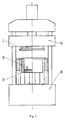
Figure 1 is a schematic structural diagram of an embodiment of the present invention, in which a upper-acting press machine is used. -
Figure 2 is a schematic structural diagram of another embodiment of the present invention, in which a lower-acting press machine is used. -
Figure 3 is a schematic structural diagram of the capsular flexible male mold made of an elastomeric material in the present invention. -
Figure 4 is a schematic structural diagram of the solid flexible male mold made of an elastomeric material in the present invention. -
Figure 5 is an embodiment of special-shaped pulp molded plate with convex part in the present invention. -
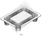
Figure 6 is an embodiment of tray product in the present invention. -
Figure 7 is a schematic diagram of the draining structure of the upper mold and the sealing structure between the upper mold and the enclosing frame. -
Figure 8 is a schematic structural diagram of the telescoping handle for raising the enclosing frame. - In the drawings: 1 - upper mold; 2 - enclosing frame; 3 - lower mold; 4 - plunger-type hydraulic cylinder for supporting the enclosing frame; 5 - press ram of upper-acting press machine; 6 - working platform of upper-acting press machine; 7 - piston-type hydraulic cylinder for supporting and raising/lowering the enclosing frame; 8 - upper beam of lower-acting press machine; 9 - piston rod of main cylinder of lower-acting press machine; 10 - rigid female mold; 11 - capsular sheath; 12 - mold core; 13 - liquid pore passage; 14 - liquid; 15 - mold column; 16 - cavity of syringe; 17 - spring; 18 - solid flexible male mold; 21 - convex part; 25 - plank; 26 - leg; 31 - seal ring and seal groove between the upper mold and the enclosing frame; 32 - guiding water groove; 33 - drain grooves evenly distributed on the surfaces of upper mold; 34 - wire mesh; 35 - telescoping handle; 36 - smooth holes on the enclosing frame; 37 - lower nut of the telescoping handle
- Hereunder the apparatus for producing pulp molded plate in the present invention will be detailed with reference to
Figure 1 , in which it mainly relates to the mounting relation between the three-piece mold and a upper-acting press machine: the main cylinder of the upper-acting press machine is mounted on an upper beam of the press machine, and the piston rod in the main cylinder pushes thepress ram 5 of the press machine to move downwards in the pressing process. Theupper mold 1 of the three-piece mold is fixed to the lower surface of thepress ram 5 by using the T-blocks and bolts and utilizing the T-slots on the lower surface of the press ram, and the upper mold moves up and down with thepress ram 5; the enclosingframe 2 is supported by at least two plunger-typehydraulic cylinders 4 fixed to the workingplatform 6 of the press machine, and it utilizes the plunger-typehydraulic cylinders 4 to provide pressure required for sealing between the enclosing frame and the upper mold; when theupper mold 1 moves down to seal the upper opening of the enclosingframe 2, and pushes the enclosingframe 2 and the plungers of thehydraulic cylinders 4 to move downwards together, the hydraulic oil in the plunger-typehydraulic cylinders 4 will be forced to drain at a preset pressure, so that the pressure required for sealing between the enclosingframe 2 and theupper mold 1 is provided, and theenclosing frame 2 may descend steadily; thelower mold 3 is fixed to the workingplatform 6 of the press machine, and moves in relation to theenclosing frame 2 andupper mold 3, and which is always fitted within the enclosingframe 2. - The upward movement of the enclosing
frame 2 is accomplished by means of jacking action of thehydraulic cylinder 4 or lifting action of theupper mold 1 by a set of slidable rod; in case the enclosingframe 2 is lifted by means of theupper mold 1, the plunger end of thehydraulic cylinder 4 may be separated from the enclosingframe 2, after theenclosing frame 2 is lifted to a specified height, the plunger of thehydraulic cylinder 4 may jack up to fit the enclosingframe 2. - Hereunder the draining structure of the
upper mold 1 and the sealing structure between theupper mold 1 and theenclosing frame 2 will be further detailed with reference toFigure 7 : the enclosingframe 2 is provided with twoseal grooves 31 inlaying seal rings around the opening of the enclosing frame on the contact surfaces with the upper mold, and one or moreguiding water groove 32 is arranged between the seal grooves 312 inlaying seal rings; in a compressed state of theupper mold 1 and enclosingframe 2, thedrain grooves 33 evenly distributed on the working surfaces of theupper mold 1 are extended to above the guidingwater groove 32 and form channels with the guidingwater grooves 32; and the working surfaces of upper mold and lower mold are covered with awire mesh 34 respectively. - Alternatively, the raising action of the enclosing
frame 2 may be accomplished by means of at least two telescopinghandle 35; as shown inFigure 8 , the upper end of the telescoping handle 35 is connected to theupper mold 1 or directly connected to the press ram, when theupper mold 1 returns, the telescoping handle 35 will move synchronously with theupper mold 1; the lower ends of the telescoping handle 35 are slide-fitted into unthreadedholes 36 on theenclosing frame 2; in the case the enclosingframe 2 is supported by at least two plunger-typehydraulic cylinders 4, when theupper mold 1 moves downwards, the telescoping handle 35 will slide down in the unthreaded holes 36 on theenclosing frame 2, till theupper mold 1 is tightly fitted to theenclosing frame 2; when theupper mold 1 returns, the telescoping handle 35 will slide up in the unthreaded holes 36 on theenclosing frame 2, while the enclosingframe 2 doesn't move; when theround nuts 37 on the lower ends of the telescoping handle 35 is contacted with the lower end faces of the unthreaded holes 36, the enclosingframe 2 will be pulled up. After theupper mold 1 returns to the upper limit position and theenclosing frame 2 is pulled up to certain height, at least two plunger-typehydraulic cylinders 4 will jack up, till they support the enclosingframe 2. - Hereunder the apparatus for producing pulp molded plate in the present invention will be further detailed with reference to
Figure 2 , in which it mainly relates to the mounting relation between the three-piece mold and a lower-acting press machine: in the case the press machine is lower-acting, theupper mold 1 is fixed to the lower surface of an upper beam 8 of the press machine, the enclosingframe 2 utilizes two piston-type cylinders 7 fixed to the press machine to accomplish the upward and downward movement and provide a pressure required for sealing between the enclosingframe 2 and the upper mold; thelower mold 3 is fixed to the press ram of the press machine, or, as shown inFigure 2 , thelower mold 3 is directly fixed to the end of apiston rod 9 in the main cylinder of the press machine. - Hereunder the molding method for a capsular flexible male mold made of an elastomeric material in the present invention will be further detailed with reference to
Figure 3 : - A rigid
female mold 10, is mounted on theupper mold 1, and its molding surface is provided with a drain groove and covered with a wire mesh to allow the paper fibers to deposit; - A
capsular sheath 11, made of an elastomeric material, is sleeved on amold core 12 made of a rigid material to form a flexible male mold together with themold core 12; the flexible male mold is inserted into the upper end of amold column 15, which has aspring 17 mounted on the bottom and has a cross section substantially in the same shape as the horizontally projected shape of thecapsular sheath 11 after expansion, themold column 15 is inserted into a hole on thelower mold 3 and which is movable fitted, and dynamic sealed withmold column 15, so as to form asyringe cavity 16 having variable capacity and communicating with thecapsular sheath 11 throughliquid pore passages 13 on themold core 12; the flexible male mold andmold column 15 are coaxial to thefemale mold 10. - For a purpose of simplicity, in this embodiment, the horizontal sections of the
female mold 10,capsular sheath 11, andmold column 15 are in circular shape, and the diameter of the lower segment of themold column 15 is larger than the diameter of the upper segment of themold column 15 slightly, so as to balance the pretension force of thespring 17. - The
syringe cavity 16 is filled withliquid 14; in initial state, themold column 15 is supported at a position allowing a maximum capacity of thesyringe cavity 16 by thespring 17 and the liquid 14 is fully drawn into thesyringe cavity 16; - In the initial state, the
mold column 15 is supported at an upper limit position by the pretension force of the spring, while a certain length of mold column is exposed out the hole on thelower mold 3; when theupper mold 1 andlower mold 3 move towards each other so that enough paper fibers are deposited on the surface of the rigidfemale mold 10 at the convex part, the end of the flexible male mold reaches to the bottom of the rigidfemale mold 10 and begins to squeeze the paper fiber layer there; when the sum of the pressure exerted on the flexible male mold and themold column 15 exceeds the sum of the pretension force of thespring 17 and the seal friction resistance, thespring 17 under themold column 15 is compressed; as the pressure exerted on the flexible male mold and themold column 15 increases, the exposed part of themold column 15 will be reduced gradually, till themold column 15 enters into thelower mold 3 completely; - When the
mold column 15 and thelower mold 3 move towards each other, the liquid 14 in thesyringe cavity 16 will be forced to flow into thecapsular sheath 11, so that thecapsular sheath 11 is expanded to exert a pressure on the deposited paper fiber layer containing high water content around thecapsular sheath 11, so as to accomplish the water squeezing and forming procedure of the convex part. In the reverse process, themold column 15 andlower mold 3 move away from each other in the reversed direction, and the liquid 14 in thecapsular sheath 11 is drawn back into thesyringe cavity 16; as a result, thecapsular sheath 11 will be recovered to its original shape. - In the case the rigid
female mold 10 is mounted on thelower mold 3, the flexible male mold assembly described above is mounted on theupper mold 1 accordingly. - Hereunder the molding method for a solid flexible male mold made of an elastomeric material in the present invention will be further detailed with reference to
Figure 4 : - A rigid
female mold 10, is mounted on theupper mold 1, and its molding surfaces is provide with a drain grooves and covered with a wire mesh to allow the paper fibers to deposit; - A solid flexible
male mold 18, made of an elastomeric material, is mounted on the upper end of amold column 15, which has aspring 17 mounted on the bottom and has a cross section substantially in the same shape as the horizontally projected shape of the solid flexiblemale mold 18 after expansion, themold column 15 is inserted in a hole on thelower mold 3,and which is movable fitted, and dynamic sealed with themold column 15, and the solid flexiblemale mold 18 and themold column 15 are coaxial to thefemale mold 10; - For a purpose of simplicity, in this embodiment, the horizontal sections of the
female mold 10, solid flexiblemale mold 18, andmold column 15 are in circular shape, and the diameter of the lower segment of themold column 15 is larger than the diameter of the upper segment of themold column 15 slightly, so as to balance the pretension force of thespring 17; - In the initial state, the
mold column 15 is supported at an upper limit position by the pretension force of the spring, while a certain length of mold column is exposed out the hole on thelower mold 3; when theupper mold 1 andlower mold 3 move towards each other so that enough paper fibers are deposited on the surface of the rigidfemale mold 10 at the convex part, the end of the solid flexiblemale mold 18 reaches to the bottom of the rigidfemale mold 10 and begins to squeeze the paper fiber layer there; when the sum of the pressure exerted on the solid flexiblemale mold 18 exceeds the sum of the pretension force of thespring 17 and the seal friction resistance, thespring 17 under themold column 15 is compressed; as the pressure exerted on the solid flexiblemale mold 18 increases, the exposed part of themold column 15 will be reduced gradually, till themold column 15 enters into thelower mold 3 completely; - When the
mold column 15 and thelower mold 3 move towards each other, solid flexiblemale mold 18 made of an elastomeric material is deformed by the counter force of the paper fiber layer on the bottom of the rigidfemale mold 10 and the counter force of thespring 17 under themold column 15; the radial dimension thereof increases as reducing of the height (the volume remains constant substantially); therefore, the solid flexiblemale mold 18 exerts a pressure on the deposited paper fiber layer containing high water content around the solid flexiblemale mold 18; in that way, the water squeezing and forming procedure of the convex part is accomplished. - In the case the rigid
female mold 10 is mounted on thelower mold 3, the flexible male mold assembly described above is mounted on theupper mold 1 accordingly. - Hereunder the special-shaped pulp molded plate with convex part in the present invention will be further detailed with reference to
Figure 5 . - The pulp molded plate is a special shape of non-flat, which has at least one
convex part 21 there on, and the ratio of a height H of theconvex part 21 to a minimum aperture d of theconvex part 21 is greater than 0.6;
The maximum density ρmax of the convex part and the minimum density ρmin of the convex part satisfy: (ρmax - ρmin) / ρmax<0.2;
The density of the pulp molded plate is greater than 0.6 g/cm3, and the thickness is 2-20mm thereof; - What an example to a plate purely made of wastepaper pulp by high-pressure molding (>6MPa), the convex part is in a circular truncated cone shape, wherein, H=60mm, d=86mm, H/d=0.7; ρavg=g/cm3, (ρmax - ρmin) / ρmax = (1.03-0.98) / 1.03 = 0.0485; thickness = 7mm.
- Hereunder a high-pressure pulp molded tray producible with the apparatus described above will further detailed with reference to
Figure 6 : - The high-pressure pulp molded tray is a goods tray, which is a special-shaped pulp molded plate having a convex part.
- The tray is made of wastepaper, and formed by high-pressure water squeezing, the density is at 0.6-1.3 g/cm3; the thickness of the plank part is 5-15mm, and the plank 25 and the legs 26 are formed integrally.
- The ratio of the height to the aperture of the legs 26 is greater than 0.8;
Hereunder an example of tray is provided. The plank 25 is in 620×470mm (L×W) dimensions, the tray is in 132mm total height, the ratio of the height to the aperture of the legs 26 is 1, the density is 1 g/cm3, the plank 25 is in thickness of 6mm, and the legs 26 are in thickness of 4mm. - While the present invention has been illustrated and described with reference to some preferred embodiments, the present invention is not limited to these. Those skilled in the art should appreciate that various variations and modifications may be made without departing from the scope of the present invention as defined by the accompanying claims.
Claims (9)
- An apparatus for producing pulp molded plate, comprising a press machine and a three-piece mold, the three-piece mold comprises an upper mold (1), an enclosing frame (2), and a lower mold (3) to form a mold cavity with variable capacity; the molding surface of the upper mold (1) is provided with a drain groove (33) and is covered by a wire mesh (34), the molding surface of the lower mold (3) is provided with a drain groove and/or hole and is covered with a wire mesh, wherein:one of the upper mold (1) and the lower mold (3) is a movable mold, the other is a fixed mold, and the lower mold (3) is always within the enclosing frame (2);the enclosing frame (2) is supported by two or more plunger-type cylinders (4) or piston-type cylinders (7) fixed to the press machine, and which is movable relative to the upper mold (1) and the lower mold (3);the apparatus further comprises two seal grooves (31) and seal rings inlaid in the seal grooves (31), the seal rings are arranged on the contact surface between the opening of the enclosing frame (2) and the upper mold (1), and one or more guiding water grooves (32) are arranged between the two seal grooves (31); in a pressed state of the upper mold (1) and the enclosing frame (2), the drain groove (33) on the molding surface of the upper mold (1) is extended to above the guiding water grooves (32), so as to form a channel with the guiding water groove (32).
- The apparatus for producing pulp molded plate according to claim 1, wherein:the upper mold (1) is a movable mold, which is fixed to the lower surface of a press ram (5) of a upper-acting press machine; the lower mold (3) is a fixed mold, which is fixed to a working platform (6) of the upper-acting press machine;in a initial state, the enclosing frame (2) is supported at the highest position by two or more plunger-type cylinders fixed to the working platform (6) of the press machine;in a working state, the upper mold (1) is driven by the press ram (5) of the press machine to move downwards, contact with the enclosing frame (2), form pressed sealing, and thereby push the enclosing frame (2) to move downwards.
- The apparatus for producing pulp molded plate according to claim 2, wherein:the apparatus further comprises two or more telescoping handles (35) arranged symmetrically, the telescoping handle (35) is inserted in an unthreaded hole (36) of the enclosing frame (2) and is slide-fitted with the unthreaded hole (36); andthe lower end of the telescoping handle (35) passes through a fastener or a stepped shaft, and the outer diameter of the fastener or the stepped shaft is greater than the diameter of the unthreaded hole (36) of the enclosing frame (2), so as to prevent the telescoping handle (35) from pulling out of the unthreaded hole (36); the upper end of the telescoping handle (35) is fixed to the upper mold (1) or the press ram (5) of the press machine.
- The apparatus for producing pulp molded plate according to claim 1, wherein:the lower mold (3) is a movable mold, which is fixed to a press ram (5) of a lower-acting press machine, or which is fixed directly to the piston rod (9) end or plunger end of the main cylinder of the lower-acting press machine; the upper mold (1) is a fixed mold, which is fixed to the lower surface of the upper beam (8) of the lower-acting press machine; an upward and downward movement of the enclosing frame (2) is accomplished by means of two or more piston-type cylinders (7) fixed to the press machine, and thereby a pressing force required for sealing between the enclosing frame (2) and the upper mold (1) is provided.
- The apparatus for producing pulp molded plate according to any of claims 1-4, wherein:the apparatus further comprises a rigid female mold (10) and a flexible male mold matching the rigid female mold (10), both of which are coaxially mounted on the upper mold (1) and the lower mold (3) respectively;the ratio of a height to a minimum aperture of the rigid female mold (10) is greater than 0.6;the flexible male mold is connected to the lower mold (3) or the upper mold (1) via a telescopic mold column (15), which is nested and connected to the flexible male mold; a support spring (17) is mounted on the other end of the mold column (15), the mold column (15) is inserted in the hole on the lower mold (3) or the upper mold (1) arranging the flexible male mold, so as to form a movable fitting and a movable sealing with the hole, and the cross section of the mold column (15) matches the horizontally projected shape of the flexible male mold after expansion;in a initial state, the mold column (15) is supported at the extended limit position by the support spring (17), while a certain length of the mold column (15) is exposed out the hole on the lower mold (3) or the upper mold (1); in a working state, i.e., in the process of that the upper mold (1) and the lower mold (3) move towards each other relatively, the end of the flexible male mold reaches the bottom of the rigid female mold (10) and squeezes the paper fiber layer deposited there, the sealed spaces between the flexible male mold, the support spring (17), the mold column (15) and the hole on the respective mold is compressed, and the flexible male mold is expanded from the initial radial dimension to the maximum radial dimension.
- The apparatus for producing pulp molded plate according to claim 5, wherein:the flexible male mold is constituted by fitting a capsular sheath (11) made of an elastomeric material over a mold core (12) made of a rigid material; the mold core (12) is provided with a interconnected liquid pore passages (13);the mold column (15) is hollow to form a syringe (16) with variable capacity with a receiving hole on the lower mold (3) or upper mold (1); the syringe (16) is communicated with the liquid pore passages (13) of the mold core (12), and is filled with the liquid.
- The apparatus for producing pulp molded plate according to claim 5, wherein:the flexible male mold is a solid element (18) made of an elastomeric material.
- A pulp molded plate producible by the apparatus set forth in claim 5, being in a non-flat special shape, and having at least one convex part, wherein:the ratio of a height to a minimum aperture of the convex part on the pulp molded plate is greater than 0.6;a maximum density ρmax and a minimum density pmin of the convex part satisfy: (ρmax - pmin) / ρmax < 0.2, and in the pulp molded plate, the density is greater than 0.6 g/cm3 and the thickness is 2-20mm.
- The special-shaped pulp molded plate having a convex part according to claim 8, wherein, the plate is in a tray shape formed integrally with plank and leg by high-pressure water squeezing out, the density of the plate is 0.6-1.3g/cm3, and the thickness of the plank is 5-15mm, the ratio of a height to a aperture of the leg is greater than 0.8.
Applications Claiming Priority (2)
| Application Number | Priority Date | Filing Date | Title |
|---|---|---|---|
| CN201010542001.0A CN101985820B (en) | 2010-11-11 | 2010-11-11 | Pulp molded plate and preparation device thereof |
| PCT/CN2011/081666 WO2012062172A1 (en) | 2010-11-11 | 2011-11-02 | Pulp moulded plate and preparation apparatus thereof |
Publications (3)
| Publication Number | Publication Date |
|---|---|
| EP2639352A1 EP2639352A1 (en) | 2013-09-18 |
| EP2639352A4 EP2639352A4 (en) | 2014-08-20 |
| EP2639352B1 true EP2639352B1 (en) | 2016-08-10 |
Family
ID=43710211
Family Applications (1)
| Application Number | Title | Priority Date | Filing Date |
|---|---|---|---|
| EP11839347.9A Not-in-force EP2639352B1 (en) | 2010-11-11 | 2011-11-02 | Pulp moulded plate and preparation apparatus thereof |
Country Status (4)
| Country | Link |
|---|---|
| US (1) | US8795474B2 (en) |
| EP (1) | EP2639352B1 (en) |
| CN (1) | CN101985820B (en) |
| WO (1) | WO2012062172A1 (en) |
Families Citing this family (13)
| Publication number | Priority date | Publication date | Assignee | Title |
|---|---|---|---|---|
| GB201010307D0 (en) * | 2010-06-18 | 2010-08-04 | Greenbottle Ltd | Method apparatus for forming an article from pulped material |
| CN101985820B (en) | 2010-11-11 | 2012-07-04 | 郎旗 | Pulp molded plate and preparation device thereof |
| WO2014193504A1 (en) * | 2013-05-09 | 2014-12-04 | Paul Zhang | Automatic multi-station integrated equipment and method for forming waste-paper-based packaging products |
| US9951478B2 (en) * | 2014-12-12 | 2018-04-24 | Golden Arrow Printing Co., Ltd. | Pulp molding machine and paper-shaped article made thereby |
| US9976262B2 (en) * | 2014-12-12 | 2018-05-22 | Golden Arrow Painting Co., Ltd. | Pulp molding machine, pulp molding process and paper-shaped article made thereby |
| US9556563B1 (en) * | 2016-01-07 | 2017-01-31 | Hui-Ping Yang | Paper pulp molding device |
| CN108505400B (en) * | 2017-02-25 | 2022-04-12 | 郎旗 | Fiber wet forming method and aerospace plane heat insulation tile structure |
| US11421388B1 (en) * | 2019-11-01 | 2022-08-23 | Henry Molded Products, Inc. | Single-walled disposable cooler made of fiber-based material and method of making a single-walled disposable cooler made of fiber-based material |
| CN110924237B (en) * | 2019-12-28 | 2021-07-06 | 广西杰诺智能装备技术股份有限公司 | A kind of pulp molding product forming processing device and its forming processing technology |
| CN111648164B (en) * | 2020-07-06 | 2024-07-12 | 徐允聪 | Modularized hot-press shaping mechanism |
| CN115012254B (en) * | 2022-05-07 | 2024-09-20 | 吴萤 | Paper machine manufacturing method and paper machine |
| CN117265918A (en) * | 2023-11-08 | 2023-12-22 | 山东智沃机械设备有限公司 | A wet pressing preparation method for high-pressure gas extrusion molding of plant fiber containers |
| CN119411431B (en) * | 2025-01-07 | 2025-03-25 | 厦门中乾机械有限公司 | Forming mold and paper dinner plate forming machine |
Family Cites Families (13)
| Publication number | Priority date | Publication date | Assignee | Title |
|---|---|---|---|---|
| GB720915A (en) * | 1953-04-13 | 1954-12-29 | Werner Von Seydlitz | Improvements in and relating to the production of porous slabs and other bodies fromfibrous materials, particularly from peat |
| US2754729A (en) * | 1953-09-15 | 1956-07-17 | Keyes Fibre Co | Molding of perforated pulp articles |
| US2922476A (en) * | 1954-04-10 | 1960-01-26 | Koxvold Leif Fras | Apparatus for producing hollow articles by dewatering fiber pulp |
| US2777367A (en) * | 1954-06-02 | 1957-01-15 | Ednell Daniel Fredrik | Method for producing cones from a fibrous pulp suspension |
| FR2266591B1 (en) * | 1974-04-04 | 1976-10-08 | Zelant Gazuit | |
| US5064504A (en) * | 1989-03-14 | 1991-11-12 | Shetka Stanley J | Pulp molding press |
| GB2330552B (en) * | 1997-10-25 | 2002-08-14 | Px Technologies Ltd | Improvements relating to forming machines |
| CN2663497Y (en) * | 2003-06-25 | 2004-12-15 | 姜陆平 | Hot pressing shaping mechanism for paper mould products |
| CN2647905Y (en) * | 2003-06-25 | 2004-10-13 | 姜陆平 | Working mould table for paper pulp model equipment |
| WO2007022695A1 (en) * | 2005-08-22 | 2007-03-01 | Qi Lang | A method for manufacturing pulp molding plate and a mould used therein |
| CN101070688B (en) * | 2005-08-22 | 2014-08-20 | 郎旗 | Method for preparing paper-pulp moulded board and mould there used |
| CN101634124A (en) * | 2008-07-22 | 2010-01-27 | 郎旗 | Method for preparing special pulp moulding plate with convex part and mould |
| CN101985820B (en) * | 2010-11-11 | 2012-07-04 | 郎旗 | Pulp molded plate and preparation device thereof |
-
2010
- 2010-11-11 CN CN201010542001.0A patent/CN101985820B/en not_active Expired - Fee Related
-
2011
- 2011-11-02 US US13/883,998 patent/US8795474B2/en not_active Expired - Fee Related
- 2011-11-02 WO PCT/CN2011/081666 patent/WO2012062172A1/en not_active Ceased
- 2011-11-02 EP EP11839347.9A patent/EP2639352B1/en not_active Not-in-force
Also Published As
| Publication number | Publication date |
|---|---|
| EP2639352A1 (en) | 2013-09-18 |
| US20130228301A1 (en) | 2013-09-05 |
| CN101985820B (en) | 2012-07-04 |
| WO2012062172A1 (en) | 2012-05-18 |
| US8795474B2 (en) | 2014-08-05 |
| CN101985820A (en) | 2011-03-16 |
| EP2639352A4 (en) | 2014-08-20 |
Similar Documents
| Publication | Publication Date | Title |
|---|---|---|
| US8795474B2 (en) | Pulp moulded plate and preparation apparatus thereof | |
| CN112719265A (en) | Titanium electrode press floating pressing device and method for pressing titanium electrode block | |
| CN218983182U (en) | A manual two-way pressure tube mold | |
| CN206230656U (en) | A kind of equipment for press ceramic adobe | |
| CN204109412U (en) | Preforming device | |
| CN221021526U (en) | Magnesia carbon brick production forming device | |
| CN204519129U (en) | Tea cake extrusion forming device | |
| CN203505465U (en) | Press device for brick tea | |
| CN206251813U (en) | A kind of semi-automatic moon cake press | |
| CN101634124A (en) | Method for preparing special pulp moulding plate with convex part and mould | |
| CN209599708U (en) | A kind of polytetrafluoroethylene (PTFE) materials in the tube pressure setting | |
| CN216912095U (en) | Powder metallurgy spare embossing mold utensil structure | |
| CN215434163U (en) | Wall building block forming machine | |
| CN210061504U (en) | A vertical hydraulic extruder | |
| CN111618981A (en) | A powder briquetting die and powder briquetting machine | |
| CN203391080U (en) | Upper die extrusion drainage device of high pressure forming machine | |
| US1005706A (en) | Apparatus for making asbestos-cement slabs and the like. | |
| CN218693872U (en) | Four-column type quick powder hydraulic press | |
| CN111823632A (en) | A compression molding device and compression molding method for cup-shaped powder products | |
| CN209599939U (en) | A kind of press machine with fixed structure porous and easy demoulding | |
| WO2009089693A1 (en) | Bidirectional pressing method and apparatus for forming plant fiber pallet | |
| JPS6213765Y2 (en) | ||
| CN206882783U (en) | New dry model iso-static pressure shaping machine | |
| CN204519134U (en) | Tea cake single lead screw ex truding briquetting machine | |
| CN219125274U (en) | Fu brick tea pressing machine |
Legal Events
| Date | Code | Title | Description |
|---|---|---|---|
| PUAI | Public reference made under article 153(3) epc to a published international application that has entered the european phase |
Free format text: ORIGINAL CODE: 0009012 |
|
| 17P | Request for examination filed |
Effective date: 20130611 |
|
| AK | Designated contracting states |
Kind code of ref document: A1 Designated state(s): AL AT BE BG CH CY CZ DE DK EE ES FI FR GB GR HR HU IE IS IT LI LT LU LV MC MK MT NL NO PL PT RO RS SE SI SK SM TR |
|
| DAX | Request for extension of the european patent (deleted) | ||
| A4 | Supplementary search report drawn up and despatched |
Effective date: 20140723 |
|
| RIC1 | Information provided on ipc code assigned before grant |
Ipc: D21J 3/00 20060101AFI20140717BHEP |
|
| 17Q | First examination report despatched |
Effective date: 20150724 |
|
| REG | Reference to a national code |
Ref country code: DE Ref legal event code: R079 Ref document number: 602011029159 Country of ref document: DE Free format text: PREVIOUS MAIN CLASS: D21J0001040000 Ipc: D21J0003100000 |
|
| GRAP | Despatch of communication of intention to grant a patent |
Free format text: ORIGINAL CODE: EPIDOSNIGR1 |
|
| RIC1 | Information provided on ipc code assigned before grant |
Ipc: D21J 3/00 20060101ALI20160127BHEP Ipc: D21J 3/10 20060101AFI20160127BHEP Ipc: D21J 7/00 20060101ALI20160127BHEP |
|
| INTG | Intention to grant announced |
Effective date: 20160217 |
|
| GRAS | Grant fee paid |
Free format text: ORIGINAL CODE: EPIDOSNIGR3 |
|
| GRAA | (expected) grant |
Free format text: ORIGINAL CODE: 0009210 |
|
| AK | Designated contracting states |
Kind code of ref document: B1 Designated state(s): AL AT BE BG CH CY CZ DE DK EE ES FI FR GB GR HR HU IE IS IT LI LT LU LV MC MK MT NL NO PL PT RO RS SE SI SK SM TR |
|
| REG | Reference to a national code |
Ref country code: GB Ref legal event code: FG4D |
|
| REG | Reference to a national code |
Ref country code: CH Ref legal event code: EP Ref country code: AT Ref legal event code: REF Ref document number: 819189 Country of ref document: AT Kind code of ref document: T Effective date: 20160815 |
|
| REG | Reference to a national code |
Ref country code: IE Ref legal event code: FG4D |
|
| REG | Reference to a national code |
Ref country code: DE Ref legal event code: R096 Ref document number: 602011029159 Country of ref document: DE |
|
| REG | Reference to a national code |
Ref country code: FR Ref legal event code: PLFP Year of fee payment: 6 |
|
| REG | Reference to a national code |
Ref country code: LT Ref legal event code: MG4D |
|
| REG | Reference to a national code |
Ref country code: NL Ref legal event code: MP Effective date: 20160810 |
|
| REG | Reference to a national code |
Ref country code: AT Ref legal event code: MK05 Ref document number: 819189 Country of ref document: AT Kind code of ref document: T Effective date: 20160810 |
|
| PG25 | Lapsed in a contracting state [announced via postgrant information from national office to epo] |
Ref country code: NL Free format text: LAPSE BECAUSE OF FAILURE TO SUBMIT A TRANSLATION OF THE DESCRIPTION OR TO PAY THE FEE WITHIN THE PRESCRIBED TIME-LIMIT Effective date: 20160810 Ref country code: LT Free format text: LAPSE BECAUSE OF FAILURE TO SUBMIT A TRANSLATION OF THE DESCRIPTION OR TO PAY THE FEE WITHIN THE PRESCRIBED TIME-LIMIT Effective date: 20160810 Ref country code: IS Free format text: LAPSE BECAUSE OF FAILURE TO SUBMIT A TRANSLATION OF THE DESCRIPTION OR TO PAY THE FEE WITHIN THE PRESCRIBED TIME-LIMIT Effective date: 20161210 Ref country code: RS Free format text: LAPSE BECAUSE OF FAILURE TO SUBMIT A TRANSLATION OF THE DESCRIPTION OR TO PAY THE FEE WITHIN THE PRESCRIBED TIME-LIMIT Effective date: 20160810 Ref country code: NO Free format text: LAPSE BECAUSE OF FAILURE TO SUBMIT A TRANSLATION OF THE DESCRIPTION OR TO PAY THE FEE WITHIN THE PRESCRIBED TIME-LIMIT Effective date: 20161110 Ref country code: FI Free format text: LAPSE BECAUSE OF FAILURE TO SUBMIT A TRANSLATION OF THE DESCRIPTION OR TO PAY THE FEE WITHIN THE PRESCRIBED TIME-LIMIT Effective date: 20160810 Ref country code: HR Free format text: LAPSE BECAUSE OF FAILURE TO SUBMIT A TRANSLATION OF THE DESCRIPTION OR TO PAY THE FEE WITHIN THE PRESCRIBED TIME-LIMIT Effective date: 20160810 Ref country code: IT Free format text: LAPSE BECAUSE OF FAILURE TO SUBMIT A TRANSLATION OF THE DESCRIPTION OR TO PAY THE FEE WITHIN THE PRESCRIBED TIME-LIMIT Effective date: 20160810 |
|
| PG25 | Lapsed in a contracting state [announced via postgrant information from national office to epo] |
Ref country code: PL Free format text: LAPSE BECAUSE OF FAILURE TO SUBMIT A TRANSLATION OF THE DESCRIPTION OR TO PAY THE FEE WITHIN THE PRESCRIBED TIME-LIMIT Effective date: 20160810 Ref country code: SE Free format text: LAPSE BECAUSE OF FAILURE TO SUBMIT A TRANSLATION OF THE DESCRIPTION OR TO PAY THE FEE WITHIN THE PRESCRIBED TIME-LIMIT Effective date: 20160810 Ref country code: ES Free format text: LAPSE BECAUSE OF FAILURE TO SUBMIT A TRANSLATION OF THE DESCRIPTION OR TO PAY THE FEE WITHIN THE PRESCRIBED TIME-LIMIT Effective date: 20160810 Ref country code: BE Free format text: LAPSE BECAUSE OF NON-PAYMENT OF DUE FEES Effective date: 20161130 Ref country code: AT Free format text: LAPSE BECAUSE OF FAILURE TO SUBMIT A TRANSLATION OF THE DESCRIPTION OR TO PAY THE FEE WITHIN THE PRESCRIBED TIME-LIMIT Effective date: 20160810 Ref country code: GR Free format text: LAPSE BECAUSE OF FAILURE TO SUBMIT A TRANSLATION OF THE DESCRIPTION OR TO PAY THE FEE WITHIN THE PRESCRIBED TIME-LIMIT Effective date: 20161111 Ref country code: PT Free format text: LAPSE BECAUSE OF FAILURE TO SUBMIT A TRANSLATION OF THE DESCRIPTION OR TO PAY THE FEE WITHIN THE PRESCRIBED TIME-LIMIT Effective date: 20161212 Ref country code: LV Free format text: LAPSE BECAUSE OF FAILURE TO SUBMIT A TRANSLATION OF THE DESCRIPTION OR TO PAY THE FEE WITHIN THE PRESCRIBED TIME-LIMIT Effective date: 20160810 |
|
| PG25 | Lapsed in a contracting state [announced via postgrant information from national office to epo] |
Ref country code: RO Free format text: LAPSE BECAUSE OF FAILURE TO SUBMIT A TRANSLATION OF THE DESCRIPTION OR TO PAY THE FEE WITHIN THE PRESCRIBED TIME-LIMIT Effective date: 20160810 Ref country code: EE Free format text: LAPSE BECAUSE OF FAILURE TO SUBMIT A TRANSLATION OF THE DESCRIPTION OR TO PAY THE FEE WITHIN THE PRESCRIBED TIME-LIMIT Effective date: 20160810 |
|
| REG | Reference to a national code |
Ref country code: DE Ref legal event code: R097 Ref document number: 602011029159 Country of ref document: DE |
|
| PG25 | Lapsed in a contracting state [announced via postgrant information from national office to epo] |
Ref country code: CZ Free format text: LAPSE BECAUSE OF FAILURE TO SUBMIT A TRANSLATION OF THE DESCRIPTION OR TO PAY THE FEE WITHIN THE PRESCRIBED TIME-LIMIT Effective date: 20160810 Ref country code: DK Free format text: LAPSE BECAUSE OF FAILURE TO SUBMIT A TRANSLATION OF THE DESCRIPTION OR TO PAY THE FEE WITHIN THE PRESCRIBED TIME-LIMIT Effective date: 20160810 Ref country code: BE Free format text: LAPSE BECAUSE OF FAILURE TO SUBMIT A TRANSLATION OF THE DESCRIPTION OR TO PAY THE FEE WITHIN THE PRESCRIBED TIME-LIMIT Effective date: 20160810 Ref country code: SM Free format text: LAPSE BECAUSE OF FAILURE TO SUBMIT A TRANSLATION OF THE DESCRIPTION OR TO PAY THE FEE WITHIN THE PRESCRIBED TIME-LIMIT Effective date: 20160810 Ref country code: SK Free format text: LAPSE BECAUSE OF FAILURE TO SUBMIT A TRANSLATION OF THE DESCRIPTION OR TO PAY THE FEE WITHIN THE PRESCRIBED TIME-LIMIT Effective date: 20160810 Ref country code: BG Free format text: LAPSE BECAUSE OF FAILURE TO SUBMIT A TRANSLATION OF THE DESCRIPTION OR TO PAY THE FEE WITHIN THE PRESCRIBED TIME-LIMIT Effective date: 20161110 |
|
| PLBE | No opposition filed within time limit |
Free format text: ORIGINAL CODE: 0009261 |
|
| STAA | Information on the status of an ep patent application or granted ep patent |
Free format text: STATUS: NO OPPOSITION FILED WITHIN TIME LIMIT |
|
| REG | Reference to a national code |
Ref country code: CH Ref legal event code: PL |
|
| 26N | No opposition filed |
Effective date: 20170511 |
|
| PG25 | Lapsed in a contracting state [announced via postgrant information from national office to epo] |
Ref country code: LI Free format text: LAPSE BECAUSE OF NON-PAYMENT OF DUE FEES Effective date: 20161130 Ref country code: CH Free format text: LAPSE BECAUSE OF NON-PAYMENT OF DUE FEES Effective date: 20161130 |
|
| REG | Reference to a national code |
Ref country code: IE Ref legal event code: MM4A |
|
| PG25 | Lapsed in a contracting state [announced via postgrant information from national office to epo] |
Ref country code: SI Free format text: LAPSE BECAUSE OF FAILURE TO SUBMIT A TRANSLATION OF THE DESCRIPTION OR TO PAY THE FEE WITHIN THE PRESCRIBED TIME-LIMIT Effective date: 20160810 |
|
| PG25 | Lapsed in a contracting state [announced via postgrant information from national office to epo] |
Ref country code: LU Free format text: LAPSE BECAUSE OF NON-PAYMENT OF DUE FEES Effective date: 20161130 |
|
| REG | Reference to a national code |
Ref country code: FR Ref legal event code: PLFP Year of fee payment: 7 |
|
| PG25 | Lapsed in a contracting state [announced via postgrant information from national office to epo] |
Ref country code: IE Free format text: LAPSE BECAUSE OF NON-PAYMENT OF DUE FEES Effective date: 20161102 |
|
| PG25 | Lapsed in a contracting state [announced via postgrant information from national office to epo] |
Ref country code: CY Free format text: LAPSE BECAUSE OF FAILURE TO SUBMIT A TRANSLATION OF THE DESCRIPTION OR TO PAY THE FEE WITHIN THE PRESCRIBED TIME-LIMIT Effective date: 20160810 Ref country code: HU Free format text: LAPSE BECAUSE OF FAILURE TO SUBMIT A TRANSLATION OF THE DESCRIPTION OR TO PAY THE FEE WITHIN THE PRESCRIBED TIME-LIMIT; INVALID AB INITIO Effective date: 20111102 |
|
| PG25 | Lapsed in a contracting state [announced via postgrant information from national office to epo] |
Ref country code: MC Free format text: LAPSE BECAUSE OF FAILURE TO SUBMIT A TRANSLATION OF THE DESCRIPTION OR TO PAY THE FEE WITHIN THE PRESCRIBED TIME-LIMIT Effective date: 20160810 Ref country code: MK Free format text: LAPSE BECAUSE OF FAILURE TO SUBMIT A TRANSLATION OF THE DESCRIPTION OR TO PAY THE FEE WITHIN THE PRESCRIBED TIME-LIMIT Effective date: 20160810 |
|
| PG25 | Lapsed in a contracting state [announced via postgrant information from national office to epo] |
Ref country code: MT Free format text: LAPSE BECAUSE OF NON-PAYMENT OF DUE FEES Effective date: 20161102 |
|
| PG25 | Lapsed in a contracting state [announced via postgrant information from national office to epo] |
Ref country code: AL Free format text: LAPSE BECAUSE OF FAILURE TO SUBMIT A TRANSLATION OF THE DESCRIPTION OR TO PAY THE FEE WITHIN THE PRESCRIBED TIME-LIMIT Effective date: 20160810 Ref country code: TR Free format text: LAPSE BECAUSE OF FAILURE TO SUBMIT A TRANSLATION OF THE DESCRIPTION OR TO PAY THE FEE WITHIN THE PRESCRIBED TIME-LIMIT Effective date: 20160810 |
|
| PGFP | Annual fee paid to national office [announced via postgrant information from national office to epo] |
Ref country code: GB Payment date: 20181128 Year of fee payment: 8 Ref country code: FR Payment date: 20181130 Year of fee payment: 8 |
|
| PGFP | Annual fee paid to national office [announced via postgrant information from national office to epo] |
Ref country code: DE Payment date: 20190124 Year of fee payment: 8 |
|
| REG | Reference to a national code |
Ref country code: DE Ref legal event code: R119 Ref document number: 602011029159 Country of ref document: DE |
|
| GBPC | Gb: european patent ceased through non-payment of renewal fee |
Effective date: 20191102 |
|
| PG25 | Lapsed in a contracting state [announced via postgrant information from national office to epo] |
Ref country code: DE Free format text: LAPSE BECAUSE OF NON-PAYMENT OF DUE FEES Effective date: 20200603 Ref country code: GB Free format text: LAPSE BECAUSE OF NON-PAYMENT OF DUE FEES Effective date: 20191102 Ref country code: FR Free format text: LAPSE BECAUSE OF NON-PAYMENT OF DUE FEES Effective date: 20191130 |