EP2639132A1 - Floor structure of railroad vehicle - Google Patents
Floor structure of railroad vehicle Download PDFInfo
- Publication number
- EP2639132A1 EP2639132A1 EP11839628.2A EP11839628A EP2639132A1 EP 2639132 A1 EP2639132 A1 EP 2639132A1 EP 11839628 A EP11839628 A EP 11839628A EP 2639132 A1 EP2639132 A1 EP 2639132A1
- Authority
- EP
- European Patent Office
- Prior art keywords
- metal plate
- floor
- heat insulating
- insulating material
- railcar
- Prior art date
- Legal status (The legal status is an assumption and is not a legal conclusion. Google has not performed a legal analysis and makes no representation as to the accuracy of the status listed.)
- Withdrawn
Links
Images






Classifications
-
- B—PERFORMING OPERATIONS; TRANSPORTING
- B61—RAILWAYS
- B61D—BODY DETAILS OR KINDS OF RAILWAY VEHICLES
- B61D17/00—Construction details of vehicle bodies
- B61D17/04—Construction details of vehicle bodies with bodies of metal; with composite, e.g. metal and wood body structures
- B61D17/10—Floors
-
- B—PERFORMING OPERATIONS; TRANSPORTING
- B61—RAILWAYS
- B61D—BODY DETAILS OR KINDS OF RAILWAY VEHICLES
- B61D17/00—Construction details of vehicle bodies
- B61D17/04—Construction details of vehicle bodies with bodies of metal; with composite, e.g. metal and wood body structures
- B61D17/18—Internal lining, e.g. insulating
-
- B—PERFORMING OPERATIONS; TRANSPORTING
- B61—RAILWAYS
- B61F—RAIL VEHICLE SUSPENSIONS, e.g. UNDERFRAMES, BOGIES OR ARRANGEMENTS OF WHEEL AXLES; RAIL VEHICLES FOR USE ON TRACKS OF DIFFERENT WIDTH; PREVENTING DERAILING OF RAIL VEHICLES; WHEEL GUARDS, OBSTRUCTION REMOVERS OR THE LIKE FOR RAIL VEHICLES
- B61F1/00—Underframes
- B61F1/08—Details
Definitions
- the present invention relates to a floor structure of a railcar.
- Patent Literature 1 discloses a floor structure wherein a highly-fire-resistant and incombustible heat insulating material made of glass wool and a highly-heat-insulating and moisture-retaining heat insulating material made of ceramic fiber are combined as a heat insulating material in order to improve the heat insulating property and the fire resistance.
- Patent Literature 2 discloses a floor structure of a laminated structure having an upper layer containing hydroxide, a middle layer providing structural strength, and a lower layer covering a lower surface, wherein a heat insulating material is formed between the middle layer and the lower layer.
- heat resistance of a floor can be improved by complicating the floor structure and increasing thickness of the heat insulating material.
- length (thickness) in the up and down direction of the floor structure is restricted.
- An object of the present invention is to provide a floor structure of a railcar in which even when thickness of the floor structure is strictly restricted, thickness of a heat insulating material can be reduced while having predetermined heat resistance.
- a floor structure of a railcar includes a underframe having a pair of side sills extending in a railcar longitudinal direction and a cross beam arranged between the side sills and extending in a railcar width direction, a structural floor provided on an upper surface of the underframe, and a first heat insulating material arranged on a lower side of the structural floor via an air layer for the structural floor.
- the structural floor is covered with the first heat insulating material via the air layer.
- a heat insulating effect is added by the air layer and a heat insulating effect for the entire structure is improved, thickness in the up and down direction of both the air layer and the first heat insulating material can be shortened.
- a heat insulating structure on the lower side of the structural floor can be downsized, so that various fixtures are easily arranged under the floor, for example, a large underfloor equipment can be attached.
- the floor structure of the railcar can be provided in which even when thickness of the floor structure is strictly restricted, thickness of the heat insulating material can be reduced while having predetermined heat resistance.
- Fig. 1 is a schematic sectional view of a railcar provided with a floor structure according to the present invention.
- a underframe 1 is provided in a lowermost part of a carbody shell of the railcar.
- the underframe 1 has a pair of side sills 2 arranged in the rail direction, that is, in the railcar longitudinal direction (Y direction), and a plurality of cross beams 3 for combining the pair of side sills 2 in the cross sleeper direction, that is, in railcar width direction (Z direction).
- Fig. 2 is a schematic perspective view showing the side sills 2 and the cross beams 3.
- the cross beams 3 are provided at a pitch of 600 mm to 1,000 mm in the Y direction.
- a plurality of piping holes 31 into which electric wires, air piping, and the like hereinafter, simply referred to as the "electric wire and piping etc." are inserted are provided in line in the Z direction.
- a structural floor 4 serving as an air-tight floor is provided on the underframe 1, and a plurality of floor receiving members 5 extending in the Y direction stand on the structural floor 4 at an interval in the Z direction.
- the floor receiving members 5 support a passenger cabin floor 6 forming a floor of a passenger cabin S on the upper side spaced from the structural floor 4 by a fixed distance.
- Seats 7 on which passengers are seated are provided on the passenger cabin floor 6.
- Fig. 3 is a sectional view taken along line III-III of Fig. 1 .
- the cross beams 3 have a substantially I shape section.
- rectangular suspending groove portions 3a whose lower end openings are narrowed down are integrally formed. Head parts of a plurality of suspended bolts 8 are inserted into the suspending groove portions 3a.
- An underfloor equipement 10 is supported by the suspended bolts 8 and nuts 8a via brackets 9.
- Fig. 4 is an enlarged view of a part of the structural floor 4 where no cross beams 3 are provided in Fig. 3 .
- a first heat insulating material 42a is provided via a space (air layer 41a).
- An upper surface of the first heat insulating material 42a is covered with a second metal plate 43a and a lower surface of the first heat insulating material 42a is covered with a first metal plate 43b.
- the first heat insulating material 42a is preferably formed by using glass fiber or ceramic fiber including alumina fiber.
- the second metal plate 43a and the first metal plate 43b are preferably stainless steel. Surface finish such as polishing processing is preferably performed to outer surfaces of the second metal plate 43a and the first metal plate 43b.
- Thickness D1 in the up and down direction of the air layer 41a is smaller than thickness D2 in the up and down direction of the first heat insulating material 42a. Specifically, the thickness D1 is about 1/3 of the thickness D2.
- Fig. 5 is an enlarged view of a part of the cross beam 3 where the underfloor equipement 10 is not suspended in Fig. 3 .
- a lower part of the cross beam 3 and at least a part of a side part, that is, a web 3b and the suspending groove portion 3a of the cross beam 3 are covered with a second heat insulating material 42b.
- An outer surface of the second heat insulating material 42b is covered with a third metal plate 43c having a U shape section.
- An upper surface of the cross beam 3 is attached to the structural floor 4, and upper side parts of the cross beam 3 are covered with the air layer 41a or the first heat insulating material 42a.
- the third metal plate 43c is supported by the cross beam 3 via the second heat insulating material 42b, and the first metal plate 43b and the third metal plate 43c are not in contact with each other.
- Fig. 6 is an enlarged view of a part of the cross beam 3 where the underfloor equipement 10 is suspended in Fig. 3 .
- the web 3b and the suspending groove portion 3a of the cross beam 3 are covered with the second heat insulating material 42b.
- the outer surface of the second heat insulating material 42b is covered with the third metal plate 43c.
- the third metal plate 43c is supported by the suspended bolts 8, and the first metal plate 43b and the third metal plate 43c are not in contact with each other.
- a collar 32 is provided on the lower side of the cross beam 3 and on the upper side of the third metal plate 43c, and oscillation of the suspended bolts 8 is suppressed by the collar 32.
- Fig. 7 is a view showing a heat resistant structure of the part of the cross beam 3 where the underfloor equipement 10 is suspended, the heat resistant structure being different from Fig. 6 (modified example).
- the second heat insulating material 42b is formed so as to have a U shape section, an outside surface is covered with the third metal plate 43c, and an inside surface is covered with a fourth metal plate 43d.
- the air layer 41b is provided between the fourth metal plate 43d on the inner side and the cross beam 3.
- the third metal plate 43c and the fourth metal plate 43d covering the second heat insulating material 42b are supported by the suspended bolts 8, the first metal plate 43b and the third metal plate 43c are not in contact with each other, and the first metal plate 43b and the fourth metal plate 43d are not in contact with each other.
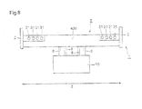
- Fig. 8 is a front view in the Y direction of the cross beam 3 covered with the second heat insulating material 42b.
- the electric wire and piping etc. are actually inserted into parts excluding a substantially center part in the Z direction, for example, both ends in the Z direction. Therefore, excluding the parts of several piping holes 31 in both the ends in the Z direction, the cross beam 3 is covered with the second heat insulating material 42b which is covered with the third metal plate 43c.
- the second heat insulating material 42b is preferably the same as the first heat insulating material 42a.
- the third metal plate 43c and the fourth metal plate 43d are preferably the same as the second metal plate 43a and the first metal plate 43b.
- Fig. 9 is a view in which the first metal plate 43b covering the lower surface of the first heat insulating material 42a is seen from the lower side.
- Fig. 10 is a sectional view taken along line X-X of Fig. 9
- Fig. 11 is a partially enlarged view of Fig. 10
- Fig. 12 is a sectional view taken along line XII-XII of Fig. 9
- Fig. 13 is a partially enlarged view of Fig. 12 .
- the first metal plate 43b in order to prevent downward deflection of the first metal plate 43b, between the cross beams 3 in the Y direction, the first metal plate 43b is formed by combining two first metal plates 43b1, 43b2 in a substantial center in the Y direction.
- plate-shaped first plate members 432 are attached by welding.
- first support members 433 formed in a Z shape when seen in the Z direction are attached by welding.
- the ends of the first metal plate 43b1 and the first metal plate 43b2 are supported by the cross beams 3.
- the first metal plate 43b1 and the first metal plate 43b2 are brought into direct contact with flame.
- the first plate members 432 are attached to the cross beams 3 on the upper side of the first metal plate 43b1 and the first metal plate 43b2.
- the first metal plate 43b1 and the first metal plate 43b2 extend toward the cross beams 3 on the lower side of the first plate members 432. With such a configuration, direct contact of the first plate members 432 with the flame can be prevented.
- the plurality of first plate members 432 are provided at an interval in the Z direction.
- a contact area of the first plate members 432 and the cross beams 3 is reduced.
- a heat transmission amount from the first metal plates 43b1, 43b2 to the cross beams 3 is reduced. Therefore, a temperature increase of the cross beams 3 can be reduced.
- Fig. 11 shows a detail of a combining part of the first metal plate 43b1 and the first metal plate 43b2.
- a second plate member 434 extending in the substantially vertical direction from the structural floor 4 is attached by welding.
- the second plate member 434 and a second support member 435 formed in a substantially L shape when seen in the Z direction are fastened by a bolt 436 and a nut 436a.
- the second support member 435, the first metal plate 43b1, and the first metal plate 43b2 are fastened by a bolt 437 and a nut 437a.
- the second support member 435 a part to be fastened together with the second plate member by the bolt 436 and the nut 436a is called a first fastened portion, and a part to be fastened together with the first metal plate 43b1 and the first metal plate 43b2 by the bolt 437 and the nut 437a is called a second fastened portion.
- the second plate member 434 is formed in a substantially L shape in Fig. 11 , the shape is not limited thereto, and it may take any shape as long as it is fastened to the second plate member 434 and to the first metal plates 43b1, 43b2.
- one end of the divided first metal plates 43b1, 43b2 is inserted between the cross beam 3 and the first plate member 432 and the other end is fastened to the structural floor 4 by the bolt 436 and the bolt 437 via the second support member 435. Therefore, even if, for example, the structural floor 4 is an aluminum alloy and the first metal plate 43b is stainless steel, that is, the structural floor 4 and the first metal plate 43b are made of different types of materials from each other, the first metal plate 43b can be supported by the structural floor 4 by adopting the above attachment structure.
- the first metal plate 43b is divided into two of the first metal plate 43b1 and the first metal plate 43b2.
- stiffeners 438 having an L shape section are preferably attached to upper surfaces of the first metal plates 43b1, 43b2 by welding.
- the plurality of stiffeners 438 extend in the Y direction and are provided at an interval in the Z direction.
- third support members 439 supporting the structural floor 4 are provided on the lower side of the structural floor 4 and on an upper surface of the second metal plate 43a covering the upper surface of the first heat insulating material 42a.
- the plurality of third support members 439 are provided at an interval in the Z direction and the Y direction.
- the underfloor equipement 10 is generally suspended in a center part in the Z direction of the cross beam 3.
- the electric wire and piping etc. are actually inserted into the parts excluding the substantially center part in the Z direction, for example, both the ends in the Z direction.
- Fig. 14 is a schematic perspective view of the floor structure for reducing the bearing load of the cross beams 3.
- the floor receiving members 5 extending in the Y direction are provided on the structural floor 4 at an interval in the Z direction.
- Floor receiving members 5a provided in the substantially center part in the Z direction excluding both the ends in the Z direction are welded and fixed to the structural floor 4 over the entire length in the Y direction of the floor receiving members 5a.
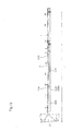
- Figs. 15 and 16 are schematic front views of the cross beams 3 each showing a state before the underfloor fire and after the underfloor fire in the floor structure of Fig. 14 .
- the third metal plate 43c covering the second heat insulating material 42b is deleted.
- the underfloor equipement 10 is suspended in the center part in the Z direction of the cross beams 3 by the suspended bolts 8.
- the cross beams 3 are covered with the second heat insulating material 42b excluding the parts of the piping holes 31 in both the ends in the Z direction of the cross beams 3.
- the temperature is increased in the parts of the piping holes 31 in both the ends in the Z direction of the cross beams 3, the parts not being covered with the second heat insulating material 42b, so that the cross beams 3 are easily deformed.
- the cross beams 3 are deflected downward by a load G of the underfloor equipement 10.
- the upper parts of the cross beams 3 are attached to the structural floor 4, and the floor receiving members 5 are attached to an upper part of the structural floor 4 so as to couple the cross beams 3.
- the floor receiving members 5a in the substantially center part in the Z direction where the underfloor equipement 10 is suspended are fixed to the structural floor 4 over the entire length in the Y direction of the floor receiving members 5a.
- the floor receiving members 5a may be fixed to the structural floor 4 by welding or the floor receiving members 5a and the structural floor 4 may be integrated. Therefore, as shown in Fig. 14 , the floor receiving members 5a can bear a part of the load G of the underfloor equipement 10. That is, a part of the load G of the underfloor equipement 10 is transmitted in the F1 direction and the F2 direction which are parallel to the Y direction through the floor receiving members 5a.
- the structural floor 4 is covered with the first heat insulating material 42a via the air layer 41a.
- thickness in the up and down direction (D1 + D2) of both the air layer 41a and the first heat insulating material 42a can be shortened.
- a heat insulating structure on the lower side of the structural floor 4 can be downsized, so that the large underfloor equipement 10 can be attached.
- a heat transmission mode is classified into heat conduction, heat transfer, and heat emission (radiation).
- the heat conduction and the radiation are major.
- a relationship between the heat conduction and the radiation differs depending on a temperature.
- the radiation is dominant over the heat conduction at a high temperature (500°C or more) and the heat conduction is dominant over the radiation at a low temperature (500°C or less).
- a heat conduction property is lower in the air layer 41a than the first heat insulating material 42a.
- a property for blocking the radiation is higher in the first heat insulating material 42a than the air layer 41a.
- the thickness in the up and down direction of both the air layer 41a and the first heat insulating material 42a (hereinafter, referred to as the "thickness") can be thinnest.
- a temperature of the flame is about 1,000°C
- a temperature of the lower surface of the first heat insulating material 42a becomes about 800°C.
- the thickness D1 of the air layer 41a is preferably smaller than the thickness D2 of the first heat insulating material 42a. Further, the thickness D1 of the air layer 41a is preferably about 1/3 of the thickness D2 of the first heat insulating material 42a.
- FIG. 17 is a graph showing a temperature ratio between the temperature of the structural floor 4 and an in-furnace temperature (corresponding to the temperature of the underfloor fire) with respect to the thickness of the first heat insulating material 42a in a case where the sum of the thickness D1 of the air layer 41a and the thickness D2 of the first heat insulating material 42a is 20 mm. From Fig. 17 , for example when the sum of the thickness D1 of the air layer 41a and the thickness D2 of the first heat insulating material 42a is about 20 mm, the thickness D1 of the air layer 41a is preferably about 2.5 to 5 mm, and the thickness D2 of the first heat insulating material 42a is preferably about 17.5 to 15 mm.
- the first metal plate 43b Since the first metal plate 43b is provided on the lower surface of the first heat insulating material 42a, the first heat insulating material 42a can be protected from the flame upon the underfloor fire. Since the first heat insulating material 42a can be supported by the first metal plate 43b, there is no need for providing a special member for supporting the first heat insulating material 42a.
- the lower part of the cross beam 3 and at least a part of the side part are covered with the second heat insulating material 42b or covered with the second heat insulating material 42b via the air layer 41b.
- fire resistance and a heat insulating property of the cross beams 3 can be improved upon the underfloor fire.
- the thickness of both the air layer 41b and the second heat insulating material 42b can be shortened. As a result, the heat insulating structure around the cross beams 3 can be downsized.
- the second heat insulating material 42b Since the second heat insulating material 42b is covered with the third metal plate 43c, the second heat insulating material 42b can be protected from the flame upon the underfloor fire. Since the second heat insulating material can be supported by the third metal plate 43c and the fourth metal plate 43d, there is no need for providing a special member for supporting the second heat insulating material 42b.
- the first metal plate 43b and the third metal plate 43c are not in contact with each other, and the first metal plate 43b and the fourth metal plate 43d are not in contact with each other.
- heat strain can be prevented from being generated between the first metal plate 43b and the third metal plate 43c and between the first metal plate 43b and the fourth metal plate 43d, and large deformation, cracking, or the like can be prevented from being generated between the first metal plate 43b and the third metal plate 43c and between the first metal plate 43b and the fourth metal plate 43d.
- the first metal plate 43b is divided into two of the first metal plate 43b1 and the first metal plate 43b2, a downward deflection amount of the first metal plate 43b can be reduced.
- the first metal plate 43b is inserted into the gaps between the cross beams 3 and the first plate members 432 and mounted on and supported by the first plate members 432.
- the first metal plate 43b is fastened to the structural floor 4 by the bolts 436, 437 via the second support member 435. Therefore, different materials from the cross beams 3 and the structural floor 4 can be used for the first metal plate 43b.
- the cross beams 3 and the structural floor 4 can be a light aluminum alloy
- the first metal plate 43b can be stainless steel having high fire resistance.
- the third support members 439 are provided on the upper surface of the second metal plate 43a, the third support members 439 support the structural floor 4 so as to reduce the downward deflection amount of the structural floor 4.
- the piping holes 31 into which piping is placed are provided in the Y direction in both the ends in the Z direction of the cross beams 3, and the second heat insulating material 42b is formed such that the piping holes 31 are exposed.
- the electric wire and piping etc. of the underfloor equipement 10 and the like can be placed in both the ends in the Z direction of the cross beam 3, so that a wiring structure can be prevented from being complicated.
- the floor receiving members 5a Since the floor receiving members 5a are welded and fixed to the structural floor 4 over the entire length in the Y direction of the floor receiving members 5a, the floor receiving members 5a can receive a part of the load G of the underfloor equipement 10. Therefore, even in a case where the temperature of both the ends of the cross beams 3 is increased by the underfloor fire and the cross beams 3 are easily deformed downward, a part of the load G of the underfloor equipement 10 is distributed to the floor receiving members 5a and a load received by the cross beams 3 is reduced. Thus, a downward deformation amount of the cross beams 3 can be reduced. By reducing the downward deformation amount of the cross beams 3, a downward deformation amount of the structural floor 4 and further the passenger cabin floor 6 can be reduced.
- the side sills 2 are preferably covered with a heat insulating material, and further preferably covered with a heat insulating material via an air layer.
- the floor receiving members 5a in the substantially center part in the Z direction where the underfloor equipement 10 is suspended are welded and fixed to the structural floor 4 over the entire length in the Y direction of the floor receiving members 5a.
- the present invention is not limited to the floor receiving members 5a in the substantially center part in the Z direction, but all the floor receiving members 5 may be welded and fixed to the structural floor 4 over the entire length in the Y direction of the floor receiving members 5.
- the floor receiving members 5a are welded and fixed to the structural floor 4, a fixing method thereof is not limited to welding, but any method can be used as long as the floor receiving members 5a are attached to the structural floor 4 so as to bear a part of the load of the underfloor equipement 10.
- the floor receiving members 5a may be integrated with the structural floor 4 or the floor receiving members 5a may be fastened to the structural floor 4 by bolts and nuts.
- the floor receiving members 5a may be attached to the structural floor 4 via connection members serving as separate bodies from the floor receiving members 5a.
- the piping holes 31 are provided in both the ends in the Z direction of the cross beams 3.
- the piping holes 31 may be provided anywhere in the cross beams 3 as long as it is within a range not corresponding to a part substantially immediately below the floor receiving members 5a in the substantially center part in the Z direction where the underfloor equipement 10 is suspended.
- the floor structure of the railcar can be provided in which the thickness of both the air layer and the heat insulating material can be shortened while maintaining a heat resistance effect.
- an industrial utility value is high.
Landscapes
- Engineering & Computer Science (AREA)
- Mechanical Engineering (AREA)
- Life Sciences & Earth Sciences (AREA)
- Wood Science & Technology (AREA)
- Building Environments (AREA)
Abstract
Description
- The present invention relates to a floor structure of a railcar.
- In a railcar, in general, a floor is required to have heat resistance, that is, a heat insulating property and fire resistance. In order to respond to such a requirement, conventionally in a general floor structure of a railcar, a heat insulating material is arranged on a lower surface of a structural floor.
Patent Literature 1 discloses a floor structure wherein a highly-fire-resistant and incombustible heat insulating material made of glass wool and a highly-heat-insulating and moisture-retaining heat insulating material made of ceramic fiber are combined as a heat insulating material in order to improve the heat insulating property and the fire resistance.Patent Literature 2 discloses a floor structure of a laminated structure having an upper layer containing hydroxide, a middle layer providing structural strength, and a lower layer covering a lower surface, wherein a heat insulating material is formed between the middle layer and the lower layer. -
- [PTL 1]
JP 61-184167 A - [PTL 2]
JP 62-189251 A - As described above, heat resistance of a floor can be improved by complicating the floor structure and increasing thickness of the heat insulating material. However, in a low floor type railcar in which roof height and ceiling height are restricted or in a railcar in which a large underfloor equipement is required to be attached under a floor, length (thickness) in the up and down direction of the floor structure is restricted. With countermeasures as described above, there is sometimes a case where required heat resistance is not easily satisfied.
- An object of the present invention is to provide a floor structure of a railcar in which even when thickness of the floor structure is strictly restricted, thickness of a heat insulating material can be reduced while having predetermined heat resistance.
- In the present invention, a floor structure of a railcar includes a underframe having a pair of side sills extending in a railcar longitudinal direction and a cross beam arranged between the side sills and extending in a railcar width direction, a structural floor provided on an upper surface of the underframe, and a first heat insulating material arranged on a lower side of the structural floor via an air layer for the structural floor.
- According to the present invention, the structural floor is covered with the first heat insulating material via the air layer. Thus, since a heat insulating effect is added by the air layer and a heat insulating effect for the entire structure is improved, thickness in the up and down direction of both the air layer and the first heat insulating material can be shortened. As a result, a heat insulating structure on the lower side of the structural floor can be downsized, so that various fixtures are easily arranged under the floor, for example, a large underfloor equipment can be attached.
- In short, according to the present invention, the floor structure of the railcar can be provided in which even when thickness of the floor structure is strictly restricted, thickness of the heat insulating material can be reduced while having predetermined heat resistance.
-
- [
Fig. 1 ]
Fig. 1 is a schematic sectional view of a railcar provided with a floor structure according to the present invention. - [
Fig. 2 ]
Fig. 2 is a schematic perspective view showing side sills and cross beams. - [
Fig. 3 ]
Fig. 3 is a sectional view taken along line III-III ofFig. 1 . - [
Fig. 4 ]
Fig. 4 is an enlarged view of a part of a structural floor where no cross beams are provided inFig. 3 . - [
Fig. 5 ]
Fig. 5 is an enlarged view of a part of the cross beam where an underfloor equipement is not suspended inFig. 3 . - [
Fig. 6 ]
Fig. 6 is an enlarged view of a part of the cross beam where the underfloor equipement is suspended inFig. 3 . - [
Fig. 7 ]
Fig. 7 is a view showing a heat insulating structure of the part of the cross beam where the underfloor equipement is suspended, the heat insulating structure being different fromFig. 6 . - [
Fig. 8 ]
Fig. 8 is a front view of the cross beam covered with a second heat insulating material. - [
Fig. 9 ]
Fig. 9 is a view in which a metal plate covering a lower surface of a first heat insulating material is seen from the lower side. - [
Fig. 10 ]
Fig. 10 is a sectional view taken along line X-X ofFig. 9 . - [
Fig. 11 ]
Fig. 11 is a partially enlarged view ofFig. 10 . - [
Fig. 12 ]
Fig. 12 is a sectional view taken along line XII-XII ofFig. 9 . - [
Fig. 13 ]
Fig. 13 is a partially enlarged view ofFig. 12 . - [
Fig. 14 ]
Fig. 14 is a schematic perspective view of the floor structure for reducing a load of the cross beams. - [
Fig. 15 ]
Fig. 15 is a schematic front view of the cross beam showing a state before underfloor fire in the floor structure ofFig. 14 . - [
Fig. 16 ]
Fig. 16 is a schematic front view of the cross beam showing a state after the underfloor fire in the floor structure ofFig. 14 . - [
Fig. 17 ]
Fig. 17 is a graph showing a temperature ratio between a temperature of the structural floor and an in-furnace temperature with respect to thickness of the first heat insulating material. -
Fig. 1 is a schematic sectional view of a railcar provided with a floor structure according to the present invention. Aunderframe 1 is provided in a lowermost part of a carbody shell of the railcar. Theunderframe 1 has a pair ofside sills 2 arranged in the rail direction, that is, in the railcar longitudinal direction (Y direction), and a plurality ofcross beams 3 for combining the pair ofside sills 2 in the cross sleeper direction, that is, in railcar width direction (Z direction).Fig. 2 is a schematic perspective view showing theside sills 2 and thecross beams 3. Thecross beams 3 are provided at a pitch of 600 mm to 1,000 mm in the Y direction. In thecross beam 3, a plurality ofpiping holes 31 into which electric wires, air piping, and the like (hereinafter, simply referred to as the "electric wire and piping etc.") are inserted are provided in line in the Z direction. - A
structural floor 4 serving as an air-tight floor is provided on theunderframe 1, and a plurality offloor receiving members 5 extending in the Y direction stand on thestructural floor 4 at an interval in the Z direction. Thefloor receiving members 5 support apassenger cabin floor 6 forming a floor of a passenger cabin S on the upper side spaced from thestructural floor 4 by a fixed distance.Seats 7 on which passengers are seated are provided on thepassenger cabin floor 6. -
Fig. 3 is a sectional view taken along line III-III ofFig. 1 . The cross beams 3 have a substantially I shape section. In lower parts of the cross beams 3, rectangular suspendinggroove portions 3a whose lower end openings are narrowed down are integrally formed. Head parts of a plurality of suspendedbolts 8 are inserted into the suspendinggroove portions 3a. Anunderfloor equipement 10 is supported by the suspendedbolts 8 and nuts 8a via brackets 9. -
Fig. 4 is an enlarged view of a part of thestructural floor 4 where nocross beams 3 are provided inFig. 3 . On the lower side of thestructural floor 4, a firstheat insulating material 42a is provided via a space (air layer 41a). An upper surface of the firstheat insulating material 42a is covered with asecond metal plate 43a and a lower surface of the firstheat insulating material 42a is covered with afirst metal plate 43b. - The first
heat insulating material 42a is preferably formed by using glass fiber or ceramic fiber including alumina fiber. Thesecond metal plate 43a and thefirst metal plate 43b are preferably stainless steel. Surface finish such as polishing processing is preferably performed to outer surfaces of thesecond metal plate 43a and thefirst metal plate 43b. - Thickness D1 in the up and down direction of the
air layer 41a is smaller than thickness D2 in the up and down direction of the firstheat insulating material 42a. Specifically, the thickness D1 is about 1/3 of the thickness D2. -
Fig. 5 is an enlarged view of a part of thecross beam 3 where theunderfloor equipement 10 is not suspended inFig. 3 . A lower part of thecross beam 3 and at least a part of a side part, that is, aweb 3b and the suspendinggroove portion 3a of thecross beam 3 are covered with a secondheat insulating material 42b. An outer surface of the secondheat insulating material 42b is covered with athird metal plate 43c having a U shape section. An upper surface of thecross beam 3 is attached to thestructural floor 4, and upper side parts of thecross beam 3 are covered with theair layer 41a or the firstheat insulating material 42a. Thethird metal plate 43c is supported by thecross beam 3 via the secondheat insulating material 42b, and thefirst metal plate 43b and thethird metal plate 43c are not in contact with each other. -
Fig. 6 is an enlarged view of a part of thecross beam 3 where theunderfloor equipement 10 is suspended inFig. 3 . Theweb 3b and the suspendinggroove portion 3a of thecross beam 3 are covered with the secondheat insulating material 42b. The outer surface of the secondheat insulating material 42b is covered with thethird metal plate 43c. Thethird metal plate 43c is supported by the suspendedbolts 8, and thefirst metal plate 43b and thethird metal plate 43c are not in contact with each other. Acollar 32 is provided on the lower side of thecross beam 3 and on the upper side of thethird metal plate 43c, and oscillation of the suspendedbolts 8 is suppressed by thecollar 32. -
Fig. 7 is a view showing a heat resistant structure of the part of thecross beam 3 where theunderfloor equipement 10 is suspended, the heat resistant structure being different fromFig. 6 (modified example). As shown inFig. 7 , at least a part of the side part of thecross beam 3 may be covered with the secondheat insulating material 42b via anair layer 41b. That is, the secondheat insulating material 42b is formed so as to have a U shape section, an outside surface is covered with thethird metal plate 43c, and an inside surface is covered with afourth metal plate 43d. Theair layer 41b is provided between thefourth metal plate 43d on the inner side and thecross beam 3. Thethird metal plate 43c and thefourth metal plate 43d covering the secondheat insulating material 42b are supported by the suspendedbolts 8, thefirst metal plate 43b and thethird metal plate 43c are not in contact with each other, and thefirst metal plate 43b and thefourth metal plate 43d are not in contact with each other. -
Fig. 8 is a front view in the Y direction of thecross beam 3 covered with the secondheat insulating material 42b. Among the plurality of piping holes 31 provided in line in the Z direction of thecross beam 3, the electric wire and piping etc. are actually inserted into parts excluding a substantially center part in the Z direction, for example, both ends in the Z direction. Therefore, excluding the parts ofseveral piping holes 31 in both the ends in the Z direction, thecross beam 3 is covered with the secondheat insulating material 42b which is covered with thethird metal plate 43c. - The second
heat insulating material 42b is preferably the same as the firstheat insulating material 42a. Thethird metal plate 43c and thefourth metal plate 43d are preferably the same as thesecond metal plate 43a and thefirst metal plate 43b. - As shown in
Fig. 4 , the upper surface and the lower surface of the firstheat insulating material 42a are covered with thesecond metal plate 43a and thefirst metal plate 43b, respectively. An attachment structure of thefirst metal plate 43b covering the lower surface of the firstheat insulating material 42a will be described with reference toFigs. 9 to 13 .Fig. 9 is a view in which thefirst metal plate 43b covering the lower surface of the firstheat insulating material 42a is seen from the lower side.Fig. 10 is a sectional view taken along line X-X ofFig. 9 ,Fig. 11 is a partially enlarged view ofFig. 10 ,Fig. 12 is a sectional view taken along line XII-XII ofFig. 9 , andFig. 13 is a partially enlarged view ofFig. 12 . - In
Fig. 10 , in order to prevent downward deflection of thefirst metal plate 43b, between the cross beams 3 in the Y direction, thefirst metal plate 43b is formed by combining two first metal plates 43b1, 43b2 in a substantial center in the Y direction. In upper parts of the cross beams 3, plate-shapedfirst plate members 432 are attached by welding. To ends of the first metal plate 43b1 and the first metal plate 43b2 on the side of the cross beams 3,first support members 433 formed in a Z shape when seen in the Z direction are attached by welding. By inserting ends of thefirst support members 433 into gaps between the cross beams 3 and thefirst plate members 432 and mounting the ends on thefirst plate members 432, the ends of the first metal plate 43b1 and the first metal plate 43b2 are supported by the cross beams 3. Upon underfloor fire, the first metal plate 43b1 and the first metal plate 43b2 are brought into direct contact with flame. However, thefirst plate members 432 are attached to the cross beams 3 on the upper side of the first metal plate 43b1 and the first metal plate 43b2. Further, the first metal plate 43b1 and the first metal plate 43b2 extend toward the cross beams 3 on the lower side of thefirst plate members 432. With such a configuration, direct contact of thefirst plate members 432 with the flame can be prevented. - In
Fig. 9 , the plurality offirst plate members 432 are provided at an interval in the Z direction. Upon the underfloor fire, since thefirst plate members 432 are divided and attached to the cross beams 3, a contact area of thefirst plate members 432 and the cross beams 3 is reduced. As a result, a heat transmission amount from the first metal plates 43b1, 43b2 to the cross beams 3 is reduced. Therefore, a temperature increase of the cross beams 3 can be reduced. -
Fig. 11 shows a detail of a combining part of the first metal plate 43b1 and the first metal plate 43b2. In a lower part of thestructural floor 4 and in a substantially center part in the Y direction between the cross beams 3, asecond plate member 434 extending in the substantially vertical direction from thestructural floor 4 is attached by welding. Thesecond plate member 434 and asecond support member 435 formed in a substantially L shape when seen in the Z direction are fastened by abolt 436 and anut 436a. Thesecond support member 435, the first metal plate 43b1, and the first metal plate 43b2 are fastened by abolt 437 and anut 437a. Among thesecond support member 435, a part to be fastened together with the second plate member by thebolt 436 and thenut 436a is called a first fastened portion, and a part to be fastened together with the first metal plate 43b1 and the first metal plate 43b2 by thebolt 437 and thenut 437a is called a second fastened portion. Note that, although thesecond plate member 434 is formed in a substantially L shape inFig. 11 , the shape is not limited thereto, and it may take any shape as long as it is fastened to thesecond plate member 434 and to the first metal plates 43b1, 43b2. - As described above, one end of the divided first metal plates 43b1, 43b2 is inserted between the
cross beam 3 and thefirst plate member 432 and the other end is fastened to thestructural floor 4 by thebolt 436 and thebolt 437 via thesecond support member 435. Therefore, even if, for example, thestructural floor 4 is an aluminum alloy and thefirst metal plate 43b is stainless steel, that is, thestructural floor 4 and thefirst metal plate 43b are made of different types of materials from each other, thefirst metal plate 43b can be supported by thestructural floor 4 by adopting the above attachment structure. - In order to prevent the downward deflection of the
first metal plate 43b, thefirst metal plate 43b is divided into two of the first metal plate 43b1 and the first metal plate 43b2. However, further in order to improve rigidity of the first metal plates 43b1, 43b2, as shown inFig. 13 ,stiffeners 438 having an L shape section are preferably attached to upper surfaces of the first metal plates 43b1, 43b2 by welding. The plurality ofstiffeners 438 extend in the Y direction and are provided at an interval in the Z direction. - In
Fig. 13 , on the lower side of thestructural floor 4 and on an upper surface of thesecond metal plate 43a covering the upper surface of the firstheat insulating material 42a,third support members 439 supporting thestructural floor 4 are provided. The plurality ofthird support members 439 are provided at an interval in the Z direction and the Y direction. - As shown in
Fig. 8 , theunderfloor equipement 10 is generally suspended in a center part in the Z direction of thecross beam 3. Among the plurality ofholes 31 provided in the Z direction, the electric wire and piping etc. are actually inserted into the parts excluding the substantially center part in the Z direction, for example, both the ends in the Z direction. - Since the electric wire and piping etc. are inserted into
several piping holes 31 in both the ends, the piping holes 31 cannot be covered with the secondheat insulating material 42b. Therefore, upon the underfloor fire, a temperature is increased in the parts of the piping holes 31 in both the ends of thecross beam 3, and thecross beam 3 is easily deformed (deflected) downward. Thus, in order to prevent large deformation of the cross beams 3 supporting theunderfloor equipement 10, there is a need for reducing a bearing load of the cross beams 3. -
Fig. 14 is a schematic perspective view of the floor structure for reducing the bearing load of the cross beams 3. Thefloor receiving members 5 extending in the Y direction are provided on thestructural floor 4 at an interval in the Z direction.Floor receiving members 5a provided in the substantially center part in the Z direction excluding both the ends in the Z direction are welded and fixed to thestructural floor 4 over the entire length in the Y direction of thefloor receiving members 5a. -
Figs. 15 and16 are schematic front views of the cross beams 3 each showing a state before the underfloor fire and after the underfloor fire in the floor structure ofFig. 14 . InFigs. 15 and16 , thethird metal plate 43c covering the secondheat insulating material 42b is deleted. As shown inFig. 8 , theunderfloor equipement 10 is suspended in the center part in the Z direction of the cross beams 3 by the suspendedbolts 8. The cross beams 3 are covered with the secondheat insulating material 42b excluding the parts of the piping holes 31 in both the ends in the Z direction of the cross beams 3. - Upon the underfloor fire, the temperature is increased in the parts of the piping holes 31 in both the ends in the Z direction of the cross beams 3, the parts not being covered with the second
heat insulating material 42b, so that the cross beams 3 are easily deformed. As a result, the cross beams 3 are deflected downward by a load G of theunderfloor equipement 10. The upper parts of the cross beams 3 are attached to thestructural floor 4, and thefloor receiving members 5 are attached to an upper part of thestructural floor 4 so as to couple the cross beams 3. Thefloor receiving members 5a in the substantially center part in the Z direction where theunderfloor equipement 10 is suspended are fixed to thestructural floor 4 over the entire length in the Y direction of thefloor receiving members 5a. Note that thefloor receiving members 5a may be fixed to thestructural floor 4 by welding or thefloor receiving members 5a and thestructural floor 4 may be integrated. Therefore, as shown inFig. 14 , thefloor receiving members 5a can bear a part of the load G of theunderfloor equipement 10. That is, a part of the load G of theunderfloor equipement 10 is transmitted in the F1 direction and the F2 direction which are parallel to the Y direction through thefloor receiving members 5a. - According to the present embodiment, the following effects can be obtained.
(1) Thestructural floor 4 is covered with the firstheat insulating material 42a via theair layer 41a. Thus, while maintaining a heat insulating effect, thickness in the up and down direction (D1 + D2) of both theair layer 41a and the firstheat insulating material 42a can be shortened. As a result, a heat insulating structure on the lower side of thestructural floor 4 can be downsized, so that the largeunderfloor equipement 10 can be attached. - Detailed reasons why the heat insulating structure on the lower side of the
structural floor 4 can be downsized are as follows. - In general, a heat transmission mode is classified into heat conduction, heat transfer, and heat emission (radiation). Upon the underfloor fire of the railcar, the heat conduction and the radiation are major. A relationship between the heat conduction and the radiation differs depending on a temperature. The radiation is dominant over the heat conduction at a high temperature (500°C or more) and the heat conduction is dominant over the radiation at a low temperature (500°C or less). When the
air layer 41a and the firstheat insulating material 42a are compared, a heat conduction property is lower in theair layer 41a than the firstheat insulating material 42a. Meanwhile, a property for blocking the radiation is higher in the firstheat insulating material 42a than theair layer 41a. Therefore, in the case of underfloor fire, a temperature on the lower side is high and a temperature on the upper side is low. Thus, by arranging the firstheat insulating material 42a having a high property for blocking the radiation on the lower side and arranging theair layer 41a having a low heat conduction property on the upper side, the thickness in the up and down direction of both theair layer 41a and the firstheat insulating material 42a (hereinafter, referred to as the "thickness") can be thinnest. When a temperature of the flame is about 1,000°C, a temperature of the lower surface of the firstheat insulating material 42a becomes about 800°C. In order to make a temperature of a lower surface of theair layer 41a about 500°C (by heat insulating with the firstheat insulating material 42 at the temperature at which the radiation is dominant and by heat conduction with theair layer 41a at the temperature at which the heat conduction is dominant) and to make a temperature of thestructural floor 4 about 350°C (for example, in a case where a light aluminum alloy is used for thestructural floor 4, the temperature of thestructural floor 4 is preferably suppressed to be about 350°C), the thickness D1 of theair layer 41a is preferably smaller than the thickness D2 of the firstheat insulating material 42a. Further, the thickness D1 of theair layer 41a is preferably about 1/3 of the thickness D2 of the firstheat insulating material 42a.Fig. 17 is a graph showing a temperature ratio between the temperature of thestructural floor 4 and an in-furnace temperature (corresponding to the temperature of the underfloor fire) with respect to the thickness of the firstheat insulating material 42a in a case where the sum of the thickness D1 of theair layer 41a and the thickness D2 of the firstheat insulating material 42a is 20 mm. FromFig. 17 , for example when the sum of the thickness D1 of theair layer 41a and the thickness D2 of the firstheat insulating material 42a is about 20 mm, the thickness D1 of theair layer 41a is preferably about 2.5 to 5 mm, and the thickness D2 of the firstheat insulating material 42a is preferably about 17.5 to 15 mm. - (2) Since the
first metal plate 43b is provided on the lower surface of the firstheat insulating material 42a, the firstheat insulating material 42a can be protected from the flame upon the underfloor fire. Since the firstheat insulating material 42a can be supported by thefirst metal plate 43b, there is no need for providing a special member for supporting the firstheat insulating material 42a. - (3) Since the
second metal plate 43a is provided on the upper surface of the firstheat insulating material 42a, radiation heat to thestructural floor 4 from the lower side by the underfloor fire can be reduced. - (4) The lower part of the
cross beam 3 and at least a part of the side part are covered with the secondheat insulating material 42b or covered with the secondheat insulating material 42b via theair layer 41b. Thus, fire resistance and a heat insulating property of the cross beams 3 can be improved upon the underfloor fire. By covering the cross beams 3 with the secondheat insulating material 42b via theair layer 41b, as well as the heat insulating structure of thestructural floor 4 described above, the thickness of both theair layer 41b and the secondheat insulating material 42b can be shortened. As a result, the heat insulating structure around the cross beams 3 can be downsized. - (5) Since the second
heat insulating material 42b is covered with thethird metal plate 43c, the secondheat insulating material 42b can be protected from the flame upon the underfloor fire. Since the second heat insulating material can be supported by thethird metal plate 43c and thefourth metal plate 43d, there is no need for providing a special member for supporting the secondheat insulating material 42b. - (6) The
first metal plate 43b and thethird metal plate 43c are not in contact with each other, and thefirst metal plate 43b and thefourth metal plate 43d are not in contact with each other. Thus, heat strain can be prevented from being generated between thefirst metal plate 43b and thethird metal plate 43c and between thefirst metal plate 43b and thefourth metal plate 43d, and large deformation, cracking, or the like can be prevented from being generated between thefirst metal plate 43b and thethird metal plate 43c and between thefirst metal plate 43b and thefourth metal plate 43d. - (7) Since the
first metal plate 43b is divided into two of the first metal plate 43b1 and the first metal plate 43b2, a downward deflection amount of thefirst metal plate 43b can be reduced. - (8) The
first metal plate 43b is inserted into the gaps between the cross beams 3 and thefirst plate members 432 and mounted on and supported by thefirst plate members 432. Thefirst metal plate 43b is fastened to thestructural floor 4 by thebolts second support member 435. Therefore, different materials from the cross beams 3 and thestructural floor 4 can be used for thefirst metal plate 43b. For example, the cross beams 3 and thestructural floor 4 can be a light aluminum alloy, and thefirst metal plate 43b can be stainless steel having high fire resistance. - (9) Since the
stiffeners 438 are attached to the upper surface of thefirst metal plate 43b, the rigidity of thefirst metal plate 43b can be improved. As a result, the downward deflection amount of thefirst metal plate 43b can be reduced. - (10) Since the
third support members 439 are provided on the upper surface of thesecond metal plate 43a, thethird support members 439 support thestructural floor 4 so as to reduce the downward deflection amount of thestructural floor 4. - (11) The piping holes 31 into which piping is placed are provided in the Y direction in both the ends in the Z direction of the cross beams 3, and the second
heat insulating material 42b is formed such that the piping holes 31 are exposed. Thus, the electric wire and piping etc. of theunderfloor equipement 10 and the like can be placed in both the ends in the Z direction of thecross beam 3, so that a wiring structure can be prevented from being complicated. - (12) Since the
floor receiving members 5a are welded and fixed to thestructural floor 4 over the entire length in the Y direction of thefloor receiving members 5a, thefloor receiving members 5a can receive a part of the load G of theunderfloor equipement 10. Therefore, even in a case where the temperature of both the ends of the cross beams 3 is increased by the underfloor fire and the cross beams 3 are easily deformed downward, a part of the load G of theunderfloor equipement 10 is distributed to thefloor receiving members 5a and a load received by the cross beams 3 is reduced. Thus, a downward deformation amount of the cross beams 3 can be reduced. By reducing the downward deformation amount of the cross beams 3, a downward deformation amount of thestructural floor 4 and further thepassenger cabin floor 6 can be reduced. - (13) Since the surface finish such as the polishing processing is performed to the outer surfaces of the
second metal plate 43a, thefirst metal plate 43b, thethird metal plate 43c, and thefourth metal plate 43d, emissivity of the outer surfaces of thesecond metal plate 43a, thefirst metal plate 43b, thethird metal plate 43c, and thefourth metal plate 43d is low. As a result, heat emission from thesecond metal plate 43a, thefirst metal plate 43b, thethird metal plate 43c, and thefourth metal plate 43d can be reduced. - As well as the cross beams 3 and the
structural floor 4, theside sills 2 are preferably covered with a heat insulating material, and further preferably covered with a heat insulating material via an air layer. - In the present embodiment, the
floor receiving members 5a in the substantially center part in the Z direction where theunderfloor equipement 10 is suspended are welded and fixed to thestructural floor 4 over the entire length in the Y direction of thefloor receiving members 5a. However, the present invention is not limited to thefloor receiving members 5a in the substantially center part in the Z direction, but all thefloor receiving members 5 may be welded and fixed to thestructural floor 4 over the entire length in the Y direction of thefloor receiving members 5. Although thefloor receiving members 5a are welded and fixed to thestructural floor 4, a fixing method thereof is not limited to welding, but any method can be used as long as thefloor receiving members 5a are attached to thestructural floor 4 so as to bear a part of the load of theunderfloor equipement 10. For example, thefloor receiving members 5a may be integrated with thestructural floor 4 or thefloor receiving members 5a may be fastened to thestructural floor 4 by bolts and nuts. Thefloor receiving members 5a may be attached to thestructural floor 4 via connection members serving as separate bodies from thefloor receiving members 5a. - In the present embodiment, the piping holes 31 are provided in both the ends in the Z direction of the cross beams 3. However, the piping holes 31 may be provided anywhere in the cross beams 3 as long as it is within a range not corresponding to a part substantially immediately below the
floor receiving members 5a in the substantially center part in the Z direction where theunderfloor equipement 10 is suspended. - The present invention is not limited to the configuration described in the above embodiment, but can include various modified examples that those skilled in the art can anticipate without departing from the contents described in the claims.
- In the present invention, the floor structure of the railcar can be provided in which the thickness of both the air layer and the heat insulating material can be shortened while maintaining a heat resistance effect. Thus, an industrial utility value is high.
-
- 1
- Underframe
- 2
- Side sill
- 3
- Cross beam
- 3a
- Suspending groove portion
- 4
- Structural floor
- 41a
- Air layer
- 41b
- Air layer
- 42a
- First heat insulating material
- 42b
- Second heat insulating material
- 43a
- Second metal plate
- 43b
- First metal plate
- 43c
- Third metal plate
- 43d
- Fourth metal plate
- 432
- First plate member
- 433
- First support member
- 434
- Second plate member
- 435
- Second support member
- 436
- Bolt
- 437
- Bolt
- 438
- Stiffener
- 439
- Third support member
- 5
- Floor receiving member
- 5a
- Floor receiving member
- 6
- Passenger cabin floor
- 7
- Seat
- 8
- Suspended bolt
- 9
- Bracket
- 10
- Underfloor equipement
Claims (9)
- A floor structure of a railcar comprising:a underframe having a pair of side sills extending in a railcar longitudinal direction and a cross beam arranged between the side sills and extending in a railcar width direction;a structural floor provided on an upper surface of the underframe; anda first heat insulating material arranged on a lower side of the structural floor via an air layer for the structural floor.
- The floor structure of the railcar according to claim 1, further comprising a first metal plate provided on a lower surface of the first heat insulating material, wherein
the structural floor, the air layer for the structural floor, the first heat insulating material, and the first metal plate are arranged in order from the structural floor side to the lower side. - The floor structure of the railcar according to claim 2, further comprising:a first plate member provided in an upper part of the cross beam;a first support member extending from an upper surface of the first metal plate toward the first plate member and connecting the first metal plate and the first plate member;a second plate member extending in a substantially vertical direction from a lower surface of the structural floor; anda second support member provided on the upper surface of the first metal plate, whereinthe first metal plate is formed by fastening at least two metal plates, andby fastening the second plate member and the second support member, the first metal plate is attached to the structural floor.
- The floor structure of the railcar according to claim 3, wherein
the second support member is formed in a substantially L shape having a first fastened portion extending in parallel to the first metal plate and a second fastened portion extending in the vertical direction,
the first fastened portion is fastened together with the at least two first metal plates, and
the second fastened portion is fastened together with the second plate member. - The floor structure of the railcar according to claim 2, further comprising a second metal plate provided on an upper surface of the first heat insulating material, wherein
the structural floor, the air layer for the structural floor, the second metal plate, the first heat insulating material, and the first metal plate are arranged in order from the structural floor side to the lower side. - The floor structure of the railcar according to claim 1, wherein at least a part of a side part of the cross beam is covered with a second heat insulating material.
- The floor structure of the railcar according to claim 1, wherein at least a part of a side part of the cross beam is covered with a second heat insulating material via an air layer for the cross beam.
- The floor structure of the railcar according to claim 6, wherein the second heat insulating material is covered with a third metal plate.
- The floor structure of the railcar according to claim 6, further comprising a piping hole extending in the railcar longitudinal direction into which wiring is capable of being placed in the cross beam within a range not corresponding to a part substantially immediately below a floor receiving member which is provided in a substantially center part in the railcar width direction, and
the second heat insulating material is formed such that the piping hole is exposed.
Applications Claiming Priority (2)
| Application Number | Priority Date | Filing Date | Title |
|---|---|---|---|
| JP2010249902A JP5697953B2 (en) | 2010-11-08 | 2010-11-08 | Railcar floor structure |
| PCT/JP2011/075377 WO2012063720A1 (en) | 2010-11-08 | 2011-11-04 | Floor structure of railroad vehicle |
Publications (2)
| Publication Number | Publication Date |
|---|---|
| EP2639132A1 true EP2639132A1 (en) | 2013-09-18 |
| EP2639132A4 EP2639132A4 (en) | 2017-10-25 |
Family
ID=46050868
Family Applications (1)
| Application Number | Title | Priority Date | Filing Date |
|---|---|---|---|
| EP11839628.2A Withdrawn EP2639132A4 (en) | 2010-11-08 | 2011-11-04 | Floor structure of railroad vehicle |
Country Status (5)
| Country | Link |
|---|---|
| US (1) | US9180894B2 (en) |
| EP (1) | EP2639132A4 (en) |
| JP (1) | JP5697953B2 (en) |
| CN (1) | CN103201155B (en) |
| WO (1) | WO2012063720A1 (en) |
Cited By (1)
| Publication number | Priority date | Publication date | Assignee | Title |
|---|---|---|---|---|
| EP4101720A1 (en) | 2021-06-11 | 2022-12-14 | ALSTOM Holdings | Frame structure for a vehicle |
Families Citing this family (10)
| Publication number | Priority date | Publication date | Assignee | Title |
|---|---|---|---|---|
| DE102011011633A1 (en) * | 2011-02-17 | 2012-08-23 | Siemens Aktiengesellschaft | Support device for a rail vehicle floor |
| PH12013501717A1 (en) * | 2011-02-17 | 2019-10-11 | Higashi Nippon Ryokaku Tetsudo | Railcar |
| CA2806886C (en) * | 2013-02-20 | 2015-04-28 | Bombardier Transportation Gmbh | Heat resistant floor assembly for a rail vehicle |
| JP6133731B2 (en) * | 2013-09-03 | 2017-05-24 | 川崎重工業株式会社 | Mounting bracket and railway vehicle |
| EP3069950B1 (en) * | 2013-11-12 | 2020-01-08 | Kawasaki Jukogyo Kabushiki Kaisha | Railway |
| JP6523426B2 (en) * | 2015-02-27 | 2019-05-29 | 川崎重工業株式会社 | Mounting bracket, mounting unit, and railway vehicle |
| SG11201707601YA (en) * | 2015-03-20 | 2017-10-30 | Kawasaki Heavy Ind Ltd | Railcar |
| CN105599779A (en) * | 2016-02-05 | 2016-05-25 | 中车青岛四方机车车辆股份有限公司 | Side wall structure of railway vehicle |
| CA3112745A1 (en) * | 2020-03-31 | 2021-09-30 | National Steel Car Limited | Railroad freight car structure |
| CN113306582B (en) * | 2021-06-28 | 2023-03-17 | 中车青岛四方机车车辆股份有限公司 | Draw beam section bar structure, draw beam, car body and rail vehicle |
Family Cites Families (19)
| Publication number | Priority date | Publication date | Assignee | Title |
|---|---|---|---|---|
| US2294357A (en) * | 1940-05-18 | 1942-08-25 | Budd Edward G Mfg Co | Vehicle body construction |
| DE1059947B (en) * | 1954-10-26 | 1959-06-25 | Mak Maschb Kiel Ag | Multi-layer sound-absorbing floor for the driver's cab of diesel locomotives or the like. |
| DE2045277C3 (en) * | 1970-09-12 | 1978-06-29 | Linke-Hofmann-Busch Waggon-Fahrzeug-Maschinen Gmbh, 3320 Salzgitter | Sound-reducing floor for vehicles, in particular rail vehicles |
| JPS55132363A (en) * | 1979-03-28 | 1980-10-15 | Hitachi Ltd | Structure of floor of railway rolling stock |
| JPS59153654A (en) * | 1983-02-23 | 1984-09-01 | 株式会社日立製作所 | vehicle floor structure |
| JPS59164262A (en) * | 1983-03-04 | 1984-09-17 | 株式会社日立製作所 | Underfloor insulation material retainer for railway vehicles |
| JPS60234065A (en) * | 1984-05-04 | 1985-11-20 | 株式会社日立製作所 | Railway vehicle floor structure |
| JPS61184167A (en) | 1985-02-12 | 1986-08-16 | 株式会社日立製作所 | Vehicle floor insulation structure |
| JPS6264667A (en) * | 1985-09-18 | 1987-03-23 | 株式会社日立製作所 | Underframe structure for railway vehicles |
| JPS62189251A (en) | 1986-02-13 | 1987-08-19 | 川崎重工業株式会社 | Floor structure |
| JPS636970U (en) * | 1986-06-27 | 1988-01-18 | ||
| JP2575733B2 (en) * | 1987-09-18 | 1997-01-29 | 財団法人 鉄道総合技術研究所 | Vehicle underframe |
| JPH0275373U (en) * | 1988-11-30 | 1990-06-08 | ||
| JPH0874346A (en) * | 1994-09-05 | 1996-03-19 | Asahi Chem Ind Co Ltd | Heat insulating composite panel |
| DE19649041A1 (en) * | 1996-11-27 | 1998-05-28 | Duewag Ag | Car body of a rail vehicle |
| JP2000203423A (en) * | 1999-01-13 | 2000-07-25 | Hitachi Ltd | High-speed rail car structure |
| JP3725057B2 (en) * | 2001-09-25 | 2005-12-07 | 株式会社日立製作所 | Rail vehicle |
| JP4850519B2 (en) * | 2006-01-18 | 2012-01-11 | 株式会社日立製作所 | Rail vehicle floor structure |
| CN103562044A (en) * | 2011-03-23 | 2014-02-05 | 川崎重工业株式会社 | Railway car comprising heat-resistant floor |
-
2010
- 2010-11-08 JP JP2010249902A patent/JP5697953B2/en not_active Expired - Fee Related
-
2011
- 2011-11-04 US US13/882,924 patent/US9180894B2/en not_active Expired - Fee Related
- 2011-11-04 WO PCT/JP2011/075377 patent/WO2012063720A1/en not_active Ceased
- 2011-11-04 EP EP11839628.2A patent/EP2639132A4/en not_active Withdrawn
- 2011-11-04 CN CN201180053577.3A patent/CN103201155B/en not_active Expired - Fee Related
Non-Patent Citations (1)
| Title |
|---|
| See references of WO2012063720A1 * |
Cited By (2)
| Publication number | Priority date | Publication date | Assignee | Title |
|---|---|---|---|---|
| EP4101720A1 (en) | 2021-06-11 | 2022-12-14 | ALSTOM Holdings | Frame structure for a vehicle |
| FR3123873A1 (en) | 2021-06-11 | 2022-12-16 | Alstom Transport Technologies | Vehicle frame structure |
Also Published As
| Publication number | Publication date |
|---|---|
| CN103201155A (en) | 2013-07-10 |
| EP2639132A4 (en) | 2017-10-25 |
| JP5697953B2 (en) | 2015-04-08 |
| US20130213259A1 (en) | 2013-08-22 |
| CN103201155B (en) | 2015-09-30 |
| US9180894B2 (en) | 2015-11-10 |
| WO2012063720A1 (en) | 2012-05-18 |
| JP2012101596A (en) | 2012-05-31 |
Similar Documents
| Publication | Publication Date | Title |
|---|---|---|
| US9180894B2 (en) | Floor structure of railcar | |
| US9108649B2 (en) | Underframe structure of railcar | |
| US10471974B2 (en) | Railcar | |
| US10029709B2 (en) | Railcar | |
| EP3431357B1 (en) | Vehicle body structure adapted for use in railroad vehicle and provided with wire/pipe module, and method for manufacturing same | |
| US10549764B2 (en) | Attaching metal fitting, attaching unit, and railcar | |
| US9315199B2 (en) | Driver's cab and railcar including driver's cab | |
| WO2013157464A1 (en) | Rail vehicle body structure | |
| JP2010269757A (en) | Mounting structure of interior parts to railway vehicle structure, and railway vehicle with interior parts attached to vehicle structure | |
| JP2015093562A (en) | Fitting structure and fitting method for rolling stock interior trim | |
| JP3939261B2 (en) | Railway vehicle low floor structure and railway vehicle structure | |
| CN109109892B (en) | Underframe assembly for rail vehicle and rail vehicle | |
| JP5001941B2 (en) | Device for fixing a seat rail on the floor, and aircraft equipped with such a fixing device | |
| HK1186713A (en) | Floor structure of railroad vehicle | |
| HK1186712A (en) | Underframe structure of railroad vehicle | |
| JP2011143808A (en) | Railroad vehicle body structure | |
| US11161528B2 (en) | Railway vehicle coach | |
| JP2013071648A (en) | Railroad vehicle body structure | |
| JP2012051495A (en) | Railroad vehicle structure | |
| JP6921906B2 (en) | Rail vehicle and its manufacturing method | |
| EP4101637A1 (en) | Furniture supporting assembly, associated supporting installation and vehicle | |
| JP2022118991A (en) | rail vehicle | |
| JP4694189B2 (en) | Railway vehicle | |
| JPH057221B2 (en) |
Legal Events
| Date | Code | Title | Description |
|---|---|---|---|
| PUAI | Public reference made under article 153(3) epc to a published international application that has entered the european phase |
Free format text: ORIGINAL CODE: 0009012 |
|
| 17P | Request for examination filed |
Effective date: 20130508 |
|
| AK | Designated contracting states |
Kind code of ref document: A1 Designated state(s): AL AT BE BG CH CY CZ DE DK EE ES FI FR GB GR HR HU IE IS IT LI LT LU LV MC MK MT NL NO PL PT RO RS SE SI SK SM TR |
|
| DAX | Request for extension of the european patent (deleted) | ||
| RA4 | Supplementary search report drawn up and despatched (corrected) |
Effective date: 20170927 |
|
| RIC1 | Information provided on ipc code assigned before grant |
Ipc: B61D 17/10 20060101ALI20170921BHEP Ipc: B61F 1/08 20060101AFI20170921BHEP Ipc: B61D 17/00 20060101ALI20170921BHEP Ipc: B61F 1/12 20060101ALI20170921BHEP |
|
| STAA | Information on the status of an ep patent application or granted ep patent |
Free format text: STATUS: THE APPLICATION HAS BEEN WITHDRAWN |
|
| 18W | Application withdrawn |
Effective date: 20171117 |