EP2639100A1 - Tension balancer - Google Patents
Tension balancer Download PDFInfo
- Publication number
- EP2639100A1 EP2639100A1 EP11839583.9A EP11839583A EP2639100A1 EP 2639100 A1 EP2639100 A1 EP 2639100A1 EP 11839583 A EP11839583 A EP 11839583A EP 2639100 A1 EP2639100 A1 EP 2639100A1
- Authority
- EP
- European Patent Office
- Prior art keywords
- outer housing
- inner movable
- movable portion
- support
- tension balancer
- Prior art date
- Legal status (The legal status is an assumption and is not a legal conclusion. Google has not performed a legal analysis and makes no representation as to the accuracy of the status listed.)
- Withdrawn
Links
Images




Classifications
-
- B—PERFORMING OPERATIONS; TRANSPORTING
- B60—VEHICLES IN GENERAL
- B60M—POWER SUPPLY LINES, AND DEVICES ALONG RAILS, FOR ELECTRICALLY- PROPELLED VEHICLES
- B60M1/00—Power supply lines for contact with collector on vehicle
- B60M1/12—Trolley lines; Accessories therefor
- B60M1/26—Compensation means for variation in length
-
- B—PERFORMING OPERATIONS; TRANSPORTING
- B60—VEHICLES IN GENERAL
- B60M—POWER SUPPLY LINES, AND DEVICES ALONG RAILS, FOR ELECTRICALLY- PROPELLED VEHICLES
- B60M1/00—Power supply lines for contact with collector on vehicle
- B60M1/12—Trolley lines; Accessories therefor
- B60M1/20—Arrangements for supporting or suspending trolley wires, e.g. from buildings
-
- B—PERFORMING OPERATIONS; TRANSPORTING
- B60—VEHICLES IN GENERAL
- B60M—POWER SUPPLY LINES, AND DEVICES ALONG RAILS, FOR ELECTRICALLY- PROPELLED VEHICLES
- B60M1/00—Power supply lines for contact with collector on vehicle
- B60M1/12—Trolley lines; Accessories therefor
- B60M1/20—Arrangements for supporting or suspending trolley wires, e.g. from buildings
- B60M1/225—Arrangements for fixing trolley wires to supporting-lines which are under tension
Definitions
- Embodiments of the present invention relate to a tension balancer for maintaining a tension of an aerial line.
- An electric railway car receives power supply from an overhead line through a power collector such as a pantograph.
- a tension of the overhead line changes due to expansion and contraction caused by a change in temperature, a contact state between the overhead line and the power collector is deteriorated to prevent stable power supply.
- a tension balancer for maintaining the tension of the overhead line is disposed between a support and the overhead line.
- a conventional tension balancer 101 includes a spring case 120, a link rod 132, a coil spring 140, a pivotable arm 168, and a frame 190 (see, e.g., Patent Document 1).
- the spring case 120 extends in a vertical direction in parallel to a support and is fixed to the support 103 by a fixing band 103a.
- the link rod 132 extends from an inside of the spring case 120 to an outside thereof through a rod insertion hole 126a formed in a lid portion 126.
- a lower end of the link rod 132 is rotatably connected to a spring receiving portion 134, and an upper end thereof is connected to the pivotable arm 168.
- the coil spring 140 is housed in the spring case 120.
- the coil spring 140 is sandwiched between the lid portion 126 and the spring receiving portion 134 in a compressed manner.
- the frame 190 is fixed to an upper end of the spring case 120.
- the frame 190 is fixed to the support 103 by a fixing band 103b.
- the pivotable arm 168 is formed of substantially an L-shaped plate. A corner portion of the pivotable arm 168 is pivotably supported with respect to the frame 190. One end of the pivotable arm 168 is connected to the upper end of the link rod 132, and the other end thereof is connected to the overhead line 102.
- the tension balancer 101 biases the link rod 132 by elastic force of the coil spring 140 in a direction in which the link rod 132 retracts in the spring case 120 to impart an almost constant tension to the overhead line 102 through the pivotable arm 168 pivotably supported.
- Patent Document 1 Japanese Patent Application Laid-Open Publication No. 2009-166583
- the spring receiving portion 134 cannot be smoothly be slid in the spring case 120, which may adversely affect function of the tension balancer 101 or may cause noise. Further, force in a different direction from the axial direction is applied to the coil spring 140, which may result in a reduction in durability of the coil spring 140.
- the present invention has been made to solve the above problem, and an object thereof is to provide a tension balancer excellent in function and quality.
- a tension balancer disposed between an aerial line and a support to maintain a tension of the aerial line
- the tension balancer comprising: an outer housing formed in a tubular shape and pivotably supported at a lower end thereof by the support so as to be capable of being turned over; an inner movable portion inserted through the outer housing and protrudes from an upper end of the outer housing so as to be capable of extending and retracting in an axial direction of the outer housing; a coil spring housed in the outer housing and biasing the inner movable portion in a direction in which the inner movable portion retracts; and a pivotable connection portion having a fulcrum which is pivotably supported by the support, a movable portion connecting point to which an upper end of the inner movable portion is connected, and an aerial line connection portion to which the aerial line is connected and provided so as to be pivotable about the fulcrum.
- a tension balancer disposed between an aerial line and a support to maintain a tension of the aerial line
- the tension balancer comprising: an outer housing formed into a tubular shape; an inner movable portion inserted through the outer housing and protrudes from a lower end of the outer housing, pivotably supported at a lower end thereof by the support so as to be capable of being turned over, and provided so as to be capable of extending and retracting in an axial direction of the outer housing, a coil spring housed in the outer housing and biasing the inner movable portion in a direction in which the inner movable portion retracts; and a pivotable connection portion having a fulcrum which is pivotably supported by the support, a movable portion connecting point to which an upper end of the inner movable portion is connected, and an aerial line connection portion to which the aerial line is connected and provided so as to be pivotable about the fulcrum.
- FIG. 1 is an elevational view illustrating a mounting state of a tension balancer
- FIG. 2 is a cross-sectional view taken along a II-II line of FIG. 1 as viewed in the direction of the arrows.
- FIG. 3 is a longitudinal cross-sectional view illustrating a balancer body.
- a tension balancer 1 is a tension balancer for a overhead line for electric railway cars.
- the tension balancer 1 is disposed between a support body such as a support 3 and an overhead line 2 for electric railway cars to maintain a tension of the overhead line constant.
- the tension balancer 1 includes two balancer bodies 10 disposed in parallel to each other and two pivotable connection portions 60.
- the balancer bodies 10 each include an outer housing 20, an inner movable portion 30, and a coil spring 40.
- the outer housing 20 is pivotably supported at its lower end by the support 3 so as to be capable of being turned over. As illustrated in FIG. 3 , the outer housing 20 includes a tubular portion 22 formed into a tubular shape, a first lid portion 24, and a second lid portion 26.
- the first lid portion 24 closes a lower end of the tubular portion 22.
- the first lid portion 24 integrally has a mounting plate 24a protruding from a lower surface thereof.
- the mounting plate 24a has a through hole therein.
- the support 3 has two first support plates 3a protruding in a direction in which the overhead line 2 extends.
- the two first support plates 3a each have a through hole.
- a stud bolt 80 is inserted through the through holes of the mounting plates 24a of the two outer housings 20 and the through holes of the two first support plates 3a, and the outer housings 20 are each supported so as to be pivotable with respect to the support 3 about the stud bolt 80.
- the second lid portion 26 closes an upper end of the tubular portion 22 to serve as a spring seat of the coil spring 40.
- the second lid portion 26 has a rod insertion hole 26a through which a rod portion 32 (to be described later) of the inner movable portion 30 is inserted.
- the inner movable portion 30 is inserted through the outer housing 20 and protrudes from an upper end of the outer housing 20 so as to be capable of extending and retracting in an axial direction of the outer housing 20.
- the inner movable portion 30 includes a rod portion 32, a spring receiving portion 34, and a mounting portion 36.
- the rod portion 32 is formed into a rod shape and extends along an axial center of the outer housing 20.
- the rod portion 32 extends from an inside of the outer housing 20 and protrudes from the upper end of the outer housing 20 through the rod insertion hole 26a of the second lid portion 26.
- the spring receiving portion 34 is fixed to a lower end of the rod portion 32 to serve as a spring seat of the coil spring 40.
- the mounting portion 36 is provided at an upper end of the rod portion 32.
- the coil spring 40 is housed inside the outer housing 20.
- the coil spring 40 helically extends along the axial direction of the outer housing 20.
- the coil spring 40 is sandwiched between the second lid portion 26 of the outer housing 20 and the spring receiving portion 34 of the inner movable portion 30 in a compressed manner. That is, the coil spring 40 biases the inner movable portion 30 in a direction in which the inner movable portion 30 retracts in the outer housing 20.
- one pivotable connection portion 60 includes three long plates (a first long plate 62, a second long plate 64, and a third long plate 66).
- Each of the three long plates 62, 64, and 66 has through holes at both ends thereof. Stud bolts 82, 84, and 86 to be described later are inserted through a second end portion of the first long plate 62 and a first end portion of the second long plate 64, a second end portion of the second long plate 64 and a first end portion of the third long plate 66, and a second end portion of the third long plate 66 and a first end portion of the first long plate 62, respectively, whereby the three long plates 62, 64, and 66 are formed into a triangle.
- the support 3 has one second support plate 3b protruding in a direction in which the overhead line 2 extends.
- the second support plate 3b is formed at a position higher than the position of the first support plates 3a.
- the second support plate 3b has a through hole. As illustrated in FIG. 2 , one stud bolt is inserted through the through holes of the first long plates 62 of the two pivotable connection portions 60, the through holes of the second long plates 64 thereof, and the through hole of the second support plate 3b, whereby the two pivotable connection portions 60 are supported so as to be pivotable with respect to the support 3 about the stud bolt 82.
- One stud bolt 84 is inserted through the through holes of the mounting portions 36 of the two inner movable portions 30, the through holes of the first long plates 62 of the two pivotable connection portions 60, and the through holes of the third long plates 66 of the two pivotable connection portions 60, whereby the inner movable portions 30 and the pivotable connection portions 60 are connected to each other.
- a connector 2a is fixed to an end portion of the overhead line 2.
- the connector 2a has a through hole.
- One stud bolt 86 is inserted through the through hole of the connector 2a of the overhead line 2, the through holes of the second long plates 64 of the two pivotable connection portions 60, and the through holes of the third long plates 66 of the two pivotable connection portions 60, whereby the overhead line 2 and the inner movable portions 30 are connected to each other.
- the link rod 132 moves in the extending/retracting direction with respect to the spring case 120 while being pivoted about the connection point 138 to the spring receiving portion 134.
- the spring case 120 is fixed to the support 103, the axial direction of the link rod 132 and the axial direction of the spring case 120 do not always coincide with each other, thus preventing the link rod 132 from pulling up the spring receiving portion 134 along the axis of the spring case 120.
- the spring receiving portion 134 cannot be smoothly slid in the spring case 120, which may adversely affect function of the tension balancer 101 or may cause noise. Further, force in a different direction from the axial direction is applied to the coil spring 140, which may result in a reduction in the life of the coil spring 140.
- the mounting plate 24a of the outer housing 20 is pivotably supported by the first support plate 3a, whereby the balancer body 10 can be pivoted with respect to the support 3. Therefore, when the pivotable connection portion 60 is pivoted about the fulcrum (stud bolt) 82 due to the expansion or contraction of the overhead line 2 to cause the connection point (stud bolt) 84 between the pivotable connection portion 60 and the inner movable portion 30, the balancer body 10 is pivoted about the stud bolt 80. Thus, the inner movable portion 30 always moves along the axis of the outer housing 20.
- the spring receiving portion 34 can be slid in the outer housing 20 more smoothly than the spring receiving portion 134 of the conventional tension balancer 101, making it easy for the function of the tension balancer to be exerted and making it difficult for noise due to the sliding movement of the spring receiving portion 34 to occur. Further, according to the present embodiment, force to the coil spring 40 is always applied in the axial direction, thereby enhancing the durability of the coil spring 40.
- the link rod 132 is pivoted about the connection point 138 to the spring receiving portion 134. Therefore, the rod insertion hole 126a formed in the lid portion 126 of the spring case 120 needs to be large enough to allow pivot of the link rod 132. As a result, making it easy for rainwater or the like to enter the spring case 120 through a gap, which easily leads to degradation of the coil spring 140.
- the axial direction of the rod portion 32 and the axial direction of the outer housing 20 always coincide with each other, so that it is sufficient to make a diameter of the rod insertion hole 26a of the second lid portion 26 slightly larger than the diameter of the rod portion 32, thereby minimizing the gap between the rod portion 32 and the rod insertion hole 26a.
- rainwater or the like is difficult to enter the outer housing 20 through the gap as compared to the conventional tension balancer 101 and, accordingly, the coil spring 40 is difficult to deteriorate.
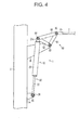
- FIG. 4 is an elevational view illustrating a mounting state of a tension balancer according to a second embodiment of the present invention.
- the present embodiment is a modification of the first embodiment, so that the same reference numerals are used for the same components, and descriptions thereof will be omitted.
- the balancer body 10 is turned upside down as compared to that of the first embodiment. More specifically, the mounting plate 24a of the outer housing 20 is connected to the pivotable connection portion 60, and the mounting portion 36 of the inner movable portion 30 is pivotably supported by the first support plate 3a.
- the rod insertion hole 26a of the second lid portion 26 is positioned at a lower portion of the outer housing 20, so that rainwater or the like is difficult to enter the outer housing 20 through the gap between the rod portion 32 and rod insertion hole 26a as compared to the tension balancer 1 of the first embodiment and, accordingly, the coil spring 40 is difficult to deteriorate.
- a load of the outer housing 20 is added to the force pulling the overhead line 2, so that it is possible to reduce the design value of elastic force of the coil spring 40. This can reduce a size of the coil spring 40 and reduce material quality thereof, resulting in a reduction of the entire size/cost of the tension balancer 1.
- FIG. 5 is an elevational view illustrating a mounting state of a tension balancer according to a third embodiment of the present invention.
- the present embodiment is a modification of the first embodiment, so that the same reference numerals are used for the same components, and descriptions thereof will be omitted.
- pivotable arms 68 are used as the pivotable connection portions 60.
- the pivotable arms 68 are each formed into a plate having substantially an L-shape.
- Each of the pivotable arms 68 has through holes at a corner portion and both end portions thereof.
- One stud bolt 82 is inserted through the through holes of the corner portions of the two pivotable arms 68 and the through hole of the second support plate 3b, whereby the two pivotable arms 68 are pivotably supported with respect to the support 3 about the stud bolt 82.
- One stud bolt 84 is inserted through the through holes of the mounting portions 36 of the two inner movable portions 30 and the through holes of one end portions of the two pivotable arms 68, whereby the inner movable portions 30 and pivotable arms are connected to each other.
- One stud bolt 86 is inserted through the through hole of the connector 2a of the overhead line 2 and the through holes of the other end portions of the two pivotable arms 68, whereby the overhead line 2 and the pivotable arms 68 are connected to each other.
- the present embodiment can provide the same effects as in the first embodiment.
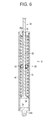
- FIG. 6 is a longitudinal cross-sectional view illustrating a balancer body of a tension balancer according to a fourth embodiment of the present invention.
- the present embodiment is a modification of the first embodiment, so that the same reference numerals are used for the same components, and descriptions thereof will be omitted.
- two coil springs are disposed in series in the outer housing 20.
- An intermediate spring receiver 42 is disposed between the two coil springs 40.
- the two coil springs 40 are wound reversely to each other.
- the number of the balancer bodies may be one or two or more.
- the number of the pivotable connection portions may be one or two or more.
- the two coil springs 40 are disposed in series in the outer housing 20 in the fourth embodiment, three or more coil spring may be used. Further, a plurality of the coil springs 40 may be disposed in parallel to each other in the outer housing 20.
- the present invention may be applied to other aerial lines, such as power lines.
Landscapes
- Engineering & Computer Science (AREA)
- Mechanical Engineering (AREA)
- Suspension Of Electric Lines Or Cables (AREA)
- Springs (AREA)
- Current-Collector Devices For Electrically Propelled Vehicles (AREA)
Abstract
Description
- Embodiments of the present invention relate to a tension balancer for maintaining a tension of an aerial line.
- An electric railway car receives power supply from an overhead line through a power collector such as a pantograph. When a tension of the overhead line changes due to expansion and contraction caused by a change in temperature, a contact state between the overhead line and the power collector is deteriorated to prevent stable power supply. In order to cope with this, a tension balancer for maintaining the tension of the overhead line is disposed between a support and the overhead line.
- As illustrated in
FIG. 7 , aconventional tension balancer 101 includes aspring case 120, alink rod 132, acoil spring 140, apivotable arm 168, and a frame 190 (see, e.g., Patent Document 1). - The
spring case 120 extends in a vertical direction in parallel to a support and is fixed to thesupport 103 by afixing band 103a. Thelink rod 132 extends from an inside of thespring case 120 to an outside thereof through arod insertion hole 126a formed in alid portion 126. A lower end of thelink rod 132 is rotatably connected to aspring receiving portion 134, and an upper end thereof is connected to thepivotable arm 168. - The
coil spring 140 is housed in thespring case 120. Thecoil spring 140 is sandwiched between thelid portion 126 and thespring receiving portion 134 in a compressed manner. - The
frame 190 is fixed to an upper end of thespring case 120. Theframe 190 is fixed to thesupport 103 by afixing band 103b. Thepivotable arm 168 is formed of substantially an L-shaped plate. A corner portion of thepivotable arm 168 is pivotably supported with respect to theframe 190. One end of thepivotable arm 168 is connected to the upper end of thelink rod 132, and the other end thereof is connected to theoverhead line 102. - The tension balancer 101 biases the
link rod 132 by elastic force of thecoil spring 140 in a direction in which thelink rod 132 retracts in thespring case 120 to impart an almost constant tension to theoverhead line 102 through thepivotable arm 168 pivotably supported. - Patent Document 1: Japanese Patent Application Laid-Open Publication No.
2009-166583 - In the conventional tension balancer 101, when the
pivotable arm 168 is pivoted about afulcrum 182 due to expansion and contraction of theoverhead line 102, thelink rod 132 moves in an extending/retracting direction with respect to thespring case 120 while being pivoted about aconnection point 138 to thespring receiving portion 134. However, since thespring case 120 is fixed to thesupport 103, an axial direction of thelink rod 132 and an axial direction of thespring case 120 do not always coincide with each other, thus preventing thelink rod 132 from pulling up thespring receiving portion 134 along the axis of thespring case 120. - Therefore, the
spring receiving portion 134 cannot be smoothly be slid in thespring case 120, which may adversely affect function of thetension balancer 101 or may cause noise. Further, force in a different direction from the axial direction is applied to thecoil spring 140, which may result in a reduction in durability of thecoil spring 140. - The present invention has been made to solve the above problem, and an object thereof is to provide a tension balancer excellent in function and quality.
- According to the present invention there is provided a tension balancer disposed between an aerial line and a support to maintain a tension of the aerial line, the tension balancer comprising: an outer housing formed in a tubular shape and pivotably supported at a lower end thereof by the support so as to be capable of being turned over; an inner movable portion inserted through the outer housing and protrudes from an upper end of the outer housing so as to be capable of extending and retracting in an axial direction of the outer housing; a coil spring housed in the outer housing and biasing the inner movable portion in a direction in which the inner movable portion retracts; and a pivotable connection portion having a fulcrum which is pivotably supported by the support, a movable portion connecting point to which an upper end of the inner movable portion is connected, and an aerial line connection portion to which the aerial line is connected and provided so as to be pivotable about the fulcrum.
- According to the present invention there is also provided a tension balancer disposed between an aerial line and a support to maintain a tension of the aerial line, the tension balancer comprising: an outer housing formed into a tubular shape; an inner movable portion inserted through the outer housing and protrudes from a lower end of the outer housing, pivotably supported at a lower end thereof by the support so as to be capable of being turned over, and provided so as to be capable of extending and retracting in an axial direction of the outer housing, a coil spring housed in the outer housing and biasing the inner movable portion in a direction in which the inner movable portion retracts; and a pivotable connection portion having a fulcrum which is pivotably supported by the support, a movable portion connecting point to which an upper end of the inner movable portion is connected, and an aerial line connection portion to which the aerial line is connected and provided so as to be pivotable about the fulcrum.
- According to the present invention there can be provided a tension balancer excellent in function and quality.
-
-
FIG. 1 is an elevational view illustrating a mounting state of a tension balancer according to a first embodiment of the present invention. -
FIG. 2 is a cross-sectional view taken along a II-II line ofFIG. 1 as viewed in the direction of the arrows. -
FIG. 3 is a longitudinal cross-sectional view illustrating a balancer body of the tension balancer according to the first embodiment of the present invention. -
FIG. 4 is an elevational view illustrating a mounting state of a tension balancer according to a second embodiment of the present invention. -
FIG. 5 is an elevational view illustrating a mounting state of a tension balancer according to a third embodiment of the present invention. -
FIG. 6 is a longitudinal cross-sectional view illustrating a balancer body of a tension balancer according to a fourth embodiment of the present invention. -
FIG. 7 is an elevational view illustrating a mounting state of a conventional tension balancer. - A tension balancer according to a first embodiment of the present invention will be described with reference to
FIGS. 1 to 3 .FIG. 1 is an elevational view illustrating a mounting state of a tension balancer, andFIG. 2 is a cross-sectional view taken along a II-II line ofFIG. 1 as viewed in the direction of the arrows.FIG. 3 is a longitudinal cross-sectional view illustrating a balancer body. - A tension balancer 1 according to the present embodiment is a tension balancer for a overhead line for electric railway cars. The
tension balancer 1 is disposed between a support body such as asupport 3 and anoverhead line 2 for electric railway cars to maintain a tension of the overhead line constant. - A configuration of the
tension balancer 1 according to the present embodiment will be described. - As illustrated in
FIGS. 1 and2 , thetension balancer 1 includes twobalancer bodies 10 disposed in parallel to each other and twopivotable connection portions 60. - As illustrated in
FIG. 3 , thebalancer bodies 10 each include anouter housing 20, an innermovable portion 30, and acoil spring 40. - The
outer housing 20 is pivotably supported at its lower end by thesupport 3 so as to be capable of being turned over. As illustrated inFIG. 3 , theouter housing 20 includes atubular portion 22 formed into a tubular shape, afirst lid portion 24, and asecond lid portion 26. - The
first lid portion 24 closes a lower end of thetubular portion 22. Thefirst lid portion 24 integrally has amounting plate 24a protruding from a lower surface thereof. Themounting plate 24a has a through hole therein. - The
support 3 has twofirst support plates 3a protruding in a direction in which theoverhead line 2 extends. The twofirst support plates 3a each have a through hole. Astud bolt 80 is inserted through the through holes of themounting plates 24a of the twoouter housings 20 and the through holes of the twofirst support plates 3a, and theouter housings 20 are each supported so as to be pivotable with respect to thesupport 3 about thestud bolt 80. - The
second lid portion 26 closes an upper end of thetubular portion 22 to serve as a spring seat of thecoil spring 40. Thesecond lid portion 26 has arod insertion hole 26a through which a rod portion 32 (to be described later) of the innermovable portion 30 is inserted. - The inner
movable portion 30 is inserted through theouter housing 20 and protrudes from an upper end of theouter housing 20 so as to be capable of extending and retracting in an axial direction of theouter housing 20. The innermovable portion 30 includes arod portion 32, aspring receiving portion 34, and amounting portion 36. - The
rod portion 32 is formed into a rod shape and extends along an axial center of theouter housing 20. Therod portion 32 extends from an inside of theouter housing 20 and protrudes from the upper end of theouter housing 20 through therod insertion hole 26a of thesecond lid portion 26. - The
spring receiving portion 34 is fixed to a lower end of therod portion 32 to serve as a spring seat of thecoil spring 40. Themounting portion 36 is provided at an upper end of therod portion 32. - The
coil spring 40 is housed inside theouter housing 20. Thecoil spring 40 helically extends along the axial direction of theouter housing 20. Thecoil spring 40 is sandwiched between thesecond lid portion 26 of theouter housing 20 and thespring receiving portion 34 of the innermovable portion 30 in a compressed manner. That is, thecoil spring 40 biases the innermovable portion 30 in a direction in which the innermovable portion 30 retracts in theouter housing 20. - As illustrated in
FIG. 1 , onepivotable connection portion 60 includes three long plates (a firstlong plate 62, a secondlong plate 64, and a third long plate 66). Each of the threelong plates Stud bolts long plate 62 and a first end portion of the secondlong plate 64, a second end portion of the secondlong plate 64 and a first end portion of the thirdlong plate 66, and a second end portion of the thirdlong plate 66 and a first end portion of the firstlong plate 62, respectively, whereby the threelong plates - The
support 3 has onesecond support plate 3b protruding in a direction in which theoverhead line 2 extends. Thesecond support plate 3b is formed at a position higher than the position of thefirst support plates 3a. Thesecond support plate 3b has a through hole. As illustrated inFIG. 2 , one stud bolt is inserted through the through holes of the firstlong plates 62 of the twopivotable connection portions 60, the through holes of the secondlong plates 64 thereof, and the through hole of thesecond support plate 3b, whereby the twopivotable connection portions 60 are supported so as to be pivotable with respect to thesupport 3 about thestud bolt 82. - One
stud bolt 84 is inserted through the through holes of the mountingportions 36 of the two innermovable portions 30, the through holes of the firstlong plates 62 of the twopivotable connection portions 60, and the through holes of the thirdlong plates 66 of the twopivotable connection portions 60, whereby the innermovable portions 30 and thepivotable connection portions 60 are connected to each other. - A
connector 2a is fixed to an end portion of theoverhead line 2. Theconnector 2a has a through hole. Onestud bolt 86 is inserted through the through hole of theconnector 2a of theoverhead line 2, the through holes of the secondlong plates 64 of the twopivotable connection portions 60, and the through holes of the thirdlong plates 66 of the twopivotable connection portions 60, whereby theoverhead line 2 and the innermovable portions 30 are connected to each other. - Operation and effect of the tension balancer according to the present embodiment will be described.
- In the
tension balancer 1, when theoverhead line 2 is expanded/contracted, thepivotable connection portion 60 is pivoted about the fulcrum (stud bolt) 82 and, accordingly, the innermovable portion 30 moves along the axis of theouter housing 20 to thereby maintain the tension of theoverhead line 2 almost constant. - As described above, in the
conventional tension balancer 101, when thepivotable arm 168 is pivoted about thefulcrum 182, thelink rod 132 moves in the extending/retracting direction with respect to thespring case 120 while being pivoted about theconnection point 138 to thespring receiving portion 134. However, since thespring case 120 is fixed to thesupport 103, the axial direction of thelink rod 132 and the axial direction of thespring case 120 do not always coincide with each other, thus preventing thelink rod 132 from pulling up thespring receiving portion 134 along the axis of thespring case 120. - Therefore, the
spring receiving portion 134 cannot be smoothly slid in thespring case 120, which may adversely affect function of thetension balancer 101 or may cause noise. Further, force in a different direction from the axial direction is applied to thecoil spring 140, which may result in a reduction in the life of thecoil spring 140. - On the other hand, in the
tension balancer 1 according to the present embodiment, the mountingplate 24a of theouter housing 20 is pivotably supported by thefirst support plate 3a, whereby thebalancer body 10 can be pivoted with respect to thesupport 3. Therefore, when thepivotable connection portion 60 is pivoted about the fulcrum (stud bolt) 82 due to the expansion or contraction of theoverhead line 2 to cause the connection point (stud bolt) 84 between thepivotable connection portion 60 and the innermovable portion 30, thebalancer body 10 is pivoted about thestud bolt 80. Thus, the innermovable portion 30 always moves along the axis of theouter housing 20. - Thus, according to the
tension balancer 1 of the present embodiment, thespring receiving portion 34 can be slid in theouter housing 20 more smoothly than thespring receiving portion 134 of theconventional tension balancer 101, making it easy for the function of the tension balancer to be exerted and making it difficult for noise due to the sliding movement of thespring receiving portion 34 to occur. Further, according to the present embodiment, force to thecoil spring 40 is always applied in the axial direction, thereby enhancing the durability of thecoil spring 40. - Further, in the
conventional tension balancer 101, thelink rod 132 is pivoted about theconnection point 138 to thespring receiving portion 134. Therefore, therod insertion hole 126a formed in thelid portion 126 of thespring case 120 needs to be large enough to allow pivot of thelink rod 132. As a result, making it easy for rainwater or the like to enter thespring case 120 through a gap, which easily leads to degradation of thecoil spring 140. - On the other hand, in the
tension balancer 1 according to the present embodiment, the axial direction of therod portion 32 and the axial direction of theouter housing 20 always coincide with each other, so that it is sufficient to make a diameter of therod insertion hole 26a of thesecond lid portion 26 slightly larger than the diameter of therod portion 32, thereby minimizing the gap between therod portion 32 and therod insertion hole 26a. Thus, according to thetension balancer 1 of the present embodiment, rainwater or the like is difficult to enter theouter housing 20 through the gap as compared to theconventional tension balancer 101 and, accordingly, thecoil spring 40 is difficult to deteriorate. - Further, in a configuration in which the
outer housing 20 is inclined relative to thesupport 3, a force (torque) for theouter housing 20 to turn over by its own weight is added to the force pulling theoverhead line 2, making it possible to reduce the design value of elastic force of thecoil spring 40. Thus, it is possible to reduce a size of thecoil spring 40 and reduce material quality thereof, resulting in a reduction of the entire size/cost of thetension balancer 1. - A tension balancer according to a second embodiment of the present invention will be described with reference to
FIG. 4. FIG. 4 is an elevational view illustrating a mounting state of a tension balancer according to a second embodiment of the present invention. The present embodiment is a modification of the first embodiment, so that the same reference numerals are used for the same components, and descriptions thereof will be omitted. - In the present embodiment, as illustrated in
FIG. 4 , thebalancer body 10 is turned upside down as compared to that of the first embodiment. More specifically, the mountingplate 24a of theouter housing 20 is connected to thepivotable connection portion 60, and the mountingportion 36 of the innermovable portion 30 is pivotably supported by thefirst support plate 3a. - According to the present embodiment, the
rod insertion hole 26a of thesecond lid portion 26 is positioned at a lower portion of theouter housing 20, so that rainwater or the like is difficult to enter theouter housing 20 through the gap between therod portion 32 androd insertion hole 26a as compared to thetension balancer 1 of the first embodiment and, accordingly, thecoil spring 40 is difficult to deteriorate. - Further, a load of the
outer housing 20 is added to the force pulling theoverhead line 2, so that it is possible to reduce the design value of elastic force of thecoil spring 40. This can reduce a size of thecoil spring 40 and reduce material quality thereof, resulting in a reduction of the entire size/cost of thetension balancer 1. - A tension balancer according to a third embodiment of the present invention will be described with reference to
FIG. 5. FIG. 5 is an elevational view illustrating a mounting state of a tension balancer according to a third embodiment of the present invention. The present embodiment is a modification of the first embodiment, so that the same reference numerals are used for the same components, and descriptions thereof will be omitted. - In the present embodiment, as illustrated in
FIG. 5 , twopivotable arms 68 are used as thepivotable connection portions 60. Thepivotable arms 68 are each formed into a plate having substantially an L-shape. Each of thepivotable arms 68 has through holes at a corner portion and both end portions thereof. - One
stud bolt 82 is inserted through the through holes of the corner portions of the twopivotable arms 68 and the through hole of thesecond support plate 3b, whereby the twopivotable arms 68 are pivotably supported with respect to thesupport 3 about thestud bolt 82. Onestud bolt 84 is inserted through the through holes of the mountingportions 36 of the two innermovable portions 30 and the through holes of one end portions of the twopivotable arms 68, whereby the innermovable portions 30 and pivotable arms are connected to each other. Onestud bolt 86 is inserted through the through hole of theconnector 2a of theoverhead line 2 and the through holes of the other end portions of the twopivotable arms 68, whereby theoverhead line 2 and thepivotable arms 68 are connected to each other. - The present embodiment can provide the same effects as in the first embodiment.
- A tension balancer according to a fourth embodiment of the present invention will be described with reference to
FIG. 6. FIG. 6 is a longitudinal cross-sectional view illustrating a balancer body of a tension balancer according to a fourth embodiment of the present invention. The present embodiment is a modification of the first embodiment, so that the same reference numerals are used for the same components, and descriptions thereof will be omitted. - In the present embodiment, as illustrated in
FIG. 6 , two coil springs are disposed in series in theouter housing 20. Anintermediate spring receiver 42 is disposed between the two coil springs 40. The twocoil springs 40 are wound reversely to each other. - According to the present embodiment, it is possible to impart a higher tension to the
overhead line 2 than in the first embodiment. - The embodiments described above are merely illustrative, and the present invention is not limited thereto. Further, the features of the embodiments may be combined. For example, the
pivotable arm 68 may be adopted in the second embodiment. - Although the two balancer bodies are used in the first embodiment, the number of the balancer bodies may be one or two or more. Further, although the two
pivotable connection portions 60 are used in the first embodiment, the number of the pivotable connection portions may be one or two or more. - Although the two
coil springs 40 are disposed in series in theouter housing 20 in the fourth embodiment, three or more coil spring may be used. Further, a plurality of the coil springs 40 may be disposed in parallel to each other in theouter housing 20. - Although the above descriptions have been made by taking the
overhead line 2 for electric railway cars as an example, the present invention may be applied to other aerial lines, such as power lines. -
- 1:
- Tension balancer
- 2:
- Overhead line
- 2a:
- Connector
- 3:
- Support
- 3a:
- First support plate
- 3b:
- Second support plate
- 10:
- Balancer body
- 20:
- Outer housing
- 22:
- Tubular portion
- 24:
- First lid portion
- 24a:
- Mounting plate
- 26:
- Second lid portion
- 26a:
- Rod insertion hole
- 30:
- Inner movable portion
- 32:
- Rod portion
- 34:
- Spring receiving portion
- 36:
- Mounting portion
- 40:
- Coil spring
- 42:
- Intermediate spring receiver
- 60:
- Pivotable connection portion
- 62:
- First long plate
- 64:
- Second long plate
- 66:
- Third long plate
- 68:
- Pivotable arm
- 80, 82, 84, 86:
- Stud bolt
Claims (4)
- A tension balancer disposed between an aerial line and a support to maintain a tension of the aerial line, the tension balancer comprising:an outer housing formed in a tubular shape and pivotably supported at a lower end thereof by the support so as to be capable of being turned over;an inner movable portion inserted through the outer housing and protrudes from an upper end of the outer housing so as to be capable of extending and retracting in an axial direction of the outer housing;a coil spring housed in the outer housing and biasing the inner movable portion in a direction in which the inner movable portion retracts; anda pivotable connection portion having a fulcrum which is pivotably supported by the support, a movable portion connecting point to which an upper end of the inner movable portion is connected, and an aerial line connection portion to which the aerial line is connected and provided so as to be pivotable about the fulcrum.
- The tension balancer according to claim 1, wherein
the outer housing has a tubular portion formed into a tubular shape and a lid portion for closing an upper end of the tubular portion,
the inner movable portion has a rod-like rod portion inserted through a rod insertion hole formed in the lid portion and a spring receiving portion provided at a lower end of the rod portion, and
the coil spring is disposed between the lid portion and the spring receiving portion in a compressed manner. - A tension balancer disposed between an aerial line and a support to maintain a tension of the aerial line, the tension balancer comprising:an outer housing formed into a tubular shape;an inner movable portion inserted through the outer housing and protrudes from a lower end of the outer housing, pivotably supported at a lower end thereof by the support so as to be capable of being turned over, and provided so as to be capable of extending and retracting in an axial direction of the outer housing,a coil spring housed in the outer housing and biasing the inner movable portion in a direction in which the inner movable portion retracts; anda pivotable connection portion having a fulcrum which is pivotably supported by the support, a movable portion connecting point to which an upper end of the inner movable portion is connected, and an aerial line connection portion to which the aerial line is connected and provided so as to be pivotable about the fulcrum.
- The tension balancer according to claim 3, wherein
the outer housing has a tubular portion formed into a tubular shape and a lid portion for closing a lower end of the tubular portion,
the inner movable portion has a rod-like rod portion inserted through a rod insertion hole formed in the lid portion and a spring receiving portion provided at an upper end of the rod portion, and
the coil spring is disposed between the lid portion and the spring receiving portion in a compressed manner.
Applications Claiming Priority (2)
| Application Number | Priority Date | Filing Date | Title |
|---|---|---|---|
| JP2010251507A JP5432877B2 (en) | 2010-11-10 | 2010-11-10 | Tension balancer |
| PCT/JP2011/004392 WO2012063384A1 (en) | 2010-11-10 | 2011-08-03 | Tension balancer |
Publications (2)
| Publication Number | Publication Date |
|---|---|
| EP2639100A1 true EP2639100A1 (en) | 2013-09-18 |
| EP2639100A4 EP2639100A4 (en) | 2014-08-06 |
Family
ID=46050558
Family Applications (1)
| Application Number | Title | Priority Date | Filing Date |
|---|---|---|---|
| EP20110839583 Withdrawn EP2639100A4 (en) | 2010-11-10 | 2011-08-03 | VOLTAGE COMPENSATOR |
Country Status (6)
| Country | Link |
|---|---|
| US (1) | US20130214117A1 (en) |
| EP (1) | EP2639100A4 (en) |
| JP (1) | JP5432877B2 (en) |
| KR (1) | KR101451750B1 (en) |
| CN (2) | CN202480904U (en) |
| WO (1) | WO2012063384A1 (en) |
Families Citing this family (7)
| Publication number | Priority date | Publication date | Assignee | Title |
|---|---|---|---|---|
| JP5432877B2 (en) * | 2010-11-10 | 2014-03-05 | 日本発條株式会社 | Tension balancer |
| JP6552214B2 (en) * | 2015-02-20 | 2019-07-31 | 三和テッキ株式会社 | Train line tension balancer |
| EP3061494A1 (en) * | 2015-02-27 | 2016-08-31 | Nihon Kohden Corporation | Link mechanism for arm portion |
| CN109888702B (en) * | 2018-12-26 | 2020-07-24 | 金华八达集团有限公司科技信息分公司 | A device for preventing sagging of a cross cable at an important intersection and a method of using the same |
| CN110789404A (en) * | 2019-10-30 | 2020-02-14 | 徐州中能电力科技有限公司 | Supporting mechanism of electrified railway contact net |
| CN113401010B (en) * | 2021-06-16 | 2022-11-08 | 中铁电气化勘测设计研究院有限公司 | Flexible sectional type movable contact net device |
| JP7607067B2 (en) * | 2023-03-22 | 2024-12-26 | 株式会社Nippo | Slope work equipment |
Family Cites Families (18)
| Publication number | Priority date | Publication date | Assignee | Title |
|---|---|---|---|---|
| GB1226440A (en) * | 1968-12-13 | 1971-03-31 | ||
| US4249585A (en) * | 1979-04-19 | 1981-02-10 | Mellott Hayes R | Log debarking apparatus |
| JPS5651641U (en) * | 1979-09-28 | 1981-05-07 | ||
| US4341335A (en) * | 1980-10-07 | 1982-07-27 | Sistig Corporation | Method and apparatus for controlling tension in a moving material |
| US4592697A (en) * | 1983-04-26 | 1986-06-03 | Kabushiki Kaisha Kobe Seiko Sho | Gravity balancing device for rocking arm |
| JPS604008B2 (en) * | 1984-03-19 | 1985-02-01 | 日本発条株式会社 | contact line support device |
| FR2597784B1 (en) * | 1986-04-25 | 1990-10-26 | Michelin & Cie | PROCESS AND APPARATUS FOR MANUFACTURING REINFORCEMENTS FOR TIRES |
| US5101735A (en) * | 1990-08-27 | 1992-04-07 | Williams Matti I | Constant tension apparatus and method with eccentric cam to regulate tension |
| EP1013499B1 (en) * | 1996-03-04 | 2003-02-12 | Central Japan Railway Company | An aerial line tensioning device |
| US6138964A (en) * | 1999-03-22 | 2000-10-31 | E & E Engineering, Inc. | Material handling unit with readily-removable bearing assembly |
| CN1124424C (en) * | 1999-09-28 | 2003-10-15 | 毛新悦 | Tension compensator with active constant-force disk spring for contact network of electrified railway |
| JP4628941B2 (en) * | 2005-12-08 | 2011-02-09 | 本田技研工業株式会社 | Electric motor control device |
| JP2008075818A (en) * | 2006-09-22 | 2008-04-03 | Nhk Spring Co Ltd | Tensile gas spring and tension gas spring device for railway overhead lines |
| JP4462634B2 (en) * | 2007-06-20 | 2010-05-12 | 生 西村 | Tension balancer for overhead wire |
| JP2009166583A (en) * | 2008-01-15 | 2009-07-30 | Sanwa Tekki Corp | Tension balancer of trolley wire |
| JP5036063B2 (en) * | 2008-06-10 | 2012-09-26 | 日本発條株式会社 | Tension balancer device for overhead wire and tension balancer waterproof cover for overhead wire |
| US9133762B2 (en) * | 2009-09-18 | 2015-09-15 | GM Global Technology Operations LLC | Drive belt tensioner for motor generator unit |
| JP5432877B2 (en) * | 2010-11-10 | 2014-03-05 | 日本発條株式会社 | Tension balancer |
-
2010
- 2010-11-10 JP JP2010251507A patent/JP5432877B2/en active Active
-
2011
- 2011-08-03 KR KR1020137008709A patent/KR101451750B1/en not_active Expired - Fee Related
- 2011-08-03 EP EP20110839583 patent/EP2639100A4/en not_active Withdrawn
- 2011-08-03 WO PCT/JP2011/004392 patent/WO2012063384A1/en not_active Ceased
- 2011-09-14 CN CN2011203509477U patent/CN202480904U/en not_active Expired - Lifetime
- 2011-09-14 CN CN201110281398.7A patent/CN102463907B/en active Active
-
2013
- 2013-04-01 US US13/854,485 patent/US20130214117A1/en not_active Abandoned
Also Published As
| Publication number | Publication date |
|---|---|
| WO2012063384A1 (en) | 2012-05-18 |
| CN202480904U (en) | 2012-10-10 |
| EP2639100A4 (en) | 2014-08-06 |
| US20130214117A1 (en) | 2013-08-22 |
| JP5432877B2 (en) | 2014-03-05 |
| KR101451750B1 (en) | 2014-10-16 |
| CN102463907B (en) | 2016-09-14 |
| KR20130051496A (en) | 2013-05-20 |
| CN102463907A (en) | 2012-05-23 |
| JP2012101667A (en) | 2012-05-31 |
Similar Documents
| Publication | Publication Date | Title |
|---|---|---|
| US20130214117A1 (en) | Tension balancer | |
| CA2472622A1 (en) | Compression spring rod | |
| CN102278419B (en) | Pipeline guiding device having resetting unit and manipulator with pipeline guiding device | |
| CN109987254B (en) | A parallel structure unmanned aerial vehicle force testing platform | |
| US20190036317A1 (en) | Grommet and grommet-equipped wire harness | |
| CN105637673A (en) | battery bay | |
| CN207607412U (en) | A kind of Anti-coresonance structure for automobile lamp | |
| CN103832484A (en) | Bouncing mechanism of car trunk | |
| CN209959705U (en) | Flexible embedded triangular arm elastic hinge part of automobile shell | |
| US20070120303A1 (en) | Vehicle suspension system | |
| CN104343776B (en) | The fixing device of outdoor AP | |
| CN202716751U (en) | Tension compensator | |
| CN108657038A (en) | Damper assembly, seat and vehicle | |
| CN201924717U (en) | Hinge for oven | |
| CN210763695U (en) | Elevator wire connecting plug-in with function is accomodate to electric wire | |
| JP4851968B2 (en) | pantograph | |
| JP2018167606A (en) | Device for decreasing tension variation of overhead wire | |
| CN204528495U (en) | A kind of elastics wing bearing | |
| US8463337B2 (en) | Sliding module with scratch prevention device | |
| CN202728000U (en) | Tension compensator | |
| CN213064477U (en) | Sliding rail support frame of high tensile resistance to compression of stability | |
| CN216691977U (en) | Piston assembly for air spring, air spring and vehicle | |
| CN202280286U (en) | Vehicle and door lock mechanism thereof | |
| CN216008182U (en) | Hinge structure for vehicle sliding door | |
| CN210165129U (en) | Locking structure for storage of pan-tilt |
Legal Events
| Date | Code | Title | Description |
|---|---|---|---|
| PUAI | Public reference made under article 153(3) epc to a published international application that has entered the european phase |
Free format text: ORIGINAL CODE: 0009012 |
|
| 17P | Request for examination filed |
Effective date: 20130403 |
|
| AK | Designated contracting states |
Kind code of ref document: A1 Designated state(s): AL AT BE BG CH CY CZ DE DK EE ES FI FR GB GR HR HU IE IS IT LI LT LU LV MC MK MT NL NO PL PT RO RS SE SI SK SM TR |
|
| DAX | Request for extension of the european patent (deleted) | ||
| A4 | Supplementary search report drawn up and despatched |
Effective date: 20140709 |
|
| RIC1 | Information provided on ipc code assigned before grant |
Ipc: B60M 1/26 20060101AFI20140703BHEP |
|
| GRAP | Despatch of communication of intention to grant a patent |
Free format text: ORIGINAL CODE: EPIDOSNIGR1 |
|
| INTG | Intention to grant announced |
Effective date: 20150407 |
|
| STAA | Information on the status of an ep patent application or granted ep patent |
Free format text: STATUS: THE APPLICATION IS DEEMED TO BE WITHDRAWN |
|
| 18D | Application deemed to be withdrawn |
Effective date: 20150818 |