EP2639039B1 - Screw shaft structure for double-shaft extruder - Google Patents
Screw shaft structure for double-shaft extruder Download PDFInfo
- Publication number
- EP2639039B1 EP2639039B1 EP12763032.5A EP12763032A EP2639039B1 EP 2639039 B1 EP2639039 B1 EP 2639039B1 EP 12763032 A EP12763032 A EP 12763032A EP 2639039 B1 EP2639039 B1 EP 2639039B1
- Authority
- EP
- European Patent Office
- Prior art keywords
- section
- screw shaft
- screw
- tapered
- outer diameter
- Prior art date
- Legal status (The legal status is an assumption and is not a legal conclusion. Google has not performed a legal analysis and makes no representation as to the accuracy of the status listed.)
- Active
Links
Images


Classifications
-
- B—PERFORMING OPERATIONS; TRANSPORTING
- B29—WORKING OF PLASTICS; WORKING OF SUBSTANCES IN A PLASTIC STATE IN GENERAL
- B29C—SHAPING OR JOINING OF PLASTICS; SHAPING OF MATERIAL IN A PLASTIC STATE, NOT OTHERWISE PROVIDED FOR; AFTER-TREATMENT OF THE SHAPED PRODUCTS, e.g. REPAIRING
- B29C48/00—Extrusion moulding, i.e. expressing the moulding material through a die or nozzle which imparts the desired form; Apparatus therefor
- B29C48/25—Component parts, details or accessories; Auxiliary operations
- B29C48/36—Means for plasticising or homogenising the moulding material or forcing it through the nozzle or die
- B29C48/395—Means for plasticising or homogenising the moulding material or forcing it through the nozzle or die using screws surrounded by a cooperating barrel, e.g. single screw extruders
- B29C48/40—Means for plasticising or homogenising the moulding material or forcing it through the nozzle or die using screws surrounded by a cooperating barrel, e.g. single screw extruders using two or more parallel screws or at least two parallel non-intermeshing screws, e.g. twin screw extruders
-
- B—PERFORMING OPERATIONS; TRANSPORTING
- B29—WORKING OF PLASTICS; WORKING OF SUBSTANCES IN A PLASTIC STATE IN GENERAL
- B29B—PREPARATION OR PRETREATMENT OF THE MATERIAL TO BE SHAPED; MAKING GRANULES OR PREFORMS; RECOVERY OF PLASTICS OR OTHER CONSTITUENTS OF WASTE MATERIAL CONTAINING PLASTICS
- B29B7/00—Mixing; Kneading
- B29B7/30—Mixing; Kneading continuous, with mechanical mixing or kneading devices
- B29B7/34—Mixing; Kneading continuous, with mechanical mixing or kneading devices with movable mixing or kneading devices
- B29B7/38—Mixing; Kneading continuous, with mechanical mixing or kneading devices with movable mixing or kneading devices rotary
- B29B7/46—Mixing; Kneading continuous, with mechanical mixing or kneading devices with movable mixing or kneading devices rotary with more than one shaft
-
- B—PERFORMING OPERATIONS; TRANSPORTING
- B29—WORKING OF PLASTICS; WORKING OF SUBSTANCES IN A PLASTIC STATE IN GENERAL
- B29B—PREPARATION OR PRETREATMENT OF THE MATERIAL TO BE SHAPED; MAKING GRANULES OR PREFORMS; RECOVERY OF PLASTICS OR OTHER CONSTITUENTS OF WASTE MATERIAL CONTAINING PLASTICS
- B29B7/00—Mixing; Kneading
- B29B7/30—Mixing; Kneading continuous, with mechanical mixing or kneading devices
- B29B7/34—Mixing; Kneading continuous, with mechanical mixing or kneading devices with movable mixing or kneading devices
- B29B7/38—Mixing; Kneading continuous, with mechanical mixing or kneading devices with movable mixing or kneading devices rotary
- B29B7/46—Mixing; Kneading continuous, with mechanical mixing or kneading devices with movable mixing or kneading devices rotary with more than one shaft
- B29B7/48—Mixing; Kneading continuous, with mechanical mixing or kneading devices with movable mixing or kneading devices rotary with more than one shaft with intermeshing devices, e.g. screws
- B29B7/488—Parts, e.g. casings, sealings; Accessories, e.g. flow controlling or throttling devices
- B29B7/489—Screws
-
- B—PERFORMING OPERATIONS; TRANSPORTING
- B29—WORKING OF PLASTICS; WORKING OF SUBSTANCES IN A PLASTIC STATE IN GENERAL
- B29B—PREPARATION OR PRETREATMENT OF THE MATERIAL TO BE SHAPED; MAKING GRANULES OR PREFORMS; RECOVERY OF PLASTICS OR OTHER CONSTITUENTS OF WASTE MATERIAL CONTAINING PLASTICS
- B29B7/00—Mixing; Kneading
- B29B7/30—Mixing; Kneading continuous, with mechanical mixing or kneading devices
- B29B7/58—Component parts, details or accessories; Auxiliary operations
-
- B—PERFORMING OPERATIONS; TRANSPORTING
- B29—WORKING OF PLASTICS; WORKING OF SUBSTANCES IN A PLASTIC STATE IN GENERAL
- B29C—SHAPING OR JOINING OF PLASTICS; SHAPING OF MATERIAL IN A PLASTIC STATE, NOT OTHERWISE PROVIDED FOR; AFTER-TREATMENT OF THE SHAPED PRODUCTS, e.g. REPAIRING
- B29C48/00—Extrusion moulding, i.e. expressing the moulding material through a die or nozzle which imparts the desired form; Apparatus therefor
- B29C48/03—Extrusion moulding, i.e. expressing the moulding material through a die or nozzle which imparts the desired form; Apparatus therefor characterised by the shape of the extruded material at extrusion
- B29C48/07—Flat, e.g. panels
- B29C48/08—Flat, e.g. panels flexible, e.g. films
-
- B—PERFORMING OPERATIONS; TRANSPORTING
- B29—WORKING OF PLASTICS; WORKING OF SUBSTANCES IN A PLASTIC STATE IN GENERAL
- B29C—SHAPING OR JOINING OF PLASTICS; SHAPING OF MATERIAL IN A PLASTIC STATE, NOT OTHERWISE PROVIDED FOR; AFTER-TREATMENT OF THE SHAPED PRODUCTS, e.g. REPAIRING
- B29C48/00—Extrusion moulding, i.e. expressing the moulding material through a die or nozzle which imparts the desired form; Apparatus therefor
- B29C48/25—Component parts, details or accessories; Auxiliary operations
-
- B—PERFORMING OPERATIONS; TRANSPORTING
- B29—WORKING OF PLASTICS; WORKING OF SUBSTANCES IN A PLASTIC STATE IN GENERAL
- B29C—SHAPING OR JOINING OF PLASTICS; SHAPING OF MATERIAL IN A PLASTIC STATE, NOT OTHERWISE PROVIDED FOR; AFTER-TREATMENT OF THE SHAPED PRODUCTS, e.g. REPAIRING
- B29C48/00—Extrusion moulding, i.e. expressing the moulding material through a die or nozzle which imparts the desired form; Apparatus therefor
- B29C48/25—Component parts, details or accessories; Auxiliary operations
- B29C48/252—Drive or actuation means; Transmission means; Screw supporting means
- B29C48/2526—Direct drives or gear boxes
-
- B—PERFORMING OPERATIONS; TRANSPORTING
- B29—WORKING OF PLASTICS; WORKING OF SUBSTANCES IN A PLASTIC STATE IN GENERAL
- B29C—SHAPING OR JOINING OF PLASTICS; SHAPING OF MATERIAL IN A PLASTIC STATE, NOT OTHERWISE PROVIDED FOR; AFTER-TREATMENT OF THE SHAPED PRODUCTS, e.g. REPAIRING
- B29C48/00—Extrusion moulding, i.e. expressing the moulding material through a die or nozzle which imparts the desired form; Apparatus therefor
- B29C48/25—Component parts, details or accessories; Auxiliary operations
- B29C48/256—Exchangeable extruder parts
- B29C48/2561—Mounting or handling of the screw
-
- B—PERFORMING OPERATIONS; TRANSPORTING
- B29—WORKING OF PLASTICS; WORKING OF SUBSTANCES IN A PLASTIC STATE IN GENERAL
- B29C—SHAPING OR JOINING OF PLASTICS; SHAPING OF MATERIAL IN A PLASTIC STATE, NOT OTHERWISE PROVIDED FOR; AFTER-TREATMENT OF THE SHAPED PRODUCTS, e.g. REPAIRING
- B29C48/00—Extrusion moulding, i.e. expressing the moulding material through a die or nozzle which imparts the desired form; Apparatus therefor
- B29C48/25—Component parts, details or accessories; Auxiliary operations
- B29C48/256—Exchangeable extruder parts
- B29C48/2564—Screw parts
-
- B—PERFORMING OPERATIONS; TRANSPORTING
- B29—WORKING OF PLASTICS; WORKING OF SUBSTANCES IN A PLASTIC STATE IN GENERAL
- B29C—SHAPING OR JOINING OF PLASTICS; SHAPING OF MATERIAL IN A PLASTIC STATE, NOT OTHERWISE PROVIDED FOR; AFTER-TREATMENT OF THE SHAPED PRODUCTS, e.g. REPAIRING
- B29C48/00—Extrusion moulding, i.e. expressing the moulding material through a die or nozzle which imparts the desired form; Apparatus therefor
- B29C48/25—Component parts, details or accessories; Auxiliary operations
- B29C48/256—Exchangeable extruder parts
- B29C48/2568—Inserts
- B29C48/25682—Inserts for screws
-
- B—PERFORMING OPERATIONS; TRANSPORTING
- B29—WORKING OF PLASTICS; WORKING OF SUBSTANCES IN A PLASTIC STATE IN GENERAL
- B29C—SHAPING OR JOINING OF PLASTICS; SHAPING OF MATERIAL IN A PLASTIC STATE, NOT OTHERWISE PROVIDED FOR; AFTER-TREATMENT OF THE SHAPED PRODUCTS, e.g. REPAIRING
- B29C48/00—Extrusion moulding, i.e. expressing the moulding material through a die or nozzle which imparts the desired form; Apparatus therefor
- B29C48/25—Component parts, details or accessories; Auxiliary operations
- B29C48/36—Means for plasticising or homogenising the moulding material or forcing it through the nozzle or die
- B29C48/50—Details of extruders
- B29C48/505—Screws
- B29C48/507—Screws characterised by the material or their manufacturing process
-
- B—PERFORMING OPERATIONS; TRANSPORTING
- B29—WORKING OF PLASTICS; WORKING OF SUBSTANCES IN A PLASTIC STATE IN GENERAL
- B29C—SHAPING OR JOINING OF PLASTICS; SHAPING OF MATERIAL IN A PLASTIC STATE, NOT OTHERWISE PROVIDED FOR; AFTER-TREATMENT OF THE SHAPED PRODUCTS, e.g. REPAIRING
- B29C48/00—Extrusion moulding, i.e. expressing the moulding material through a die or nozzle which imparts the desired form; Apparatus therefor
- B29C48/25—Component parts, details or accessories; Auxiliary operations
- B29C48/36—Means for plasticising or homogenising the moulding material or forcing it through the nozzle or die
- B29C48/50—Details of extruders
- B29C48/505—Screws
- B29C48/63—Screws having sections without mixing elements or threads, i.e. having cylinder shaped sections
-
- F—MECHANICAL ENGINEERING; LIGHTING; HEATING; WEAPONS; BLASTING
- F01—MACHINES OR ENGINES IN GENERAL; ENGINE PLANTS IN GENERAL; STEAM ENGINES
- F01C—ROTARY-PISTON OR OSCILLATING-PISTON MACHINES OR ENGINES
- F01C1/00—Rotary-piston machines or engines
- F01C1/08—Rotary-piston machines or engines of intermeshing engagement type, i.e. with engagement of co- operating members similar to that of toothed gearing
- F01C1/082—Details specially related to intermeshing engagement type machines or engines
-
- F—MECHANICAL ENGINEERING; LIGHTING; HEATING; WEAPONS; BLASTING
- F01—MACHINES OR ENGINES IN GENERAL; ENGINE PLANTS IN GENERAL; STEAM ENGINES
- F01C—ROTARY-PISTON OR OSCILLATING-PISTON MACHINES OR ENGINES
- F01C1/00—Rotary-piston machines or engines
- F01C1/08—Rotary-piston machines or engines of intermeshing engagement type, i.e. with engagement of co- operating members similar to that of toothed gearing
- F01C1/12—Rotary-piston machines or engines of intermeshing engagement type, i.e. with engagement of co- operating members similar to that of toothed gearing of other than internal-axis type
- F01C1/14—Rotary-piston machines or engines of intermeshing engagement type, i.e. with engagement of co- operating members similar to that of toothed gearing of other than internal-axis type with toothed rotary pistons
- F01C1/20—Rotary-piston machines or engines of intermeshing engagement type, i.e. with engagement of co- operating members similar to that of toothed gearing of other than internal-axis type with toothed rotary pistons with dissimilar tooth forms
-
- F—MECHANICAL ENGINEERING; LIGHTING; HEATING; WEAPONS; BLASTING
- F04—POSITIVE - DISPLACEMENT MACHINES FOR LIQUIDS; PUMPS FOR LIQUIDS OR ELASTIC FLUIDS
- F04C—ROTARY-PISTON, OR OSCILLATING-PISTON, POSITIVE-DISPLACEMENT MACHINES FOR LIQUIDS; ROTARY-PISTON, OR OSCILLATING-PISTON, POSITIVE-DISPLACEMENT PUMPS
- F04C2/00—Rotary-piston machines or pumps
- F04C2/30—Rotary-piston machines or pumps having the characteristics covered by two or more groups F04C2/02, F04C2/08, F04C2/22, F04C2/24 or having the characteristics covered by one of these groups together with some other type of movement between co-operating members
- F04C2/36—Rotary-piston machines or pumps having the characteristics covered by two or more groups F04C2/02, F04C2/08, F04C2/22, F04C2/24 or having the characteristics covered by one of these groups together with some other type of movement between co-operating members having both the movements defined in groups F04C2/22 and F04C2/24
Definitions
- the present invention relates to a screw shaft structure for a twin screw extruder, and more particularly, to a novel improvement for reducing a weight of a raw material, which is used for manufacturing a screw shaft, by combining a tapered section and a tapered ring as a structure of a flange section.
- Patent Literature 1 As a conventionally used screw shaft structure for a twin screw extruder of this type, the structure disclosed in Patent Literature 1 may be taken as an example.
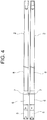
- Patent Literature 1 is configured as illustrated in FIGS. 4 and 5 .
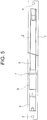
- reference symbol 1 represents a screw shaft raw material to be used for manufacturing a screw shaft 2 through a cutting process.
- the screw shaft raw material 1 has a pair of suspension holes 3 and 4 provided at both ends thereof, and the screw shaft raw material 1 can be transported through the suspension holes 3 and 4.
- connection section 5 to be connected to a gear reducer of a drive motor (not shown), a ground section 6 formed integrally with the connection section 5, a flange section 7 formed on a downstream side of the ground section 6, and a screw piece inserting section 8 connected to the flange section 7 and to be used for insertion of a plurality of screw segments are formed through the cutting process.
- two screw shafts 2 are provided in parallel inside a cylinder (not shown) and formed as the twin screw extruder described above.
- Literature 2 describes a device including two screws freely rotatably arranged in connected divided cylinders.
- the slide keys are linearly moved in the orthogonal direction to the divided cylinder shaft direction along guide recessed parts and accompanied with this, projected line parts inclining to the axial line are slid along inclined key channels formed on divided tapered rings and the divided tapered rings are linearly moved reversely in the axial direction of the divided cylinder.
- a gap (a flow path) between tapered parts of the divided tapered ring and the tapered face of a collar-shaped part is changed in a range between the min. gap and the max. gap.
- Literature 3 relates to a plant comprising successive regions on along which a mass is conveyed, namely: a first region with a first process chamber in which a mixing of the material takes place and is entered in the mass mechanical and / or thermal energy; a second region with a second process chamber which takes place in a pressure build-up in the mass; and a third region for accommodating the ejectedmass from the second region.
- Aformingunit (5) is arranged between the second region and the third region comprises, with which the pressurized mass prior to their emission in the third region can be deformed to a particular shape.
- Literature 4 describes a screw shaft joint device of an extruder connecting the output shaft of a gear box transmitting power from a drive source and a screw shaft, an output shaft having a first power transmission means provided to the leading end part thereof, the screw shaft provided with a taper stepped part having a diameter less than that of a shaft having a secondpower transmission means provided to the end part thereof on the side of the output shaft and having a second transmission means provided thereto on the side opposite to the output shaft of the secondpower transmission means; a shaft joint having the output shaft and the screw shaft fitted in both end parts thereof and having a male screw provided to the end part thereof on the side of the screw shaft and at least two slots having a long diameter in the axial direction thereof provided thereto in the circumferential direction thereof at the position opposed to the taper stepped part of the screw shaft, a stopper means preventing the slip-off of the screw shaft from the shaft joint in contact with the taper stepped part of the screw shaft and a nut threaded with the male screw of the shaft joint by
- the conventional screw shaft structure for a twin screw extruder is formed as described above, and hence the following problems are inherent therein.
- the conventional screw shaft 2 includes the flange section 7 that is integrally formed between the ground section 6 and the screw piece inserting section 8, and hence an outer diameter of the flange section 7 is the largest outer diameter of the screw shaft 2.
- a part having the smallest outer diameter is the screw piece inserting section 8 to be used for insertion of a plurality of screw segments.
- the screw piece inserting section 8 occupies the largest axial length.
- the screw shaft 2 is manufactured through the cutting process from the screw shaft raw material 1 that is formed of an elongated columnar body, and hence an outer diameter of the screw shaft raw material 1 needs to be set equal to or larger than the outer diameter of the flange section 7.
- an outer diameter of the screw shaft raw material 1 needs to be set equal to or larger than the outer diameter of the flange section 7.
- a screw shaft structure for a twin screw extruder comprising at least a connection section to be connected to a gear reducer, a ground section extending distally from the connection section, and a screw piece inserting section extending distally from the ground section
- the screw shaft structure for a twin screw extruder further comprising a tapered section provided between the ground section and the screw piece inserting section
- the screw shaft structure being characterized in that it further includes a tapered ring fitted onto the tapered section, the tapered ring serving as a flange section, and screw elements to be inserted onto the screw piece inserting section which are positioned and fixed by said tapered ring.
- an outer diameter of the tapered section is set equal to or smaller than a ground section outer diameter of the ground section.
- the screw shaft structure for a twin screw extruder according to the present invention is configured as described above, and hence the following effects can be obtained.
- the tapered section is providedbetween the ground section and the screw piece inserting section, and the tapered ring is fitted onto the tapered section to serve as a flange section. Accordingly, it is only the tapered section that is manufactured from the screw shaft blank at a position between the ground section and the screw piece inserting section.
- the outer diameter is reduced as compared to the conventional flange section so that the outer diameter of the screw shaft raw material can be reduced and the weight and shape of the screw shaft raw material can also be reduced. Further, the cost for the raw material and the period of time required for the processing are reduced so that the cost for the processing can be reduced.
- the effect of reducing the weight of the blank is 30%, and the effect of reducing the period of time required for the mechanical processing is 20%.
- the cost reduction including the cost for the rawmaterial and processing is about 40%.
- the outer diameter of the tapered section is set equal to or smaller than the ground section outer diameter of the ground section. Accordingly, the largest outer diameter is only the outer diameter of the ground section over the entire length of the screw shaft manufactured from the screw shaft blank. Thus, as compared to the conventional screw shaft, the outer diameter of the screw shaft blank can be reduced, and the cost for the material of the screw shaft raw material can be reduced.
- the present invention has an object to provide a screw shaft structure for a twin screw extruder, which is capable of reducing a weight of a raw material to be used for manufacturing a screw shaft by combining a tapered section and a tapered ring as a structure of the flange section.
- reference symbol 1 represents a screw shaft raw material to be used for manufacturing a screw shaft 2 through a cutting process.
- the screw shaft raw material 1 has a pair of suspension holes 3 and 4 provided at both ends thereof, and the screw shaft raw material 1 can be transported through the suspension holes 3 and 4.
- connection section 5 to be connected to a gear reducer of a drive motor (not shown), a ground section 6 formed integrally with the connection section 5, and a tapered section 20 formed on a downstream side of the ground section 6 at a position between the ground section 6 and a screw piece inserting section 8 are formed through the cutting process.
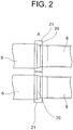
- the tapered section 20 is illustrated in the region A of FIG. 1 , and is illustrated in FIG. 2 in an enlarged manner.
- An outer diameter of the tapered section 20 thus formed is set equal to or smaller than a ground section outer diameter 6a of the ground section 6.
- the outer diameter of the tapered section 20 is set equal to or smaller than the ground section outer diameter 6a, and hence a part of the screw shaft 2 having the largest outer diameter is the part having the ground section outer diameter 6a.
- an outer diameter of the screw shaft raw material 1 can be reduced more greatly as compared to the outer diameter of the conventional screw shaft raw material 1, and the weight thereof can also be reduced greatly.
- a tapered ring 21 having an inner surface shape conforming to an outer surface shape of the tapered section 20 is fitted onto an outer periphery of the tapered section 20, and screw segments (not shown) to be inserted onto the screw piece inserting section 8 are positioned and fixed by the tapered ring 21 so that an action corresponding to that of the conventional flange section 7 can be obtained.
- the tapered section 20 serves as a part on which the tapered ring 21 is fitted, and hence stress concentration is avoided and damage and the like can be prevented.
- the largest outer diameter of the screw shaft 2 is the ground section outer diameter 6a of the ground section 6, and hence, by setting the outer diameter of the screw shaft raw material 1 to be equal to the ground section outer diameter 6a, the screw shaft raw material 1 can be reduced greatly.
- the screw shaft structure for a twin screw extruder according to the present invention is formed of the tapered section and the tapered ring which serve as the conventional flange section. Accordingly, the outer diameter of the screw shaft raw material can be reduced greatly, and the cost required therefor can be reduced greatly.
Landscapes
- Engineering & Computer Science (AREA)
- Mechanical Engineering (AREA)
- General Engineering & Computer Science (AREA)
- Manufacturing & Machinery (AREA)
- Extrusion Moulding Of Plastics Or The Like (AREA)
- Processing And Handling Of Plastics And Other Materials For Molding In General (AREA)
Description
- The present invention relates to a screw shaft structure for a twin screw extruder, and more particularly, to a novel improvement for reducing a weight of a raw material, which is used for manufacturing a screw shaft, by combining a tapered section and a tapered ring as a structure of a flange section.
- As a conventionally used screw shaft structure for a twin screw extruder of this type, the structure disclosed in
Patent Literature 1 may be taken as an example. - That is, the above-mentioned screw shaft structure of
Patent Literature 1 is configured as illustrated inFIGS. 4 and5 . - Specifically, in
FIG. 5 ,reference symbol 1 represents a screw shaft raw material to be used for manufacturing ascrew shaft 2 through a cutting process. The screw shaftraw material 1 has a pair ofsuspension holes raw material 1 can be transported through thesuspension holes - From the screw shaft
raw material 1, aconnection section 5 to be connected to a gear reducer of a drive motor (not shown), aground section 6 formed integrally with theconnection section 5, aflange section 7 formed on a downstream side of theground section 6, and a screwpiece inserting section 8 connected to theflange section 7 and to be used for insertion of a plurality of screw segments are formed through the cutting process. - Note that, as illustrated in
FIG. 4 , twoscrew shafts 2 are provided in parallel inside a cylinder (not shown) and formed as the twin screw extruder described above. - Besides,
Literature 2 describes a device including two screws freely rotatably arranged in connected divided cylinders. When screw shafts screwed in screw holes of slide keys are rotated normally and reversely, the slide keys are linearly moved in the orthogonal direction to the divided cylinder shaft direction along guide recessed parts and accompanied with this, projected line parts inclining to the axial line are slid along inclined key channels formed on divided tapered rings and the divided tapered rings are linearly moved reversely in the axial direction of the divided cylinder. As the result, a gap (a flow path) between tapered parts of the divided tapered ring and the tapered face of a collar-shaped part is changed in a range between the min. gap and the max. gap. -
Literature 3 relates to a plant comprising successive regions on along which a mass is conveyed, namely: a first region with a first process chamber in which a mixing of the material takes place and is entered in the mass mechanical and / or thermal energy; a second region with a second process chamber which takes place in a pressure build-up in the mass; and a third region for accommodating the ejectedmass from the second region. Aformingunit (5) is arranged between the second region and the third region comprises, with which the pressurized mass prior to their emission in the third region can be deformed to a particular shape. - Besides,
Literature 4 describes a screw shaft joint device of an extruder connecting the output shaft of a gear box transmitting power from a drive source and a screw shaft, an output shaft having a first power transmission means provided to the leading end part thereof, the screw shaft provided with a taper stepped part having a diameter less than that of a shaft having a secondpower transmission means provided to the end part thereof on the side of the output shaft and having a second transmission means provided thereto on the side opposite to the output shaft of the secondpower transmission means; a shaft joint having the output shaft and the screw shaft fitted in both end parts thereof and having a male screw provided to the end part thereof on the side of the screw shaft and at least two slots having a long diameter in the axial direction thereof provided thereto in the circumferential direction thereof at the position opposed to the taper stepped part of the screw shaft, a stopper means preventing the slip-off of the screw shaft from the shaft joint in contact with the taper stepped part of the screw shaft and a nut threaded with the male screw of the shaft joint by its inner diameter part and pressing the stopper means to the taper stepped part of the screw shaft are provided. -
- [PTL 1]
JP 2005-22091 A - [PLT 2]
JP 2877791 B1 - [PLT 3]
DE 10 2005 010315 - [PLT 4]
JP 2000-301590 - The conventional screw shaft structure for a twin screw extruder is formed as described above, and hence the following problems are inherent therein.
- Specifically, the
conventional screw shaft 2 includes theflange section 7 that is integrally formed between theground section 6 and the screwpiece inserting section 8, and hence an outer diameter of theflange section 7 is the largest outer diameter of thescrew shaft 2. - In contrast, a part having the smallest outer diameter is the screw
piece inserting section 8 to be used for insertion of a plurality of screw segments. The screwpiece inserting section 8 occupies the largest axial length. - Therefore, as illustrated in
FIG. 5 , thescrew shaft 2 is manufactured through the cutting process from the screw shaftraw material 1 that is formed of an elongated columnar body, and hence an outer diameter of the screw shaftraw material 1 needs to be set equal to or larger than the outer diameter of theflange section 7. When thescrew shaft 2 is manufactured from the screw shaftraw material 1 in this state, a large amount of unnecessary portions are generated particularly from the part corresponding to the screwpiece inserting section 8 that is smaller in diameter than theflange section 7. Accordingly, such structure is wasteful in terms of cost and raw material, resulting in an increase in weight of the blank relative to a weight of thescrew shaft 2 as a final product. - According to the present invention, there is provided a screw shaft structure for a twin screw extruder according to
claim 1, comprising at least a connection section to be connected to a gear reducer, a ground section extending distally from the connection section, and a screw piece inserting section extending distally from the ground section, the screw shaft structure for a twin screw extruder further comprising a tapered section provided between the ground section and the screw piece inserting section, the screw shaft structure being characterized in that it further includes a tapered ring fitted onto the tapered section, the tapered ring serving as a flange section, and screw elements to be inserted onto the screw piece inserting section which are positioned and fixed by said tapered ring. - Further, an outer diameter of the tapered section is set equal to or smaller than a ground section outer diameter of the ground section.
- The screw shaft structure for a twin screw extruder according to the present invention is configured as described above, and hence the following effects can be obtained.
- Specifically, in the screw shaft structure for a twin screw extruder, which includes at least the connection section to be connected to a gear reducer, the ground section, and the screw piece inserting section, the tapered section is providedbetween the ground section and the screw piece inserting section, and the tapered ring is fitted onto the tapered section to serve as a flange section. Accordingly, it is only the tapered section that is manufactured from the screw shaft blank at a position between the ground section and the screw piece inserting section. Thus, the outer diameter is reduced as compared to the conventional flange section so that the outer diameter of the screw shaft raw material can be reduced and the weight and shape of the screw shaft raw material can also be reduced. Further, the cost for the raw material and the period of time required for the processing are reduced so that the cost for the processing can be reduced.
- Further, as compared actually to the conventional structure, the effect of reducing the weight of the blank is 30%, and the effect of reducing the period of time required for the mechanical processing is 20%.
- Thus, the cost reduction including the cost for the rawmaterial and processing is about 40%.
- Further, the outer diameter of the tapered section is set equal to or smaller than the ground section outer diameter of the ground section. Accordingly, the largest outer diameter is only the outer diameter of the ground section over the entire length of the screw shaft manufactured from the screw shaft blank. Thus, as compared to the conventional screw shaft, the outer diameter of the screw shaft blank can be reduced, and the cost for the material of the screw shaft raw material can be reduced.
-
- [
FIG. 1 ] A sectional plan view illustrating a screw shaft structure for a twin screw extruder according to the present invention. - [
FIG. 2 ] An enlarged view of the region A ofFIG. 1 . - [
FIG. 3 ] An explanatory view illustrating a screw shaft raw material in a state in which a single screw shaft ofFIG. 1 is subjected to a cutting process. - [
FIG. 4 ] A sectional plan view illustrating a conventional screw shaft structure for a twin screw extruder. - [
FIG. 5 ] An explanatory view illustrating a screw shaft raw material in a state in which a screw shaft ofFIG. 4 is subjected to the cutting process. - The present invention has an object to provide a screw shaft structure for a twin screw extruder, which is capable of reducing a weight of a raw material to be used for manufacturing a screw shaft by combining a tapered section and a tapered ring as a structure of the flange section.
- In the following, a screw shaft structure for a twin screw extruder according to an exemplary embodiment of the present invention is described with reference to the drawings.
- Note that, the same components as those of the conventional example or components corresponding thereto are represented by the same reference symbols.
- In
FIG. 3 ,reference symbol 1 represents a screw shaft raw material to be used for manufacturing ascrew shaft 2 through a cutting process. The screw shaftraw material 1 has a pair ofsuspension holes raw material 1 can be transported through thesuspension holes - From the screw shaft raw material, a
connection section 5 to be connected to a gear reducer of a drive motor (not shown), aground section 6 formed integrally with theconnection section 5, and atapered section 20 formed on a downstream side of theground section 6 at a position between theground section 6 and a screwpiece inserting section 8 are formed through the cutting process. Note that, thetapered section 20 is illustrated in the region A ofFIG. 1 , and is illustrated inFIG. 2 in an enlarged manner. - An outer diameter of the
tapered section 20 thus formed is set equal to or smaller than a ground sectionouter diameter 6a of theground section 6. - As described above, the outer diameter of the
tapered section 20 is set equal to or smaller than the ground sectionouter diameter 6a, and hence a part of thescrew shaft 2 having the largest outer diameter is the part having the ground sectionouter diameter 6a. As a result, an outer diameter of the screw shaftraw material 1 can be reduced more greatly as compared to the outer diameter of the conventional screw shaftraw material 1, and the weight thereof can also be reduced greatly. - Further, as illustrated in
FIGS. 1 and2 , atapered ring 21 having an inner surface shape conforming to an outer surface shape of thetapered section 20 is fitted onto an outer periphery of thetapered section 20, and screw segments (not shown) to be inserted onto the screwpiece inserting section 8 are positioned and fixed by thetapered ring 21 so that an action corresponding to that of theconventional flange section 7 can be obtained. Note that, thetapered section 20 serves as a part on which thetapered ring 21 is fitted, and hence stress concentration is avoided and damage and the like can be prevented. - Thus, the largest outer diameter of the
screw shaft 2 is the ground sectionouter diameter 6a of theground section 6, and hence, by setting the outer diameter of the screw shaftraw material 1 to be equal to the ground sectionouter diameter 6a, the screw shaftraw material 1 can be reduced greatly. - The screw shaft structure for a twin screw extruder according to the present invention is formed of the tapered section and the tapered ring which serve as the conventional flange section. Accordingly, the outer diameter of the screw shaft raw material can be reduced greatly, and the cost required therefor can be reduced greatly.
Claims (2)
- A screw shaft structure for a twin screw extruder, comprising at least:a connection section (5) to be connected to a gear reducer;a ground section (6) extending distally from the connection section (5); anda screw piece inserting section (8) extending distally from the ground section (6),the screw shaft structure for a twin screw extruder further comprising:a tapered section (20) provided between the ground section (6) and the screw piece inserting section (8);the screw shaft structure being characterized in that it further includes a tapered ring (21) fitted onto the tapered section (20), the tapered ring (21) serving as a flange section, and screw elements to be inserted onto the screw piece inserting section (8) which are positioned and fixed by said tapered ring (21).
- A screw shaft structure for a twin screw extruder according to claim 1, wherein an outer diameter of the tapered section (20) is set equal to or smaller than a ground section outer diameter (6a) of the ground section (6).
Applications Claiming Priority (2)
| Application Number | Priority Date | Filing Date | Title |
|---|---|---|---|
| JP2011077325A JP5463318B2 (en) | 2011-03-31 | 2011-03-31 | Screw shaft structure for twin screw extruder |
| PCT/JP2012/058530 WO2012133742A1 (en) | 2011-03-31 | 2012-03-30 | Screw shaft structure for double-shaft extruder |
Publications (3)
| Publication Number | Publication Date |
|---|---|
| EP2639039A1 EP2639039A1 (en) | 2013-09-18 |
| EP2639039A4 EP2639039A4 (en) | 2014-11-19 |
| EP2639039B1 true EP2639039B1 (en) | 2017-01-11 |
Family
ID=46931440
Family Applications (1)
| Application Number | Title | Priority Date | Filing Date |
|---|---|---|---|
| EP12763032.5A Active EP2639039B1 (en) | 2011-03-31 | 2012-03-30 | Screw shaft structure for double-shaft extruder |
Country Status (6)
| Country | Link |
|---|---|
| US (1) | US9057264B2 (en) |
| EP (1) | EP2639039B1 (en) |
| JP (1) | JP5463318B2 (en) |
| KR (1) | KR102014244B1 (en) |
| CN (1) | CN103282183B (en) |
| WO (1) | WO2012133742A1 (en) |
Families Citing this family (2)
| Publication number | Priority date | Publication date | Assignee | Title |
|---|---|---|---|---|
| DE102017111284B4 (en) | 2017-05-23 | 2018-12-06 | Veka Ag | Extruder screw shaft pair for a twin-screw extruder |
| JP7507081B2 (en) * | 2020-12-21 | 2024-06-27 | 芝浦機械株式会社 | Screw Machine |
Citations (2)
| Publication number | Priority date | Publication date | Assignee | Title |
|---|---|---|---|---|
| JP2000301590A (en) * | 1999-04-26 | 2000-10-31 | Toshiba Mach Co Ltd | Screw shaft joint device for extruder |
| JP2011189550A (en) * | 2010-03-12 | 2011-09-29 | Toshiba Mach Co Ltd | Split-type collar for fixing screw shaft of extruder and the extruder |
Family Cites Families (19)
| Publication number | Priority date | Publication date | Assignee | Title |
|---|---|---|---|---|
| US3143767A (en) * | 1961-07-06 | 1964-08-11 | Krauss Maffei Ag | Multiple screw mixing and extrusion apparatus |
| US3496603A (en) * | 1967-08-17 | 1970-02-24 | Johnson & Johnson | Single screw extruder |
| US3535057A (en) * | 1968-09-06 | 1970-10-20 | Esper Kodra | Screw compressor |
| DE2030755A1 (en) * | 1970-06-23 | 1971-12-30 | Barmag Barmer Maschf | Screw with a temperature compensation tip for a continuously operating screw extruder |
| US3672641A (en) * | 1970-09-14 | 1972-06-27 | French Oil Mill Machinery | Apparatus for removing liquids from elastomeric polymers |
| US4202633A (en) * | 1978-11-03 | 1980-05-13 | Hermann Berstorff Maschinenbau Gmbh | Machine for processing plastics materials |
| DE3026842C2 (en) * | 1980-07-16 | 1984-02-16 | Hermann Berstorff Maschinenbau Gmbh, 3000 Hannover | Twin screw venting extruder for thermoplastic materials |
| DE3321383C1 (en) * | 1983-06-14 | 1985-03-07 | Josef A. 7144 Asperg Blach | Machining shaft for machines for extruding, kneading, dispersing, mixing or homogenizing viscous, plastic, granular or powdery materials |
| US4744669A (en) | 1986-10-23 | 1988-05-17 | Baker Perkins, Inc. | Mixing and extruding apparatus and methods |
| JPH01249320A (en) * | 1988-03-30 | 1989-10-04 | Kobe Steel Ltd | Counter type double-screw extruding machine |
| JPH081048Y2 (en) * | 1991-10-30 | 1996-01-17 | 株式会社日本製鋼所 | Split screw |
| JPH05220815A (en) * | 1992-02-13 | 1993-08-31 | Japan Steel Works Ltd:The | Method and structure of clamping segment screw of extruder |
| JPH081048A (en) | 1994-06-22 | 1996-01-09 | Nkk Corp | Steel strip continuous coating equipment |
| US5655298A (en) * | 1996-05-23 | 1997-08-12 | Greene Manufacturing Co. | Method for joining a tube and a plate |
| JP2877791B1 (en) | 1998-02-02 | 1999-03-31 | 株式会社日本製鋼所 | Kneading degree adjusting device in twin screw extruder |
| JP2005022091A (en) | 2003-06-30 | 2005-01-27 | Japan Steel Works Ltd:The | Screw shaft |
| CN2680444Y (en) * | 2004-03-11 | 2005-02-23 | 刘津平 | Combined screw rod |
| DE102005010315A1 (en) | 2005-03-03 | 2006-09-07 | Bühler AG | Process and installation for the production of starch, fat or protein based food or feed with a defined bulk density |
| JP4768018B2 (en) | 2005-07-12 | 2011-09-07 | ボレアリス テクノロジー オイ | Reverse rotation twin screw extruder |
-
2011
- 2011-03-31 JP JP2011077325A patent/JP5463318B2/en active Active
-
2012
- 2012-03-30 WO PCT/JP2012/058530 patent/WO2012133742A1/en not_active Ceased
- 2012-03-30 EP EP12763032.5A patent/EP2639039B1/en active Active
- 2012-03-30 CN CN201280004392.8A patent/CN103282183B/en active Active
- 2012-03-30 US US13/991,234 patent/US9057264B2/en active Active
- 2012-03-30 KR KR1020137017189A patent/KR102014244B1/en active Active
Patent Citations (2)
| Publication number | Priority date | Publication date | Assignee | Title |
|---|---|---|---|---|
| JP2000301590A (en) * | 1999-04-26 | 2000-10-31 | Toshiba Mach Co Ltd | Screw shaft joint device for extruder |
| JP2011189550A (en) * | 2010-03-12 | 2011-09-29 | Toshiba Mach Co Ltd | Split-type collar for fixing screw shaft of extruder and the extruder |
Also Published As
| Publication number | Publication date |
|---|---|
| EP2639039A1 (en) | 2013-09-18 |
| WO2012133742A1 (en) | 2012-10-04 |
| CN103282183B (en) | 2015-08-12 |
| KR20140018208A (en) | 2014-02-12 |
| JP5463318B2 (en) | 2014-04-09 |
| EP2639039A4 (en) | 2014-11-19 |
| US20130251582A1 (en) | 2013-09-26 |
| JP2012210752A (en) | 2012-11-01 |
| CN103282183A (en) | 2013-09-04 |
| KR102014244B1 (en) | 2019-08-26 |
| US9057264B2 (en) | 2015-06-16 |
Similar Documents
| Publication | Publication Date | Title |
|---|---|---|
| US20120014764A1 (en) | Contaminant-rejecting screw threads | |
| SG164309A1 (en) | Tapered coupling structure and rotating machine | |
| US9346484B2 (en) | Apparatus for releasing a securing screw for a unit in a housing | |
| EP2055970A3 (en) | Screw | |
| US20120141201A1 (en) | Hub clamp assembly | |
| EP2711497B1 (en) | Modular shaft for machine tools | |
| US9222519B2 (en) | Rigid coupling | |
| KR102402553B1 (en) | Compression seal having an elastomer body | |
| KR102066700B1 (en) | Shim Plate | |
| US9057264B2 (en) | Screw shaft structure for double-shaft extruder | |
| CN105556189B (en) | Device for guiding oil in a vehicle transmission, comprising at least two elements that can be moved relative to one another and comprising a sleeve | |
| US20180071802A1 (en) | Rolling mill roll | |
| JP4083183B2 (en) | Screw for kneading extruder | |
| JP5173009B1 (en) | Material supply equipment for injection molding machines | |
| WO2013163995A3 (en) | Self-fixing stator housing | |
| CN201810686U (en) | Spline limiting structure | |
| KR101979737B1 (en) | Spline shaft and spline manufacturing method | |
| CN202140441U (en) | Shaft bushing assembly | |
| CN102840239A (en) | Shaft bush assembly | |
| CN202955182U (en) | Planetary gear transmissions for wind power plants or mill drive systems | |
| CN106076477A (en) | Lithium battery raw material pulverizing ceramic roller and pottery twin rollers | |
| CN205780236U (en) | A kind of electric planer rotating shaft of flat | |
| CN204493620U (en) | Power connection structure of ball screw | |
| CN104533971A (en) | Splined shaft mechanism for agricultural machinery | |
| CN110785573A (en) | Connecting element and planetary gear reducer with a shaft at least partially inserted into a hollow shaft and a ring element fitted onto the hollow shaft |
Legal Events
| Date | Code | Title | Description |
|---|---|---|---|
| PUAI | Public reference made under article 153(3) epc to a published international application that has entered the european phase |
Free format text: ORIGINAL CODE: 0009012 |
|
| 17P | Request for examination filed |
Effective date: 20130607 |
|
| AK | Designated contracting states |
Kind code of ref document: A1 Designated state(s): AL AT BE BG CH CY CZ DE DK EE ES FI FR GB GR HR HU IE IS IT LI LT LU LV MC MK MT NL NO PL PT RO RS SE SI SK SM TR |
|
| DAX | Request for extension of the european patent (deleted) | ||
| REG | Reference to a national code |
Ref country code: DE Ref legal event code: R079 Ref document number: 602012027756 Country of ref document: DE Free format text: PREVIOUS MAIN CLASS: B29C0047400000 Ipc: B29C0047000000 |
|
| A4 | Supplementary search report drawn up and despatched |
Effective date: 20141020 |
|
| RIC1 | Information provided on ipc code assigned before grant |
Ipc: B29B 7/48 20060101ALI20141013BHEP Ipc: B29C 47/08 20060101ALI20141013BHEP Ipc: B29C 47/60 20060101ALI20141013BHEP Ipc: B29C 47/40 20060101ALI20141013BHEP Ipc: B29C 47/00 20060101AFI20141013BHEP |
|
| 17Q | First examination report despatched |
Effective date: 20160118 |
|
| GRAP | Despatch of communication of intention to grant a patent |
Free format text: ORIGINAL CODE: EPIDOSNIGR1 |
|
| INTG | Intention to grant announced |
Effective date: 20160923 |
|
| GRAS | Grant fee paid |
Free format text: ORIGINAL CODE: EPIDOSNIGR3 |
|
| GRAA | (expected) grant |
Free format text: ORIGINAL CODE: 0009210 |
|
| AK | Designated contracting states |
Kind code of ref document: B1 Designated state(s): AL AT BE BG CH CY CZ DE DK EE ES FI FR GB GR HR HU IE IS IT LI LT LU LV MC MK MT NL NO PL PT RO RS SE SI SK SM TR |
|
| REG | Reference to a national code |
Ref country code: GB Ref legal event code: FG4D |
|
| REG | Reference to a national code |
Ref country code: CH Ref legal event code: EP |
|
| REG | Reference to a national code |
Ref country code: AT Ref legal event code: REF Ref document number: 860856 Country of ref document: AT Kind code of ref document: T Effective date: 20170115 |
|
| REG | Reference to a national code |
Ref country code: IE Ref legal event code: FG4D |
|
| REG | Reference to a national code |
Ref country code: DE Ref legal event code: R096 Ref document number: 602012027756 Country of ref document: DE |
|
| REG | Reference to a national code |
Ref country code: LT Ref legal event code: MG4D |
|
| REG | Reference to a national code |
Ref country code: NL Ref legal event code: MP Effective date: 20170111 |
|
| REG | Reference to a national code |
Ref country code: AT Ref legal event code: MK05 Ref document number: 860856 Country of ref document: AT Kind code of ref document: T Effective date: 20170111 |
|
| PG25 | Lapsed in a contracting state [announced via postgrant information from national office to epo] |
Ref country code: NL Free format text: LAPSE BECAUSE OF FAILURE TO SUBMIT A TRANSLATION OF THE DESCRIPTION OR TO PAY THE FEE WITHIN THE PRESCRIBED TIME-LIMIT Effective date: 20170111 |
|
| PG25 | Lapsed in a contracting state [announced via postgrant information from national office to epo] |
Ref country code: GR Free format text: LAPSE BECAUSE OF FAILURE TO SUBMIT A TRANSLATION OF THE DESCRIPTION OR TO PAY THE FEE WITHIN THE PRESCRIBED TIME-LIMIT Effective date: 20170412 Ref country code: LT Free format text: LAPSE BECAUSE OF FAILURE TO SUBMIT A TRANSLATION OF THE DESCRIPTION OR TO PAY THE FEE WITHIN THE PRESCRIBED TIME-LIMIT Effective date: 20170111 Ref country code: HR Free format text: LAPSE BECAUSE OF FAILURE TO SUBMIT A TRANSLATION OF THE DESCRIPTION OR TO PAY THE FEE WITHIN THE PRESCRIBED TIME-LIMIT Effective date: 20170111 Ref country code: IS Free format text: LAPSE BECAUSE OF FAILURE TO SUBMIT A TRANSLATION OF THE DESCRIPTION OR TO PAY THE FEE WITHIN THE PRESCRIBED TIME-LIMIT Effective date: 20170511 Ref country code: NO Free format text: LAPSE BECAUSE OF FAILURE TO SUBMIT A TRANSLATION OF THE DESCRIPTION OR TO PAY THE FEE WITHIN THE PRESCRIBED TIME-LIMIT Effective date: 20170411 Ref country code: FI Free format text: LAPSE BECAUSE OF FAILURE TO SUBMIT A TRANSLATION OF THE DESCRIPTION OR TO PAY THE FEE WITHIN THE PRESCRIBED TIME-LIMIT Effective date: 20170111 |
|
| PG25 | Lapsed in a contracting state [announced via postgrant information from national office to epo] |
Ref country code: PT Free format text: LAPSE BECAUSE OF FAILURE TO SUBMIT A TRANSLATION OF THE DESCRIPTION OR TO PAY THE FEE WITHIN THE PRESCRIBED TIME-LIMIT Effective date: 20170511 Ref country code: SE Free format text: LAPSE BECAUSE OF FAILURE TO SUBMIT A TRANSLATION OF THE DESCRIPTION OR TO PAY THE FEE WITHIN THE PRESCRIBED TIME-LIMIT Effective date: 20170111 Ref country code: PL Free format text: LAPSE BECAUSE OF FAILURE TO SUBMIT A TRANSLATION OF THE DESCRIPTION OR TO PAY THE FEE WITHIN THE PRESCRIBED TIME-LIMIT Effective date: 20170111 Ref country code: RS Free format text: LAPSE BECAUSE OF FAILURE TO SUBMIT A TRANSLATION OF THE DESCRIPTION OR TO PAY THE FEE WITHIN THE PRESCRIBED TIME-LIMIT Effective date: 20170111 Ref country code: AT Free format text: LAPSE BECAUSE OF FAILURE TO SUBMIT A TRANSLATION OF THE DESCRIPTION OR TO PAY THE FEE WITHIN THE PRESCRIBED TIME-LIMIT Effective date: 20170111 Ref country code: LV Free format text: LAPSE BECAUSE OF FAILURE TO SUBMIT A TRANSLATION OF THE DESCRIPTION OR TO PAY THE FEE WITHIN THE PRESCRIBED TIME-LIMIT Effective date: 20170111 Ref country code: BG Free format text: LAPSE BECAUSE OF FAILURE TO SUBMIT A TRANSLATION OF THE DESCRIPTION OR TO PAY THE FEE WITHIN THE PRESCRIBED TIME-LIMIT Effective date: 20170411 Ref country code: ES Free format text: LAPSE BECAUSE OF FAILURE TO SUBMIT A TRANSLATION OF THE DESCRIPTION OR TO PAY THE FEE WITHIN THE PRESCRIBED TIME-LIMIT Effective date: 20170111 |
|
| REG | Reference to a national code |
Ref country code: DE Ref legal event code: R097 Ref document number: 602012027756 Country of ref document: DE |
|
| PG25 | Lapsed in a contracting state [announced via postgrant information from national office to epo] |
Ref country code: RO Free format text: LAPSE BECAUSE OF FAILURE TO SUBMIT A TRANSLATION OF THE DESCRIPTION OR TO PAY THE FEE WITHIN THE PRESCRIBED TIME-LIMIT Effective date: 20170111 Ref country code: EE Free format text: LAPSE BECAUSE OF FAILURE TO SUBMIT A TRANSLATION OF THE DESCRIPTION OR TO PAY THE FEE WITHIN THE PRESCRIBED TIME-LIMIT Effective date: 20170111 Ref country code: IT Free format text: LAPSE BECAUSE OF FAILURE TO SUBMIT A TRANSLATION OF THE DESCRIPTION OR TO PAY THE FEE WITHIN THE PRESCRIBED TIME-LIMIT Effective date: 20170111 Ref country code: CZ Free format text: LAPSE BECAUSE OF FAILURE TO SUBMIT A TRANSLATION OF THE DESCRIPTION OR TO PAY THE FEE WITHIN THE PRESCRIBED TIME-LIMIT Effective date: 20170111 Ref country code: SK Free format text: LAPSE BECAUSE OF FAILURE TO SUBMIT A TRANSLATION OF THE DESCRIPTION OR TO PAY THE FEE WITHIN THE PRESCRIBED TIME-LIMIT Effective date: 20170111 |
|
| REG | Reference to a national code |
Ref country code: CH Ref legal event code: PL |
|
| PLBE | No opposition filed within time limit |
Free format text: ORIGINAL CODE: 0009261 |
|
| STAA | Information on the status of an ep patent application or granted ep patent |
Free format text: STATUS: NO OPPOSITION FILED WITHIN TIME LIMIT |
|
| PG25 | Lapsed in a contracting state [announced via postgrant information from national office to epo] |
Ref country code: SM Free format text: LAPSE BECAUSE OF FAILURE TO SUBMIT A TRANSLATION OF THE DESCRIPTION OR TO PAY THE FEE WITHIN THE PRESCRIBED TIME-LIMIT Effective date: 20170111 Ref country code: MC Free format text: LAPSE BECAUSE OF FAILURE TO SUBMIT A TRANSLATION OF THE DESCRIPTION OR TO PAY THE FEE WITHIN THE PRESCRIBED TIME-LIMIT Effective date: 20170111 Ref country code: DK Free format text: LAPSE BECAUSE OF FAILURE TO SUBMIT A TRANSLATION OF THE DESCRIPTION OR TO PAY THE FEE WITHIN THE PRESCRIBED TIME-LIMIT Effective date: 20170111 |
|
| 26N | No opposition filed |
Effective date: 20171012 |
|
| GBPC | Gb: european patent ceased through non-payment of renewal fee |
Effective date: 20170411 |
|
| REG | Reference to a national code |
Ref country code: IE Ref legal event code: MM4A |
|
| REG | Reference to a national code |
Ref country code: FR Ref legal event code: ST Effective date: 20171130 |
|
| PG25 | Lapsed in a contracting state [announced via postgrant information from national office to epo] |
Ref country code: LU Free format text: LAPSE BECAUSE OF NON-PAYMENT OF DUE FEES Effective date: 20170330 Ref country code: FR Free format text: LAPSE BECAUSE OF NON-PAYMENT OF DUE FEES Effective date: 20170331 |
|
| PG25 | Lapsed in a contracting state [announced via postgrant information from national office to epo] |
Ref country code: LI Free format text: LAPSE BECAUSE OF NON-PAYMENT OF DUE FEES Effective date: 20170331 Ref country code: GB Free format text: LAPSE BECAUSE OF NON-PAYMENT OF DUE FEES Effective date: 20170411 Ref country code: SI Free format text: LAPSE BECAUSE OF FAILURE TO SUBMIT A TRANSLATION OF THE DESCRIPTION OR TO PAY THE FEE WITHIN THE PRESCRIBED TIME-LIMIT Effective date: 20170111 Ref country code: IE Free format text: LAPSE BECAUSE OF NON-PAYMENT OF DUE FEES Effective date: 20170330 Ref country code: CH Free format text: LAPSE BECAUSE OF NON-PAYMENT OF DUE FEES Effective date: 20170331 |
|
| REG | Reference to a national code |
Ref country code: BE Ref legal event code: MM Effective date: 20170331 |
|
| PG25 | Lapsed in a contracting state [announced via postgrant information from national office to epo] |
Ref country code: BE Free format text: LAPSE BECAUSE OF NON-PAYMENT OF DUE FEES Effective date: 20170331 |
|
| PG25 | Lapsed in a contracting state [announced via postgrant information from national office to epo] |
Ref country code: MT Free format text: LAPSE BECAUSE OF NON-PAYMENT OF DUE FEES Effective date: 20170330 |
|
| REG | Reference to a national code |
Ref country code: DE Ref legal event code: R079 Ref document number: 602012027756 Country of ref document: DE Free format text: PREVIOUS MAIN CLASS: B29C0047000000 Ipc: B29C0048000000 |
|
| PG25 | Lapsed in a contracting state [announced via postgrant information from national office to epo] |
Ref country code: HU Free format text: LAPSE BECAUSE OF FAILURE TO SUBMIT A TRANSLATION OF THE DESCRIPTION OR TO PAY THE FEE WITHIN THE PRESCRIBED TIME-LIMIT; INVALID AB INITIO Effective date: 20120330 |
|
| PG25 | Lapsed in a contracting state [announced via postgrant information from national office to epo] |
Ref country code: CY Free format text: LAPSE BECAUSE OF NON-PAYMENT OF DUE FEES Effective date: 20170111 |
|
| PG25 | Lapsed in a contracting state [announced via postgrant information from national office to epo] |
Ref country code: MK Free format text: LAPSE BECAUSE OF FAILURE TO SUBMIT A TRANSLATION OF THE DESCRIPTION OR TO PAY THE FEE WITHIN THE PRESCRIBED TIME-LIMIT Effective date: 20170111 |
|
| PG25 | Lapsed in a contracting state [announced via postgrant information from national office to epo] |
Ref country code: TR Free format text: LAPSE BECAUSE OF FAILURE TO SUBMIT A TRANSLATION OF THE DESCRIPTION OR TO PAY THE FEE WITHIN THE PRESCRIBED TIME-LIMIT Effective date: 20170111 |
|
| PG25 | Lapsed in a contracting state [announced via postgrant information from national office to epo] |
Ref country code: AL Free format text: LAPSE BECAUSE OF FAILURE TO SUBMIT A TRANSLATION OF THE DESCRIPTION OR TO PAY THE FEE WITHIN THE PRESCRIBED TIME-LIMIT Effective date: 20170111 |
|
| PGFP | Annual fee paid to national office [announced via postgrant information from national office to epo] |
Ref country code: DE Payment date: 20260204 Year of fee payment: 15 |