EP2638867B1 - Chirurgische Befestigungsvorrichtung mit gerichteter Überfaltung - Google Patents
Chirurgische Befestigungsvorrichtung mit gerichteter Überfaltung Download PDFInfo
- Publication number
- EP2638867B1 EP2638867B1 EP13159355.0A EP13159355A EP2638867B1 EP 2638867 B1 EP2638867 B1 EP 2638867B1 EP 13159355 A EP13159355 A EP 13159355A EP 2638867 B1 EP2638867 B1 EP 2638867B1
- Authority
- EP
- European Patent Office
- Prior art keywords
- backspan
- fastener
- surgical fastener
- surgical
- assembly
- Prior art date
- Legal status (The legal status is an assumption and is not a legal conclusion. Google has not performed a legal analysis and makes no representation as to the accuracy of the status listed.)
- Active
Links
Images


Classifications
-
- A—HUMAN NECESSITIES
- A61—MEDICAL OR VETERINARY SCIENCE; HYGIENE
- A61B—DIAGNOSIS; SURGERY; IDENTIFICATION
- A61B17/00—Surgical instruments, devices or methods
- A61B17/068—Surgical staplers, e.g. containing multiple staples or clamps
- A61B17/072—Surgical staplers, e.g. containing multiple staples or clamps for applying a row of staples in a single action, e.g. the staples being applied simultaneously
- A61B17/07207—Surgical staplers, e.g. containing multiple staples or clamps for applying a row of staples in a single action, e.g. the staples being applied simultaneously the staples being applied sequentially
-
- A—HUMAN NECESSITIES
- A61—MEDICAL OR VETERINARY SCIENCE; HYGIENE
- A61B—DIAGNOSIS; SURGERY; IDENTIFICATION
- A61B17/00—Surgical instruments, devices or methods
- A61B17/11—Surgical instruments, devices or methods for performing anastomosis; Buttons for anastomosis
- A61B17/115—Staplers for performing anastomosis, e.g. in a single operation
- A61B17/1155—Circular staplers comprising a plurality of staples
-
- A—HUMAN NECESSITIES
- A61—MEDICAL OR VETERINARY SCIENCE; HYGIENE
- A61B—DIAGNOSIS; SURGERY; IDENTIFICATION
- A61B17/00—Surgical instruments, devices or methods
- A61B17/064—Surgical staples, i.e. penetrating the tissue
- A61B17/0644—Surgical staples, i.e. penetrating the tissue penetrating the tissue, deformable to closed position
Definitions
- the present disclosure relates to surgical fasteners. More particularly, the present disclosure relates to surgical fasteners for use with surgical fastening instruments for joining tissue segments of varying thicknesses.
- Surgical fasteners and appliers are well known in the surgical arts and have become critical to many life saving surgical procedures.
- the use of surgical fastener appliers for applying fasteners to join tissue or tissue segments in a fast and efficient manner has obviated the time consuming step of manual suturing of tissue or tissue segments in a variety of surgical procedures, e.g., anastomoses procedures.
- the reduced time required to perform these surgical procedures using surgical fastener appliers has resulted in reduced trauma and risk to patients.
- a surgical fastener typically includes a backspan and a pair of spaced legs.
- the legs are driven through tissue and into an anvil to deform the fastener into a desired configuration, e.g., a B-staple, to join segments of tissue, seal an incision or wound, and effect hemostasis of tissue or tissue segments.
- a desired configuration e.g., a B-staple
- One concern associated with current surgical fasteners surrounds that the manner in which the fastener legs deform. It is desirable to provide a surgical fastener that deforms in a controlled manner to dispose the fastener legs in such a way that the surgical fastener has a minimal profile. Such a surgical fastener will secure sections of tissue together while having a minimal interference with the natural shifting of surrounding tissue.
- Methods and apparatuses for forming fasteners including a curved or deformable backspan are known from EP 2116192 A1 , WO 2009/005969 and EP 1728473 A1
- a surgical fastener forming apparatus comprising a surgical fastener including a backspan and at least one leg extending outwardly from the backspan, and a forming structure including an anvil having at least one cavity to receive the at least one leg; and a pusher including a protruding member, characterised in that the backspan has a bend along its length, the backspan and bend defining a horizontal flat plane "H" , the at least one leg extending outwardly from the backspan such that it is perpendicular to the horizontal plane "H" and the back span, the at least one cavity has an arcuate profile, and the protruding member engages the at least one leg, wherein the anvil and protruding member are configured to cooperate such that a portion of the at least one leg deforms to lie in the horizontal plane "H” and abut a portion of the backspan.
- the protruding member may have at least one curved portion.
- the pusher may include a groove for receiving the backspan.
- the at least one cavity and protruding member may be disposed on opposing surfaces.
- the bend in the backspan may define the space within which the at least one leg is disposed after formation.
- a portion of the at least one leg may be configured to penetrate tissue.
- the distal end of the at least one leg may have a surface geometry configured to engage a portion of the backspan.
- the backspan may include a receiving surface to engage the surface geometry of the distal end of the at least one leg.
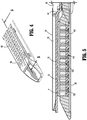
- surgical fastener applier 10 includes a handle assembly 12 and an elongated body 14.
- a disposable loading unit or DLU 16 is releasably secured to a distal end of elongated body 14.
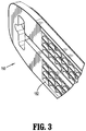
- Disposable loading unit 16 includes a tool assembly 17 having a cartridge assembly 18 housing a plurality of surgical fasteners 120 ( FIG. 2 ) and an anvil assembly 20 movably secured in relation to cartridge assembly 18.
- Disposable loading unit 16 is configured to apply linear rows of surgical fasteners.
- Handle assembly 12 includes a stationary handle member 22, a movable handle member 24, and a barrel portion 26.
- a rotatable member 28 is preferably mounted on the forward end of barrel portion 26 to facilitate rotation of elongated body 14 with respect to handle assembly 12.
- Other surgical fastener appliers of the general type disclosed are disclosed in U.S. Patent Nos. 5,040,715 ; 5,307,976 ; 5,312,023 ; 5,318,221 ; 5,326,013 ; and 5,332,142 .
- tool assembly 17 preferably includes anvil assembly 20 and cartridge assembly 18.
- Anvil assembly 20 includes anvil portion 150 having a plurality of fastener deforming cavities 162 and a cover plate 34 secured to a top surface of anvil portion 150 to define a cavity 36 therebetween.
- Cover plate 34 is provided to prevent pinching of tissue during clamping and firing of surgical fastener applier 10 ( FIG. 1 ).
- Cavity 36 is dimensioned to receive a distal end of a driving member 38 in mechanical communication with the handle assembly 12 ( FIG. 1 ).
- driving member 38 is driven distally through the elongate body 14 ( FIG. 1 ) and translates into a portion of the cavity 36, as shown.
- a camming surface 44 formed on anvil portion 150 is positioned to engage drive member 38 to facilitate clamping of tissue T.
- a pair of pivot members 46 formed on anvil portion 150 is positioned within slots 48 formed in carrier 50 to guide the anvil portion 150 between the open and clamped positions.
- Fastener cartridge 56 includes retention slots 60 for receiving a plurality of fasteners 120 and pushers 140.
- a plurality of spaced apart longitudinal slots 64 extends through fastener cartridge 56 to accommodate upstanding cam wedges 68 of actuation sled 70.
- drive member 38 translates actuation sled 70 through longitudinal slots 64 of fastener cartridge 56 to advance cam wedges 68 into sequential contact with pushers 140, to cause pushers 140 to translate vertically within slots 60 and urge surgical fasteners 120 from slots 60 into the fastener deforming cavities 162 of anvil assembly 20.
- the particular configurations of fasteners 120, pushers 140, and fastener deforming cavities 162 determine the final disposition of fasteners 120 within tissue T, as will be discussed further below.
- fastener forming apparatus 100 includes surgical fasteners 120, pushers 140, and a section of anvil portion 150 having fastener deforming cavities 162. While fastener forming apparatus 100 is integrated into the cartridge assembly 18 ( FIG. 2 ) and anvil assembly 20 ( FIG. 2 ) of surgical fastener applier 10 ( FIG. 2 ) as described above, fastener deforming apparatus 100 will hereafter be discussed with respect to a single surgical fastener 120, pusher 140, and a section of anvil portion 150 containing a pair of fastener deforming cavities 162 for clarity.
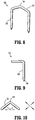
- surgical fastener 120 includes a backspan 122 having a bend 124 along its length. While the bend 124 is shown as being formed in a central portion of the backspan 122, other placements for the bend 124 along the length of backspan 122 are contemplated.
- the bend 124 may be formed by deforming backspan 122 during or after manufacture, or prior to use. Additionally, the bend 124 may be a curve having a radius, as shown, or may be angular, squared, or any desirable shape or cross section.
- the backspan 122 and bend 124 define a horizontal plane "H" ( FIG. 10 ). One or more legs 126 extend outwardly from plane H and the backspan 122.
- legs 126 may extend from backspan 122 such that they are substantially perpendicular to plane H, or may be disposed at an angle with backspan 122. Legs 126 may extend from ends of backspan 122, or may be placed at other locations on the backspan 122. The point at which the legs 126 meet the backspan 122 may generally form a rounded edge or shoulder, as shown.
- the surgical fastener 120 is shown in side view.
- Legs 126 may be straight and have a substantially circular cross-section, or may have any other desirable shape or cross-sectional profile.
- Legs 126 terminate in fastener tips 128.
- Fastener tips 128 may be sharpened points as shown, or may be tapered, blunt, serrated, or have any other desirable configuration.
- backspan 122 can be seen.
- the backspan 122 and bend 124 define an area "A" within plane H that will accommodate portions of legs 126 upon deformation, as will be discussed further below.
- the portions of backspan 122 extending away from bend 124 may be substantially straight and have a circular cross-sectional profile as shown, or may have any other desirable shape or cross-sectional profile.
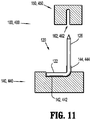
- surgical fastener 120 is shown supported by pusher 140 and opposing a section of anvil portion 150 containing a pair of fastener deforming cavities 162.
- Pusher 140 contains a groove 142 for supporting backspan 122.
- Groove 142 is shaped to accommodate the profile of backspan 122, and will retain the backspan 122 upon motion or moderate lateral shifting, but will disengage from backspan 122 when translated away from backspan 122.
- a forming head 144 is laterally spaced from groove 142 and extends from the surface of pusher 140.
- Forming head 144 includes curved portion 146 that engage legs 126 upon fastener formation, as will be described further below.
- Curved portion 146 extend partially through the proximal portion of pusher 140 such that the distal portion of curved portion 146 approach the distal surface of groove 142.
- the distal portions of curved portion 146 lie substantially level with the groove 142 such that the distal portions of curved portion 146 lie coplanar with and parallel to the backspan 122.
- Anvil portion 150 contains fastener deforming cavities 162 to receive legs 126.
- Fastener deforming cavities 162 have a first end 164 and a second end 166.
- Fastener deforming cavities 162 generally have an arcuate profile, though may have any shape or configuration to accommodate the desired fastener formation.
- the arcuate profile of fastener deforming cavities 162 is such that the first end 164 of each cavity 162 is opposed to a respective curve 146.
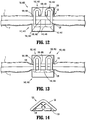
- cam wedges 68 ( FIG. 2 ) cause pushers 140 to translate vertically within slots 60 and urge fasteners 120 toward fastener deforming cavities 162 ( FIG. 12 ) such that legs 126 deform in a manner defined by the profile of fastener deforming cavities 162. Tips 128 ( FIG. 12 ) ultimately exit the second end 166 ( FIG. 12 ) of cavities 162.
- FIGS. 12 and 13 the deformation of fastener 120 is shown.
- the tips 128 and portions of legs 126 again penetrate tissue T and engage curved portion 146 and further deform away from forming head 144.
- the legs 126 approach the proximal portion of the curved portion 146, they diverge and approach the ends of backspan 122 such that they lie parallel to and abut a portion of the backspan 122 in the plane H ( FIG. 10 ).
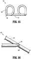
- FIGS. 14 and 15 the fully formed surgical fastener 120 is seen. Portions of the legs 126 lie parallel to and abut the backspan 122 within area A of the horizontal plane H ( FIG. 10 ). The tips 128 of legs 126 face a portion of backspan 122 such that any sharp surfaces of tips 128 are oriented toward the backspan 122 as opposed to surrounding tissue.
- Surgical fastener 220 is substantially similar to surgical fastener 120 described above, but includes a contoured tip 228 that is configured to engage a portion of backspan 222 upon fastener formation as described above.
- Contoured tip 228 may have a fork, a divot, a groove, a ledge, or any suitable configuration to engage a portion of backspan 222.
- the backspan 222 may include a notch 230 to receive contoured tip 228.
- contoured tip 228 and backspan 222 further serves to isolate surrounding tissue from the sharpened surfaces of contoured tip 228, minimizing inadvertent damage and tearing with the natural shifting of tissue.
- fastener forming apparatus may be configured for use in a variety of surgical fastener appliers, such as transverse anastomosis staplers, end-to-end anastomosis staplers, laparoscopic staplers, and transverse anastomosis staplers
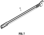
- FIG. 17 illustrates an embodiment of a surgical fastener applier according to the present disclosure, shown generally as surgical fastener applier 310.
- Surgical fastener applier 310 is configured to engage hollow or circular sections of tissue.
- surgical fastener applier 310 may be an annular or, alternatively, circular surgical stapler. Examples of instruments for performing circular tissue fastening operations are described in U.S. Patent Nos. 6,053,390 ; 5,588,579 ; 5,119,987 ; 5,005,749 ; 4,646,745 ; 4,576,167 ; and 4,473,077 .
- Surgical fastener applier 310 includes a handle assembly 330 and an elongate body 340 extending distally from handle assembly 330.
- a tool assembly 317 includes a cartridge assembly 318 and an anvil assembly 320, and is mounted on a distal end of elongate body 340.
- Handle assembly 330 includes a fixed handle 332 and a moveable handle or trigger 334.
- Handle assembly 330 also includes an adjustment knob 336 for moving an anvil assembly 318 relative to cartridge assembly 320.
- the structure and function of handle assembly 330 will only be described herein to the extent necessary to fully disclose the operation of tool assembly 317. It is envisioned that tool assembly 317 may be modified for use with any actuation assembly, powered or manual, and may be capable of two independent actuation strokes.
- the tool assembly 317 may be configured as a removable unit that can be replaced after use, the tool assembly being attached to a handle assembly that includes one or more motors, and/ or computerized control features such as software and/or hardwired logic.
- the cartridge assembly 320 is removable and replaceable and the elongate body can be removable and replaceable in any of these examples. It is further envisioned that the fastener applier provides two or more independent actuation strokes, which may be completed by the same drive member completing two strokes or by two separate drive members.
- Cartridge assembly 318 of tool assembly 317 is operably mounted to a distal end of elongate body 340 of surgical fastener applier 310.
- cartridge assembly 318 is removably secured to elongate body 340 such that cartridge assembly 318, or a portion thereof, may be replaced and surgical fastener applier 310 may be reused.
- only a portion of cartridge assembly 318 is configured to be removed, and subsequently replaced or reloaded.
- surgical fastener applier 310 may be configured for a single use, i.e., disposable.
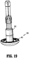
- Cartridge assembly 318 and anvil assembly 320 are interconnected by an anvil shaft 322, as will be described further below.
- cartridge assembly 318 includes a housing 350, a pusher assembly 360A, a surgical fastener cartridge 370, and a knife assembly 380.
- the various parts are inserted through the top of the housing during assembly.
- Knife assembly 380 may be operable to cut or section tissue during operation of surgical fastener applier 310, as is known in the art.
- a proximal end 352a of outer cylindrical portion 352 of housing 350 includes a plurality of tabs 355 formed thereon configured to operably couple cartridge assembly 318 with a distal end of elongate body 340 ( FIG. 17 ).
- a distal end 352b of outer cylindrical portion 352 of housing 350 defines a plurality of recesses 357b formed thereabout configured to receive mounting tabs 374 of surgical fastener cartridge 370.
- Distal end 352b of outer cylindrical portion 352 of housing 350 also defines a slot 357a configured to receive a projection 376 formed on surgical fastener cartridge 370.
- Slot 357a is positioned such that when projection 376 is received in slot 357a, mounting tabs 374 of surgical fastener cartridge 370 are properly aligned with recesses 357b formed in outer cylindrical portion 352 of housing 350.
- Outer cylindrical portion 352 of housing 350 further defines a plurality of openings 359. As will be discussed in further detail below, each of the plurality of openings 359 is configured to engage a pair of a plurality of detents 368a, 368b formed on a distal portion 364 of pusher adaptor 360.
- Pusher assembly 360A includes a pusher adaptor 360 and a pusher member 366.
- Pusher adaptor 360 is a substantially cylindrical member having a proximal portion 362 and a distal portion 364. Proximal portion 362 of pusher adaptor 360 is configured for operable engagement with a drive member (not shown). Distal portion 364 of pusher adaptor 360 is configured to operably engage pusher member 366.
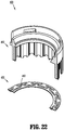
- Surgical fastener cartridge 370 is a substantially cylindrical member configured to operably engage distal end 352b of outer cylindrical portion 352 of housing 350 and defines a longitudinal opening 371.
- Surgical fastener cartridge 370 includes a plurality of surgical fastener receiving pockets 372 disposed about opening 371 arranged in two concentric rows. Surgical fastener receiving pockets 372 align with pushers 440 formed on distal portion 367 of pusher member 366.
- Surgical fastener cartridge 370 includes a plurality of mounting tabs 374 and also includes a protrusion 376. Mounting tabs 374 operably engage surgical fastener cartridge 370 with distal portion 352b formed in outer cylindrical portion 352 of housing 350 and protrusion 376 assures the proper alignment of surgical fastener cartridge 370 with outer cylindrical portion 352 of housing 350.
- Pushers 440 are configured to engage surgical fasteners 120. Accordingly, surgical fasteners 120 are arranged in at least one annular row within cartridge assembly 318. Referring momentarily back to FIG. 8 , surgical fasteners 120 are adapted for use within the circular configuration of surgical fastener applier 310 ( FIG. 17 ) due to the bend 124 in backspan 122. In embodiments, the angle of bend 124 in backspan 122 may be modified to suit the particular needs of implementation of surgical fasteners 120.
- anvil assembly 320 is shown coupled to a distal end of anvil shaft 322.
- Anvil shaft 322 and anvil assembly 320 are configured for engagement with cartridge assembly 318 ( FIG. 17 ) described above.
- a proximal surface of anvil assembly 320 includes a plurality of fastener deforming cavities 462.
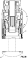
- cartridge assembly 318 is shown in a first or initial condition.
- pusher assembly 360A is received between outer and inner cylindrical portions 352, 354 of housing 350.
- Surgical fastener cartridge 370 is in operative engagement with distal end 350b of housing 350 to operably retain pusher assembly 360A within housing 350.
- pusher assembly 360A In the first or initial position, pusher assembly 360A is prevented from inadvertent distal advancement relative to housing 350 through engagement of the plurality of paired detents 368a, 368b formed on distal portion 364 of pusher adaptor 360 with openings 359 formed in outer cylindrical portion 352 of housing 350.
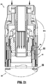
- anvil assembly 320 is approximated toward cartridge assembly 318.
- retraction or actuation of trigger 334 relative to handle 332 causes advancement of a drive assembly (not shown) which operably engages pusher adaptor 360 to cause the advancement of pusher assembly 360A, as indicated by arrows "A".
- Advancement of pusher adaptor 360 advances pusher member 364 thereby causing pusher members 440 on distal portion 367 thereof to be advanced into surgical fastener receiving pockets 372 of surgical fastener cartridge 370 and to eject surgical fasteners 120 from surgical fastener cartridge 370.
- the ejection of surgical fasteners 120 from surgical fastener cartridge 370 causes advancement of surgical fasteners 120 into anvil assembly 320 of anvil to form the surgical fasteners 120, thereby securing tissue between the surgical fastener cartridge 370 and anvil assembly 320.
- Fastener forming apparatus 400 is integrated into the cartridge assembly 318 ( FIG. 17 ) and anvil assembly 320 ( FIG. 17 ) of surgical fastener applier 310 ( FIG. 17 ), and includes the opposed pushers 440 and fastener deforming cavities 462.
- An anvil portion 450 of anvil assembly 320 is defined by a section of anvil assembly 320 containing a pair of fastener deforming cavities 462, as shown.
- Fastener forming apparatus 400 is similar to fastener forming apparatus 100 ( FIG.
- Fastener forming apparatus 400 will hereafter be discussed with respect to a single pusher 440, opposing a section of anvil portion 450 containing a pair of fastener deforming cavities 462 for clarity.
- surgical fastener 120 is shown supported by a pusher 440 and opposing a section of anvil portion 450 containing a pair of fastener deforming cavities 462.
- Pusher 440 contains a groove 442 for supporting backspan 122.
- Groove 442 is shaped to accommodate the profile of backspan 122, and will retain the backspan 122 upon motion or moderate lateral shifting, but will disengage from backspan 122 when translated away from backspan 122.
- a forming head 444 is laterally spaced from groove 442 and extends from the surface of pusher 440.
- Forming head is configured as a protruding member, as shown in FIGS. 11 and 12 .
- Forming head or protruding member 444 includes at least one curved portion 446 (for example, two curved portions 446 are shown) that engage legs 126 upon fastener formation, as will be described further below.
- Curved portion 446 extend partially through the proximal portion of pusher 440 such that the distal portion of curved portion 446 approach the distal surface of groove 442.
- the distal portions of curved portion 446 lie substantially level with the groove 442 such that the distal portions of curved portion 446 lie coplanar with and parallel to the backspan 122.
- the fastener deforming cavities 462 of anvil portion 450 receive legs 126 of surgical fasteners 120.
- Fastener deforming cavities 462 have a first end 464 and a second end 166.
- Fastener deforming cavities 462 generally have an arcuate profile, though may have any shape or configuration to accommodate the desired fastener formation.
- the arcuate profile of fastener deforming cavities 462 is such that the first end 464 of each cavity 462 is opposed to a respective curve 446.
- actuation of handle assembly 330 causes pushers 440 to advance distally through cartridge assembly 320 and eject surgical fasteners 120 distally to penetrate tissue T and enter fastener deforming cavities 462 such that that legs 126 deform in a manner defined by the profile of fastener deforming cavities 462. Tips 128 ( FIG. 8 ) ultimately exit the second end 466 of cavities 162.
- FIGS. 12 and 13 the deformation of fastener 120 is shown.
- the tips 128 and portions of legs 126 again penetrate tissue T and engage curved portion 446 and further deform away from forming head 444.
- the legs 126 approach the proximal portion of the curved portion 146, they diverge and approach the ends of backspan 122.
- legs lie parallel to and abut a portion of the backspan 122 in the plane H.
Landscapes
- Health & Medical Sciences (AREA)
- Life Sciences & Earth Sciences (AREA)
- Surgery (AREA)
- Heart & Thoracic Surgery (AREA)
- Engineering & Computer Science (AREA)
- Biomedical Technology (AREA)
- Nuclear Medicine, Radiotherapy & Molecular Imaging (AREA)
- Medical Informatics (AREA)
- Molecular Biology (AREA)
- Animal Behavior & Ethology (AREA)
- General Health & Medical Sciences (AREA)
- Public Health (AREA)
- Veterinary Medicine (AREA)
- Surgical Instruments (AREA)
Claims (8)
- Bildungsvorrichtung für ein chirurgisches Befestigungsmittel, aufweisend:ein chirurgisches Befestigungsmittel (120), enthaltend;eine Hinterspannung (122) und zumindest einen Schenkel (126), der sich von der Hinterspannung (122) nach außen erstreckt; und eine Bildungsstruktur, enthaltend;einen Amboss (150, 450) mit zumindest einer Aussparung (162, 462), um den zumindest einen Schenkel (126) aufzunehmen; undeinen Schieber (140, 440), der ein vorstehendes Element (144, 444) enthält;dadurch gekennzeichnet, dass die Hinterspannung (122) eine Biegung (124, 424) entlang ihrer Länge hat, wobei die Hinterspannung (122) und Biegung (124, 424) eine horizontale flache Ebene "H" definieren, wobei sich der zumindest eine Schenkel (126) von der Hinterspannung (122) nach außen erstreckt, sodass er rechtwinklig zu der horizontalen Ebene "H" und der Hinterspannung ist,die zumindest eine Aussparung (162, 462) ein bogenförmiges Profil hat, und das hervorstehende Element (144, 444) mit dem zumindest einen Schenkel (126) in Eingriff gelangt,wobei der Amboss (150, 450) und das hervorstehende Element (144, 444) konfiguriert sind zusammenzuwirken, sodass sich ein Abschnitt des zumindest einen Schenkels (126) verformt, um in der horizontalen Ebene "H" zu liegen und an einem Abschnitt der Hinterspannung (122) anzuliegen.
- Bildungsvorrichtung für ein chirurgisches Befestigungsmittel nach Anspruch 1, wobei das hervorstehende Element (144, 444) zumindest einen gekrümmten Abschnitt hat.
- Bildungsvorrichtung für ein chirurgisches Befestigungsmittel nach einem der vorangehenden Ansprüche, wobei der Schieber (140, 440) eine Kerbe (142, 442) zum Aufnehmen der Hinterspannung (122) enthält.
- Bildungsvorrichtung für ein chirurgisches Befestigungsmittel nach einem der vorangehenden Ansprüche, wobei die zumindest eine Aussparung (162, 462) und das hervorstehende Element (144, 444) auf gegenüberliegenden Oberflächen angeordnet sind.
- Bildungsvorrichtung für ein chirurgisches Befestigungsmittel nach einem der vorangehenden Ansprüche, wobei die Biegung (124, 424) in der Hinterspannung (122) den Raum definiert, in dem der zumindest eine Schenkel (126) nach der Bildung angeordnet ist.
- Bildungsvorrichtung für ein chirurgisches Befestigungsmittel nach einem der vorangehenden Ansprüche, wobei ein Abschnitt des zumindest einen Schenkels (126) gestaltet ist, Gewebe zu durchdringen.
- Bildungsvorrichtung für ein chirurgisches Befestigungsmittel nach Anspruch 6, wobei das ferne Ende des zumindest einen Schenkels (126) eine Oberflächengeometrie hat, die konfiguriert ist, mit einem Abschnitt der Hinterspannung (122) in Eingriff zu gelangen.
- Bildungsvorrichtung für ein chirurgisches Befestigungsmittel nach Anspruch 7, wobei die Hinterspannung (122) eine aufnehmende Oberfläche enthält, um mit der Oberflächengeometrie des fernen Endes des zumindest einen Schenkels (126) in Eingriff zu gelangen.
Priority Applications (1)
| Application Number | Priority Date | Filing Date | Title |
|---|---|---|---|
| EP17158323.0A EP3192460B1 (de) | 2012-03-16 | 2013-03-15 | Chirurgische befestigungsvorrichtung mit gerichteter übercrimpung |
Applications Claiming Priority (1)
| Application Number | Priority Date | Filing Date | Title |
|---|---|---|---|
| US13/422,278 US9179913B2 (en) | 2012-03-16 | 2012-03-16 | Surgical fastening apparatus with directed overcrimp |
Related Child Applications (2)
| Application Number | Title | Priority Date | Filing Date |
|---|---|---|---|
| EP17158323.0A Division-Into EP3192460B1 (de) | 2012-03-16 | 2013-03-15 | Chirurgische befestigungsvorrichtung mit gerichteter übercrimpung |
| EP17158323.0A Division EP3192460B1 (de) | 2012-03-16 | 2013-03-15 | Chirurgische befestigungsvorrichtung mit gerichteter übercrimpung |
Publications (3)
| Publication Number | Publication Date |
|---|---|
| EP2638867A2 EP2638867A2 (de) | 2013-09-18 |
| EP2638867A3 EP2638867A3 (de) | 2014-04-16 |
| EP2638867B1 true EP2638867B1 (de) | 2017-05-03 |
Family
ID=47891472
Family Applications (2)
| Application Number | Title | Priority Date | Filing Date |
|---|---|---|---|
| EP13159355.0A Active EP2638867B1 (de) | 2012-03-16 | 2013-03-15 | Chirurgische Befestigungsvorrichtung mit gerichteter Überfaltung |
| EP17158323.0A Active EP3192460B1 (de) | 2012-03-16 | 2013-03-15 | Chirurgische befestigungsvorrichtung mit gerichteter übercrimpung |
Family Applications After (1)
| Application Number | Title | Priority Date | Filing Date |
|---|---|---|---|
| EP17158323.0A Active EP3192460B1 (de) | 2012-03-16 | 2013-03-15 | Chirurgische befestigungsvorrichtung mit gerichteter übercrimpung |
Country Status (5)
| Country | Link |
|---|---|
| US (1) | US9179913B2 (de) |
| EP (2) | EP2638867B1 (de) |
| AU (1) | AU2013201132A1 (de) |
| CA (1) | CA2808099A1 (de) |
| ES (1) | ES2627536T3 (de) |
Families Citing this family (9)
| Publication number | Priority date | Publication date | Assignee | Title |
|---|---|---|---|---|
| WO2015153340A2 (en) * | 2014-03-29 | 2015-10-08 | Standard Bariatrics, Inc. | End effectors surgical stapling devices, and methods of using same |
| CN104116536A (zh) * | 2014-08-20 | 2014-10-29 | 泰戈斯医疗器械(江苏)有限公司 | 钉砧、其制造方法及具有该钉砧的吻合器 |
| CN104546043B (zh) * | 2015-01-19 | 2016-08-31 | 上海逸思医疗科技有限公司 | 一种控弯机构及具有控弯机构的外科器械 |
| CN104546048B (zh) * | 2015-01-19 | 2016-11-16 | 上海逸思医疗科技有限公司 | 一种外科器械及其控弯机构 |
| US10349941B2 (en) * | 2015-05-27 | 2019-07-16 | Covidien Lp | Multi-fire lead screw stapling device |
| US11229433B2 (en) * | 2019-08-09 | 2022-01-25 | Cilag Gmbh International | Linear surgical stapler |
| US20210177402A1 (en) | 2019-12-13 | 2021-06-17 | Dinesh Vyas | Stapler apparatus and methods for use |
| US20230056943A1 (en) * | 2019-12-13 | 2023-02-23 | Dinesh Vyas | Stapler apparatus and methods for use |
| US12290258B2 (en) | 2019-12-13 | 2025-05-06 | Dinesh Vyas | Stapler apparatus and methods for use |
Family Cites Families (33)
| Publication number | Priority date | Publication date | Assignee | Title |
|---|---|---|---|---|
| US4576167A (en) | 1981-09-03 | 1986-03-18 | United States Surgical Corporation | Surgical stapler apparatus with curved shaft |
| US4473077A (en) | 1982-05-28 | 1984-09-25 | United States Surgical Corporation | Surgical stapler apparatus with flexible shaft |
| US4589582A (en) | 1984-08-23 | 1986-05-20 | Senmed, Inc. | Cartridge and driver assembly for a surgical stapling instrument |
| US4805823A (en) | 1988-03-18 | 1989-02-21 | Ethicon, Inc. | Pocket configuration for internal organ staplers |
| US5005749A (en) | 1988-07-01 | 1991-04-09 | United States Surgical Corp. | Anastomosis surgical stapling instrument |
| US5040715B1 (en) | 1989-05-26 | 1994-04-05 | United States Surgical Corp | Apparatus and method for placing staples in laparoscopic or endoscopic procedures |
| US5318221A (en) | 1989-05-26 | 1994-06-07 | United States Surgical Corporation | Apparatus and method for placing staples in laparoscopic or endoscopic procedures |
| JP2714220B2 (ja) | 1990-03-31 | 1998-02-16 | 株式会社東芝 | 換気装置 |
| US5221036A (en) | 1991-06-11 | 1993-06-22 | Haruo Takase | Surgical stapler |
| US5326013A (en) | 1991-10-18 | 1994-07-05 | United States Surgical Corporation | Self contained gas powered surgical apparatus |
| US5307976A (en) | 1991-10-18 | 1994-05-03 | Ethicon, Inc. | Linear stapling mechanism with cutting means |
| US5332142A (en) | 1991-10-18 | 1994-07-26 | Ethicon, Inc. | Linear stapling mechanism with cutting means |
| US5312023A (en) | 1991-10-18 | 1994-05-17 | United States Surgical Corporation | Self contained gas powered surgical apparatus |
| US5350400A (en) * | 1991-10-30 | 1994-09-27 | American Cyanamid Company | Malleable, bioabsorbable, plastic staple; and method and apparatus for deforming such staple |
| US5344059A (en) | 1992-05-19 | 1994-09-06 | United States Surgical Corporation | Surgical apparatus and anvil delivery system therefor |
| US5480089A (en) | 1994-08-19 | 1996-01-02 | United States Surgical Corporation | Surgical stapler apparatus with improved staple pockets |
| CA2146508C (en) | 1994-08-25 | 2006-11-14 | Robert H. Schnut | Anvil for circular stapler |
| US5630540A (en) * | 1995-05-24 | 1997-05-20 | United States Surgical Corporation | Surgical staple and staple drive member |
| US5749896A (en) | 1995-07-18 | 1998-05-12 | Cook; Melvin S. | Staple overlap |
| AU2001288009B2 (en) | 2000-09-08 | 2005-07-07 | Abbott Vascular Inc | Surgical stapler |
| US20040267310A1 (en) | 2000-10-20 | 2004-12-30 | Racenet David C | Directionally biased staple and anvil assembly for forming the staple |
| US6957756B2 (en) * | 2002-04-10 | 2005-10-25 | Illinois Tool Works Inc. | Tool with nosepiece for bending fastener upon installation and fastener therefor |
| US6638297B1 (en) * | 2002-05-30 | 2003-10-28 | Ethicon Endo-Surgery, Inc. | Surgical staple |
| US6953138B1 (en) | 2004-02-18 | 2005-10-11 | Frank W. Dworak | Surgical stapler anvil with nested staple forming pockets |
| US20060291981A1 (en) | 2005-06-02 | 2006-12-28 | Viola Frank J | Expandable backspan staple |
| US7722610B2 (en) * | 2005-06-02 | 2010-05-25 | Tyco Healthcare Group Lp | Multiple coil staple and staple applier |
| EP1912571B1 (de) | 2005-07-27 | 2016-12-21 | Covidien LP | System und verfahren zur bildung von klammertaschen eines chirurgischen klammergeräts |
| ES2372865T3 (es) | 2005-07-27 | 2012-01-27 | Tyco Healthcare Group Lp | Disposición de cavidades receptoras de grapas para grapadora quirúrgica. |
| US7934630B2 (en) | 2005-08-31 | 2011-05-03 | Ethicon Endo-Surgery, Inc. | Staple cartridges for forming staples having differing formed staple heights |
| US8317070B2 (en) | 2005-08-31 | 2012-11-27 | Ethicon Endo-Surgery, Inc. | Surgical stapling devices that produce formed staples having different lengths |
| US8365976B2 (en) * | 2006-09-29 | 2013-02-05 | Ethicon Endo-Surgery, Inc. | Surgical staples having dissolvable, bioabsorbable or biofragmentable portions and stapling instruments for deploying the same |
| US7673782B2 (en) | 2007-03-15 | 2010-03-09 | Ethicon Endo-Surgery, Inc. | Surgical stapling instrument having a releasable buttress material |
| US8186556B2 (en) | 2008-05-09 | 2012-05-29 | Tyco Healthcare Group Lp | Variable compression surgical fastener apparatus |
-
2012
- 2012-03-16 US US13/422,278 patent/US9179913B2/en active Active
-
2013
- 2013-02-25 AU AU2013201132A patent/AU2013201132A1/en not_active Abandoned
- 2013-02-27 CA CA2808099A patent/CA2808099A1/en not_active Abandoned
- 2013-03-15 ES ES13159355.0T patent/ES2627536T3/es active Active
- 2013-03-15 EP EP13159355.0A patent/EP2638867B1/de active Active
- 2013-03-15 EP EP17158323.0A patent/EP3192460B1/de active Active
Also Published As
| Publication number | Publication date |
|---|---|
| US20130240595A1 (en) | 2013-09-19 |
| AU2013201132A1 (en) | 2013-10-03 |
| ES2627536T3 (es) | 2017-07-28 |
| US9179913B2 (en) | 2015-11-10 |
| CA2808099A1 (en) | 2013-09-16 |
| EP3192460B1 (de) | 2025-01-01 |
| EP2638867A2 (de) | 2013-09-18 |
| EP3192460A1 (de) | 2017-07-19 |
| EP2638867A3 (de) | 2014-04-16 |
Similar Documents
| Publication | Publication Date | Title |
|---|---|---|
| EP2638867B1 (de) | Chirurgische Befestigungsvorrichtung mit gerichteter Überfaltung | |
| US8091756B2 (en) | Varying tissue compression using take-up component | |
| EP2116198B1 (de) | Unterschiedliche Gewebekompression mit Ambosskonfiguration | |
| EP2110084B1 (de) | Chirurgische Befestigungsvorrichtung mit einzelner Schlaufe zur Anwendung einer variablen Kompression | |
| EP2311387B1 (de) | Unterschiedliche Gewebekompression mit Unterstützung elastischer Elemente | |
| CN101883528B (zh) | 能够供给缝钉的内切割器 | |
| EP2314230B1 (de) | Dissektionsspitze und Inserter für ein chirurgisches Instrument | |
| EP2682061B1 (de) | T-Nut-Kippamboss für kreisförmiges Klammerinstrument | |
| EP2116197B1 (de) | Kartusche mit variabler Kompression für chirurgische Kompressionshalter | |
| EP3130292A1 (de) | Kartusche mit variabler kompression für chirurgische kompressionshalter | |
| WO2013151827A1 (en) | Surgical stapler with staples of different sizes | |
| EP2992832B1 (de) | Vorrichtungen zur ermöglichung des ausstosses von chirurgischen befestigungselementen aus magazinen |
Legal Events
| Date | Code | Title | Description |
|---|---|---|---|
| PUAI | Public reference made under article 153(3) epc to a published international application that has entered the european phase |
Free format text: ORIGINAL CODE: 0009012 |
|
| AK | Designated contracting states |
Kind code of ref document: A2 Designated state(s): AL AT BE BG CH CY CZ DE DK EE ES FI FR GB GR HR HU IE IS IT LI LT LU LV MC MK MT NL NO PL PT RO RS SE SI SK SM TR |
|
| AX | Request for extension of the european patent |
Extension state: BA ME |
|
| PUAL | Search report despatched |
Free format text: ORIGINAL CODE: 0009013 |
|
| AK | Designated contracting states |
Kind code of ref document: A3 Designated state(s): AL AT BE BG CH CY CZ DE DK EE ES FI FR GB GR HR HU IE IS IT LI LT LU LV MC MK MT NL NO PL PT RO RS SE SI SK SM TR |
|
| AX | Request for extension of the european patent |
Extension state: BA ME |
|
| RIC1 | Information provided on ipc code assigned before grant |
Ipc: A61B 17/072 20060101AFI20140311BHEP Ipc: A61B 17/064 20060101ALN20140311BHEP |
|
| 17P | Request for examination filed |
Effective date: 20141003 |
|
| RBV | Designated contracting states (corrected) |
Designated state(s): AL AT BE BG CH CY CZ DE DK EE ES FI FR GB GR HR HU IE IS IT LI LT LU LV MC MK MT NL NO PL PT RO RS SE SI SK SM TR |
|
| 17Q | First examination report despatched |
Effective date: 20150623 |
|
| RIC1 | Information provided on ipc code assigned before grant |
Ipc: A61B 17/064 20060101ALN20160805BHEP Ipc: A61B 17/072 20060101AFI20160805BHEP |
|
| GRAP | Despatch of communication of intention to grant a patent |
Free format text: ORIGINAL CODE: EPIDOSNIGR1 |
|
| STAA | Information on the status of an ep patent application or granted ep patent |
Free format text: STATUS: GRANT OF PATENT IS INTENDED |
|
| INTG | Intention to grant announced |
Effective date: 20161115 |
|
| GRAS | Grant fee paid |
Free format text: ORIGINAL CODE: EPIDOSNIGR3 |
|
| GRAA | (expected) grant |
Free format text: ORIGINAL CODE: 0009210 |
|
| STAA | Information on the status of an ep patent application or granted ep patent |
Free format text: STATUS: THE PATENT HAS BEEN GRANTED |
|
| AK | Designated contracting states |
Kind code of ref document: B1 Designated state(s): AL AT BE BG CH CY CZ DE DK EE ES FI FR GB GR HR HU IE IS IT LI LT LU LV MC MK MT NL NO PL PT RO RS SE SI SK SM TR |
|
| REG | Reference to a national code |
Ref country code: GB Ref legal event code: FG4D |
|
| REG | Reference to a national code |
Ref country code: AT Ref legal event code: REF Ref document number: 889064 Country of ref document: AT Kind code of ref document: T Effective date: 20170515 Ref country code: CH Ref legal event code: EP |
|
| REG | Reference to a national code |
Ref country code: IE Ref legal event code: FG4D |
|
| REG | Reference to a national code |
Ref country code: DE Ref legal event code: R096 Ref document number: 602013020495 Country of ref document: DE |
|
| REG | Reference to a national code |
Ref country code: ES Ref legal event code: FG2A Ref document number: 2627536 Country of ref document: ES Kind code of ref document: T3 Effective date: 20170728 |
|
| REG | Reference to a national code |
Ref country code: NL Ref legal event code: MP Effective date: 20170503 |
|
| REG | Reference to a national code |
Ref country code: AT Ref legal event code: MK05 Ref document number: 889064 Country of ref document: AT Kind code of ref document: T Effective date: 20170503 |
|
| REG | Reference to a national code |
Ref country code: LT Ref legal event code: MG4D |
|
| PG25 | Lapsed in a contracting state [announced via postgrant information from national office to epo] |
Ref country code: NO Free format text: LAPSE BECAUSE OF FAILURE TO SUBMIT A TRANSLATION OF THE DESCRIPTION OR TO PAY THE FEE WITHIN THE PRESCRIBED TIME-LIMIT Effective date: 20170803 Ref country code: HR Free format text: LAPSE BECAUSE OF FAILURE TO SUBMIT A TRANSLATION OF THE DESCRIPTION OR TO PAY THE FEE WITHIN THE PRESCRIBED TIME-LIMIT Effective date: 20170503 Ref country code: LT Free format text: LAPSE BECAUSE OF FAILURE TO SUBMIT A TRANSLATION OF THE DESCRIPTION OR TO PAY THE FEE WITHIN THE PRESCRIBED TIME-LIMIT Effective date: 20170503 Ref country code: AT Free format text: LAPSE BECAUSE OF FAILURE TO SUBMIT A TRANSLATION OF THE DESCRIPTION OR TO PAY THE FEE WITHIN THE PRESCRIBED TIME-LIMIT Effective date: 20170503 Ref country code: GR Free format text: LAPSE BECAUSE OF FAILURE TO SUBMIT A TRANSLATION OF THE DESCRIPTION OR TO PAY THE FEE WITHIN THE PRESCRIBED TIME-LIMIT Effective date: 20170804 Ref country code: FI Free format text: LAPSE BECAUSE OF FAILURE TO SUBMIT A TRANSLATION OF THE DESCRIPTION OR TO PAY THE FEE WITHIN THE PRESCRIBED TIME-LIMIT Effective date: 20170503 |
|
| PG25 | Lapsed in a contracting state [announced via postgrant information from national office to epo] |
Ref country code: NL Free format text: LAPSE BECAUSE OF FAILURE TO SUBMIT A TRANSLATION OF THE DESCRIPTION OR TO PAY THE FEE WITHIN THE PRESCRIBED TIME-LIMIT Effective date: 20170503 Ref country code: IS Free format text: LAPSE BECAUSE OF FAILURE TO SUBMIT A TRANSLATION OF THE DESCRIPTION OR TO PAY THE FEE WITHIN THE PRESCRIBED TIME-LIMIT Effective date: 20170903 Ref country code: LV Free format text: LAPSE BECAUSE OF FAILURE TO SUBMIT A TRANSLATION OF THE DESCRIPTION OR TO PAY THE FEE WITHIN THE PRESCRIBED TIME-LIMIT Effective date: 20170503 Ref country code: RS Free format text: LAPSE BECAUSE OF FAILURE TO SUBMIT A TRANSLATION OF THE DESCRIPTION OR TO PAY THE FEE WITHIN THE PRESCRIBED TIME-LIMIT Effective date: 20170503 Ref country code: SE Free format text: LAPSE BECAUSE OF FAILURE TO SUBMIT A TRANSLATION OF THE DESCRIPTION OR TO PAY THE FEE WITHIN THE PRESCRIBED TIME-LIMIT Effective date: 20170503 Ref country code: PL Free format text: LAPSE BECAUSE OF FAILURE TO SUBMIT A TRANSLATION OF THE DESCRIPTION OR TO PAY THE FEE WITHIN THE PRESCRIBED TIME-LIMIT Effective date: 20170503 Ref country code: BG Free format text: LAPSE BECAUSE OF FAILURE TO SUBMIT A TRANSLATION OF THE DESCRIPTION OR TO PAY THE FEE WITHIN THE PRESCRIBED TIME-LIMIT Effective date: 20170803 |
|
| PG25 | Lapsed in a contracting state [announced via postgrant information from national office to epo] |
Ref country code: CZ Free format text: LAPSE BECAUSE OF FAILURE TO SUBMIT A TRANSLATION OF THE DESCRIPTION OR TO PAY THE FEE WITHIN THE PRESCRIBED TIME-LIMIT Effective date: 20170503 Ref country code: RO Free format text: LAPSE BECAUSE OF FAILURE TO SUBMIT A TRANSLATION OF THE DESCRIPTION OR TO PAY THE FEE WITHIN THE PRESCRIBED TIME-LIMIT Effective date: 20170503 Ref country code: DK Free format text: LAPSE BECAUSE OF FAILURE TO SUBMIT A TRANSLATION OF THE DESCRIPTION OR TO PAY THE FEE WITHIN THE PRESCRIBED TIME-LIMIT Effective date: 20170503 Ref country code: SK Free format text: LAPSE BECAUSE OF FAILURE TO SUBMIT A TRANSLATION OF THE DESCRIPTION OR TO PAY THE FEE WITHIN THE PRESCRIBED TIME-LIMIT Effective date: 20170503 Ref country code: EE Free format text: LAPSE BECAUSE OF FAILURE TO SUBMIT A TRANSLATION OF THE DESCRIPTION OR TO PAY THE FEE WITHIN THE PRESCRIBED TIME-LIMIT Effective date: 20170503 |
|
| REG | Reference to a national code |
Ref country code: DE Ref legal event code: R097 Ref document number: 602013020495 Country of ref document: DE |
|
| REG | Reference to a national code |
Ref country code: FR Ref legal event code: PLFP Year of fee payment: 6 |
|
| PG25 | Lapsed in a contracting state [announced via postgrant information from national office to epo] |
Ref country code: SM Free format text: LAPSE BECAUSE OF FAILURE TO SUBMIT A TRANSLATION OF THE DESCRIPTION OR TO PAY THE FEE WITHIN THE PRESCRIBED TIME-LIMIT Effective date: 20170503 |
|
| PLBE | No opposition filed within time limit |
Free format text: ORIGINAL CODE: 0009261 |
|
| STAA | Information on the status of an ep patent application or granted ep patent |
Free format text: STATUS: NO OPPOSITION FILED WITHIN TIME LIMIT |
|
| 26N | No opposition filed |
Effective date: 20180206 |
|
| PG25 | Lapsed in a contracting state [announced via postgrant information from national office to epo] |
Ref country code: SI Free format text: LAPSE BECAUSE OF FAILURE TO SUBMIT A TRANSLATION OF THE DESCRIPTION OR TO PAY THE FEE WITHIN THE PRESCRIBED TIME-LIMIT Effective date: 20170503 |
|
| PGFP | Annual fee paid to national office [announced via postgrant information from national office to epo] |
Ref country code: IE Payment date: 20180221 Year of fee payment: 6 |
|
| REG | Reference to a national code |
Ref country code: CH Ref legal event code: PL |
|
| PG25 | Lapsed in a contracting state [announced via postgrant information from national office to epo] |
Ref country code: MC Free format text: LAPSE BECAUSE OF FAILURE TO SUBMIT A TRANSLATION OF THE DESCRIPTION OR TO PAY THE FEE WITHIN THE PRESCRIBED TIME-LIMIT Effective date: 20170503 |
|
| REG | Reference to a national code |
Ref country code: BE Ref legal event code: MM Effective date: 20180331 |
|
| PG25 | Lapsed in a contracting state [announced via postgrant information from national office to epo] |
Ref country code: LU Free format text: LAPSE BECAUSE OF NON-PAYMENT OF DUE FEES Effective date: 20180315 |
|
| PG25 | Lapsed in a contracting state [announced via postgrant information from national office to epo] |
Ref country code: BE Free format text: LAPSE BECAUSE OF NON-PAYMENT OF DUE FEES Effective date: 20180331 Ref country code: CH Free format text: LAPSE BECAUSE OF NON-PAYMENT OF DUE FEES Effective date: 20180331 Ref country code: LI Free format text: LAPSE BECAUSE OF NON-PAYMENT OF DUE FEES Effective date: 20180331 |
|
| PGFP | Annual fee paid to national office [announced via postgrant information from national office to epo] |
Ref country code: ES Payment date: 20190401 Year of fee payment: 7 |
|
| PG25 | Lapsed in a contracting state [announced via postgrant information from national office to epo] |
Ref country code: IE Free format text: LAPSE BECAUSE OF NON-PAYMENT OF DUE FEES Effective date: 20190315 Ref country code: MT Free format text: LAPSE BECAUSE OF NON-PAYMENT OF DUE FEES Effective date: 20180315 |
|
| PG25 | Lapsed in a contracting state [announced via postgrant information from national office to epo] |
Ref country code: TR Free format text: LAPSE BECAUSE OF FAILURE TO SUBMIT A TRANSLATION OF THE DESCRIPTION OR TO PAY THE FEE WITHIN THE PRESCRIBED TIME-LIMIT Effective date: 20170503 |
|
| PG25 | Lapsed in a contracting state [announced via postgrant information from national office to epo] |
Ref country code: PT Free format text: LAPSE BECAUSE OF FAILURE TO SUBMIT A TRANSLATION OF THE DESCRIPTION OR TO PAY THE FEE WITHIN THE PRESCRIBED TIME-LIMIT Effective date: 20170503 Ref country code: HU Free format text: LAPSE BECAUSE OF FAILURE TO SUBMIT A TRANSLATION OF THE DESCRIPTION OR TO PAY THE FEE WITHIN THE PRESCRIBED TIME-LIMIT; INVALID AB INITIO Effective date: 20130315 |
|
| PG25 | Lapsed in a contracting state [announced via postgrant information from national office to epo] |
Ref country code: CY Free format text: LAPSE BECAUSE OF FAILURE TO SUBMIT A TRANSLATION OF THE DESCRIPTION OR TO PAY THE FEE WITHIN THE PRESCRIBED TIME-LIMIT Effective date: 20170503 Ref country code: MK Free format text: LAPSE BECAUSE OF NON-PAYMENT OF DUE FEES Effective date: 20170503 |
|
| PG25 | Lapsed in a contracting state [announced via postgrant information from national office to epo] |
Ref country code: AL Free format text: LAPSE BECAUSE OF FAILURE TO SUBMIT A TRANSLATION OF THE DESCRIPTION OR TO PAY THE FEE WITHIN THE PRESCRIBED TIME-LIMIT Effective date: 20170503 |
|
| PGFP | Annual fee paid to national office [announced via postgrant information from national office to epo] |
Ref country code: IT Payment date: 20210217 Year of fee payment: 9 |
|
| PGFP | Annual fee paid to national office [announced via postgrant information from national office to epo] |
Ref country code: GB Payment date: 20210219 Year of fee payment: 9 |
|
| REG | Reference to a national code |
Ref country code: ES Ref legal event code: FD2A Effective date: 20210804 |
|
| PG25 | Lapsed in a contracting state [announced via postgrant information from national office to epo] |
Ref country code: ES Free format text: LAPSE BECAUSE OF NON-PAYMENT OF DUE FEES Effective date: 20200316 |
|
| GBPC | Gb: european patent ceased through non-payment of renewal fee |
Effective date: 20220315 |
|
| PG25 | Lapsed in a contracting state [announced via postgrant information from national office to epo] |
Ref country code: GB Free format text: LAPSE BECAUSE OF NON-PAYMENT OF DUE FEES Effective date: 20220315 |
|
| PG25 | Lapsed in a contracting state [announced via postgrant information from national office to epo] |
Ref country code: IT Free format text: LAPSE BECAUSE OF NON-PAYMENT OF DUE FEES Effective date: 20220315 |
|
| PGFP | Annual fee paid to national office [announced via postgrant information from national office to epo] |
Ref country code: DE Payment date: 20250218 Year of fee payment: 13 |
|
| PGFP | Annual fee paid to national office [announced via postgrant information from national office to epo] |
Ref country code: FR Payment date: 20250219 Year of fee payment: 13 |