EP2638751B1 - Verfahren und vorrichtung zur zusammengesetzte meldung von drahtloser relaisleistungskapazität - Google Patents
Verfahren und vorrichtung zur zusammengesetzte meldung von drahtloser relaisleistungskapazität Download PDFInfo
- Publication number
- EP2638751B1 EP2638751B1 EP11741310.4A EP11741310A EP2638751B1 EP 2638751 B1 EP2638751 B1 EP 2638751B1 EP 11741310 A EP11741310 A EP 11741310A EP 2638751 B1 EP2638751 B1 EP 2638751B1
- Authority
- EP
- European Patent Office
- Prior art keywords
- link
- relay node
- backhaul
- access
- relay
- Prior art date
- Legal status (The legal status is an assumption and is not a legal conclusion. Google has not performed a legal analysis and makes no representation as to the accuracy of the status listed.)
- Not-in-force
Links
- 238000000034 method Methods 0.000 title claims description 69
- 239000002131 composite material Substances 0.000 title 1
- 238000007726 management method Methods 0.000 claims description 18
- 230000005540 biological transmission Effects 0.000 claims description 13
- 238000012545 processing Methods 0.000 claims description 11
- 238000004891 communication Methods 0.000 claims description 9
- 238000013468 resource allocation Methods 0.000 claims description 3
- 230000002776 aggregation Effects 0.000 description 29
- 238000004220 aggregation Methods 0.000 description 29
- 239000000969 carrier Substances 0.000 description 24
- 238000005516 engineering process Methods 0.000 description 13
- 241000700159 Rattus Species 0.000 description 11
- 238000013459 approach Methods 0.000 description 10
- 230000004044 response Effects 0.000 description 10
- 230000008569 process Effects 0.000 description 9
- 238000010586 diagram Methods 0.000 description 7
- 230000011664 signaling Effects 0.000 description 6
- JZEPSDIWGBJOEH-UHFFFAOYSA-N 4-decylbicyclo[2.2.1]hept-2-ene Chemical compound C1CC2C=CC1(CCCCCCCCCC)C2 JZEPSDIWGBJOEH-UHFFFAOYSA-N 0.000 description 4
- 241000760358 Enodes Species 0.000 description 4
- 230000006870 function Effects 0.000 description 4
- 238000013439 planning Methods 0.000 description 4
- 238000001228 spectrum Methods 0.000 description 4
- 235000008694 Humulus lupulus Nutrition 0.000 description 3
- 230000008901 benefit Effects 0.000 description 3
- 230000008859 change Effects 0.000 description 3
- 238000005259 measurement Methods 0.000 description 3
- 230000004048 modification Effects 0.000 description 3
- 238000012986 modification Methods 0.000 description 3
- 230000006872 improvement Effects 0.000 description 2
- 238000012423 maintenance Methods 0.000 description 2
- 230000009286 beneficial effect Effects 0.000 description 1
- 238000002955 isolation Methods 0.000 description 1
- 230000007774 longterm Effects 0.000 description 1
- 239000000203 mixture Substances 0.000 description 1
- 230000001105 regulatory effect Effects 0.000 description 1
Images


Classifications
-
- H—ELECTRICITY
- H04—ELECTRIC COMMUNICATION TECHNIQUE
- H04W—WIRELESS COMMUNICATION NETWORKS
- H04W52/00—Power management, e.g. Transmission Power Control [TPC] or power classes
- H04W52/04—Transmission power control [TPC]
- H04W52/38—TPC being performed in particular situations
- H04W52/46—TPC being performed in particular situations in multi-hop networks, e.g. wireless relay networks
-
- H—ELECTRICITY
- H04—ELECTRIC COMMUNICATION TECHNIQUE
- H04W—WIRELESS COMMUNICATION NETWORKS
- H04W52/00—Power management, e.g. Transmission Power Control [TPC] or power classes
- H04W52/04—Transmission power control [TPC]
- H04W52/30—Transmission power control [TPC] using constraints in the total amount of available transmission power
- H04W52/34—TPC management, i.e. sharing limited amount of power among users or channels or data types, e.g. cell loading
-
- H—ELECTRICITY
- H04—ELECTRIC COMMUNICATION TECHNIQUE
- H04W—WIRELESS COMMUNICATION NETWORKS
- H04W52/00—Power management, e.g. Transmission Power Control [TPC] or power classes
- H04W52/04—Transmission power control [TPC]
- H04W52/30—Transmission power control [TPC] using constraints in the total amount of available transmission power
- H04W52/36—Transmission power control [TPC] using constraints in the total amount of available transmission power with a discrete range or set of values, e.g. step size, ramping or offsets
- H04W52/365—Power headroom reporting
-
- H—ELECTRICITY
- H04—ELECTRIC COMMUNICATION TECHNIQUE
- H04W—WIRELESS COMMUNICATION NETWORKS
- H04W52/00—Power management, e.g. Transmission Power Control [TPC] or power classes
- H04W52/04—Transmission power control [TPC]
- H04W52/06—TPC algorithms
- H04W52/14—Separate analysis of uplink or downlink
- H04W52/143—Downlink power control
-
- H—ELECTRICITY
- H04—ELECTRIC COMMUNICATION TECHNIQUE
- H04W—WIRELESS COMMUNICATION NETWORKS
- H04W52/00—Power management, e.g. Transmission Power Control [TPC] or power classes
- H04W52/04—Transmission power control [TPC]
- H04W52/06—TPC algorithms
- H04W52/14—Separate analysis of uplink or downlink
- H04W52/146—Uplink power control
-
- H—ELECTRICITY
- H04—ELECTRIC COMMUNICATION TECHNIQUE
- H04W—WIRELESS COMMUNICATION NETWORKS
- H04W52/00—Power management, e.g. Transmission Power Control [TPC] or power classes
- H04W52/04—Transmission power control [TPC]
- H04W52/30—Transmission power control [TPC] using constraints in the total amount of available transmission power
- H04W52/36—Transmission power control [TPC] using constraints in the total amount of available transmission power with a discrete range or set of values, e.g. step size, ramping or offsets
- H04W52/367—Power values between minimum and maximum limits, e.g. dynamic range
Definitions
- the present invention relates generally to the management of relay nodes in wireless communication networks, and more particularly relates to techniques for reporting power capabilities for relay nodes to facilitate wireless network resource management.
- a relay node is used to receive and re-transmit/forward signals intended for user equipments (UEs) in a mobile network.
- UEs user equipments
- a number of UEs can be served by a relay.
- the primary objective of the relay node is to enhance the coverage in the uplink and downlink.
- the relay architecture comprises a RN connected wirelessly to a "donor cell," which is served by a “donor base station (known as a donor eNode B, or DeNB, in 3GPP terminology).
- the wireless connection between the RN and the DeNB is referred to as the radio backhaul link.
- UEs connect to the RN via a radio access link that is identical (at least from the UE's perspective) to the radio access link used by UEs to access a conventional eNB.
- the backhaul link (DeNB-RN link) and access link (RN-UE link) are termed as the Un and Uu interfaces respectively.
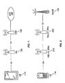
- the connection between different nodes when RN is used is shown on Figure 1 .
- UE 110 is connected to RN 120 via the Uu interface, while RN 120 is connected to eNB 130 (the donor eNode B) via the Un interface.
- eNB 130 is connected to the Evolved Packet Core (EPC) 140 using the standard interfaces developed by 3GPP.
- EPC Evolved Packet Core
- the RN may be fixed or movable. Both of these types of RN are wireless RN in that they receive and transmit wireless signals over the access and backhaul links.
- a "fixed" RN is stationary or immovable.
- the generic term RN or relay is used throughout this document.
- a movable RN may be implemented as a standalone mobile relay, i.e., as a wireless device dedicated to operation as an RN.
- a wireless terminal that is capable of providing end-user services, whether to a user or to a machine, such as in a machine-to-machine context, may also act as a relay.
- a mobile relay may be deployed in a moving vehicle such as a bus, train, ferry, or the like, in which case it may primarily serve UEs that are aboard the movable vehicle. However, a moving mobile relay may also serve UEs in surrounding areas.
- FIG. 1 depicts a single hop relay architecture, the details of which are currently being specified by 3GPP for LTE networks.
- LTE does not specify multi-hop capability for relays.
- one extension of the relay technique is to deploy multiple relay nodes between the served UE and the eNB.
- Multi-hop relays are well known in other communications contexts. Information sent to the UE from the fixed network "hops" from the donor base station through multiple RNs, until it reaches the UE. In a similar manner information sent from the UE traverses multiple RN on the way to the donor base station.
- a multi-hop relay system may comprise any or several of the various types of relays discussed above, including fixed relays, movable relays or a combination of fixed and movable relays.
- a fixed relay might be used for the first hop while a movable relay is the used for the second hop, or vice-versa.
- Figure 2 illustrates the multi-hop relay concept based on two hops, as it might appear in an LTE network.
- UE 110 communicates with RN 210, over the Uu interface.
- RN 210 in turn communicates with RN 220, which finally communicates with DeNB 130, over the Un interface.
- a single- or multi-hop relay system can be employed in any system, e.g., a High-Speed Packet Access (HSPA) network (i.e., UTRA FDD and UTRA TDD), GSM (including GERAN/EDGE), 3GPP2 CDMA technologies (e.g., CDMA2000 and HRPD) or a multi-radio-access-technology (multi-RAT) carrier aggregation (CA) system such as HSPA-LTE CA, etc.
- HSPA High-Speed Packet Access
- GSM including GERAN/EDGE
- 3GPP2 CDMA technologies e.g., CDMA2000 and HRPD
- multi-RAT multi-radio-access-technology
- CA carrier aggregation
- Relay architectures similar to those shown in Figures 1 and 2 may also be employed in other technologies such as in HSPA FDD/TDD, GSM/GERAN, CDMA2000/HRPD, WiMax etc.
- the relay architecture may be slightly different in other technologies.
- a RN is connected via backhaul link to any type of donor base station (e.g., belonging to HSPA, GSM, CDMA200, WiMax technology etc).
- Figure 3 illustrates a possible relay architecture for an HSPA network.
- a UE310 is connected to an RN 320 that supports HSPA services.
- RN 320 is connected to the Node B 330, which in turn is connected to a radio network controller (RNC) 340, via the lub interface.
- RNC radio network controller
- WO 2008/084371 A2 discloses a relay network comprising relay nodes with access links towards UEs, and a method for power control.
- the method comprises determining a UE specific downlink data transmission power level for the relay station to transmit data to the UE.
- the power level is determined based on a channel measurement report received from the UE.
- a relay node may be designed to have different maximum output power capabilities for the access and backhaul links.
- a relay node's maximum output power in each of the backhaul and access links may depend on several factors, such as the selected frequency/frequency band for each of the access and backhaul links, typical operating temperature, available power sources, local emission requirements, and so on.
- a relay node reports its output power capability to the donor base station or other network nodes separately for the backhaul and access links, which may have different maximum output power.
- a network node such as a donor base station, an Operations & Maintenance (O&M) node, an Operational Support Systems (OSS) node, a Self-Organizing Network (SON) node, or the like, may be configured to request the relay node to report its backhaul link and access link output power class capabilities or maximum output powers or rated output powers to the network node, and then to receive the reported capabilities in response.
- the report may specify a per-antenna transmit power capability; this may be specifically requested in some cases.
- the received relay node power-class capability information for the backhaul and access links may then be used for one or several network management functions, such as radio resources management (e.g., admission control of users in access link), network planning/dimensioning, etc.
- a relay node may be configured to report its backhaul link and access link output power class capabilities or maximum output powers or rated output powers to a network node, such as a donor base station, an O&M node, an OSS node, a SON node, etc. Again, this report may indicate per-antenna port capabilities, rather than (or in addition to) total output power capabilities. In some cases, this reporting may be in response to request; in others, the report may be responsive to an attachment to the network or some other triggering event.
- a network node such as a donor base station, an O&M node, an OSS node, a SON node, etc.
- this report may indicate per-antenna port capabilities, rather than (or in addition to) total output power capabilities. In some cases, this reporting may be in response to request; in others, the report may be responsive to an attachment to the network or some other triggering event.
- Relay node and base station node apparatus corresponding generally to the methods summarized above are also disclosed, and include processing circuits configured to carry out one or more of the techniques described herein for signaling and processing reference signal identification information.
- processing circuits configured to carry out one or more of the techniques described herein for signaling and processing reference signal identification information.
- eNB and UE should be considered in their broadest senses as applied to the principles of the invention.
- the described techniques may be applied to other wireless networks, of various topologies and radio technologies.
- the term “user equipment” or “UE” should be interpreted broadly, to include various types of radio access equipment (radio devices used to access a wireless network) including cell phones, fixed wireless terminals, wireless adapters for use with portable computers, wireless access devices built into or intended for use with laptop computers, tablet computers, and the like, as well as wireless access devices used in so-called machine-to-machine (M2M) applications.
- M2M machine-to-machine
- the discussion that follows may use the terms evolved NodeB, Node B, DeNB, and the like, those terms should be understood broadly to apply to any base station or other wireless network access point configured according to the inventive techniques.
- the operation of a wireless relay node can be classified into two categories with respect to usage of the radio spectrum.
- the first category is the "in-band relay."
- the backhaul link and the access link operate using the same carrier frequency.
- the communication over the backhaul and access links are time-domain multiplexed.
- simultaneous operation over the two links may also be possible provided sufficient isolation between the access and backhaul links are achieved, e.g., by the virtue of directive transmission, or by introducing another multiplexing technique such as code-division multiplexing.
- the second category is the "out-of-band” or "out-band relay.”
- the backhaul link and the access link operate using different carrier frequencies, i.e., the backhaul and the access link are separated in the frequency domain.
- the carrier frequencies may belong to the same general radio frequency band, or to completely different frequency bands.
- CA carrier aggregation
- LTE Long Term Evolution
- CA carrier aggregation
- CA in LTE is expected to provide up to 100 MHz of bandwidth to a single UE.
- CA may be used in the radio downlink, uplink, or in both directions.
- Carrier aggregation technology is also called (e.g., interchangeably called) "multi-carrier systems", “multi-carrier operation”, and/or “multi-carrier” transmission and/or reception.
- the component carriers in carrier aggregation belong to the same technology (e.g., all are either WCDMA or LTE).
- carrier aggregation between carriers of different technologies may also be used to increase data throughput.
- the carriers from WCDMA and LTE may be aggregated.
- Another example is the aggregation of LTE and CDMA2000 carriers.
- Carrier aggregation between carriers of different technologies is also referred to as "multi-RAT carrier aggregation" or “multi-RAT-multi-carrier system” or simply “inter-RAT carrier aggregation”.
- carrier aggregation within the same technology may be regarded as 'intra-RAT' or simply 'single RAT' carrier aggregation.
- a first general case is continuous carrier aggregation; a second general case is non-continuous carrier aggregation.
- continuous carrier aggregation the available component carriers are adjacent to each other, e.g., adjacent to one another in the same frequency band.
- non-continuous carrier aggregation the aggregated component carriers are separated along the frequency band.
- Non-continuous carrier aggregation technique provides a practical approach to enable mobile network operators to fully utilize their (often scattered) spectrum resources.
- Non-continuous carrier aggregation deployments are typically further categorized as (1) multiple (non-contiguous) component carriers that are separated such that they belong to different frequency bands, and (2) multiple (non-contiguous) component carriers that are within the same frequency band.
- a hybrid CA deployment may include two or more adjacent carriers in one frequency band (e.g., band A) and one or more contiguous or non-contiguous carriers in another frequency band (e.g., band B).
- CA may also be used in relay environment to increase the data rate over the backhaul and/or access links.
- carrier aggregation may be used in both in-band and out-band relays.
- relay node Often, more than one relay node is connected to the same donor base station.
- the relays are generally deployed in the coverage area of the donor cell. Since the primary function of relay node is for coverage improvement, both outdoor and indoor relay deployment scenarios are beneficial under various circumstances. For instance, an outdoor relay can be used for improvement of cell edge coverage.
- the indoor relay on the other hand, might be used for addressing indoor dead spots, or serving indoor hot spots.
- the antennas used for the backhaul and access links may either be in the indoors or outdoors.
- any combination of indoor/outdoor antennas and indoor/outdoor relay is possible in principle.
- the same or different MIMO configurations may be used in the access link and the backhaul link.
- a relay may use two transmit and two receive antennas for the access link, and four transmit and four receive antennas on the backhaul link.
- FIGs 4A-4C Examples of three relay deployment scenarios are illustrated in Figures 4A-4C .
- the relay 120 is deployed outdoors; all the relay antennas for the transmission and reception of signals over the backhaul and access links are also located in the outdoors.
- the outdoor relay 120 serves outdoor and indoor users.
- the relay 120 is deployed indoors; all the relay antennas for the transmission and reception of signals over the backhaul and access links are also located in the indoors.
- the indoor relay 120 primarily serves indoor users.
- Figure 4C the relay 120 is deployed indoors.
- the relay antennas for the transmission and reception of signals over the backhaul link are located outdoor. However the antennas for the access link are located indoors.
- This type of relay deployment is also called a Truwall (through wall, or thru-wall), and is usually meant to primarily serve the indoor users.
- the use of outdoor backhaul antennas results in improved backhaul link quality, e.g., compared to pure indoor deployment.
- deployment scenarios are not limited to the three scenarios illustrated in Figures 4A-4C .
- multiple antennas may be used for receive and/or transmit operations on either or both of the access and backhaul links; still further, the number of antennas used for transmit and receive transmits may differ in any given relay 120, as may the number of antennas used for the access link and the backhaul link.
- a relay node may also be a multi-standard radio (MSR).
- MSR relay contains common radio frequency (RF) components (e.g., power amplifiers, RF filters) which can be used selectively to operate simultaneously with more than one RAT or using more than one carrier within the same RAT.
- RF radio frequency
- the MSR relay may also be termed a multi-carrier, multi-standard radio (MC-MSR) base station, due to the fact that it may sometimes support a single RAT, with more than one carrier.
- MC-MSR multi-carrier, multi-standard radio
- a single-RAT MSR is a special case of the MSR.
- a single-RAT MSR relay may support one or more carriers of the same RAT.
- another special case of a MSR relay is a relay that supports a single carrier within a RAT, i.e., single-carrier, single-RAT MSR relay.
- a multi-carrier single-RAT MSR relay supports more than one carrier of the same RAT.
- a single-RAT MSR relay may differ from a conventional (non-MSR) single-RAT relay due to differences in some of the radio requirements.
- the MSR node has generic radio requirements.
- the MSR relay may support frequency-division duplexing (FDD) or time-division duplexing (TDD).
- FDD frequency-division duplexing
- TDD time-division duplexing
- Examples of RATs that might be supported in a FDD MSR relay are: LTE FDD, UTRA FDD and GSM. Another example is: LTE FDD and 3GPP2 CDMA technologies (e.g., CDMA200 and HRPD). Examples of RATs that might be supported in a TDD MSR relay are: LTE TDD and UTRA TDD.
- the carriers within a FDD or TDD MSR relay may be contiguous or non-contiguous. Furthermore such relay may be used in single hop or in multiple hop relay system. It will be appreciated that all of the techniques disclosed herein for managing relay nodes in wireless networks apply to relays of any of the types discussed above, including relay nodes that are based on the MSR principle.
- the relays may be designed to have different maximum output power in the access part from the maximum output power for the backhaul part. This means the available maximum output power can be different on the access and backhaul links.
- a relay node's maximum output power in each of the backhaul and access links may also depend upon additional factors (i.e., beyond the deployment scenario/environment) such as the selected frequency/frequency band for each of the access and backhaul links, typical operating temperature, available power sources (connected to wall, backup batteries, generator etc.), local emission requirements (e.g., regulatory and/or safety limitations), etc.
- a relay node's maximum output power for transmitting over the access link and the backhaul link is the same. For example, the maximum output power of 30 dBm is assumed for backhaul and access link transmission.
- the maximum output power i.e., the power class
- no explicit signaling to indicate the power class for each link is necessary.
- the relay node's maximum output powers may lead to inefficient relay operation. For instance, it may lead to over-allocation or underutilization of resources in the backhaul and access links.
- a relay node reports its output power capability to the donor base station (or other relevant network nodes) separately for the backhaul and access links, which may have different maximum output power.
- a network node such as a donor base station, an Operations & Maintenance (O&M) node, an Operational Support Systems (OSS) node, a Self-Organizing Network (SON) node, or the like, may be configured to request the relay node to report its backhaul link and access link output power class capabilities or maximum output powers or rated output powers to the network node, and then to receive the reported capabilities in response.
- the report may specify a per-antenna transmit power capability; this may be specifically requested in some cases.
- the received relay node power-class capability information for the backhaul and access links may then be used for one or several network management functions, such as radio resources management (e.g., admission control of users in access link), network planning/dimensioning, etc.
- a relay node may be configured to report its backhaul link and access link output power class capabilities or maximum output powers or rated output powers to a network node, such as a donor base station, an O&M node, an OSS node, a SON node, etc. Again, this report may indicate per-antenna port capabilities, rather than (or in addition to) total output power capabilities. In some cases, this reporting may be in response to request; in others, the report may be responsive to an attachment to the network or some other triggering event.
- a network node such as a donor base station, an O&M node, an OSS node, a SON node, etc.
- this report may indicate per-antenna port capabilities, rather than (or in addition to) total output power capabilities. In some cases, this reporting may be in response to request; in others, the report may be responsive to an attachment to the network or some other triggering event.
- the end relay may report its output power capability (access link, backhaul links) to the donor node via intermediate relay either transparently, such that the intermediate relay is unaware of the reports, or non-transparently, such that the intermediate relay node is aware of the reports.
- the relay node is able to report its output power capability to the donor base station (or other relevant network nodes) separately for backhaul and access links, as these links may have different maximum output power capabilities. It is also possible that a given relay node has different lowest or minimum output power capabilities for the access and backhaul links. For the purposes of discussion, these parameters are denoted as follows:
- Another approach is relative power reporting.
- the objective of this approach is to reduce the signaling overhead compared to the absolute power reporting approach.
- the relay node reports to the network node the absolute value of its maximum output power capability for one link (which can be either the backhaul link or the access link, provided only that the network node receiving the report is aware of the order) and a relative power metric for the second link, where the relative power metric indicates the relative power capability of the second link with respect to the power capability of the first link.
- the relay node may report its power capability for the backhaul and access links with respect to a pre-defined reference value (PREF).
- PREF pre-defined reference value
- the reference value may be different for the maximum output power (Pmax_REF) and minimum output power (Pmax_REF).
- the reference value may also be different for the backhaul (Pmax_REF_BL / Pmin_REF_BL) and access links (Pmax_REF_AL / Pmin_REF_AL).
- the reference values may correspond to the maximum and minimum output powers of the donor base stations (e.g., the donor eNode B in LTE).
- Another approach to reporting power capabilities is to report a scenario identifier that represents a particular combination of output power capabilities, rather than individually reporting the capabilities.
- An objective of this approach to reporting is to reduce the signaling overheads compared to the relative and absolute power reporting methods.
- pre-defined tables defining the backhaul and access links power capability, relative to a set of scenario identifiers can be defined in a standard, or are otherwise known to both the relay node and the network node that receives the report.
- Table 1 illustrates one way of pre-defining the relay output power capability in a standard.
- the relay supporting a particular capability can report the identifier corresponding to its capability to the network nodes.
- the table can be updated in case a relay node with new power class is standardized. This means few extra bits should be reserved for the future scenarios, e.g., 4 bits for Table 1 rather than 2 bits assuming 12 additional scenarios may be added in future releases.
- Table 1 Example of relay maximum output power scenarios Scenario ID Relay maximum output power [dBm] Backhaul link Access link 1 24 24 2 30 30 3 24 30 4 30 24
- Table 2 shows another method of pre-defining its output power capability in the standard.
- the difference is that the relay power class in terms of its deployment scenario (e.g., indoor) is defined.
- the relay supporting a particular capability can report the identifier corresponding to its capability to the network nodes.
- the table can also be updated in case a relay node with new power class / deployment type is standardized. Hence few extra bits should be reserved for the future scenarios, e.g., four bits rather than three bits, assuming that up to ten additional scenarios may be added in future releases.
- Table 2 Example of relay maximum output power Scenario ID Relay type Relay maximum output power [dBm] Backhaul link Access link 1 Outdoor # 1 30 30 2 Outdoor # 2 30 24 3 Indoor # 1 30 24 4 Indoor # 2 30 20 5 Truwall # 1 24 24 6 Truwall # 2 24 20
- Pre-defined tables similar to those illustrated in Tables 1 and 2 but containing the minimum output power for backhaul and access links along with their scenario identifiers, can also be standardized. Using such a pre-defined table, a relay may be configured to report a separate identifier corresponding to its minimum output power capability.
- the relay node reports its total maximum and/or minimum output power capability for the backhaul and the access links.
- a relay node may also support multi-antenna transmission techniques, such as transmit diversity, MIMO, etc.
- a relay node may also (or instead) report its maximum and/or minimum output power capabilities on a per-antenna-port basis, for one or both of the backhaul link and the access links.
- the relay node may use any of the principles for reporting per antenna output power capability outlined above, such as relative power reporting and/or the use of scenario identifiers.
- a relay node may be configured to report its total and/or per-antenna maximum and/or minimum output power capabilities for the backhaul and the access links for each carrier or component carrier in carrier aggregation (which may be intra-RAT or inter-RAT CA).
- the relay node may support carrier aggregation or may employ multiple carriers for different links (i.e., which are not used for carrier aggregation).
- Different carriers on the same type of link e.g., on backhaul link
- may support different maximum output power e.g., different power depending upon the frequency band or depending on the radio access technology.
- the relay node reports maximum / minimum total and/or per antenna port power capability for each supported carrier.
- a relay node may report the output power of one of the carriers (e.g., power of primary or anchor carrier in CA) and one bit indicating that all other carriers have the same output power capability.
- the set of signaled information can be specific to each of the backhaul and access links. Furthermore, a separate set of information can be signaled for each of the maximum and minimum output power capabilities, for each type of link (i.e., for the backhaul and access links).
- any of the relay nodes described above may be pre-configured to automatically report its power capabilities, for example, in response to certain triggering events such as attachment to the donor node, a re-start of the relay node, etc.
- a suitable network node may configure or request the relay node to report its output power capability for the backhaul and access links.
- Examples of the network nodes that might send configuration information or a request to the relay node are a base station (particularly the donor base station), such as an eNode B in LTE or a Node B in HSPA, a network controller, such as the Radio Network Controller (RNC) in HSPA or a base station controller (BSC) in GSM, a self organizing network (SON) node, an operation and management node, a core network node, such as the Mobility Management Entity in LTE, or even a positioning node, such as the evolved Serving Mobile Location Center (E-SMLC) in LTE, and so on.
- a base station particularly the donor base station
- a network controller such as the Radio Network Controller (RNC) in HSPA or a base station controller (BSC) in GSM
- RNC Radio Network Controller
- BSC base station controller
- SON self organizing network
- E-SMLC evolved Serving Mobile Location Center
- the network node may request the relay to report its power capability either during an initial setup (i.e., when a new relay node is added) or when the relay node output power capability of the existing relay node is modified (e.g., upgraded or downgraded).
- the network node may also request the relay node to report its power capability at any other time, such as whenever it suspects the relay node capability has been modified or when configuration information has been lost.
- the network node may also specify the specific principles (as described) to be used by the relay for reporting its power capability, such as whether the relay node should report its capabilities in absolute power terms, relative power terms, etc.
- the network node may also explicitly request whether the relay reports all of its power capability information or only specific information, such as total power or power per antenna port, for one or both of the backhaul and access links, etc.
- the relay may use pre-defined rules to report the power capability and all information as specified in pre-defined rules.
- the relay may be preprogrammed with these pre-defined rules, or the pre-defined rules may be sent to the relay node in the field, by a network node, for subsequent use.
- the relay node As described above, there is a wide range of flexibility in how the relay node is configured, and in particular with respect to which network node configures the relay node and which relay node receives and uses the reported capability information.
- the donor base station e.g., donor eNB in LTE
- configures the relay node which in turn reports its output power capability to the donor BS over the backhaul link (e.g., over the Un interface in LTE).
- the backhaul link e.g., over the Un interface in LTE
- a relay node may use any of the principles outlined above to report its output power capability to a suitable network node. As noted above, this reporting may be autonomous, in some cases, or may be in response to explicit requests. Thus, some of the circumstances under which a relay node may be configured to report its output power capabilities to the network node include, but are not limited to:
- the various embodiments described above enable a given network node (e.g., the donor base station) to acquire the maximum / minimum output power capabilities of the relay node, for each or both of the backhaul and access links.
- This acquired relay output power capability information may also be signaled to other network nodes. For example, assume that the donor base station acquires the relay power capability information from the relay node.
- the donor base station may signal this information to one or more other nodes, such as another BS (e.g., to another eNodeB, over the X2 interface in LTE), another relay node, an O&M node, a SON node, a core network node (e.g., MME in LTE), or a positioning node (e.g., E-SMLC in LTE or SAS node in HSPA).
- another BS e.g., to another eNodeB, over the X2 interface in LTE
- another relay node e.g., an O&M node
- a SON node e.g., a core network node (e.g., MME in LTE)
- a positioning node e.g., E-SMLC in LTE or SAS node in HSPA.
- the source node represents any network node that receives the relay output power capability information:
- the acquired relay output power capability information for the backhaul and the access links can be used by various network nodes for several different purposes, such as radio network management (such as for resource allocation, load balaricing, admission control, etc.), network/cell planning or dimensioning, etc.
- radio network management such as for resource allocation, load balaricing, admission control, etc.
- network/cell planning or dimensioning etc.
- the donor base station e.g., a donor eNB in LTE
- the donor base station can use the relay access link power output capability information for determining the number of users that can potentially be admitted in the access part.
- the donor base station may also use this information to perform load balancing, i.e., in distributing users among several different relay nodes.
- the donor base station may also determine the coverage of the relay and may further use this information to determine the number of relay nodes required to cover the donor base station's coverage area.
- the donor base station may use the backhaul output power capability in determining the amount of data that can be transmitted by the relay over the backhaul link.
- the donor base station may assign the relay to use appropriate antenna modes, modulation and coding schemes or format for transmission over the backhaul link, based on the reported power capabilities.
- SON and O&M nodes may further use the relay power capability in dimensioning the suitable number of relay nodes required in the given environment.
- Positioning nodes such as a positioning node in LTE (known as the Evolved Serving Mobile Location Center, or E-SMLC), may use the relay access link output power capability to determine the power of the positioning reference signals (PRS) that are used by the UE for performing positioning measurements, such as Reference Signal Time Difference (RSTD) measurements.
- PRS positioning reference signals
- RSTD Reference Signal Time Difference
- the donor base station may request the end relay (e.g., relay node 210 in Figure 2 ) as well as the intermediate relay (e.g., relay node 220 in Figure 2 ) to report their output power capability for each link, i.e., their respective access links and backhaul links.
- end relay e.g., relay node 210 in Figure 2
- intermediate relay e.g., relay node 220 in Figure 2
- an end relay node can be configured by the donor node to report its output power capabilities (for backhaul and access link) either transparently, such that the intermediate relay is not aware of the request, or non-transparently, such that the intermediate node is aware of the request.
- the intermediate relay nodes may also request the end relay to report its output power capabilities.
- the donor node may also separately lower the max output power of the access and backhaul links.
- the end relay output power capabilities may also be reported to other network nodes, e.g., to other base stations, positioning nodes, etc., as described above.
- An intermediate relay node may have multiple links to other relays.
- the intermediate relay may also be serving users, i.e., it may have an access link for use by mobile stations.
- the intermediate relay may also be a standalone or dedicated node acting only as a relay. In that case, it may have only backhaul links.
- the intermediate relay may have different maximum output power capabilities for different links: backhaul links and access link.
- the max output power on some of the links may be the same, e.g., the same maximum output power of the access link and backhaul link between end relay and intermediate relay, while the other backhaul link, i.e., between relay and donor node, may have a different maximum output power.
- a few examples of different combination of relay output power classes over different links are illustrated in tables 3, 4 and 5.
- Table 3 Relay maximum output powers (dBm) in multi-hop - same max power levels in access link and hop#1 Scenario ID Relay maximum output power [dBm] Backhaul link (RN1-RN2)-hop#1 Backhaul link (RN2-DeNB)-hop#2 Access link 1 24 24 24 2 30 30 30 3 30 24 30 4 24 30 24 Table 4: Relay maximum output powers (dBm) in multi-hop- same max power levels in hop#2 and hop#1 Scenario ID Relay maximum output power [dBm] Backhaul link (RN1-RN2)-hop#1 Backhaul link (RN2-DeNB)-hop#2 Access link - 1 24 24 24 2 30 30 30 3 24 24 30 4 30 30 24 Table 5: Relay maximum output powers (dBm) in multi-hop - different max power levels in all links Scenario ID Relay maximum output power [dBm] Backhaul link (RN1-RN2)-hop#1 Backhaul link (RN2-DeNB)-hop#2 Access link 1 24 24
- the intermediate relay node may be configured to report its maximum (and/or minimum) output power for each link, such as for each backhaul link and access link, to the donor node or to another relay node, such as a relay node that is acting as a donor node to the intermediate node.
- the reporting of output power capability information to the donor node or other relay node can be done transparently, i.e., such that other intermediate nodes or relays are not aware of the reports, or non-transparently.
- the reporting of the output power capabilities per link may take place in response to a request received from other nodes, e.g., donor node, other relays or other network nodes (e.g., positioning node etc).
- the reporting of the maximum output power per link may be sent by the intermediate relay to other nodes proactively, i.e., without receiving any explicit request, such as at the time of setup, reconfiguration, modification of one or more parameters.
- the intermediate relay node may use any of the principles described in previous sections to report its output power capabilities to the donor node or to other relays or to other nodes.
- the donor node may also be able to lower the maximum output power of the intermediate relay node for each link below the maximum output power capability separately, for example, in the event that the load / traffic is small or the cell size is small.
- the techniques may also be used for the reporting of other types of relay capabilities for the backhaul and the access links.
- additional relay capabilities include multi-antenna capabilities, uplink and/or downlink bandwidths, a supported number of resource blocks in the uplink and/or downlink, and so on. Many of these additional capabilities may differ for the backhaul and access links, and thus the reporting scheme for the separate capabilities to be reported.
- Examples of a multi-antenna capability include the number of supported antennas, supported MIMO/antenna modes (e.g., transmit diversity or spatial time diversity etc), etc. Reporting of additional capabilities may also include whether or not the relay supports carrier aggregation on the backhaul and access links.
- the relay may also indicate additional carrier aggregation capability information for backhaul and access links, such as whether the carrier aggregation is intra-RAT, inter-RAT, contiguous or non-contiguous, whether the carrier aggregation is in the uplink or downlink or both, and so on.
- the donor node may independently configure the relay's maximum output power below its maximum output power capability, separately on the backhaul and access links. For example, assume that the relay supports 24 dBm maximum output power over the backhaul link and 30 dBm maximum output power over the access link. In a particular system, the donor node may be configured so that it can send instructions to the relay node to lower the maximum output powers of the backhaul and access links to 10 dBm and 20 dBm, respectively.
- the techniques described herein are applicable to any type of RAT (LTE, HSPA, GSM, CDMA2000, HRPD, Wimax etc), and are also application to a relay node supporting a mixture of RATs (e.g., a multi-standard radio relay).
- the MSR or non-MSR relay may support contiguous carriers or non-contiguous carriers.
- the techniques are also applicable to relays that support carrier aggregation or multi-carrier operation or multi-carrier-multi-RAT operation.
- the techniques are also applicable to wireless relays, e.g., mobile relays, which are typically deployed in the movable vehicle to mainly serve users in the vehicle or a wireless terminal acting as a relay etc.
- Figures 5, 6, and 7 illustrate process flows corresponding to several of these techniques, as applied in several of the nodes described above. All of these process flow diagrams illustrate methods for managing network nodes in a wireless communication network that includes a wireless relay node for wirelessly transmitting signals to and wireless receiving signals from one or more user equipments (UEs), or to and from one or more other relay nodes, or to and from one or more of both, via an access link, and for wirelessly transmitting signals to and wirelessly receiving signals from a donor base station, via a backhaul link.
- UEs user equipments
- FIG. 5 illustrates a process flow implemented by a donor node, such as the donor base station, or some other node "behind" the donor base station.
- this process optionally begins with the sending of a request for a power capability report.
- some relay nodes may be configured to report power capabilities autonomously, without an explicit request by the donor node.
- the request may specify a type of power capability to report, or specify a reporting format, or both.
- the node receives the power capability report from the relay node, the report indicating a first backhaul-link output-power capability and a first access-link output-power capability for the relay node.
- these indicated first capabilities can comprise different values.
- the reported information may be in any of a wide variety of formats, and may include various details.
- the indicated first backhaul-link output-power capability and first access-link output-power capability are both one of the following: a power class for the relay node for the corresponding link; a maximum output power for the relay node for the corresponding link; a rated output power for the relay node for the corresponding link; and a minimum output power for the relay node for the corresponding link.
- at least one of the indicated first backhaul-link output-power capability and first access-link output-power capability is reported as a relative value.
- one of the indicated first backhaul-link output-power capability and first access-link output-power capability is reported as a relative value that indicates an offset from the other of the indicated first backhaul-link output-power capability and first access-link output-power capability.
- both of the indicated first backhaul-link output-power capability and first access-link output-power capability are reported as relative values that indicate an offset from a corresponding pre-defined reference value.
- the report received from the relay node includes a scenario identifier that identifies one of a pre-determined set of combinations of access-link and backhaul-link output-power capabilities.
- at least one of the indicated first backhaul-link output-power capability and first access-link output-power capability corresponds to a first antenna port of the relay node, and the report further indicates a second backhaul-link output-power capability or a second access-link output-power capability, or both, for a second antenna port of the relay node.
- At least one of the indicated first backhaul-link output-power capability and first access-link output-power capability correspond to a first component carrier in a corresponding multi-carrier link
- the report further indicates a second backhaul-link output-power capability or a second access-link output-power capability, or both, for a second component carrier of the corresponding multi-carrier link.
- the power capability report is received directly from the relay node (via a backhaul link), while in others the power capability report may be received via forwarding by some intermediate node, such as a donor base station or an intermediate relay node.
- the power capability information received from the relay node is applied in one or more network management tasks.
- These network management tasks include, but are not limited to, any of the following: network resource allocation; network load balancing; admission control; determining the coverage of the relay node; determining the number of relay nodes required to cover the coverage area of the donor base station; determining a data capacity for a link; assigning antenna modes or modulation and coding schemes, or both; determining a transmission format for the backhaul link; and determining the power of a positioning reference signal.
- Network management tasks may also include configuring the relay maximum output power separately for the backhaul and access links, without exceeding the reported capabilities, e.g., by signaling power limits to the relay node.
- Figure 6 illustrates a process flow implemented by a relay node, whether a relay node communicating directly with a donor base station or a relay node connected to the network core through one or more intermediate relay nodes.
- the illustrated process begins with the receiving of a request for a power capability report.
- the request may specify a type of power capability to report, or specify a reporting format, or both.
- the relay node transmits the power capability report to the network, as shown at block 620.
- the report indicates a first backhaul-link output-power capability and a first access-link output-power capability for the relay node. Again, these indicated first capabilities can comprise different values.
- the reported information may be in any of a wide variety of formats, and may include various details.
- the indicated first backhaul-link output-power capability and first access-link output-power capability are both one of the following: a power class for the relay node for the corresponding link; a maximum output power for the relay node for the corresponding link; a rated output power for the relay node for the corresponding link; and a minimum output power for the relay node for the corresponding link.
- at least one of the indicated first backhaul-link output-power capability and first access-link output-power capability is reported as a relative value.
- one of the indicated first backhaul-link output-power capability and first access-link output-power capability is reported as a relative value that indicates an offset from the other of the indicated first backhaul-link output-power capability and first access-link output-power capability.
- both of the indicated first backhaul-link output-power capability and first access-link output-power capability are reported as relative values that indicate an offset from a corresponding pre-defined reference value.
- the report transmitted from the relay node includes a scenario identifier that identifies one of a pre-determined set of combinations of access-link and backhaul-link output-power capabilities.
- at least one of the indicated first backhaul-link output-power capability and first access-link output-power capability corresponds to a first antenna port of the relay node, and the report further indicates a second backhaul-link output-power capability or a second access-link output-power capability, or both, for a second antenna port of the relay node.
- At least one of the indicated first backhaul-link output-power capability and first access-link output-power capability correspond to a first component carrier in a corresponding multi-carrier link
- the report further indicates a second backhaul-link output-power capability or a second access-link output-power capability, or both, for a second component carrier of the corresponding multi-carrier link.
- the power capability report is sent only from the relay node to the donor base station (via a backhaul link), while in others the power capability report may be forwarded to the target node via forwarding by some intermediate node, such as a donor base station or an intermediate relay node.
- the report request illustrated at block 610 is only one of several possible events that might trigger a report.
- some relay nodes may be configured to report power capabilities autonomously, without an explicit request by the donor node.
- a relay node might be configured to transmit a power capability report in response to a change in a backhaul-link output-power capability or an access-link output-power capability, or both.
- the same relay node or a different embodiment might be configured to transmit the report upon power-up of the relay node, or upon re-establishment of a link by the relay node, or both.
- FIG. 7 An example of this approach is shown in Figure 7 .
- a change in power capability is detected by the node.
- a power capability report reflecting this change, is transmitted to the network as shown at block 720.
- the procedure in Figure 7 is similar to the one described in connection with Figure 6 , and is subject to any of the same modifications and variants.
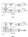
- Figures 8 and 9 illustrate elements of an example relay node and example donor eNodeB, respectively. These devices can be configured to carry out one or more of the corresponding methods described above.
- the relay node 800 pictured in Figure 8 includes processing circuits 810 in addition to backhaul radio 840 and access radio 850.
- Each of the backhaul radio 840 and access radio 850 may use one or several antennas (e.g., for MIMO operation).
- backhaul radio 840 has N antennas, 860-1 to 860-N, while access radio 850 has M antennas, 870-1 to 870-M. In some cases one or more of these antennas may be shared by transmit and receive functions.
- Processing circuits 810 comprise a microprocessor 820 and memory 830.
- Microprocessor 820 is configured with appropriate program code 832 for carrying out one or several of the reporting and configuration techniques described above.
- memory 830 which may comprise several types of memory, includes storage for link parameters 834, which includes data indicating the maximum and/or minimum radio powers for the backhaul and access links.
- donor eNodeB 900 has a similar general configuration to that of relay node 800. However, in addition to processing circuits 910, donor eNodeB comprises an eNodeB radio 940 (for communicating with relay node 800 and with one or more UEs) and a network interface 950, which provides a link to the fixed portion of the telecommunications network, including, in some embodiments, other donor eNodeBs. As was the case with the relay node of Figure 8 , the eNodeB radio 940 may use one or several antennas (e.g., for MIMO operation). The illustrated embodiment has Q antennas, labeled 960-1 to 960-Q. Again, in some cases one or more of these antennas may be shared for transmit and receive operation.
- eNodeB radio 940 may use one or several antennas (e.g., for MIMO operation).
- the illustrated embodiment has Q antennas, labeled 960-1 to 960-Q. Again, in some cases one or more of these antennas may be shared
- Processing circuits 910 comprise at least one microprocessor 920 and memory 930.
- Microprocessor 930 is configured with appropriate program code 932 for carrying out one or several of the reporting and configuration techniques described above.
- Memory 930 which may comprise several types of memory, also includes storage for link parameters 934, which includes data indicating the maximum and/or minimum radio powers for the backhaul and access links of one or more relay NodeBs.
- base station is used herein to refer to a collection of functional elements (one of which is a radio transceiver that communicates wirelessly with one or more mobile stations), which may or may not be implemented as a single physical unit.
- the techniques and apparatus described above enable a relay node to report separate maximum and/or minimum output power capabilities to the donor BS or to other network nodes, for each of the access link and backhaul link supported by the relay node.
- the reported backhaul and access link power capability information can be used for various purposes, such as radio resource management, network planning / dimensioning etc. Knowing the available power in the access part of the relay can be used for determining how many users to admit to the relay. This information can be further used, for example, to determine whether users can or should be handed over from or to the donor base station from the relay node.
Landscapes
- Engineering & Computer Science (AREA)
- Computer Networks & Wireless Communication (AREA)
- Signal Processing (AREA)
- Mobile Radio Communication Systems (AREA)
Claims (17)
- Verfahren zur Verwaltung von Netzknoten in einem drahtlosen Kommunikationsnetz, das einen drahtlosen Relaisknoten zum drahtlosen Übertragen von Signalen an und zum drahtlosen Empfangen von Signalen von eine(r) oder mehrere(n) Benutzereinrichtungen, UEs, oder an und von einen/einem oder mehrere(n) andere(n) Relaisknoten oder an und von einen/einem oder mehrere(n) von beiden über eine Anschlussstrecke und zum drahtlosen Übertragen von Signalen an und zum drahtlosen Empfangen von Signalen von eine(r) Geber-Basisstation über eine Backhaulstrecke aufweist, wobei das Verfahren umfasst: in einem Netzknoten erfolgendes
Empfangen (520) einer Meldung vom Relaisknoten, die eine erste Anschlussstrecken-Ausgangsleistungskapazität für den Relaisknoten angibt,
wobei das Verfahren dadurch gekennzeichnet ist, dass die empfangene Meldung auch eine erste Backhaulstrecken-Ausgangsleistungskapazität für den Relaisknoten angibt, wobei die angegebenen ersten Kapazitäten unterschiedliche Werte umfassen; und dass das Verfahren umfasst:Anwenden (530) der angegebenen ersten Kapazitäten in einem oder mehreren Netzverwaltungsprozessen. - Verfahren nach Anspruch 1, wobei die angegebene erste Backhaulstrecken-Ausgangsleistungskapazität und erste Anschlussstrecken-Ausgangsleistungskapazität eines von Folgenden sind:eine Leistungsklasse für den Relaisknoten für die entsprechende Verbindungsstrecke;eine maximale Ausgangsleistung für den Relaisknoten für die entsprechende Verbindungsstrecke;eine Nennausgangsleistung für den Relaisknoten für die entsprechende Verbindungsstrecke; undeine minimale Ausgangsleistung für den Relaisknoten für die entsprechende Verbindungsstrecke.
- Verfahren nach Anspruch 1 oder 2, wobei mindestens eines als relativer Wert gemeldet wird, nämlich die angegebene erste Backhaulstrecken-Ausgangsleistungskapazität und/oder erste Anschlussstrecken-Ausgangsleistungskapazität.
- Verfahren nach Anspruch 1 oder 2, wobei die vom Relaisknoten empfangene Meldung eine Szenario-Kennung umfasst, die eine von einem vorbestimmten Satz von Kombinationen aus Anschlussstrecken- und Backhaulstrecken-Ausgangsleistungskapazitäten bezeichnet.
- Verfahren nach einem der Ansprüche 1 bis 4, wobei mindestens eines, nämlich die angegebene erste Backhaulstrecken-Ausgangsleistungskapazität und/oder erste Anschlussstrecken-Ausgangsleistungskapazität einem ersten Antennenport des Relaisknotens entspricht und wobei die vom Relaisknoten empfangene Meldung ferner eine zweiten Backhaulstrecken-Ausgangsleistungskapazität oder eine zweite Anschlussstrecken-Ausgangsleistungskapazität oder beides für einen zweiten Antennenport des Relaisknotens angibt und wobei das Verfahren ferner umfasst: Anwenden der angegebenen zweiten Kapazitäten in einem oder mehreren Netzverwaltungsprozessen.
- Verfahren nach einem der Ansprüche 1 bis 5, wobei mindestens eines, nämlich die angezeigte erste Backhaulstrecken-Ausgangsleistungskapazität und/oder erste Anschlussstrecken-Ausgangsleistungskapazität einer ersten Trägerkomponente auf einer entsprechenden Mehrträgerverbindungsstrecke entspricht und wobei die vom Relaisknoten empfangene Meldung ferner eine zweite Backhaulstrecken-Ausgangsleistungskapazität oder eine zweite Anschlussstrecken-Ausgangsleistungskapazität oder beides für eine zweite Trägerkomponente der entsprechenden Mehrträgerverbindungsstrecke angibt und wobei das Verfahren ferner umfasst: Anwenden der angegebenen zweiten Kapazitäten in einem oder mehreren Netzverwaltungsprozessen.
- Verfahren nach einem der Ansprüche 1 bis 6, ferner dadurch gekennzeichnet, dass es umfasst: anfängliches Auffordern (510) des Relaisknotens, die Meldung bereitzustellen.
- Verfahren nach einem der Ansprüche 1 bis 7, wobei das Anwenden (530) der angegebenen ersten Kapazitäten in einem oder mehreren Netzverwaltungsprozessen umfasst: Verwenden der angegebenen ersten Kapazitäten bei einem oder mehreren von Folgendem:Netzressourcenzuteilung;Netzlastausgleich;Zugangskontrolle;Bestimmen des Versorgungsbereichs des Relaisknotens;Bestimmen der Anzahl von Relaisknoten, die zur Versorgung des Versorgungsbereichs der Geber-Basisstation erforderlich ist;Bestimmen einer Datenkapazität für eine Verbindungsstrecke;Zuweisen von Antennenmodi oder Modulations- und Codierungsschemen oder von beiden;Bestimmen eines Übertragungsformats für die Backhaulstrecke;Bestimmen der Leistung eines Positionierungsreferenzsignals; undKonfigurieren der maximalen Relaisausgangsleistung getrennt für die Backhaul- und Anschlussstrecken, ohne die ersten Kapazitäten zu überschreiten.
- Verfahren zur Verwaltung von Netzknoten in einem drahtlosen Kommunikationsnetz, das einen drahtlosen Relaisknoten zum drahtlosen Übertragen von Signalen an und zum drahtlosen Empfangen von Signale von eine(r) oder mehrere(n) Benutzereinrichtungen, UEs, oder an und von einen/einem oder mehrere(n) andere(n) Relaisknoten oder an und von einen/einem oder mehrere(n) von beiden über eine Anschlussstrecke und zum drahtlosen Übertragen von Signalen an und zum drahtlosen Empfangen von Signalen von eine(r) Geber-Basisstation über eine Backhaulstrecke, wobei das Verfahren umfasst: in einem Relaisknoten erfolgendes
Übertragen (620) einer Meldung, die eine erste Anschlussstrecken-Ausgangsleistungskapazität für den Relaisknoten angibt, über die Backhaulstrecke,
wobei das Verfahren dadurch gekennzeichnet ist, dass die übertragene Meldung auch eine erste Backhaulstrecken-Ausgangsleistungskapazität für den Relaisknoten umfasst, wobei die angegebenen ersten Kapazitäten unterschiedliche Werte umfassen. - Verfahren nach Anspruch 9, wobei die angegebene erste Backhaulstrecken-Ausgangsleistungskapazität und erste Anschlussstrecken-Ausgangsleistungskapazität eines von Folgenden sind:eine Leistungsklasse für den Relaisknoten für die entsprechende Verbindungsstrecke;eine maximale Ausgangsleistung für den Relaisknoten für die entsprechende Verbindungsstrecke;eine Nennausgangsleistung für den Relaisknoten für die entsprechende Verbindungsstrecke; undeine minimale Ausgangsleistung für den Relaisknoten für die entsprechende Verbindungsstrecke.
- Verfahren nach Anspruch 9 oder 10, wobei mindestens eines als relativer Wert gemeldet wird, nämlich die angegebene erste Backhaulstrecken-Ausgangsleistungskapazität und erste Anschlussstrecken-Ausgangsleistungskapazität.
- Verfahren nach Anspruch 9 oder 10, wobei die Meldung eine Szenario-Kennung umfasst, die einen vorbestimmten Satz von Kombinationen aus Anschlussstrecken- und Backhaulstrecken-Ausgangsleistungskapazitäten bezeichnet.
- Verfahren nach einem der Ansprüche 9 bis 12, wobei mindestens eines, nämlich die angegebene erste Backhaulstrecken-Ausgangsleistungskapazität und/oder erste Anschlussstrecken-Ausgangsleistungskapazität einem ersten Antennenport des Relaisknotens entspricht und wobei die Meldung ferner eine zweiten Backhaulstrecken-Ausgangsleistungskapazität oder eine zweite Anschlussstrecken-Ausgangsleistungskapazität oder beides für einen zweiten Antennenport des Relaisknotens angibt.
- Verfahren nach einem der Ansprüche 9 bis 13, wobei mindestens eines, nämlich die angezeigte erste Backhaulstrecken-Ausgangsleistungskapazität und/oder erste Anschlussstrecken-Ausgangsleistungskapazität einer ersten Trägerkomponente auf einer entsprechenden Mehrträgerverbindungsstrecke entspricht und wobei die vom Relaisknoten empfangene Meldung ferner eine zweite Backhaulstrecken-Ausgangsleistungskapazität oder eine zweite Anschlussstrecken-Ausgangsleistungskapazität oder beides für eine zweite Trägerkomponente der entsprechenden Mehrträgerverbindungsstrecke angibt.
- Verfahren nach einem der Ansprüche 9 bis 14, ferner umfassend: anfängliches Empfangen (610) einer Aufforderung, die Meldung bereitzustellen, von der Geber-Basisstation oder von einem zweiten Relaisknoten.
- Netzknoten (900) zur Verwendung in einem drahtlosen Kommunikationsnetz, das einen drahtlosen Relaisknoten (800) zum drahtlosen Übertragen von Signalen an und zum drahtlosen Empfangen von Signalen von eine(r) oder mehrere(n) Benutzereinrichtungen, UEs oder an und von einen/einem oder mehrere(n) andere(n) Relaisknoten oder an und von einen/einem oder mehrere(n) von beiden über eine Anschlussstrecke und zum drahtlosen Übertragen von Signalen an und zum drahtlosen Empfangen von drahtlosen Signalen von eine(r) Geber-Basisstation über eine Backhaulstrecke aufweist, wobei der Netzknoten (900) umfasst:einen Sender-Empfänger (940), der dafür konfiguriert ist, mit dem Relaisknoten (800) zu kommunizieren, undVerarbeitungsschaltungen (910);
wobei die Verarbeitungsschaltungen (910) dafür konfiguriert sind:vom Relaisknoten (800) eine Meldung zu empfangen, die eine erste Anschlussstrecken-Ausgangsleistungskapazität für den Relaisknoten (800) angibt,wobei der Netzknoten dadurch gekennzeichnet ist, dass die Meldung auch eine erste Backhaulstrecken-Ausgangsleistungskapazität für den Relaisknoten (800) angibt, wobei die angegebenen ersten Kapazitäten unterschiedliche Werte umfassen; und dass die Verarbeitungsschaltungen dafür konfiguriert sind:die angegebenen ersten Kapazitäten in einem oder mehreren Netzverwaltungsprozessen anzuwenden. - Relaisknoten (800) zur Verwendung in einem drahtlosen Kommunikationsnetz, wobei der Relaisknoten (800) umfasst:eine Anschlussfunkeinrichtung, die dafür konfiguriert ist, Signale drahtlos zu übertragen an und Signale drahtlos zu empfangen von eine(r) oder mehrere(n) Benutzereinrichtungen, UEs, oder an und von einen/einem oder mehrere(n) andere(n) Relaisknoten oder an und von einen/einem oder mehrere(n) von beiden über eine Anschlussstrecke;eine Backhaul-Funkeinrichtung, die dafür konfiguriert ist, Signale drahtlos zu übertragen an und drahtlos zu empfangen von eine(r) Geber-Basisstation über eine Backhaulstrecke; undVerarbeitungsschaltungen (810);wobei die Verarbeitungsschaltungen (810) dafür konfiguriert sind, über die Backhaulstrecke eine Meldung zu übertragen, die eine erste Anschlussstrecken-Ausgangsleistungskapazität für den Relaisknoten (800) angibt, wobei der Relaisknoten dadurch gekennzeichnet ist, dass die Meldung auch eine erste Backhaulstrecken-Ausgangsleistungskapazität für den Relaisknoten (800) angibt, wobei die angegebenen ersten Kapazitäten unterschiedliche Werte umfassen.
Applications Claiming Priority (2)
| Application Number | Priority Date | Filing Date | Title |
|---|---|---|---|
| US41165610P | 2010-11-09 | 2010-11-09 | |
| PCT/SE2011/050862 WO2012064251A1 (en) | 2010-11-09 | 2011-06-29 | Composite reporting of wireless relay power capability |
Publications (2)
| Publication Number | Publication Date |
|---|---|
| EP2638751A1 EP2638751A1 (de) | 2013-09-18 |
| EP2638751B1 true EP2638751B1 (de) | 2015-01-14 |
Family
ID=44541474
Family Applications (1)
| Application Number | Title | Priority Date | Filing Date |
|---|---|---|---|
| EP11741310.4A Not-in-force EP2638751B1 (de) | 2010-11-09 | 2011-06-29 | Verfahren und vorrichtung zur zusammengesetzte meldung von drahtloser relaisleistungskapazität |
Country Status (3)
| Country | Link |
|---|---|
| US (1) | US8798525B2 (de) |
| EP (1) | EP2638751B1 (de) |
| WO (1) | WO2012064251A1 (de) |
Cited By (1)
| Publication number | Priority date | Publication date | Assignee | Title |
|---|---|---|---|---|
| CN109314931A (zh) * | 2018-08-10 | 2019-02-05 | 北京小米移动软件有限公司 | 调整终端上行发射功率的方法、装置及存储介质 |
Families Citing this family (33)
| Publication number | Priority date | Publication date | Assignee | Title |
|---|---|---|---|---|
| US9026122B2 (en) * | 2010-03-12 | 2015-05-05 | Nokia Solutions And Networks Oy | Relay node operable with different spatial characteristic antenna patterns |
| WO2012096605A1 (en) * | 2011-01-14 | 2012-07-19 | Telefonaktiebolaget L M Ericsson (Publ) | Capability reporting for relay nodes in wireless networks |
| WO2012115229A1 (ja) * | 2011-02-25 | 2012-08-30 | シャープ株式会社 | 無線通信システム、基地局装置及び無線通信経路選択方法 |
| GB201201915D0 (en) * | 2012-02-03 | 2012-03-21 | Nec Corp | Mobile communications device and system |
| KR101645524B1 (ko) * | 2012-02-25 | 2016-08-04 | 인텔 코포레이션 | 스펙트럼 서비스의 동적 공유를 관리하기 위한 방법 및 장치 |
| US20130322370A1 (en) * | 2012-06-01 | 2013-12-05 | Qualcomm Incorporated | Signaling reduced user equipment performance in wireless communication systems |
| US9338726B2 (en) * | 2012-10-15 | 2016-05-10 | Qualcomm Incorporated | Cooperative data mules |
| US10491282B2 (en) * | 2012-12-17 | 2019-11-26 | Ethertronics, Inc. | Communication load balancing using distributed antenna beam steering techniques |
| US9094814B1 (en) * | 2013-03-14 | 2015-07-28 | Sprint Communications Company L.P. | Provision of relay operation information to a wireless communication network |
| CN104471997B (zh) * | 2013-06-27 | 2019-01-18 | 华为技术有限公司 | 载波切换方法、基站和用户设备 |
| CN105340338B (zh) * | 2013-07-26 | 2019-03-08 | 华为技术有限公司 | 在蜂窝无线通信系统中确定多个发射功率的方法 |
| WO2015047184A1 (en) * | 2013-09-27 | 2015-04-02 | Telefonaktiebolaget L M Ericsson (Publ) | Method and arrangement for power control handling |
| US9386624B2 (en) | 2014-03-28 | 2016-07-05 | GM Global Technology Operations LLC | Systems and methods of facilitating portable device communications |
| US9386462B2 (en) | 2014-03-28 | 2016-07-05 | GM Global Technology Operations LLC | Methods and apparatus for determining and planning wireless network deployment sufficiency when utilizing vehicle-based relay nodes |
| US9681314B2 (en) | 2015-05-21 | 2017-06-13 | At&T Intellectual Property I, L.P. | Self organizing radio access network in a software defined networking environment |
| US10531457B1 (en) * | 2017-01-26 | 2020-01-07 | Sprint Communications Company L.P. | Wireless access point control over Carrier Aggregation (CA) through a wireless repeater chain |
| EP3603232B1 (de) * | 2017-03-31 | 2024-08-21 | Interdigital Patent Holdings, Inc. | Endgerät und relaisvorrichtungen und verfahren |
| US10327150B2 (en) * | 2017-03-31 | 2019-06-18 | Nokia Technologies Oy | Coordinating spectrum authorization for backhaul connections |
| US10749592B1 (en) * | 2017-10-24 | 2020-08-18 | Sprint Spectrum L.P. | Scheduling resources for relay nodes in a wireless network |
| US11026186B2 (en) * | 2017-10-27 | 2021-06-01 | Qualcomm Incorporated | Power control for concurrent reception |
| CN110011772B (zh) * | 2018-01-05 | 2022-02-11 | 中国移动通信有限公司研究院 | 一种终端能力上报方法、确定方法、终端及网络侧设备 |
| CN110662240B (zh) * | 2018-06-29 | 2021-08-06 | 中国移动通信有限公司研究院 | 发射功率的指示方法、接收方法、网络设备和接入设备 |
| US11477795B2 (en) * | 2019-12-09 | 2022-10-18 | Qualcomm Incorporated | IAB power configuration |
| WO2021192570A1 (en) * | 2020-03-27 | 2021-09-30 | Sharp Kabushiki Kaisha | Power reporting for integrated access and backhaul networks |
| US12004092B2 (en) | 2020-03-31 | 2024-06-04 | Qualcomm Incorporated | Power control techniques for a communication system that includes a repeater |
| US11882430B2 (en) | 2020-06-22 | 2024-01-23 | Qualcomm Incorporated | Channel sensing procedures for communications at an integrated access and backhaul node |
| US11889554B2 (en) * | 2020-06-22 | 2024-01-30 | Qualcomm Incorporated | Common channel sensing procedure for communications at an integrated access and backhaul node |
| WO2022043498A1 (en) * | 2020-08-31 | 2022-03-03 | Ipcom Gmbh & Co. Kg | Location dependent relay node configuration |
| US12204042B2 (en) * | 2021-03-08 | 2025-01-21 | Qualcomm Incorporated | Communication system radar signaling |
| US12035353B2 (en) * | 2021-06-21 | 2024-07-09 | Qualcomm Incorporated | Prioritization techniques for sidelink channel state information reporting |
| US12126435B2 (en) | 2022-01-10 | 2024-10-22 | Qualcomm Incorporated | Integrated access and backhaul node to repeater conversion |
| US12256345B2 (en) * | 2022-09-13 | 2025-03-18 | Qualcomm Incorporated | Relay operation with energy state modes |
| US12587215B2 (en) | 2022-09-20 | 2026-03-24 | Apple Inc. | Radio access technology (RAT) spectrum translator |
Family Cites Families (18)
| Publication number | Priority date | Publication date | Assignee | Title |
|---|---|---|---|---|
| US8909945B2 (en) | 2005-04-08 | 2014-12-09 | Interdigital Technology Corporation | Method for transmit and receive power control in mesh systems |
| KR101156830B1 (ko) | 2006-10-13 | 2012-06-18 | 후지쯔 가부시끼가이샤 | 무선 기지국, 중계국 및 대역 할당 방법 |
| US8270908B2 (en) | 2007-01-08 | 2012-09-18 | Nokia Corporation | Power control and channel reuse techniques for wireless relay networks |
| US9801188B2 (en) * | 2008-02-01 | 2017-10-24 | Qualcomm Incorporated | Backhaul signaling for interference avoidance |
| KR20090105304A (ko) | 2008-04-02 | 2009-10-07 | 삼성전자주식회사 | 직교 주파수 분할 다중 접속 기반 움직이는 네트워크에서의 인지 무선 통신을 이용한 효율적인 자원 할당 장치 및 방법 |
| US9203564B2 (en) * | 2008-10-20 | 2015-12-01 | Qualcomm Incorporated | Data transmission via a relay station in a wireless communication system |
| NL1036326C2 (en) | 2008-12-18 | 2010-06-21 | Thales Nederland Bv | Method for selecting a relay node in a wireless communication system. |
| US8886113B2 (en) * | 2008-12-30 | 2014-11-11 | Qualcomm Incorporated | Centralized control of relay operation |
| CN101557641B (zh) | 2009-05-07 | 2010-12-08 | 浙江大学 | 一种适用于蜂窝中继系统的子载波和功率分配方法 |
| WO2011072447A1 (en) * | 2009-12-17 | 2011-06-23 | Nokia Siemens Networks Oy | Reporting buffering information |
| EP2355579B1 (de) * | 2010-02-09 | 2012-08-22 | Telefonaktiebolaget LM Ericsson (publ) | Optimierte Handoverkonfiguration |
| US8570915B2 (en) * | 2010-04-01 | 2013-10-29 | Telefonaktiebolaget L M Ericsson (Publ) | Relay radio front-end |
| WO2011128725A1 (en) * | 2010-04-13 | 2011-10-20 | Nokia Corporation | Method and apparatus for providing machine initial access procedure for machine to machine communication |
| CN103069860B (zh) * | 2010-09-03 | 2016-08-03 | 诺基亚通信公司 | 协作中继系统 |
| EP2664184B1 (de) * | 2011-01-11 | 2015-02-18 | Telefonaktiebolaget LM Ericsson (PUBL) | Bandbreitenkonfiguration und meldung für relaisverbindungen |
| WO2012096611A2 (en) * | 2011-01-14 | 2012-07-19 | Telefonaktiebolaget L M Ericsson (Publ) | Method and device for distinguish between relay types |
| WO2012096605A1 (en) * | 2011-01-14 | 2012-07-19 | Telefonaktiebolaget L M Ericsson (Publ) | Capability reporting for relay nodes in wireless networks |
| US9369905B2 (en) * | 2012-05-18 | 2016-06-14 | Qualcomm Incorporated | Battery power reporting for UE relays |
-
2011
- 2011-06-29 EP EP11741310.4A patent/EP2638751B1/de not_active Not-in-force
- 2011-06-29 WO PCT/SE2011/050862 patent/WO2012064251A1/en not_active Ceased
- 2011-06-29 US US13/384,702 patent/US8798525B2/en active Active
Cited By (1)
| Publication number | Priority date | Publication date | Assignee | Title |
|---|---|---|---|---|
| CN109314931A (zh) * | 2018-08-10 | 2019-02-05 | 北京小米移动软件有限公司 | 调整终端上行发射功率的方法、装置及存储介质 |
Also Published As
| Publication number | Publication date |
|---|---|
| EP2638751A1 (de) | 2013-09-18 |
| US20120196528A1 (en) | 2012-08-02 |
| WO2012064251A1 (en) | 2012-05-18 |
| US8798525B2 (en) | 2014-08-05 |
Similar Documents
| Publication | Publication Date | Title |
|---|---|---|
| US8798525B2 (en) | Composite reporting of wireless relay power capability | |
| US9191098B2 (en) | Capability reporting for relay nodes in wireless networks | |
| CN112470548B (zh) | 用于基于5g的空中ue的基于标高的模式切换 | |
| US11039366B2 (en) | Method and apparatus for reselecting path for IAB relaying in wireless communication system | |
| EP2664184B1 (de) | Bandbreitenkonfiguration und meldung für relaisverbindungen | |
| EP2664174B1 (de) | Verfahren und vorrichtung zur unterscheidung zwischen relaistypen | |
| EP3207730B1 (de) | System, verfahren und aggregatorsteuergerät | |
| EP4013100B1 (de) | Kommunikationsverfahren und -vorrichtung sowie computerlesbares speichermedium | |
| US10512010B2 (en) | Method and apparatus for changing base station in wireless communication system | |
| KR20160012736A (ko) | 무선통신 시스템에서 적응적 플로우 제어 방법 및 장치 | |
| US10667160B2 (en) | Wireless communications device, a network node and methods therein for measurement reporting | |
| EP3226612A1 (de) | Verfahren und vorrichtung zur verbesserung der mobilität zur 3gpp-lte-wlan-aggregation in einem drahtloskommunikationssystem | |
| US11012871B2 (en) | Apparatus and method | |
| US20160073407A1 (en) | User equipment and radio base station | |
| CN104469891A (zh) | 选择中继节点的施主小区基站的方法、系统及装置 | |
| EP3466187A1 (de) | Verbindungsaufbau in einem 5g-funkzugangsnetzwerk | |
| US9936503B2 (en) | Method and device for determining WLAN channel | |
| KR102114620B1 (ko) | 무선 통신 망에서의 소형 기지국 온-오프 지원을 위한 장치 | |
| EP3016440A1 (de) | Verfahren zur Einrichtung mehrerer Funkverbindungen in einem Funkkommunikationssystem, netzwerkbasiertes Subsystem, Mobilstation und Computerprogramm dafür | |
| US8712469B2 (en) | Accessing a base station | |
| EP4572401A1 (de) | Auswahlverfahren und -vorrichtung für eine versorgende zelle |
Legal Events
| Date | Code | Title | Description |
|---|---|---|---|
| PUAI | Public reference made under article 153(3) epc to a published international application that has entered the european phase |
Free format text: ORIGINAL CODE: 0009012 |
|
| 17P | Request for examination filed |
Effective date: 20130520 |
|
| AK | Designated contracting states |
Kind code of ref document: A1 Designated state(s): AL AT BE BG CH CY CZ DE DK EE ES FI FR GB GR HR HU IE IS IT LI LT LU LV MC MK MT NL NO PL PT RO RS SE SI SK SM TR |
|
| DAX | Request for extension of the european patent (deleted) | ||
| 17Q | First examination report despatched |
Effective date: 20140214 |
|
| RIC1 | Information provided on ipc code assigned before grant |
Ipc: H04W 52/36 20090101ALI20140624BHEP Ipc: H04W 52/34 20090101ALI20140624BHEP Ipc: H04W 52/46 20090101AFI20140624BHEP Ipc: H04W 52/14 20090101ALI20140624BHEP |
|
| GRAP | Despatch of communication of intention to grant a patent |
Free format text: ORIGINAL CODE: EPIDOSNIGR1 |
|
| INTG | Intention to grant announced |
Effective date: 20140815 |
|
| GRAS | Grant fee paid |
Free format text: ORIGINAL CODE: EPIDOSNIGR3 |
|
| GRAA | (expected) grant |
Free format text: ORIGINAL CODE: 0009210 |
|
| AK | Designated contracting states |
Kind code of ref document: B1 Designated state(s): AL AT BE BG CH CY CZ DE DK EE ES FI FR GB GR HR HU IE IS IT LI LT LU LV MC MK MT NL NO PL PT RO RS SE SI SK SM TR |
|
| REG | Reference to a national code |
Ref country code: GB Ref legal event code: FG4D |
|
| REG | Reference to a national code |
Ref country code: CH Ref legal event code: EP |
|
| REG | Reference to a national code |
Ref country code: IE Ref legal event code: FG4D |
|
| REG | Reference to a national code |
Ref country code: AT Ref legal event code: REF Ref document number: 707567 Country of ref document: AT Kind code of ref document: T Effective date: 20150215 |
|
| REG | Reference to a national code |
Ref country code: DE Ref legal event code: R096 Ref document number: 602011013171 Country of ref document: DE Effective date: 20150305 |
|
| REG | Reference to a national code |
Ref country code: NL Ref legal event code: VDEP Effective date: 20150114 |
|
| REG | Reference to a national code |
Ref country code: AT Ref legal event code: MK05 Ref document number: 707567 Country of ref document: AT Kind code of ref document: T Effective date: 20150114 |
|
| REG | Reference to a national code |
Ref country code: LT Ref legal event code: MG4D |
|
| PG25 | Lapsed in a contracting state [announced via postgrant information from national office to epo] |
Ref country code: NO Free format text: LAPSE BECAUSE OF FAILURE TO SUBMIT A TRANSLATION OF THE DESCRIPTION OR TO PAY THE FEE WITHIN THE PRESCRIBED TIME-LIMIT Effective date: 20150414 Ref country code: ES Free format text: LAPSE BECAUSE OF FAILURE TO SUBMIT A TRANSLATION OF THE DESCRIPTION OR TO PAY THE FEE WITHIN THE PRESCRIBED TIME-LIMIT Effective date: 20150114 Ref country code: SE Free format text: LAPSE BECAUSE OF FAILURE TO SUBMIT A TRANSLATION OF THE DESCRIPTION OR TO PAY THE FEE WITHIN THE PRESCRIBED TIME-LIMIT Effective date: 20150114 Ref country code: FI Free format text: LAPSE BECAUSE OF FAILURE TO SUBMIT A TRANSLATION OF THE DESCRIPTION OR TO PAY THE FEE WITHIN THE PRESCRIBED TIME-LIMIT Effective date: 20150114 Ref country code: LT Free format text: LAPSE BECAUSE OF FAILURE TO SUBMIT A TRANSLATION OF THE DESCRIPTION OR TO PAY THE FEE WITHIN THE PRESCRIBED TIME-LIMIT Effective date: 20150114 Ref country code: HR Free format text: LAPSE BECAUSE OF FAILURE TO SUBMIT A TRANSLATION OF THE DESCRIPTION OR TO PAY THE FEE WITHIN THE PRESCRIBED TIME-LIMIT Effective date: 20150114 Ref country code: BG Free format text: LAPSE BECAUSE OF FAILURE TO SUBMIT A TRANSLATION OF THE DESCRIPTION OR TO PAY THE FEE WITHIN THE PRESCRIBED TIME-LIMIT Effective date: 20150414 |
|
| PG25 | Lapsed in a contracting state [announced via postgrant information from national office to epo] |
Ref country code: RS Free format text: LAPSE BECAUSE OF FAILURE TO SUBMIT A TRANSLATION OF THE DESCRIPTION OR TO PAY THE FEE WITHIN THE PRESCRIBED TIME-LIMIT Effective date: 20150114 Ref country code: AT Free format text: LAPSE BECAUSE OF FAILURE TO SUBMIT A TRANSLATION OF THE DESCRIPTION OR TO PAY THE FEE WITHIN THE PRESCRIBED TIME-LIMIT Effective date: 20150114 Ref country code: LV Free format text: LAPSE BECAUSE OF FAILURE TO SUBMIT A TRANSLATION OF THE DESCRIPTION OR TO PAY THE FEE WITHIN THE PRESCRIBED TIME-LIMIT Effective date: 20150114 Ref country code: NL Free format text: LAPSE BECAUSE OF FAILURE TO SUBMIT A TRANSLATION OF THE DESCRIPTION OR TO PAY THE FEE WITHIN THE PRESCRIBED TIME-LIMIT Effective date: 20150114 Ref country code: IS Free format text: LAPSE BECAUSE OF FAILURE TO SUBMIT A TRANSLATION OF THE DESCRIPTION OR TO PAY THE FEE WITHIN THE PRESCRIBED TIME-LIMIT Effective date: 20150514 Ref country code: PL Free format text: LAPSE BECAUSE OF FAILURE TO SUBMIT A TRANSLATION OF THE DESCRIPTION OR TO PAY THE FEE WITHIN THE PRESCRIBED TIME-LIMIT Effective date: 20150114 Ref country code: GR Free format text: LAPSE BECAUSE OF FAILURE TO SUBMIT A TRANSLATION OF THE DESCRIPTION OR TO PAY THE FEE WITHIN THE PRESCRIBED TIME-LIMIT Effective date: 20150415 |
|
| REG | Reference to a national code |
Ref country code: DE Ref legal event code: R097 Ref document number: 602011013171 Country of ref document: DE |
|
| PG25 | Lapsed in a contracting state [announced via postgrant information from national office to epo] |
Ref country code: DK Free format text: LAPSE BECAUSE OF FAILURE TO SUBMIT A TRANSLATION OF THE DESCRIPTION OR TO PAY THE FEE WITHIN THE PRESCRIBED TIME-LIMIT Effective date: 20150114 Ref country code: RO Free format text: LAPSE BECAUSE OF FAILURE TO SUBMIT A TRANSLATION OF THE DESCRIPTION OR TO PAY THE FEE WITHIN THE PRESCRIBED TIME-LIMIT Effective date: 20150114 Ref country code: SK Free format text: LAPSE BECAUSE OF FAILURE TO SUBMIT A TRANSLATION OF THE DESCRIPTION OR TO PAY THE FEE WITHIN THE PRESCRIBED TIME-LIMIT Effective date: 20150114 Ref country code: CZ Free format text: LAPSE BECAUSE OF FAILURE TO SUBMIT A TRANSLATION OF THE DESCRIPTION OR TO PAY THE FEE WITHIN THE PRESCRIBED TIME-LIMIT Effective date: 20150114 Ref country code: EE Free format text: LAPSE BECAUSE OF FAILURE TO SUBMIT A TRANSLATION OF THE DESCRIPTION OR TO PAY THE FEE WITHIN THE PRESCRIBED TIME-LIMIT Effective date: 20150114 |
|
| PLBE | No opposition filed within time limit |
Free format text: ORIGINAL CODE: 0009261 |
|
| STAA | Information on the status of an ep patent application or granted ep patent |
Free format text: STATUS: NO OPPOSITION FILED WITHIN TIME LIMIT |
|
| 26N | No opposition filed |
Effective date: 20151015 |
|
| PG25 | Lapsed in a contracting state [announced via postgrant information from national office to epo] |
Ref country code: IT Free format text: LAPSE BECAUSE OF FAILURE TO SUBMIT A TRANSLATION OF THE DESCRIPTION OR TO PAY THE FEE WITHIN THE PRESCRIBED TIME-LIMIT Effective date: 20150114 |
|
| PG25 | Lapsed in a contracting state [announced via postgrant information from national office to epo] |
Ref country code: MC Free format text: LAPSE BECAUSE OF FAILURE TO SUBMIT A TRANSLATION OF THE DESCRIPTION OR TO PAY THE FEE WITHIN THE PRESCRIBED TIME-LIMIT Effective date: 20150114 |
|
| REG | Reference to a national code |
Ref country code: CH Ref legal event code: PL |
|
| PG25 | Lapsed in a contracting state [announced via postgrant information from national office to epo] |
Ref country code: SI Free format text: LAPSE BECAUSE OF FAILURE TO SUBMIT A TRANSLATION OF THE DESCRIPTION OR TO PAY THE FEE WITHIN THE PRESCRIBED TIME-LIMIT Effective date: 20150114 Ref country code: LU Free format text: LAPSE BECAUSE OF FAILURE TO SUBMIT A TRANSLATION OF THE DESCRIPTION OR TO PAY THE FEE WITHIN THE PRESCRIBED TIME-LIMIT Effective date: 20150629 |
|
| REG | Reference to a national code |
Ref country code: IE Ref legal event code: MM4A |
|
| REG | Reference to a national code |
Ref country code: FR Ref legal event code: ST Effective date: 20160229 |
|
| PG25 | Lapsed in a contracting state [announced via postgrant information from national office to epo] |
Ref country code: LI Free format text: LAPSE BECAUSE OF NON-PAYMENT OF DUE FEES Effective date: 20150630 Ref country code: IE Free format text: LAPSE BECAUSE OF NON-PAYMENT OF DUE FEES Effective date: 20150629 Ref country code: CH Free format text: LAPSE BECAUSE OF NON-PAYMENT OF DUE FEES Effective date: 20150630 |
|
| PG25 | Lapsed in a contracting state [announced via postgrant information from national office to epo] |
Ref country code: BE Free format text: LAPSE BECAUSE OF FAILURE TO SUBMIT A TRANSLATION OF THE DESCRIPTION OR TO PAY THE FEE WITHIN THE PRESCRIBED TIME-LIMIT Effective date: 20150114 Ref country code: FR Free format text: LAPSE BECAUSE OF NON-PAYMENT OF DUE FEES Effective date: 20150630 |
|
| PGFP | Annual fee paid to national office [announced via postgrant information from national office to epo] |
Ref country code: GB Payment date: 20160627 Year of fee payment: 6 |
|
| PG25 | Lapsed in a contracting state [announced via postgrant information from national office to epo] |
Ref country code: MT Free format text: LAPSE BECAUSE OF FAILURE TO SUBMIT A TRANSLATION OF THE DESCRIPTION OR TO PAY THE FEE WITHIN THE PRESCRIBED TIME-LIMIT Effective date: 20150114 |
|
| PG25 | Lapsed in a contracting state [announced via postgrant information from national office to epo] |
Ref country code: HU Free format text: LAPSE BECAUSE OF FAILURE TO SUBMIT A TRANSLATION OF THE DESCRIPTION OR TO PAY THE FEE WITHIN THE PRESCRIBED TIME-LIMIT; INVALID AB INITIO Effective date: 20110629 Ref country code: SM Free format text: LAPSE BECAUSE OF FAILURE TO SUBMIT A TRANSLATION OF THE DESCRIPTION OR TO PAY THE FEE WITHIN THE PRESCRIBED TIME-LIMIT Effective date: 20150114 |
|
| PG25 | Lapsed in a contracting state [announced via postgrant information from national office to epo] |
Ref country code: CY Free format text: LAPSE BECAUSE OF FAILURE TO SUBMIT A TRANSLATION OF THE DESCRIPTION OR TO PAY THE FEE WITHIN THE PRESCRIBED TIME-LIMIT Effective date: 20150114 |
|
| PG25 | Lapsed in a contracting state [announced via postgrant information from national office to epo] |
Ref country code: TR Free format text: LAPSE BECAUSE OF FAILURE TO SUBMIT A TRANSLATION OF THE DESCRIPTION OR TO PAY THE FEE WITHIN THE PRESCRIBED TIME-LIMIT Effective date: 20150114 |
|
| GBPC | Gb: european patent ceased through non-payment of renewal fee |
Effective date: 20170629 |
|
| PG25 | Lapsed in a contracting state [announced via postgrant information from national office to epo] |
Ref country code: GB Free format text: LAPSE BECAUSE OF NON-PAYMENT OF DUE FEES Effective date: 20170629 |
|
| PG25 | Lapsed in a contracting state [announced via postgrant information from national office to epo] |
Ref country code: MK Free format text: LAPSE BECAUSE OF FAILURE TO SUBMIT A TRANSLATION OF THE DESCRIPTION OR TO PAY THE FEE WITHIN THE PRESCRIBED TIME-LIMIT Effective date: 20150114 Ref country code: PT Free format text: LAPSE BECAUSE OF FAILURE TO SUBMIT A TRANSLATION OF THE DESCRIPTION OR TO PAY THE FEE WITHIN THE PRESCRIBED TIME-LIMIT Effective date: 20150114 |
|
| PG25 | Lapsed in a contracting state [announced via postgrant information from national office to epo] |
Ref country code: AL Free format text: LAPSE BECAUSE OF FAILURE TO SUBMIT A TRANSLATION OF THE DESCRIPTION OR TO PAY THE FEE WITHIN THE PRESCRIBED TIME-LIMIT Effective date: 20150114 |
|
| PGFP | Annual fee paid to national office [announced via postgrant information from national office to epo] |
Ref country code: DE Payment date: 20210629 Year of fee payment: 11 |
|
| REG | Reference to a national code |
Ref country code: DE Ref legal event code: R119 Ref document number: 602011013171 Country of ref document: DE |
|
| PG25 | Lapsed in a contracting state [announced via postgrant information from national office to epo] |
Ref country code: DE Free format text: LAPSE BECAUSE OF NON-PAYMENT OF DUE FEES Effective date: 20230103 |