EP2638426B1 - Molded ophthalmic lens - Google Patents
Molded ophthalmic lens Download PDFInfo
- Publication number
- EP2638426B1 EP2638426B1 EP11839682.9A EP11839682A EP2638426B1 EP 2638426 B1 EP2638426 B1 EP 2638426B1 EP 11839682 A EP11839682 A EP 11839682A EP 2638426 B1 EP2638426 B1 EP 2638426B1
- Authority
- EP
- European Patent Office
- Prior art keywords
- ophthalmic lens
- lens
- recited
- eye
- eye contacting
- Prior art date
- Legal status (The legal status is an assumption and is not a legal conclusion. Google has not performed a legal analysis and makes no representation as to the accuracy of the status listed.)
- Active
Links
- 230000005484 gravity Effects 0.000 claims description 12
- 229920003229 poly(methyl methacrylate) Polymers 0.000 claims description 12
- 239000004926 polymethyl methacrylate Substances 0.000 claims description 12
- 210000004087 cornea Anatomy 0.000 claims description 9
- 239000004925 Acrylic resin Substances 0.000 claims description 6
- 229920000178 Acrylic resin Polymers 0.000 claims description 6
- 230000006835 compression Effects 0.000 claims description 6
- 238000007906 compression Methods 0.000 claims description 6
- 238000002347 injection Methods 0.000 claims description 6
- 239000007924 injection Substances 0.000 claims description 6
- XAGFODPZIPBFFR-UHFFFAOYSA-N aluminium Chemical compound [Al] XAGFODPZIPBFFR-UHFFFAOYSA-N 0.000 claims description 4
- 229910052782 aluminium Inorganic materials 0.000 claims description 4
- 239000011248 coating agent Substances 0.000 claims description 4
- 238000000576 coating method Methods 0.000 claims description 4
- 230000003287 optical effect Effects 0.000 description 18
- 238000000034 method Methods 0.000 description 5
- 238000000465 moulding Methods 0.000 description 4
- 238000003745 diagnosis Methods 0.000 description 3
- 238000005299 abrasion Methods 0.000 description 2
- 230000008901 benefit Effects 0.000 description 2
- 238000004519 manufacturing process Methods 0.000 description 1
- 230000005541 medical transmission Effects 0.000 description 1
- 238000012986 modification Methods 0.000 description 1
- 230000004048 modification Effects 0.000 description 1
- 230000037361 pathway Effects 0.000 description 1
- 230000002093 peripheral effect Effects 0.000 description 1
Images

Classifications
-
- A—HUMAN NECESSITIES
- A61—MEDICAL OR VETERINARY SCIENCE; HYGIENE
- A61B—DIAGNOSIS; SURGERY; IDENTIFICATION
- A61B3/00—Apparatus for testing the eyes; Instruments for examining the eyes
- A61B3/10—Objective types, i.e. instruments for examining the eyes independent of the patients' perceptions or reactions
- A61B3/12—Objective types, i.e. instruments for examining the eyes independent of the patients' perceptions or reactions for looking at the eye fundus, e.g. ophthalmoscopes
- A61B3/125—Objective types, i.e. instruments for examining the eyes independent of the patients' perceptions or reactions for looking at the eye fundus, e.g. ophthalmoscopes with contact lenses
-
- A—HUMAN NECESSITIES
- A61—MEDICAL OR VETERINARY SCIENCE; HYGIENE
- A61B—DIAGNOSIS; SURGERY; IDENTIFICATION
- A61B3/00—Apparatus for testing the eyes; Instruments for examining the eyes
- A61B3/10—Objective types, i.e. instruments for examining the eyes independent of the patients' perceptions or reactions
- A61B3/117—Objective types, i.e. instruments for examining the eyes independent of the patients' perceptions or reactions for examining the anterior chamber or the anterior chamber angle, e.g. gonioscopes
Definitions
- the present invention relates to an ophthalmic lens and more particularly to a molded ophthalmic lens that has improved optical qualities and that can be manufactured in high volumes at low costs.
- Ophthalmic lenses are used by ophthalmologists and optometrists for diagnosis and treatment of the eye.
- Known ophthalmic lenses as shown in Fig. 1 are machined to have a main body portion 10 with a conic shape and at least one mirror surface 12 in the optical path used by the clinician to view or treat the eye. Because known ophthalmic lenses are machined, they are extremely costly to manufacture and cannot be produced in high volumes.
- US 5,537,164 discloses a gonioprism comprising an optical prism 70 with a concave posterior surface 77 (which in use rests on the cornea) and prism sides 73; an oblique reflector 30; and a substantially conical housing coupled to the prism that is substantially surrounding the prism.
- An outer wall of the housing may be used for gripping and/or positioning the gonioprism.
- the ophthalmic lens of the present invention is a molded lens that has a curved shape and a larger clear aperture than prior ophthalmic lenses of the same type.
- the ophthalmic lens of the present invention can be mass produced in large volumes with a high optical quality.
- the clear aperture of the ophthalmic lens of the present invention is larger than known ophthalmic lenses of the same type, the optical path used by the clinician is larger than the optical path of known ophthalmic lenses.
- the need to manipulate or rotate the lens during examination is reduced thereby reducing the potential for abrasion of the cornea by the ophthalmic lens.
- the clinician can also more quickly view the interior of the eye for diagnosis and/or treatment.
- the clinician may perform procedures not possible with a conventional ophthalmic lens.
- the ophthalmic lens of the present invention includes a grip portion, an eye contacting portion and a main body portion disposed between the grip portion and the eye contacting portion wherein the grip portion, the eye contacting portion and the main body portion are integrally formed of polymethylmethacrylate having a specific gravity of 1.1-1.8 and an index of refraction of 1.2 - 2.0.
- the eye contacting portion is shaped to contact the cornea of the eye.
- the main body portion has a curved sidewall with an arc extending from the grip portion to the eye contacting portion wherein the arc has a length that is at least 1.15 times the length of a chord of the arc.
- the main body portion also includes at least one mirror surface for reflecting light to and from the eye contacting portion.
- the ophthalmic lens includes an eye contacting portion and a magnifying portion opposite the eye contacting portion, the eye contacting portion and the magnifying portion being integrally formed of molded polymethylmethacrylate having a specific gravity of 1.1-1.8, the ophthalmic lens having a clear aperture of at least 11.5 mm and a length of at least 9 mm.
- the ophthalmic lens includes an eye contacting lens and an entry lens, each formed of molded polymethylmethacrylate having a specific gravity equal to or less than 1.19 and an index of refraction of 1.2 - 2.0.
- the anterior surface of the eye contacting lens is aspheric.
- the entry lens is bi-aspheric and has a diameter of 35 mm or less.
- a holder spaces the entry lens from the eye contacting lens such that the length of the ophthalmic lens from a posterior surface of the eye contacting lens to the anterior surface of the entry lens is 34 mm or less.
- the ophthalmic lens is injection molded and/or compression molded.
- An ophthalmic lens 20 in accordance with one embodiment of the present invention has an eye contacting portion 22, a grip portion 24 and a main body portion 26 disposed between the eye contacting portion 22 and the grip portion 24.
- the eye contacting portion 22 of the ophthalmic lens 20 is shaped to match a cornea of an eye.
- the eye contacting portion of the lens has a diameter of approximately 12.5 mm and a radius curvature of 7.75 mm.
- the grip portion 24 of the ophthalmic lens 20 may have a generally cylindrical sidewall.
- the grip portion 24 is textured so that a clinician can easily maintain his grip on the lens 20 during diagnosis or treatment. It is noted that, if desired, a larger grip surface may be added over the grip portion 24.
- the surface 28 of the lens 20 opposite of the eye contacting portion 22 may be planar or curved for magnification.
- the eye contacting portion 22, the main body portion 26, and the grip portion 24 of the ophthalmic lens 20 are integrally formed of a molded, optical grade, acrylic resin.
- the acrylic resin is polymethylmethacrylate.
- the acrylic resin may have a specific gravity of 1.1-1.8. In a preferred embodiment, the specific gravity of the acrylic resin is 1.15-1.19 and the index of refraction of the acrylic resin is between 1.2 and 2.0.
- the molded ophthalmic lens may be injection molded and/or, compression molded.
- the main body portion 26 of the ophthalmic lens 20 has a sidewall 30 that is curved in two dimensions or curved about at least two axes.
- the curved sidewall 30 is described by a sphere having a centerline that does not coincide with the center line of the lens 20.
- the curved sidewall 30 has an arc 32 that extends from the grip portion 24 at point A to the eye contacting portion 22 at point B.
- the length of the arc 22 is equal to or greater than 1.15 times the length X of the chord AB, i.e. the line segment extending from point A to point B.
- the shape of the sidewall 30 having an arc 32 that extends in a direction from the grip portion 24 towards the eye contacting portion 22 allows any debris, bubbles and the like that tend to adhere to the surface of the mold during the molding process to collect away from the optical centerline of the lens so as to improve the optical quality of the molded ophthalmic lens. Moreover, the shape of the curved sidewall with the arc 32 also minimizes shrinkage during the molding process.
- the main body 26 of the ophthalmic lens 20 is also molded with at least one flat mirror surface 34.
- An additional benefit of the curved shape of the main body 26 is that the mirror surface(s) of the ophthalmic lens 20 are larger than those of prior ophthalmic lenses of the same type. As such, the optical pathway used by the clinician during examination of the patient's eye is larger thereby reducing the need to manipulate or rotate the ophthalmic lens 20 during the examination. This improves the examination and/or treatment procedure by allowing the clinician to view the interior of the eye more quickly. Moreover, the potential for abrasion of the patient's cornea from lens manipulation is reduced.
- the width W of the mirror surface 34 may be at least 13 mm and preferably 13.7 mm or greater.
- the length, L, of the ophthalmic lens 20 is at least 21 mm.
- the mirror surface 34 has an aluminum coating.
- Figures 4A-4C illustrates an ophthalmic lens 40 having three mirror surfaces 41, 42 and 43 formed in the curved main body portion 26 of the lens 40.
- the length L of the ophthalmic lens 40 is at least 27.5 mm.
- the first mirror surface 41 may be a Gonio mirror having a width that is at least 12 mm and preferably 12.8 mm or greater.
- the second mirror surface 42 of the ophthalmic lens 40 may be a periphery mirror having a width that is at least 15.6 mm and preferably 16.6 mm or greater.
- the third mirror surface 43 of the lens 40 may be an Arcades mirror having a width of at least 20 mm and preferably 21.4 mm or greater.
- each of the mirror surfaces 41, 42 and 43 has an aluminum coating.
- Fig. 5 illustrates a Gonio lens 50 having four flat mirror surfaces 52 formed in the curved main body portion body 26 of the ophthalmic lens 50.
- the length, L of the lens 40 is at least 17 mm.
- the arc 32 of the Gonio lens includes real portions 53 on opposite sides of the projected portion 51 wherein the length of the arc 32, i.e. the sum of the lengths of the real portions 53 and the projected portion 51, is at least 1.15 times the length of the chord of the arc 32.
- Each of the mirror surfaces 52 may have a width of at least 15.5 mm and preferably 15.9 mm or greater. In a preferred embodiment, each of the mirror surfaces 52 has an aluminum coating.
- the lens 60 includes a non-integral holder 62 that is made separately from the optical lens 64.
- the optical or ophthalmic lens 64 includes an eye contacting portion 66 and a magnifying portion 68 that are integrally formed of polymethylmethacrylate having a specific gravity of 1.1 - 1.8 and preferably 1.15 - 1.19.
- the index of refraction of the ophthalmic lens 64 is 1.2 - 2.0 and preferably 1.49.
- the ophthalmic lens 64 is injection molded and/or compression molded.
- the ophthalmic lens 64 has a clear aperture of at least 11.5 mm and preferably at least 12.5 mm.
- the clear aperture is the diameter of the most anterior surface 70 of the ophthalmic lens 64 into which a clinician looks.
- the most posterior surface of the ophthalmic lens 64 is the surface 72 contacting the patient's eye.
- the clear aperture of an ophthalmic lens having a mirror in the optical path is the width of the mirror.
- the length of the ophthalmic lens 64 is at least 9 mm and preferably 11.7 mm.
- an iridotomy lens 74 as shown in Fig.
- the length of the ophthalmic lens 74 is at least 9 mm and preferably at 10 mm and the clear aperture is at least 11.5 mm and preferably 12.5 mm.
- the iridotomy lens 74 is the same as the capsulotomy lens 64 having an eye contacting portion 66 and a magnifying portion 76 integrally formed of polymethylmethacrylate as described above except that the magnifying portion 76 is de-centered. That is, the vertex of the magnifier of the iridotomy lens is off-center from the optical center line of the eye contacting portion 66.
- a clear aperture of 11.5 mm and preferably 12.5 mm is larger than the clear aperture of prior capsulotomy and iridotomy lenses. This is extremely advantageous. For example, the larger aperture allows a physician to perform a peripheral capsulotomy which could not be performed with prior known capsulotomy lenses.
- an indirect ophthalmic lens 80 for observing the fundus of an eye includes an eye contacting lens 82 and an entry lens 83 supported by a holder 92.
- Each of the eye contacting lens 82 and the entry lens 83 are formed of molded polymethylmethacrylate having a specific gravity of 1.1 - 1.8 and preferably 1.15 - 1.19 and an index of refraction of 1.2 - 2.0 and preferably 1.49.
- the eye contacting lens 82 and the entry lens 83 are injection molded and/or compression molded.
- the eye contacting lens 82 has a posterior surface 84 having a radius of curvature that is substantially the same as the surface of a cornea.
- the anterior surface 86 of the eye contacting lens has an aspheric shape such that the light rays entering the patient's eye through the contact lens 82 are focused unto the fundus of the patient's eye.
- the entry lens 83 is positioned anterior to the eye contacting lens 82 wherein the optical axes of the eye contacting lens 82 and the entry lens 83 are substantially coincident.
- Each of the anterior surface 88 and the posterior surface 90 of the entry lens 83 is aspheric as described below.
- the holder 92 spaces the entry lens 83 from the eye contacting lens 82 so as to collect light rays from the fundus and to produce a real aerial image 94 wherein the image 94 is in close proximity to the entry lens 83.
- the optical curvatures of the lenses 82 and 83 and the spacing of the lenses and 82 and 83 form a real aerial image 94 at a position that is less than 40 mm from the posterior surface 84 of the lens 82.
- the length, L, of the ophthalmic lens 80 from the anterior surface 88 of the entry lens to the posterior surface 84 of the eye contacting lens is 34 mm or less.
- the preferred diameter C, of the entry lens 83 is 35 mm or less.
- the ophthalmic lenses of the present invention are shaped to optimize the molding process of the lenses and improve the optical quality of the lenses.
- the clear aperture of each of the lenses is larger than prior known lenses of the same type.
- the ophthalmic lenses of the present invention can be massed produced in volume at low cost.
- the ophthalmic lenses of the present invention are particularly suitable for single use applications of the lenses. Because the ophthalmic lenses of the present invention are single use ophthalmic lenses that may be used once and then disposed of, disease transmission via the lenses is substantially minimized.
Description
- The present invention relates to an ophthalmic lens and more particularly to a molded ophthalmic lens that has improved optical qualities and that can be manufactured in high volumes at low costs.
- Ophthalmic lenses are used by ophthalmologists and optometrists for diagnosis and treatment of the eye. Known ophthalmic lenses as shown in
Fig. 1 are machined to have amain body portion 10 with a conic shape and at least onemirror surface 12 in the optical path used by the clinician to view or treat the eye. Because known ophthalmic lenses are machined, they are extremely costly to manufacture and cannot be produced in high volumes. -
US 5,537,164 discloses a gonioprism comprising anoptical prism 70 with a concave posterior surface 77 (which in use rests on the cornea) and prism sides 73; anoblique reflector 30; and a substantially conical housing coupled to the prism that is substantially surrounding the prism. An outer wall of the housing may be used for gripping and/or positioning the gonioprism. - In accordance with the present invention, the disadvantages of prior ophthalmic lenses have been overcome. The ophthalmic lens of the present invention is a molded lens that has a curved shape and a larger clear aperture than prior ophthalmic lenses of the same type. The ophthalmic lens of the present invention can be mass produced in large volumes with a high optical quality. Further, because the clear aperture of the ophthalmic lens of the present invention is larger than known ophthalmic lenses of the same type, the optical path used by the clinician is larger than the optical path of known ophthalmic lenses. As a result, with the ophthalmic lens of the present invention, the need to manipulate or rotate the lens during examination is reduced thereby reducing the potential for abrasion of the cornea by the ophthalmic lens. The clinician can also more quickly view the interior of the eye for diagnosis and/or treatment. Moreover, because of the larger clear aperture, the clinician may perform procedures not possible with a conventional ophthalmic lens.
- More particularly, in accordance with one embodiment, the ophthalmic lens of the present invention includes a grip portion, an eye contacting portion and a main body portion disposed between the grip portion and the eye contacting portion wherein the grip portion, the eye contacting portion and the main body portion are integrally formed of polymethylmethacrylate having a specific gravity of 1.1-1.8 and an index of refraction of 1.2 - 2.0. The eye contacting portion is shaped to contact the cornea of the eye. The main body portion has a curved sidewall with an arc extending from the grip portion to the eye contacting portion wherein the arc has a length that is at least 1.15 times the length of a chord of the arc. The main body portion also includes at least one mirror surface for reflecting light to and from the eye contacting portion.
- In accordance with another embodiment of the present invention, the ophthalmic lens includes an eye contacting portion and a magnifying portion opposite the eye contacting portion, the eye contacting portion and the magnifying portion being integrally formed of molded polymethylmethacrylate having a specific gravity of 1.1-1.8, the ophthalmic lens having a clear aperture of at least 11.5 mm and a length of at least 9 mm.
- In accordance with a further embodiment of the present invention, the ophthalmic lens includes an eye contacting lens and an entry lens, each formed of molded polymethylmethacrylate having a specific gravity equal to or less than 1.19 and an index of refraction of 1.2 - 2.0. The anterior surface of the eye contacting lens is aspheric. The entry lens is bi-aspheric and has a diameter of 35 mm or less. A holder spaces the entry lens from the eye contacting lens such that the length of the ophthalmic lens from a posterior surface of the eye contacting lens to the anterior surface of the entry lens is 34 mm or less.
- In one embodiment of the present invention, the ophthalmic lens is injection molded and/or compression molded.
- These and other objects, advantages and novel features of the present invention, as well as details of an illustrated embodiment thereof, will be more fully understood from the following description and the drawing.
-
-
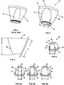
Fig. 1 is a perspective view of a prior art ophthalmic lens; -
Fig. 2 is a perspective view of a molded ophthalmic lens in accordance with one embodiment of the present invention; -
Fig. 3 is an illustration of the arc and chord of the curved main body portion of the ophthalmic lens ofFig. 2 ; -
Fig. 4A is a perspective view of an ophthalmic lens in accordance with the present invention having three mirrors with the first or Gonio mirror being shown; -
Fig. 4B is a perspective of the ophthalmic lens having three mirrors ofFig 4A with the second or periphery mirror being shown; -
Fig. 4C is a perspective view of the ophthalmic lens having three mirrors of 4A with the third or Arcades mirror being shown; -
Fig. 5 is a perspective view of a Gonio lens in accordance with the present invention; -
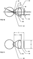
Fig. 6 is a perspective view of another embodiment of the ophthalmic lens of the present invention; -
Fig. 7 is a cross sectional view of the lens ofFig. 6 for a capsulotomy lens; -
Fig. 8 is a top view of the lens ofFig. 6 ; -
Fig. 9 is a cross sectional view of the lens ofFig. 6 for a iridotomy lens; and -
Figs. 10 and 11 are illustrations of a further embodiment of the ophthalmic lens of the present invention for an indirect lens that is used for observing the fundus of an eye. - An
ophthalmic lens 20 in accordance with one embodiment of the present invention, as shown inFig. 2 , has aneye contacting portion 22, agrip portion 24 and amain body portion 26 disposed between theeye contacting portion 22 and thegrip portion 24. Theeye contacting portion 22 of theophthalmic lens 20 is shaped to match a cornea of an eye. In a preferred embodiment, the eye contacting portion of the lens has a diameter of approximately 12.5 mm and a radius curvature of 7.75 mm. Thegrip portion 24 of theophthalmic lens 20 may have a generally cylindrical sidewall. In a preferred embodiment, thegrip portion 24 is textured so that a clinician can easily maintain his grip on thelens 20 during diagnosis or treatment. It is noted that, if desired, a larger grip surface may be added over thegrip portion 24. Thesurface 28 of thelens 20 opposite of theeye contacting portion 22 may be planar or curved for magnification. - The
eye contacting portion 22, themain body portion 26, and thegrip portion 24 of theophthalmic lens 20 are integrally formed of a molded, optical grade, acrylic resin. In a preferred embodiment, the acrylic resin is polymethylmethacrylate. The acrylic resin may have a specific gravity of 1.1-1.8. In a preferred embodiment, the specific gravity of the acrylic resin is 1.15-1.19 and the index of refraction of the acrylic resin is between 1.2 and 2.0. The molded ophthalmic lens may be injection molded and/or, compression molded. - In order to optimize the
ophthalmic lens 20 for molding, themain body portion 26 of theophthalmic lens 20 has asidewall 30 that is curved in two dimensions or curved about at least two axes. In a preferred embodiment, thecurved sidewall 30 is described by a sphere having a centerline that does not coincide with the center line of thelens 20. As shown inFigs. 2 and 3 , thecurved sidewall 30 has an arc 32 that extends from thegrip portion 24 at point A to theeye contacting portion 22 at point B. The length of thearc 22 is equal to or greater than 1.15 times the length X of the chord AB, i.e. the line segment extending from point A to point B. The shape of thesidewall 30 having an arc 32 that extends in a direction from thegrip portion 24 towards theeye contacting portion 22 allows any debris, bubbles and the like that tend to adhere to the surface of the mold during the molding process to collect away from the optical centerline of the lens so as to improve the optical quality of the molded ophthalmic lens. Moreover, the shape of the curved sidewall with the arc 32 also minimizes shrinkage during the molding process. - The
main body 26 of theophthalmic lens 20 is also molded with at least oneflat mirror surface 34. An additional benefit of the curved shape of themain body 26 is that the mirror surface(s) of theophthalmic lens 20 are larger than those of prior ophthalmic lenses of the same type. As such, the optical pathway used by the clinician during examination of the patient's eye is larger thereby reducing the need to manipulate or rotate theophthalmic lens 20 during the examination. This improves the examination and/or treatment procedure by allowing the clinician to view the interior of the eye more quickly. Moreover, the potential for abrasion of the patient's cornea from lens manipulation is reduced. For anophthalmic lens 20 having asingle mirror surface 34, the width W of themirror surface 34 may be at least 13 mm and preferably 13.7 mm or greater. The length, L, of theophthalmic lens 20 is at least 21 mm. In a preferred embodiment themirror surface 34 has an aluminum coating. -
Figures 4A-4C illustrates anophthalmic lens 40 having threemirror surfaces main body portion 26 of thelens 40. The length L of theophthalmic lens 40 is at least 27.5 mm. The first mirror surface 41 may be a Gonio mirror having a width that is at least 12 mm and preferably 12.8 mm or greater. Thesecond mirror surface 42 of theophthalmic lens 40 may be a periphery mirror having a width that is at least 15.6 mm and preferably 16.6 mm or greater. Thethird mirror surface 43 of thelens 40 may be an Arcades mirror having a width of at least 20 mm and preferably 21.4 mm or greater. In a preferred embodiment, each of the mirror surfaces 41, 42 and 43 has an aluminum coating. -
Fig. 5 illustrates aGonio lens 50 having four flat mirror surfaces 52 formed in the curved mainbody portion body 26 of theophthalmic lens 50. The length, L of thelens 40 is at least 17 mm. It is noted that because the flat mirror surfaces 52 of theGonio lens 50 are contiguous, aportion 51 of the arc 32 is projected as shown by the dotted line. As such, the arc 32 of the Gonio lens includesreal portions 53 on opposite sides of the projectedportion 51 wherein the length of the arc 32, i.e. the sum of the lengths of thereal portions 53 and the projectedportion 51, is at least 1.15 times the length of the chord of the arc 32. Each of the mirror surfaces 52 may have a width of at least 15.5 mm and preferably 15.9 mm or greater. In a preferred embodiment, each of the mirror surfaces 52 has an aluminum coating. - In another embodiment of the
ophthalmic lens 60 of the present invention, as depicted inFigs. 6-9 , thelens 60 includes anon-integral holder 62 that is made separately from theoptical lens 64. The optical orophthalmic lens 64 includes aneye contacting portion 66 and a magnifyingportion 68 that are integrally formed of polymethylmethacrylate having a specific gravity of 1.1 - 1.8 and preferably 1.15 - 1.19. The index of refraction of theophthalmic lens 64 is 1.2 - 2.0 and preferably 1.49. Theophthalmic lens 64 is injection molded and/or compression molded. Theophthalmic lens 64 has a clear aperture of at least 11.5 mm and preferably at least 12.5 mm. The clear aperture is the diameter of the mostanterior surface 70 of theophthalmic lens 64 into which a clinician looks. The most posterior surface of theophthalmic lens 64 is the surface 72 contacting the patient's eye. It is noted that in the embodiments ofFigs. 2-6 , the clear aperture of an ophthalmic lens having a mirror in the optical path is the width of the mirror. For a capsulotomy lens as shown inFig. 7 , the length of theophthalmic lens 64 is at least 9 mm and preferably 11.7 mm. For aniridotomy lens 74 as shown inFig. 9 , the length of theophthalmic lens 74 is at least 9 mm and preferably at 10 mm and the clear aperture is at least 11.5 mm and preferably 12.5 mm. Theiridotomy lens 74 is the same as thecapsulotomy lens 64 having aneye contacting portion 66 and a magnifyingportion 76 integrally formed of polymethylmethacrylate as described above except that the magnifyingportion 76 is de-centered. That is, the vertex of the magnifier of the iridotomy lens is off-center from the optical center line of theeye contacting portion 66. It is noted that a clear aperture of 11.5 mm and preferably 12.5 mm is larger than the clear aperture of prior capsulotomy and iridotomy lenses. This is extremely advantageous. For example, the larger aperture allows a physician to perform a peripheral capsulotomy which could not be performed with prior known capsulotomy lenses. - In a further embodiment of the present invention, an indirect
ophthalmic lens 80 for observing the fundus of an eye, as shown inFigs. 10 and 11 , includes aneye contacting lens 82 and anentry lens 83 supported by aholder 92. Each of theeye contacting lens 82 and theentry lens 83 are formed of molded polymethylmethacrylate having a specific gravity of 1.1 - 1.8 and preferably 1.15 - 1.19 and an index of refraction of 1.2 - 2.0 and preferably 1.49. Theeye contacting lens 82 and theentry lens 83 are injection molded and/or compression molded. Theeye contacting lens 82 has aposterior surface 84 having a radius of curvature that is substantially the same as the surface of a cornea. Theanterior surface 86 of the eye contacting lens has an aspheric shape such that the light rays entering the patient's eye through thecontact lens 82 are focused unto the fundus of the patient's eye. Theentry lens 83 is positioned anterior to theeye contacting lens 82 wherein the optical axes of theeye contacting lens 82 and theentry lens 83 are substantially coincident. Each of theanterior surface 88 and theposterior surface 90 of theentry lens 83 is aspheric as described below. Theholder 92 spaces theentry lens 83 from theeye contacting lens 82 so as to collect light rays from the fundus and to produce a realaerial image 94 wherein theimage 94 is in close proximity to theentry lens 83. In a preferred embodiment, the optical curvatures of thelenses aerial image 94 at a position that is less than 40 mm from theposterior surface 84 of thelens 82. In a preferred embodiment, the length, L, of theophthalmic lens 80 from theanterior surface 88 of the entry lens to theposterior surface 84 of the eye contacting lens is 34 mm or less. Further, the preferred diameter C, of theentry lens 83 is 35 mm or less. - The optical surfaces of the
lenses 
- For the
posterior surface 84 of thelens 82, the following values are preferred.


- For the
anterior surface 86 of thelens 82, the following values are preferred.

- For an
ophthalmic lens 80 having a 1.0 X magnification, the following values for theposterior surface 90 of the entry lens are preferred

- and the following values for the
anterior surface 88 of the entry lens are preferred.

- For an
ophthalmic lens 80 having a 0.7X magnification, the following values for theposterior surface 90 of the entry lens are preferred

- and the following values for the
anterior surface 88 of the entry lens are preferred.

- The ophthalmic lenses of the present invention are shaped to optimize the molding process of the lenses and improve the optical quality of the lenses. In particular, the clear aperture of each of the lenses is larger than prior known lenses of the same type. Moreover, because the ophthalmic lenses of the present invention are molded as opposed to machined, the ophthalmic lenses of the present invention can be massed produced in volume at low cost. As such, the ophthalmic lenses of the present invention are particularly suitable for single use applications of the lenses. Because the ophthalmic lenses of the present invention are single use ophthalmic lenses that may be used once and then disposed of, disease transmission via the lenses is substantially minimized.
- Many modifications and variations of the present invention are possible in light of the above teachings. Thus, it is to be understood that, within the scope of the appended claims, the invention may be practiced otherwise than as described hereinabove.
Claims (20)
- An ophthalmic lens comprising: a grip portion, an eye contacting portion and a main body portion disposed between the grip portion and the eye contacting portion wherein the grip portion, the eye contacting portion and the main body portion are integrally formed of a polymethylmethacrylate having a specific gravity of 1.1-1.8, the eye contacting portion is shaped to contact the cornea of the eye, and the main body portion has a curved sidewall with an arc extending in a direction from the grip portion towards the eye contacting portion, the arc having a length that is at least 1.15 times the length of a chord of the arc and the main body portion having at least one mirror surface for reflecting light to and from the eye contacting portion.
- An ophthalmic lens comprising: a grip portion, an eye contacting portion, and a main body portion disposed between the grip portion and the eye contacting portion wherein the grip portion, the eye contacting portion and the main body portion are integrally formed of molded polymethylmethacrylate, the eye contacting portion is shaped to contact the cornea of the eye, and the main body portion has a curved sidewall with an arc extending in a direction from the grip portion towards the eye contacting portion, the arc having a length that is at least 1.15 times the length of the chord of the arc.
- An ophthalmic lens as recited in claim 1 wherein the specific gravity is 1.15-1.19.
- An ophthalmic lens as recited in claim 1 further including an aluminum coating on the mirror surface.
- An ophthalmic lens as recited in claim 2 wherein the polymethylmethacrylate has a specific gravity of 1.1-1.8 or of 1.15-1:19.
- An ophthalmic lens as recited in claim 1 wherein the acrylic resin is injection molded and/or compression molded.
- An ophthalmic lens as recited in claim 1 or 2 wherein an axis of rotation of the curved sidewall does not coincide with the centerline of the lens.
- An ophthalmic lens as recited in claim 1 or 2 wherein the arc extends from the grip portion to the eye contacting portion.
- An ophthalmic lens as recited in claim 1 or 2 having an index of refraction between 1.2 and 2.0.
- An ophthalmic lens as recited in claim 1 or 2 having a Gonio mirror with a width that is at least 12 mm; a periphery mirror with a width that is at least 15.6 mm and an Arcades mirror with a width that is at least 20 mm,
wherein the ophthalmic lens preferably has a length that is at least 27.5 mm. - An ophthalmic lens as recited in claim 1 or 2 having a Gonio mirror with a width that is at least 12.8 mm; a periphery mirror with a width that is at least 16.6 mm and an Arcades mirror having a width that is at least 21.4 mm.
- An ophthalmic lens as recited in claim 1 or 2 wherein the lens is a Gonio lens having four mirrors each having a width that is at least 15.5 mm,
wherein the ophthalmic lens preferably has a length of at least 17 mm. - An ophthalmic lens as recited in claim 1 or 2 wherein the lens is a Gonio lens having four mirrors each having a width that is at least 15.9 mm.
- An ophthalmic lens as recited in claim 1 or 2 having a single mirror with a width that is at least 13.5 mm,
wherein the ophthalmic lens preferably has a length of at least 21 mm. - An ophthalmic lens as recited in claim 1 or 2 having a single mirror with a width that is at least 13.7 mm.
- An ophthalmic lens comprising: a grip portion, an eye contacting portion and a main body portion disposed between the grip portion and the eye contacting portion wherein the grip portion, the eye contacting portion and the main body portion are integrally formed of a polymethylmethacrylate having a specific gravity of 1.1-1.8, the eye contacting portion is shaped to contact the cornea of the eye, and the main body portion has a curved sidewall that is described by a sphere having a centerline that does not coincide with the centerline of the lens and at least one flat surface for a mirror for reflecting light to and from the eye contacting portion.
- An ophthalmic lens as recited in claim 16 wherein the specific gravity is 1.15-1.19.
- An ophthalmic lens as recited in claim 16 wherein the polymethylmethacrylate is injection molded or compression molded.
- An ophthalmic lens as recited in claim 16 wherein the curved sidewall has an arc extending from the grip portion to the eye contacting portion wherein the length of the arc is at least 1.15 times the length of a chord of the arc.
- An ophthalmic lens as recited in claim 16 having an index of refraction between 1.2 and 2.0.
Priority Applications (1)
| Application Number | Priority Date | Filing Date | Title |
|---|---|---|---|
| EP17150449.1A EP3187919A3 (en) | 2010-11-08 | 2011-10-13 | Molded ophthalmic lens |
Applications Claiming Priority (2)
| Application Number | Priority Date | Filing Date | Title |
|---|---|---|---|
| US12/941,164 US8303116B2 (en) | 2010-11-08 | 2010-11-08 | Molded ophthalmic lens |
| PCT/US2011/056117 WO2012064458A1 (en) | 2010-11-08 | 2011-10-13 | Molded ophthalmic lens |
Related Child Applications (2)
| Application Number | Title | Priority Date | Filing Date |
|---|---|---|---|
| EP17150449.1A Division EP3187919A3 (en) | 2010-11-08 | 2011-10-13 | Molded ophthalmic lens |
| EP17150449.1A Division-Into EP3187919A3 (en) | 2010-11-08 | 2011-10-13 | Molded ophthalmic lens |
Publications (3)
| Publication Number | Publication Date |
|---|---|
| EP2638426A1 EP2638426A1 (en) | 2013-09-18 |
| EP2638426A4 EP2638426A4 (en) | 2016-05-25 |
| EP2638426B1 true EP2638426B1 (en) | 2018-04-25 |
Family
ID=46019348
Family Applications (2)
| Application Number | Title | Priority Date | Filing Date |
|---|---|---|---|
| EP17150449.1A Pending EP3187919A3 (en) | 2010-11-08 | 2011-10-13 | Molded ophthalmic lens |
| EP11839682.9A Active EP2638426B1 (en) | 2010-11-08 | 2011-10-13 | Molded ophthalmic lens |
Family Applications Before (1)
| Application Number | Title | Priority Date | Filing Date |
|---|---|---|---|
| EP17150449.1A Pending EP3187919A3 (en) | 2010-11-08 | 2011-10-13 | Molded ophthalmic lens |
Country Status (4)
| Country | Link |
|---|---|
| US (1) | US8303116B2 (en) |
| EP (2) | EP3187919A3 (en) |
| JP (3) | JP6126533B2 (en) |
| WO (1) | WO2012064458A1 (en) |
Families Citing this family (11)
| Publication number | Priority date | Publication date | Assignee | Title |
|---|---|---|---|---|
| US8801185B2 (en) | 2011-03-25 | 2014-08-12 | Eos Holdings, Llc | Ophthalmic inspection lens |
| WO2015001200A1 (en) * | 2013-07-05 | 2015-01-08 | Phakos | Indirect ophthalmoscopy lens device used for observing the eye |
| WO2015168695A1 (en) * | 2014-05-02 | 2015-11-05 | Ocular Instruments, Inc. | Unreversed prism gonioscopy lens assembly |
| US10663760B2 (en) | 2014-09-10 | 2020-05-26 | Katena Products, Inc. | Molded ophthalmic contact lens |
| US10353118B2 (en) * | 2014-09-10 | 2019-07-16 | Katena Products, Inc. | Molded ophthalmic lens with integral ring portion for examination or treatment of an eye |
| US9636012B2 (en) | 2014-09-26 | 2017-05-02 | Volk Optical Inc. | Ophthalmic lens assemblies and methods of assembly and use |
| USD816262S1 (en) * | 2015-05-15 | 2018-04-24 | Philips Lighting Holding B.V. | LED candle lens |
| USD777928S1 (en) * | 2015-10-13 | 2017-01-31 | Katena Products, Inc. | Ophthalmic lens |
| USD775357S1 (en) * | 2015-10-13 | 2016-12-27 | Katena Products, Inc. | Ophthalmic lens |
| EP3417341B1 (en) * | 2016-02-18 | 2020-11-25 | Katena Products, Inc. | Molded ophthalmic lens |
| US11890051B2 (en) | 2017-02-06 | 2024-02-06 | Sensor, LLC | Apparatus with filter to treat macular degeneration and method of treating macular degeneration |
Family Cites Families (17)
| Publication number | Priority date | Publication date | Assignee | Title |
|---|---|---|---|---|
| US3589800A (en) * | 1969-06-05 | 1971-06-29 | Hernando Cardona | Gonioscopic lens |
| DE2246182A1 (en) * | 1972-09-20 | 1974-03-28 | Rudolf Dr Dr Weinzierl | VIEWING OPTICS |
| US4134647A (en) * | 1977-03-22 | 1979-01-16 | Ramos Caldera Arturo J | Contact lens for examining the interior of the eye |
| US4728183A (en) * | 1986-10-01 | 1988-03-01 | Ocular Instruments, Inc. | Ophthalmic lens for observing the fundus of the eye |
| US5007729A (en) * | 1989-10-27 | 1991-04-16 | Ocular Instruments, Inc. | Wide angle ophthalmic lens |
| JP2554219Y2 (en) * | 1991-08-30 | 1997-11-17 | 京都コンタクトレンズ株式会社 | Contact lenses for intraocular vitreous surgery |
| US5537164A (en) | 1994-12-20 | 1996-07-16 | Smith; Alan D. | Retroilluminating indirect gonioprism |
| EP1017308B1 (en) * | 1996-10-24 | 2003-06-04 | Volk Optical, Inc. | Ophthalmoscopic viewing system |
| US5953097A (en) * | 1997-06-24 | 1999-09-14 | Neuroptics, Inc. | Contact lens for use with ophthalmic monitoring systems |
| US6797004B1 (en) * | 2000-03-02 | 2004-09-28 | Advanced Medical Optics, Inc. | Holders for intraocular lenses |
| US6893398B2 (en) * | 2001-04-19 | 2005-05-17 | Odc Ophthalmic Development Company Ag | Device for measuring intraocular pressure, in particular a tonometer |
| US6851808B2 (en) * | 2001-11-16 | 2005-02-08 | Gregory L. Heacock | Disposable Ophthalmic lens |
| US6860601B2 (en) * | 2002-02-06 | 2005-03-01 | John H. Shadduck | Adaptive optic lens system and method of use |
| US6767098B2 (en) * | 2002-08-29 | 2004-07-27 | Ocular Instruments, Inc. | Ophthalmoscopic prism |
| US6976758B2 (en) * | 2003-04-04 | 2005-12-20 | Ocular Instruments, Inc. | Gonioscopy lens |
| US6942343B2 (en) * | 2003-04-07 | 2005-09-13 | Arkadiy Farberov | Optical device for intraocular observation |
| US7789512B2 (en) * | 2007-08-23 | 2010-09-07 | Volk Donald A | Real image forming eye examination lens utilizing two reflecting surfaces |
-
2010
- 2010-11-08 US US12/941,164 patent/US8303116B2/en active Active
-
2011
- 2011-10-13 WO PCT/US2011/056117 patent/WO2012064458A1/en active Application Filing
- 2011-10-13 EP EP17150449.1A patent/EP3187919A3/en active Pending
- 2011-10-13 JP JP2013538735A patent/JP6126533B2/en active Active
- 2011-10-13 EP EP11839682.9A patent/EP2638426B1/en active Active
-
2016
- 2016-10-28 JP JP2016211423A patent/JP6470727B2/en active Active
-
2019
- 2019-01-18 JP JP2019006764A patent/JP2019069265A/en active Pending
Non-Patent Citations (1)
| Title |
|---|
| None * |
Also Published As
| Publication number | Publication date |
|---|---|
| EP2638426A4 (en) | 2016-05-25 |
| EP3187919A3 (en) | 2017-10-25 |
| JP2013546020A (en) | 2013-12-26 |
| EP2638426A1 (en) | 2013-09-18 |
| US8303116B2 (en) | 2012-11-06 |
| US20120113392A1 (en) | 2012-05-10 |
| JP6470727B2 (en) | 2019-02-13 |
| EP3187919A2 (en) | 2017-07-05 |
| JP2019069265A (en) | 2019-05-09 |
| JP6126533B2 (en) | 2017-05-10 |
| JP2017047243A (en) | 2017-03-09 |
| WO2012064458A1 (en) | 2012-05-18 |
Similar Documents
| Publication | Publication Date | Title |
|---|---|---|
| EP2638426B1 (en) | Molded ophthalmic lens | |
| US5430506A (en) | Indirect ophthalmoscopy lens for use with slit lamp biomicroscope | |
| EP0425310B1 (en) | Wide angle ophthalmic lens | |
| CA2177193C (en) | Indirect ophthalmoscopy contact lens device with compound contact lens element | |
| US5784147A (en) | Indirect ophthalmoscopy lens system | |
| US20100091244A1 (en) | Real image forming eye examination lens utilizing two reflecting surfaces with non-mirrored central viewing area | |
| US20090185135A1 (en) | Real image forming eye examination lens utilizing two reflecting surfaces providing upright image | |
| US7789512B2 (en) | Real image forming eye examination lens utilizing two reflecting surfaces | |
| US5623323A (en) | Extra wide field ophthalmic lens | |
| WO1993019395A1 (en) | High magnification ophthalmic lens | |
| JPH08508653A (en) | Indirect ophthalmoscope lens for use in slit lamp biomicroscopes | |
| US20160161762A1 (en) | Molded Ophthalmic Lens | |
| JP6700256B2 (en) | Molded ophthalmic lens | |
| JP7049257B2 (en) | Molded eye lens | |
| JP2021186471A (en) | Manufacturing method of objective lens system for wide-angle fundus imaging apparatus | |
| CN113835213A (en) | Lightweight eyepiece with large exit pupil diameter |
Legal Events
| Date | Code | Title | Description |
|---|---|---|---|
| PUAI | Public reference made under article 153(3) epc to a published international application that has entered the european phase |
Free format text: ORIGINAL CODE: 0009012 |
|
| 17P | Request for examination filed |
Effective date: 20130508 |
|
| AK | Designated contracting states |
Kind code of ref document: A1 Designated state(s): AL AT BE BG CH CY CZ DE DK EE ES FI FR GB GR HR HU IE IS IT LI LT LU LV MC MK MT NL NO PL PT RO RS SE SI SK SM TR |
|
| DAX | Request for extension of the european patent (deleted) | ||
| RAP1 | Party data changed (applicant data changed or rights of an application transferred) |
Owner name: SENSOR INTERNATIONAL, LLC |
|
| RIN1 | Information on inventor provided before grant (corrected) |
Inventor name: SENSOR INTERNATIONAL, LLC |
|
| RA4 | Supplementary search report drawn up and despatched (corrected) |
Effective date: 20160421 |
|
| RIC1 | Information provided on ipc code assigned before grant |
Ipc: G02C 7/04 20060101AFI20160415BHEP Ipc: A61B 3/117 20060101ALI20160415BHEP |
|
| RAP1 | Party data changed (applicant data changed or rights of an application transferred) |
Owner name: KATENA PRODUCTS, INC. |
|
| RIN1 | Information on inventor provided before grant (corrected) |
Inventor name: KATENA PRODUCTS, INC. |
|
| RIN1 | Information on inventor provided before grant (corrected) |
Inventor name: HEACOCK, GREGORY LEE |
|
| RIC1 | Information provided on ipc code assigned before grant |
Ipc: A61B 3/117 20060101ALI20170405BHEP Ipc: G02C 7/04 20060101AFI20170405BHEP |
|
| GRAP | Despatch of communication of intention to grant a patent |
Free format text: ORIGINAL CODE: EPIDOSNIGR1 |
|
| INTG | Intention to grant announced |
Effective date: 20170515 |
|
| RIN1 | Information on inventor provided before grant (corrected) |
Inventor name: HEACOCK, GREGORY LEE |
|
| GRAJ | Information related to disapproval of communication of intention to grant by the applicant or resumption of examination proceedings by the epo deleted |
Free format text: ORIGINAL CODE: EPIDOSDIGR1 |
|
| INTC | Intention to grant announced (deleted) | ||
| GRAP | Despatch of communication of intention to grant a patent |
Free format text: ORIGINAL CODE: EPIDOSNIGR1 |
|
| INTG | Intention to grant announced |
Effective date: 20171110 |
|
| GRAA | (expected) grant |
Free format text: ORIGINAL CODE: 0009210 |
|
| GRAS | Grant fee paid |
Free format text: ORIGINAL CODE: EPIDOSNIGR3 |
|
| AK | Designated contracting states |
Kind code of ref document: B1 Designated state(s): AL AT BE BG CH CY CZ DE DK EE ES FI FR GB GR HR HU IE IS IT LI LT LU LV MC MK MT NL NO PL PT RO RS SE SI SK SM TR |
|
| REG | Reference to a national code |
Ref country code: GB Ref legal event code: FG4D |
|
| REG | Reference to a national code |
Ref country code: CH Ref legal event code: EP |
|
| REG | Reference to a national code |
Ref country code: AT Ref legal event code: REF Ref document number: 993524 Country of ref document: AT Kind code of ref document: T Effective date: 20180515 |
|
| REG | Reference to a national code |
Ref country code: IE Ref legal event code: FG4D |
|
| REG | Reference to a national code |
Ref country code: DE Ref legal event code: R096 Ref document number: 602011047912 Country of ref document: DE |
|
| REG | Reference to a national code |
Ref country code: CH Ref legal event code: NV Representative=s name: TR-IP CONSULTING LLC, CH Ref country code: CH Ref legal event code: PCOW Free format text: NEW ADDRESS: 4 STEWART COURT, DENVILLE, NJ 07834 (US) |
|
| RAP2 | Party data changed (patent owner data changed or rights of a patent transferred) |
Owner name: KATENA PRODUCTS, INC. |
|
| REG | Reference to a national code |
Ref country code: NL Ref legal event code: MP Effective date: 20180425 |
|
| REG | Reference to a national code |
Ref country code: LT Ref legal event code: MG4D |
|
| PG25 | Lapsed in a contracting state [announced via postgrant information from national office to epo] |
Ref country code: NL Free format text: LAPSE BECAUSE OF FAILURE TO SUBMIT A TRANSLATION OF THE DESCRIPTION OR TO PAY THE FEE WITHIN THE PRESCRIBED TIME-LIMIT Effective date: 20180425 |
|
| REG | Reference to a national code |
Ref country code: DE Ref legal event code: R082 Ref document number: 602011047912 Country of ref document: DE Representative=s name: ZWICKER SCHNAPPAUF & PARTNER PATENTANWAELTE PA, DE Ref country code: DE Ref legal event code: R082 Ref document number: 602011047912 Country of ref document: DE Representative=s name: ZSP PATENTANWAELTE PARTG MBB, DE Ref country code: DE Ref legal event code: R081 Ref document number: 602011047912 Country of ref document: DE Owner name: KATENA PRODUCTS, INC., DENVILLE, US Free format text: FORMER OWNER: KATENA PRODUCTS, INC., MAPLE VALLEY, WASH., US |
|
| REG | Reference to a national code |
Ref country code: FR Ref legal event code: PLFP Year of fee payment: 8 |
|
| PG25 | Lapsed in a contracting state [announced via postgrant information from national office to epo] |
Ref country code: BG Free format text: LAPSE BECAUSE OF FAILURE TO SUBMIT A TRANSLATION OF THE DESCRIPTION OR TO PAY THE FEE WITHIN THE PRESCRIBED TIME-LIMIT Effective date: 20180725 Ref country code: NO Free format text: LAPSE BECAUSE OF FAILURE TO SUBMIT A TRANSLATION OF THE DESCRIPTION OR TO PAY THE FEE WITHIN THE PRESCRIBED TIME-LIMIT Effective date: 20180725 Ref country code: FI Free format text: LAPSE BECAUSE OF FAILURE TO SUBMIT A TRANSLATION OF THE DESCRIPTION OR TO PAY THE FEE WITHIN THE PRESCRIBED TIME-LIMIT Effective date: 20180425 Ref country code: PL Free format text: LAPSE BECAUSE OF FAILURE TO SUBMIT A TRANSLATION OF THE DESCRIPTION OR TO PAY THE FEE WITHIN THE PRESCRIBED TIME-LIMIT Effective date: 20180425 Ref country code: SE Free format text: LAPSE BECAUSE OF FAILURE TO SUBMIT A TRANSLATION OF THE DESCRIPTION OR TO PAY THE FEE WITHIN THE PRESCRIBED TIME-LIMIT Effective date: 20180425 Ref country code: ES Free format text: LAPSE BECAUSE OF FAILURE TO SUBMIT A TRANSLATION OF THE DESCRIPTION OR TO PAY THE FEE WITHIN THE PRESCRIBED TIME-LIMIT Effective date: 20180425 Ref country code: LT Free format text: LAPSE BECAUSE OF FAILURE TO SUBMIT A TRANSLATION OF THE DESCRIPTION OR TO PAY THE FEE WITHIN THE PRESCRIBED TIME-LIMIT Effective date: 20180425 |
|
| PG25 | Lapsed in a contracting state [announced via postgrant information from national office to epo] |
Ref country code: LV Free format text: LAPSE BECAUSE OF FAILURE TO SUBMIT A TRANSLATION OF THE DESCRIPTION OR TO PAY THE FEE WITHIN THE PRESCRIBED TIME-LIMIT Effective date: 20180425 Ref country code: HR Free format text: LAPSE BECAUSE OF FAILURE TO SUBMIT A TRANSLATION OF THE DESCRIPTION OR TO PAY THE FEE WITHIN THE PRESCRIBED TIME-LIMIT Effective date: 20180425 Ref country code: GR Free format text: LAPSE BECAUSE OF FAILURE TO SUBMIT A TRANSLATION OF THE DESCRIPTION OR TO PAY THE FEE WITHIN THE PRESCRIBED TIME-LIMIT Effective date: 20180726 Ref country code: RS Free format text: LAPSE BECAUSE OF FAILURE TO SUBMIT A TRANSLATION OF THE DESCRIPTION OR TO PAY THE FEE WITHIN THE PRESCRIBED TIME-LIMIT Effective date: 20180425 |
|
| REG | Reference to a national code |
Ref country code: AT Ref legal event code: MK05 Ref document number: 993524 Country of ref document: AT Kind code of ref document: T Effective date: 20180425 |
|
| PG25 | Lapsed in a contracting state [announced via postgrant information from national office to epo] |
Ref country code: PT Free format text: LAPSE BECAUSE OF FAILURE TO SUBMIT A TRANSLATION OF THE DESCRIPTION OR TO PAY THE FEE WITHIN THE PRESCRIBED TIME-LIMIT Effective date: 20180827 |
|
| REG | Reference to a national code |
Ref country code: DE Ref legal event code: R097 Ref document number: 602011047912 Country of ref document: DE |
|
| PG25 | Lapsed in a contracting state [announced via postgrant information from national office to epo] |
Ref country code: DK Free format text: LAPSE BECAUSE OF FAILURE TO SUBMIT A TRANSLATION OF THE DESCRIPTION OR TO PAY THE FEE WITHIN THE PRESCRIBED TIME-LIMIT Effective date: 20180425 Ref country code: RO Free format text: LAPSE BECAUSE OF FAILURE TO SUBMIT A TRANSLATION OF THE DESCRIPTION OR TO PAY THE FEE WITHIN THE PRESCRIBED TIME-LIMIT Effective date: 20180425 Ref country code: AT Free format text: LAPSE BECAUSE OF FAILURE TO SUBMIT A TRANSLATION OF THE DESCRIPTION OR TO PAY THE FEE WITHIN THE PRESCRIBED TIME-LIMIT Effective date: 20180425 Ref country code: EE Free format text: LAPSE BECAUSE OF FAILURE TO SUBMIT A TRANSLATION OF THE DESCRIPTION OR TO PAY THE FEE WITHIN THE PRESCRIBED TIME-LIMIT Effective date: 20180425 Ref country code: CZ Free format text: LAPSE BECAUSE OF FAILURE TO SUBMIT A TRANSLATION OF THE DESCRIPTION OR TO PAY THE FEE WITHIN THE PRESCRIBED TIME-LIMIT Effective date: 20180425 Ref country code: SK Free format text: LAPSE BECAUSE OF FAILURE TO SUBMIT A TRANSLATION OF THE DESCRIPTION OR TO PAY THE FEE WITHIN THE PRESCRIBED TIME-LIMIT Effective date: 20180425 |
|
| PG25 | Lapsed in a contracting state [announced via postgrant information from national office to epo] |
Ref country code: SM Free format text: LAPSE BECAUSE OF FAILURE TO SUBMIT A TRANSLATION OF THE DESCRIPTION OR TO PAY THE FEE WITHIN THE PRESCRIBED TIME-LIMIT Effective date: 20180425 Ref country code: IT Free format text: LAPSE BECAUSE OF FAILURE TO SUBMIT A TRANSLATION OF THE DESCRIPTION OR TO PAY THE FEE WITHIN THE PRESCRIBED TIME-LIMIT Effective date: 20180425 |
|
| PLBE | No opposition filed within time limit |
Free format text: ORIGINAL CODE: 0009261 |
|
| STAA | Information on the status of an ep patent application or granted ep patent |
Free format text: STATUS: NO OPPOSITION FILED WITHIN TIME LIMIT |
|
| 26N | No opposition filed |
Effective date: 20190128 |
|
| PG25 | Lapsed in a contracting state [announced via postgrant information from national office to epo] |
Ref country code: SI Free format text: LAPSE BECAUSE OF FAILURE TO SUBMIT A TRANSLATION OF THE DESCRIPTION OR TO PAY THE FEE WITHIN THE PRESCRIBED TIME-LIMIT Effective date: 20180425 |
|
| REG | Reference to a national code |
Ref country code: BE Ref legal event code: MM Effective date: 20181031 |
|
| PG25 | Lapsed in a contracting state [announced via postgrant information from national office to epo] |
Ref country code: LU Free format text: LAPSE BECAUSE OF NON-PAYMENT OF DUE FEES Effective date: 20181013 Ref country code: MC Free format text: LAPSE BECAUSE OF FAILURE TO SUBMIT A TRANSLATION OF THE DESCRIPTION OR TO PAY THE FEE WITHIN THE PRESCRIBED TIME-LIMIT Effective date: 20180425 |
|
| REG | Reference to a national code |
Ref country code: IE Ref legal event code: MM4A |
|
| PG25 | Lapsed in a contracting state [announced via postgrant information from national office to epo] |
Ref country code: BE Free format text: LAPSE BECAUSE OF NON-PAYMENT OF DUE FEES Effective date: 20181031 |
|
| PG25 | Lapsed in a contracting state [announced via postgrant information from national office to epo] |
Ref country code: IE Free format text: LAPSE BECAUSE OF NON-PAYMENT OF DUE FEES Effective date: 20181013 |
|
| REG | Reference to a national code |
Ref country code: DE Ref legal event code: R082 Ref document number: 602011047912 Country of ref document: DE Representative=s name: ZWICKER SCHNAPPAUF & PARTNER PATENTANWAELTE PA, DE |
|
| PG25 | Lapsed in a contracting state [announced via postgrant information from national office to epo] |
Ref country code: AL Free format text: LAPSE BECAUSE OF FAILURE TO SUBMIT A TRANSLATION OF THE DESCRIPTION OR TO PAY THE FEE WITHIN THE PRESCRIBED TIME-LIMIT Effective date: 20180425 |
|
| PG25 | Lapsed in a contracting state [announced via postgrant information from national office to epo] |
Ref country code: MT Free format text: LAPSE BECAUSE OF NON-PAYMENT OF DUE FEES Effective date: 20181013 |
|
| REG | Reference to a national code |
Ref country code: CH Ref legal event code: PCAR Free format text: NEW ADDRESS: ROUTE DU COUTSET 18, 1485 NUVILLY (CH) |
|
| PG25 | Lapsed in a contracting state [announced via postgrant information from national office to epo] |
Ref country code: TR Free format text: LAPSE BECAUSE OF FAILURE TO SUBMIT A TRANSLATION OF THE DESCRIPTION OR TO PAY THE FEE WITHIN THE PRESCRIBED TIME-LIMIT Effective date: 20180425 |
|
| PG25 | Lapsed in a contracting state [announced via postgrant information from national office to epo] |
Ref country code: HU Free format text: LAPSE BECAUSE OF FAILURE TO SUBMIT A TRANSLATION OF THE DESCRIPTION OR TO PAY THE FEE WITHIN THE PRESCRIBED TIME-LIMIT; INVALID AB INITIO Effective date: 20111013 Ref country code: CY Free format text: LAPSE BECAUSE OF FAILURE TO SUBMIT A TRANSLATION OF THE DESCRIPTION OR TO PAY THE FEE WITHIN THE PRESCRIBED TIME-LIMIT Effective date: 20180425 Ref country code: MK Free format text: LAPSE BECAUSE OF NON-PAYMENT OF DUE FEES Effective date: 20180425 |
|
| PG25 | Lapsed in a contracting state [announced via postgrant information from national office to epo] |
Ref country code: IS Free format text: LAPSE BECAUSE OF FAILURE TO SUBMIT A TRANSLATION OF THE DESCRIPTION OR TO PAY THE FEE WITHIN THE PRESCRIBED TIME-LIMIT Effective date: 20180825 |
|
| P01 | Opt-out of the competence of the unified patent court (upc) registered |
Effective date: 20230516 |
|
| P02 | Opt-out of the competence of the unified patent court (upc) changed |
Effective date: 20230612 |
|
| PGFP | Annual fee paid to national office [announced via postgrant information from national office to epo] |
Ref country code: GB Payment date: 20231027 Year of fee payment: 13 |
|
| PGFP | Annual fee paid to national office [announced via postgrant information from national office to epo] |
Ref country code: FR Payment date: 20231025 Year of fee payment: 13 Ref country code: DE Payment date: 20231027 Year of fee payment: 13 Ref country code: CH Payment date: 20231102 Year of fee payment: 13 |