EP2637943B1 - Resealable opening device and package comprising such an opening device - Google Patents
Resealable opening device and package comprising such an opening device Download PDFInfo
- Publication number
- EP2637943B1 EP2637943B1 EP11779458.6A EP11779458A EP2637943B1 EP 2637943 B1 EP2637943 B1 EP 2637943B1 EP 11779458 A EP11779458 A EP 11779458A EP 2637943 B1 EP2637943 B1 EP 2637943B1
- Authority
- EP
- European Patent Office
- Prior art keywords
- opening
- package
- opening device
- folding
- folding axis
- Prior art date
- Legal status (The legal status is an assumption and is not a legal conclusion. Google has not performed a legal analysis and makes no representation as to the accuracy of the status listed.)
- Active
Links
Images






Classifications
-
- B—PERFORMING OPERATIONS; TRANSPORTING
- B65—CONVEYING; PACKING; STORING; HANDLING THIN OR FILAMENTARY MATERIAL
- B65D—CONTAINERS FOR STORAGE OR TRANSPORT OF ARTICLES OR MATERIALS, e.g. BAGS, BARRELS, BOTTLES, BOXES, CANS, CARTONS, CRATES, DRUMS, JARS, TANKS, HOPPERS, FORWARDING CONTAINERS; ACCESSORIES, CLOSURES, OR FITTINGS THEREFOR; PACKAGING ELEMENTS; PACKAGES
- B65D33/00—Details of, or accessories for, sacks or bags
- B65D33/16—End- or aperture-closing arrangements or devices
-
- B—PERFORMING OPERATIONS; TRANSPORTING
- B31—MAKING ARTICLES OF PAPER, CARDBOARD OR MATERIAL WORKED IN A MANNER ANALOGOUS TO PAPER; WORKING PAPER, CARDBOARD OR MATERIAL WORKED IN A MANNER ANALOGOUS TO PAPER
- B31B—MAKING CONTAINERS OF PAPER, CARDBOARD OR MATERIAL WORKED IN A MANNER ANALOGOUS TO PAPER
- B31B50/00—Making rigid or semi-rigid containers, e.g. boxes or cartons
-
- B—PERFORMING OPERATIONS; TRANSPORTING
- B31—MAKING ARTICLES OF PAPER, CARDBOARD OR MATERIAL WORKED IN A MANNER ANALOGOUS TO PAPER; WORKING PAPER, CARDBOARD OR MATERIAL WORKED IN A MANNER ANALOGOUS TO PAPER
- B31B—MAKING CONTAINERS OF PAPER, CARDBOARD OR MATERIAL WORKED IN A MANNER ANALOGOUS TO PAPER
- B31B70/00—Making flexible containers, e.g. envelopes or bags
- B31B70/60—Uniting opposed surfaces or edges; Taping
- B31B70/64—Uniting opposed surfaces or edges; Taping by applying heat or pressure
-
- B—PERFORMING OPERATIONS; TRANSPORTING
- B65—CONVEYING; PACKING; STORING; HANDLING THIN OR FILAMENTARY MATERIAL
- B65D—CONTAINERS FOR STORAGE OR TRANSPORT OF ARTICLES OR MATERIALS, e.g. BAGS, BARRELS, BOTTLES, BOXES, CANS, CARTONS, CRATES, DRUMS, JARS, TANKS, HOPPERS, FORWARDING CONTAINERS; ACCESSORIES, CLOSURES, OR FITTINGS THEREFOR; PACKAGING ELEMENTS; PACKAGES
- B65D33/00—Details of, or accessories for, sacks or bags
- B65D33/16—End- or aperture-closing arrangements or devices
- B65D33/1658—Elements for flattening or folding the mouth portion
- B65D33/1675—Hinged clips
-
- B—PERFORMING OPERATIONS; TRANSPORTING
- B65—CONVEYING; PACKING; STORING; HANDLING THIN OR FILAMENTARY MATERIAL
- B65D—CONTAINERS FOR STORAGE OR TRANSPORT OF ARTICLES OR MATERIALS, e.g. BAGS, BARRELS, BOTTLES, BOXES, CANS, CARTONS, CRATES, DRUMS, JARS, TANKS, HOPPERS, FORWARDING CONTAINERS; ACCESSORIES, CLOSURES, OR FITTINGS THEREFOR; PACKAGING ELEMENTS; PACKAGES
- B65D33/00—Details of, or accessories for, sacks or bags
- B65D33/16—End- or aperture-closing arrangements or devices
- B65D33/1683—A pair of interconnecting rigid strips made of plastic material, e.g. one or both being provided with a handle or suspension means
-
- B—PERFORMING OPERATIONS; TRANSPORTING
- B65—CONVEYING; PACKING; STORING; HANDLING THIN OR FILAMENTARY MATERIAL
- B65D—CONTAINERS FOR STORAGE OR TRANSPORT OF ARTICLES OR MATERIALS, e.g. BAGS, BARRELS, BOTTLES, BOXES, CANS, CARTONS, CRATES, DRUMS, JARS, TANKS, HOPPERS, FORWARDING CONTAINERS; ACCESSORIES, CLOSURES, OR FITTINGS THEREFOR; PACKAGING ELEMENTS; PACKAGES
- B65D33/00—Details of, or accessories for, sacks or bags
- B65D33/16—End- or aperture-closing arrangements or devices
- B65D33/1691—End- or aperture-closing arrangements or devices using adhesive applied to attached closure elements
-
- B—PERFORMING OPERATIONS; TRANSPORTING
- B65—CONVEYING; PACKING; STORING; HANDLING THIN OR FILAMENTARY MATERIAL
- B65D—CONTAINERS FOR STORAGE OR TRANSPORT OF ARTICLES OR MATERIALS, e.g. BAGS, BARRELS, BOTTLES, BOXES, CANS, CARTONS, CRATES, DRUMS, JARS, TANKS, HOPPERS, FORWARDING CONTAINERS; ACCESSORIES, CLOSURES, OR FITTINGS THEREFOR; PACKAGING ELEMENTS; PACKAGES
- B65D33/00—Details of, or accessories for, sacks or bags
- B65D33/16—End- or aperture-closing arrangements or devices
- B65D33/25—Riveting; Dovetailing; Screwing; using press buttons or slide fasteners
-
- B—PERFORMING OPERATIONS; TRANSPORTING
- B65—CONVEYING; PACKING; STORING; HANDLING THIN OR FILAMENTARY MATERIAL
- B65D—CONTAINERS FOR STORAGE OR TRANSPORT OF ARTICLES OR MATERIALS, e.g. BAGS, BARRELS, BOTTLES, BOXES, CANS, CARTONS, CRATES, DRUMS, JARS, TANKS, HOPPERS, FORWARDING CONTAINERS; ACCESSORIES, CLOSURES, OR FITTINGS THEREFOR; PACKAGING ELEMENTS; PACKAGES
- B65D75/00—Packages comprising articles or materials partially or wholly enclosed in strips, sheets, blanks, tubes or webs of flexible sheet material, e.g. in folded wrappers
- B65D75/008—Standing pouches, i.e. "Standbeutel"
-
- B—PERFORMING OPERATIONS; TRANSPORTING
- B65—CONVEYING; PACKING; STORING; HANDLING THIN OR FILAMENTARY MATERIAL
- B65D—CONTAINERS FOR STORAGE OR TRANSPORT OF ARTICLES OR MATERIALS, e.g. BAGS, BARRELS, BOTTLES, BOXES, CANS, CARTONS, CRATES, DRUMS, JARS, TANKS, HOPPERS, FORWARDING CONTAINERS; ACCESSORIES, CLOSURES, OR FITTINGS THEREFOR; PACKAGING ELEMENTS; PACKAGES
- B65D75/00—Packages comprising articles or materials partially or wholly enclosed in strips, sheets, blanks, tubes or webs of flexible sheet material, e.g. in folded wrappers
- B65D75/52—Details
- B65D75/54—Cards, coupons or other inserts or accessories
- B65D75/56—Handles or other suspension means
-
- B—PERFORMING OPERATIONS; TRANSPORTING
- B65—CONVEYING; PACKING; STORING; HANDLING THIN OR FILAMENTARY MATERIAL
- B65D—CONTAINERS FOR STORAGE OR TRANSPORT OF ARTICLES OR MATERIALS, e.g. BAGS, BARRELS, BOTTLES, BOXES, CANS, CARTONS, CRATES, DRUMS, JARS, TANKS, HOPPERS, FORWARDING CONTAINERS; ACCESSORIES, CLOSURES, OR FITTINGS THEREFOR; PACKAGING ELEMENTS; PACKAGES
- B65D75/00—Packages comprising articles or materials partially or wholly enclosed in strips, sheets, blanks, tubes or webs of flexible sheet material, e.g. in folded wrappers
- B65D75/52—Details
- B65D75/54—Cards, coupons or other inserts or accessories
- B65D75/56—Handles or other suspension means
- B65D75/563—Integral handles or suspension means
-
- B—PERFORMING OPERATIONS; TRANSPORTING
- B65—CONVEYING; PACKING; STORING; HANDLING THIN OR FILAMENTARY MATERIAL
- B65D—CONTAINERS FOR STORAGE OR TRANSPORT OF ARTICLES OR MATERIALS, e.g. BAGS, BARRELS, BOTTLES, BOXES, CANS, CARTONS, CRATES, DRUMS, JARS, TANKS, HOPPERS, FORWARDING CONTAINERS; ACCESSORIES, CLOSURES, OR FITTINGS THEREFOR; PACKAGING ELEMENTS; PACKAGES
- B65D75/00—Packages comprising articles or materials partially or wholly enclosed in strips, sheets, blanks, tubes or webs of flexible sheet material, e.g. in folded wrappers
- B65D75/52—Details
- B65D75/58—Opening or contents-removing devices added or incorporated during package manufacture
- B65D75/5805—Opening or contents-removing devices added or incorporated during package manufacture for tearing a side strip parallel and next to the edge, e.g. by means of a line of weakness
-
- B—PERFORMING OPERATIONS; TRANSPORTING
- B65—CONVEYING; PACKING; STORING; HANDLING THIN OR FILAMENTARY MATERIAL
- B65D—CONTAINERS FOR STORAGE OR TRANSPORT OF ARTICLES OR MATERIALS, e.g. BAGS, BARRELS, BOTTLES, BOXES, CANS, CARTONS, CRATES, DRUMS, JARS, TANKS, HOPPERS, FORWARDING CONTAINERS; ACCESSORIES, CLOSURES, OR FITTINGS THEREFOR; PACKAGING ELEMENTS; PACKAGES
- B65D75/00—Packages comprising articles or materials partially or wholly enclosed in strips, sheets, blanks, tubes or webs of flexible sheet material, e.g. in folded wrappers
- B65D75/52—Details
- B65D75/58—Opening or contents-removing devices added or incorporated during package manufacture
- B65D75/5816—Opening or contents-removing devices added or incorporated during package manufacture for tearing a corner or other small portion next to the edge, e.g. a U-shaped portion
-
- B—PERFORMING OPERATIONS; TRANSPORTING
- B65—CONVEYING; PACKING; STORING; HANDLING THIN OR FILAMENTARY MATERIAL
- B65D—CONTAINERS FOR STORAGE OR TRANSPORT OF ARTICLES OR MATERIALS, e.g. BAGS, BARRELS, BOTTLES, BOXES, CANS, CARTONS, CRATES, DRUMS, JARS, TANKS, HOPPERS, FORWARDING CONTAINERS; ACCESSORIES, CLOSURES, OR FITTINGS THEREFOR; PACKAGING ELEMENTS; PACKAGES
- B65D75/00—Packages comprising articles or materials partially or wholly enclosed in strips, sheets, blanks, tubes or webs of flexible sheet material, e.g. in folded wrappers
- B65D75/52—Details
- B65D75/58—Opening or contents-removing devices added or incorporated during package manufacture
- B65D75/5816—Opening or contents-removing devices added or incorporated during package manufacture for tearing a corner or other small portion next to the edge, e.g. a U-shaped portion
- B65D75/5822—Opening or contents-removing devices added or incorporated during package manufacture for tearing a corner or other small portion next to the edge, e.g. a U-shaped portion and defining, after tearing, a small dispensing spout, a small orifice or the like
-
- B—PERFORMING OPERATIONS; TRANSPORTING
- B65—CONVEYING; PACKING; STORING; HANDLING THIN OR FILAMENTARY MATERIAL
- B65D—CONTAINERS FOR STORAGE OR TRANSPORT OF ARTICLES OR MATERIALS, e.g. BAGS, BARRELS, BOTTLES, BOXES, CANS, CARTONS, CRATES, DRUMS, JARS, TANKS, HOPPERS, FORWARDING CONTAINERS; ACCESSORIES, CLOSURES, OR FITTINGS THEREFOR; PACKAGING ELEMENTS; PACKAGES
- B65D77/00—Packages formed by enclosing articles or materials in preformed containers, e.g. boxes, cartons, sacks or bags
- B65D77/10—Container closures formed after filling
- B65D77/12—Container closures formed after filling by collapsing and flattening the mouth portion of the container and securing without folding, e.g. by pressure-sensitive adhesive, heat-sealing, welding or applying separate securing members
-
- B—PERFORMING OPERATIONS; TRANSPORTING
- B31—MAKING ARTICLES OF PAPER, CARDBOARD OR MATERIAL WORKED IN A MANNER ANALOGOUS TO PAPER; WORKING PAPER, CARDBOARD OR MATERIAL WORKED IN A MANNER ANALOGOUS TO PAPER
- B31B—MAKING CONTAINERS OF PAPER, CARDBOARD OR MATERIAL WORKED IN A MANNER ANALOGOUS TO PAPER
- B31B70/00—Making flexible containers, e.g. envelopes or bags
- B31B70/60—Uniting opposed surfaces or edges; Taping
- B31B70/62—Uniting opposed surfaces or edges; Taping by adhesives
-
- B—PERFORMING OPERATIONS; TRANSPORTING
- B31—MAKING ARTICLES OF PAPER, CARDBOARD OR MATERIAL WORKED IN A MANNER ANALOGOUS TO PAPER; WORKING PAPER, CARDBOARD OR MATERIAL WORKED IN A MANNER ANALOGOUS TO PAPER
- B31B—MAKING CONTAINERS OF PAPER, CARDBOARD OR MATERIAL WORKED IN A MANNER ANALOGOUS TO PAPER
- B31B70/00—Making flexible containers, e.g. envelopes or bags
- B31B70/74—Auxiliary operations
- B31B70/81—Forming or attaching accessories, e.g. opening devices, closures or tear strings
- B31B70/813—Applying closures
-
- B—PERFORMING OPERATIONS; TRANSPORTING
- B65—CONVEYING; PACKING; STORING; HANDLING THIN OR FILAMENTARY MATERIAL
- B65D—CONTAINERS FOR STORAGE OR TRANSPORT OF ARTICLES OR MATERIALS, e.g. BAGS, BARRELS, BOTTLES, BOXES, CANS, CARTONS, CRATES, DRUMS, JARS, TANKS, HOPPERS, FORWARDING CONTAINERS; ACCESSORIES, CLOSURES, OR FITTINGS THEREFOR; PACKAGING ELEMENTS; PACKAGES
- B65D2575/00—Packages comprising articles or materials partially or wholly enclosed in strips, sheets, blanks, tubes or webs of flexible sheet material, e.g. in folded wrappers
- B65D2575/52—Details
- B65D2575/58—Opening or contents-removing devices added or incorporated during package manufacture
- B65D2575/586—Opening or contents-removing devices added or incorporated during package manufacture with means for reclosing
Definitions
- the present invention relates to a resealable opening device for a flexible package and to a package comprising such an opening device.
- the packages may house particulate goods, such as crisps, peanuts or coffee beans, and in this case often have a so-called pillow shape.
- the packages may house liquid goods, such as milk, water or wine, and are here normally of the so-called stand-up pouch type, also referred to as collapsible-type packages.
- Stand-up pouch type also referred to as collapsible-type packages.
- Packages of the stand-up pouch type may, of course, also be used for particulate goods.
- Packages or containers of this flexible type are normally opened by the removal of an end tab or corner portion. Alternatively, they can be opened by a user pulling apart the side walls of the package in order thereby to break an upper transverse seal of the package.
- Opening devices for flexible packages are known, for example, from US 3 815 810 , US 6 296 388 and WO2004/092022 .
- US 3 815 810 discloses an opening device in the form of a thin-walled body which is applied to a side wall of the package. For resealing of the package, an end section comprising an opening is folded, and the end section is locked in the folded state by means of tabs of the body which are folded up over the said end section.
- US 6 296 388 discloses a foldable thin-walled body which is intended for application inside an opening of the package.
- WO2004/092022 discloses various types of opening devices of the zip-lock type, which are stamped in place in the package adjacent to its opening.
- a resealable opening device having the distinguishing features defined in Claim 1 and a package having the distinguishing features defined in Claim 21 are thus provided.
- Embodiments emerge from the sub-claims dependent on the respective main claims.
- an opening device for a flexible package having an opening portion which is defined by two side walls and has a width which opening device is intended to be disposed in the opening portion of the package adjacent to an opening, formed upon initial opening of the package, for opening and closing thereof, which opening device comprises a thin-walled first body with a contact surface and a first application surface opposite thereto for allowing application of the said first body in the opening portion to a first of the said two side walls, and a locking member.
- the first body is manoeuvrable, by folding about a first folding axis, between a basic position and a sealing position, in which sealing position the said contact surface has sub portions directly facing each other.
- Said sub portions adjoin each other along a boundary portion which is designed to extend along substantially the full width of the opening portion, and the said locking member is designed for releasable locking of the body in the said sealing position.
- the locking member is disposed in at least one of the sub portions of the contact surface and is designed to act between the said sub portions in order to achieve said releasable locking.
- the opening device comprises a foldable first body and a locking member which allows locking of the first body in the folded position, i.e. the sealing position, and is thus relatively easy and cheap to produce. Since the body of the opening device is thin-walled and is also foldable about the first folding axis, the body can be made substantially flat and is hence relatively easy to apply in the opening portion of a package.
- the inventive opening device also allows reliable resealing of a flexible package.
- the opening device is here arranged in the opening portion of the flexible package by placing the application surface of the body against one of the two side walls of the package which define the opening portion.
- the opening device can be applied to the package with the aid of an adhesive or by a heat treatment process or the like.
- By suitably adapting the length of the first body in relation to the width of the opening portion it is possible to achieve resealing with a high level of reliability. More precisely, it is assured that the sub portions adjoin each other along said boundary portion, which is designed to extend along substantially the full width of the opening portion. Preferably, it is assured that the length of the first body somewhat exceeds the width of the opening portion, whereby a substantiaiiy liquid-tight resealing can be achieved.
- a first hinge joint having an extent which coincides with said first folding axis may be configured in the said first body. It is hereby ensured that the folding about the first folding axis during manoeuvring of the first body from the basic position into its sealing position is well-defined.
- the first hinge joint can here have a v-shaped or w-shaped cross section.
- the use of a w-shaped cross section on the first hinge joint can make it possible to achieve such tight resealing that a package housing a liquid content can be turned up and down without leakage after it is resealed.
- the said locking member may form a spacer element which mutually separates the sub portions of the contact surface in the sealing position of the first body.
- the manoeuvring of the first body of the opening device from the sealing position into the basic position, which corresponds to opening of the package from the resealed state, is hereby facilitated.
- the spacer element namely enables the finger of a user to be introduced between the two mutually facing sub portions in order to prise these apart and thereby release the locking member.
- the said first body may be manoeuvrable between the said basic position and an opening position by folding about a second folding axis extended transversely to the said first folding axis.
- a second hinge joint having an extent which coincides with the said second folding axis can here be configured in the said first body. It is hereby ensured that the folding about the second folding axis during manoeuvring of the first body from its basic position into its opening position is well-defined.
- the application surface may have, in the opening position of the first body, two sub portions angled relative to each other.
- the opening device further comprises a second body extended along a longitudinal axis and having a second application surface for allowing application of the second body in the opening portion to a second of the said two side walls, wherein the second body is manoeuvrable between an unfolded position and a folded position by folding about a third folding axis, the second body being intended for manoeuvring into the said folded position in connection with manoeuvring of the first body into its opening position.
- the first and second body of the opening device are thus both folded in connection with opening of the package into its opened-up state and it hereby becomes possible to achieve a well-defined opening with a bottom corner having a lower opening angle which is sufficiently large to ensure that product residues, should these be fluid, are not detained in the opening portion under the influence of surface tension effects following completed dispensing of the content by a pouring process.
- the surface tension effects can vary in dependence on the product, so that the lower opening angle may be adapted to the particular type of product.
- the second body By suitable placement of the second body on the package and suitable configuration of the same, it can be assured that the second body has no bearing when the first body is manoeuvred from its basic position into the sealing position for resealing of the package.
- the said first body may have a first width and the said second body can have a second width, wherein the second width is less than half the first width. It hereby becomes possible to apply the second body to the package such that the package can be freely resealed by means of the first body.
- the said first body may have a first length and the said second body may have a second length, wherein the second length is equal to or less than the first length. It hereby becomes possible to assure that the first and the second body can be freely manoeuvred into the opening position and second position respectively of the package for arrangement of the package in its opened-up state.
- a third hinge joint having an extent which coincides with the said third folding axis may be configured in the said second body. It is hereby ensured that the folding about the third folding axis, when the second body is manoeuvred from its unfolded into its folded position, is well-defined.
- One, some or all of the above-specified hinge joints may have a v-shaped or w-shaped cross section.
- the said locking member may be designed for point locking.
- the locking member may be designed for linear locking.
- the said locking member may be designed for mechanical locking.
- the locking member may be designed for mechanical locking by snap action.
- the said locking member may be designed for locking with the aid of an adhesive.
- the body of the opening device may be made of a plastics material, such as PET, having a thickness within the range of 0.1-1 mm.
- the application surface may be provided with an adhesive layer comprising a hot melt adhesive.
- an opening device is provided which is non-sticky in room temperature and thus easy to handle.
- the adhesive layer of the opening device may be activated by exposure to heat in order to allow application on a package.
- the adhesive layer preferably covers the application surface. By the adhesive layer covering the entire application surface, it may be ensured that an end section of the package is properly folded upon manoeuvring the first body to the sealing position.
- the adhesive layer may have an undulated surface.
- the capacity of the adhesive layer to store heat in connection with exposure to heat is enhanced, which may be beneficial in connection with application of the opening device on a package.
- a flexible package having an opening portion defined by two side walls, comprising an opening device which is disposed in the opening portion adjacent to an opening, formed upon initial opening of the package, for opening and closing thereof, which opening device comprises a thin-walled first body with a contact surface and a first application surface opposite thereto by which the first body is fastened to an external surface of a first of the said side walls of the package, and a locking member, is also indicated.
- the first body is manoeuvrable, by folding about a first folding axis, between a basic position and a sealing position, in which sealing position said contact surface has sub portions directly facing each other, and the locking member is disposed in at least one of the sub portions of the contact surface and is designed to act between the said sub portions in order to achieve releasable locking of the body in the said sealing position.
- the first folding axis of the first body is oriented parallel with said opening, and the package is manoeuvrable into a resealed state in which an end section of the opening portion comprising the said opening is folded about the said first folding axis by manoeuvring of the first body into the said sealing position.
- the first body of the opening device may be manoeuvrable, by folding about a second folding axis extended transversely to the said first folding axis, between the said basic position and an opening position, wherein the package may be arranged in an opened-up state in which the side walls in the opening portion are separated by manoeuvring of the first body into the said opening position.
- the opening device further may comprise a second body extended along a longitudinal axis and having a second application surface by which the second body is fastened to an external surface of a second of the said two side walls, which second body is manoeuvrable, by folding about a third folding axis, between an unfolded position and a folded position, wherein the package may be arranged in the opened-up state by manoeuvring of the second body into the folded position in connection with manoeuvring of the first body into the opening position.
- the first body and the second body may be disposed in the opening portion on the first side wall and second side wall respectively of the package such that the second body is situated within a region defined by the contour of one of the said sub portions of the first body. It is hereby ensured that the first body can be manoeuvred into its sealing position so as to reseal the package without influence from the second body.
- the second folding axis of the first body may be parallelly displaced in relation to the third folding axis of the second body.
- the present invention relates to an opening device for a flexible package and to a flexible package comprising such an opening device.
- a flexible package is meant a package or container which is made of a flexible material in the sense that the material is pliable.
- a flexible package of this kind may thus be made of a single-layered or multi-layered film material.
- the film material may comprise layers of plastic, such as PE, PP, PET, EVOH, and/or aluminium foil. Layers of plastic such as PE or PP may also comprise a filler, such as a mineral material.
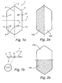
- FIG. 1 a and 1 b an embodiment of the inventive opening device 1 is illustrated.
- the opening device 1 comprises a first body 4 extended along a first folding axis 2, and a locking member 5 disposed on the body 4.
- the first body 4 can be made of a rigid, yet pliable plastics material, such as PET plastic, and can have a thickness within the range of 0.1-1 mm.
- the first body 4 can have an elongated shape having parallel long sides, and short sides which are symmetrically bevelled.
- the corners of the first body 4 are rounded to avoid scratch injuries to a user during handling of the inventive opening device 1.
- first body can be given a number of other configurations and that the first body can thus be given a rectangular shape or be provided with asymmetrically bevelled short sides, such as chamfered or straight cut short sides.
- the first body 4 is manoeuvrable between a basic position for allowing opening of the package and a sealing position corresponding to a resealed state of the package, in which sealing position the said first body 4 is folded about the said first folding axis 2.
- a first hinge joint 6 having an extent which coincides with the said first folding axis 2 is configured in the said first body 4.
- the first hinge joint 6 has a w-shaped cross section, as can be seen from the detached partial enlargement in Fig 1b , but it will be appreciated that the first hinge joint 6 can be configured differently, such as with a v-shaped cross section.
- first hinge joint 6 which allows a well-defined folding about the first folding axis 2 for manoeuvring of the first body 4 into the said sealing position.
- the first body 4 has a contact surface 8, on which the said locking member 5 is disposed, and an application surface 9, facing away from the contact surface 8, by which the said opening device 1 can be applied to the package.
- the application surface 9 may be partly or preferably entirely covered by an adhesive (not shown) for enabling application of the opening device 1 to the package.
- the adhesive may be in the form of an adhesive layer in the form of a hot melt adhesive, also known as hot glue.
- the adhesive layer may be activated by exposure to heat.
- the contact surface 8 has two sub portions 10a, 10b, which are disposed on one side each of the first hinge joint 6 and which, when the first body 4 is in the said sealing position, are directly facing each other.
- the locking member 5, which according to the present invention is disposed in at least one of the said sub portions 10a, 10b, is designed, when activated, to act between the said sub portions 10a, 10b so as to detain the first body 4 in the said second position.
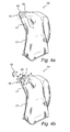
- the sub portions 10a, 10b of the contact surface 8 are illustrated schematically in Fig 3a , to which reference is now made.
- the locking member 5 is configured in one piece with the first body 4 and is designed for mechanical and point locking of the body 4 in the said sealing position. More precisely, the locking member 5 comprises two male members 11, which by snap action can be brought into releasable locking engagement with their respective female member 12. Each pair of male and female members 11, 12 thus forms a push-button-like construction and the locking member 5 is thus activated by the pairs of male and female members 11, 12 being pressed one against the other in connection with the manoeuvring of the first body 4 into its sealing position.
- the male members 11 are disposed on a first 10a of the said sub portions of the contact surface 8 and the female members 12 are disposed on a second 10b of the sub portions of the contact surface 8. It will be appreciated that the number of pairs of male and female members 11, 12 may also be less than or more than two.
- the locking member 5 may be configured differently.
- the locking member may be designed for mechanical and linear locking of the body in its sealing position.
- Such a locking member may comprise an elongated male member, which by snap action can be made to engage with an elongated female member.
- the locking member may alternatively be configured separately in relation to the first body.
- the locking member may be configured in the form of an adhesive which is disposed on one of the two sub portions of the contact surface, which adhesive releasably adheres to the second of the two sub portions of the contact surface by manoeuvring of the first body into its sealing position.
- the embodiment shown of the inventive opening device 1 is further manoeuvrable between the said basic position and an opening position, corresponding to an opened-up state of the package, by folding about a second folding axis 3 extending transversely to the said first folding axis 2.
- a second hinge joint 7 having an extent which coincides with the second folding axis 3 is configured in the said first body 4.
- the second hinge joint 7 can have a v-shaped cross section.
- the second folding axis 3 can have an extent at right angles to the extent of the first folding axis 2, but it will be appreciated that the second folding axis 3 can also extend transversely to the first folding axis 2 with other angular relationships.
- the second hinge joint 7 is configured such that the application surface 9 has, in the opening position of the first body 4, two sub portions 13a, 13b angled relative to each other.
- the first hinge joint 6 and the second hinge joint 7 thus allow well-defined folding of the first body 4 in opposite directions.
- the first hinge joint 6 allows the first body 4 to be folded in such a direction that the sub portions 10a, 10b of the contact surface 8 are angled and are also turned towards each other, whilst the second hinge joint 7 allows the first body 4 to be folded in such a direction that the sub portions 13a, 13b of the application surface 9 are angled relative to each other.
- first and a second hinge joint 6, 7 in the said first body 4 results in the first body 4 acquiring a bistable character.
- the first hinge joint 6 When the first body 4 is in its basic position, the first hinge joint 6 thus allows folding about the first folding axis 2, at the same time as the second hinge joint 7 allows folding about the second folding axis 3.
- the bistable character of the first body 4 means, however, that once folding has been initiated about one of the first and the second folding axes 6, 7, i.e. once the first body has been manoeuvred from its basic position, folding about the second of the first and second folding axes 6, 7 is not allowed.
- Fig 3a-c the first body 4 of the inventive opening device 1 is illustrated in its three different positions.
- the first body 4 of the opening device 1 is shown in its basic position, which corresponds to an unaffected position of the first body 4.
- the basic position represents a position which allows resealing or opening-up of the package, i.e. manoeuvring of the first body 4 into either its sealing position or its opening position.
- Fig 3b the first body 4 of the opening device 1 has been manoeuvred from the basic position into the said sealing position by folding about the first folding axis 2.
- the first hinge joint 6 ensures that the folding is well-defined about the said first folding axis 2.
- the opening device 1 could also be configured without the first hinge joint 6.
- the first body 4 of the opening device 1 is here dimensioned such that it has the necessary rigidity, whilst it can still be bent about the first folding axis 2.
- the absence of a first hinge joint 6 means, however, that the folding is not as well-defined.
- the locking member 5 is configured such that its pair of male and female members 11, 12 engage with each other under snap action and releasably lock the first body 4 in the sealing position.
- the sealing position represents a resealed state of the package.
- each male member 11 is configured in the form of a projection and each female member 12 is formed by an opening in a protrusion.
- Both the projections and the protrusions jut out from the contact surface 8 and the locking member 5 hereby forms a spacer element 4 which mutually separates the sub portions 10a, 10b of the contact surface 8 when the male members 11 engage with the female members 12 in the sealing position of the first body 4.
- This separation is illustrated in Fig 3b by means of the distance D.
- Fig 3c the first body 4 of the opening device 1 has been manoeuvred from the basic position into the said opening position by folding about the second folding axis 3.
- the second hinge joint 7 ensures that the folding is well-defined about the said second folding axis 3.
- the third position represents an opened-up state of the package.
- the opening device 1 could also be configured without the second hinge joint 7.
- the first body 4 of the opening device 1 is here dimensioned such that it has the necessary rigidity, whilst it can still be bent about the second folding axis 3.
- the absence of a second hinge joint 7 means, however, that the folding is not well-defined.
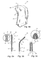
- the inventive opening device 1 allows resealing of flexible packages, and the opening device will be described below with reference to a first embodiment of an inventive package 15 according to Fig 4a-4e , to which reference is now made.
- the first embodiment is a flexible package 15 of the collapsing type, also referred to as a stand-up pouch.
- This type of package is suitable for liquid products and, as shown in the figures, can comprise a gas-filled handle.
- An inventive opening device 1 of the type which has been described above with reference to Fig 1 a and b and Fig 3a-c is applied to the package 15 in an opening portion 16 of the package, which opening portion 16 is formed by two opposing side walls 17 of the flexible package 15 in a corner section of the same.
- the opening portion 16 of the flexible package comprises in the unopened state of the package an end tab 18, which for initial opening of the package is separable from the package 15 by detachment along a separation line 19.
- the package 15 is shown in its unopened state in Fig 4a .
- the first body 4 of the opening device 1 is disposed on one of the said opposing side walls 17 adjacent to the end tab 18 of the opening portion 16, and, more precisely, is disposed on that side of the separation line 19 situated opposite the end tab 18, adjacent to and parallel with this same separation line.
- the separation line 19 may be configured as an initiation for facilitating detachment of the end tab 18 from the package 15.
- the initiation may comprise treated and untreated portions.
- the treated portions may be configured as weakenings, perforations or the like.
- the opening device 1 can be applied to the package 15 by the use of adhesive or by a heat-sealing process, or by some other suitable process.
- the application surface of the opening 1 device may comprise an hot melt adhesive layer in order to facilitate application.
- the opening device is produced separately from the package, production of preformed packages which can be distributed in roll form to a filling plant, such as a dairy, is allowed. Such a roll of preformed packages may then be used in a filling machine to produce filled packages.
- the inventive opening device may in this case be applied to the package in the filling machine.
- the opening device may be applied to the package before, during or after the filling thereof.
- Fig 4b the end tab 18 has been separated from the package 15 for initial opening of the same, whereby an opening 20 is formed in the opening portion 16, which opening 20 allows a content housed in the package 15 to be poured out or dispensed.
- the opening device 1 is disposed adjacent to and parallel with the said opening 20.
- the opening device 1 is illustrated with its first body 4 in the basic position, which, as previously described, allows opening of the package 15.
- Fig 4c the package 15 is illustrated in an opened-up state.
- the first body 4 of the opening member 1 has here been manoeuvred from the basic position into the opening position by folding about the second folding axis 3, which folding is controlled by the second hinge joint 7.
- the manoeuvring is expediently realized by the user, with a thumb and index finger grip, pressing the two opposing short sides of the opening device 1 one against the other such that folding takes place about the second folding axis 3.
- the opening device 1 is disposed on one side wall 17 of the package 15, part of this will accompany the opening device 1 during folding about the second folding axis 3, and will be separated from the second side wall 17, which can be made to bulge in the opposite direction.
- Fig 4c it can be seen how the opening 20 in the opening portion 16 is opened up and acquires a well-defined pouring area when the first body 4 of the opening device 1 assumes the said opening position.
- the opening position does not represent an exactly defined position, but is constituted by a position which can vary from one time to another.
- the purpose of the opening position is to achieve a pouring area for the opening 20 in the opening portion 16.
- the first body may able to assume and maintain the opening position in response to a force load. This force load can be exerted by the product housed in the package, in connection with the performance of a pouring motion when the product reaches the opening portion 16 of the package.
- first body 4 of the opening device 1 Due to the bistable nature of the opening device 1, folding of the first body 4 of the opening device 1 about the said first folding axis 2 is not allowed as long as the first body 4 of the opening device 1 is in the opening position. It should here be noted that the first body 4 is not fully folded about the second folding axis 3 in the third position, which is also why the bistable character is maintained in the opening position despite the fact that the second hinge joint 7, in the embodiment shown, extends transversely to the first hinge joint 6 at a right angle.
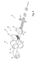
- Fig 4d and 4e the process for resealing the opened package 15 is shown.
- the first body 4 of the opening device 1 is returned from the opening position into the basic position by folding about the second folding axis 3 (not shown).
- the first body 4 is folded about the first folding axis 2, and in Fig 3d it is shown how the folding has been started and in Fig 3e the first body 4 is shown in the sealing position following completed folding.
- the locking member 5 has here been activated and thus ensures that the first body 4 is detained in the said sealing position.
- the bistable nature of the opening device 1 Due to the bistable nature of the opening device 1, folding of the first body 4 of the opening device 1 about the said second folding axis 3 in connection with the folding of the first body 4 about the first folding axis 2 is not allowed. It should here be noted that the first body 4 is fully folded about the first folding axis 2 in the sealing position. Since the second hinge joint 7, in the embodiment shown, extends transversely to the first hinge joint 6 at a right angle, the bistable character of the first body may cease when the first body assumes the sealing position.
- the opening device 1 and its first body 4 are disposed on one side wall 17 of the package 15, part of this side wall 17 will be folded, together with the opening device 1, in the course of the folding about the first folding axis 2 and will thus also drag with it part of the second side wall 17. Consequently, manoeuvring of the first body 4 of the opening device 1 from the basic position into the sealing position causes an end section comprising the said opening 20 in the opening portion 16 to be bent over the first folding axis 2, with the result that the package 15 is resealed, as can thus be seen from Fig 4e .
- the opening device 1 can be configured such that it has a length L which substantially conforms to a width W of the opening portion 16 in the same position, that is to say measured along a line coinciding with the second folding axis 2. More precisely, the sub portions 10a, 10b of the contact surface 8 of the first body 4 adjoin each other along a boundary portion extending along substantially the full width W of the opening portion. Preferably, the length of the opening device 1 somewhat exceeds the width W of the opening portion 16. It is hereby ensured that a relatively tight resealing is achieved, which has a positive effect on the taste and shelf-life of the product enclosed in the package 15. A tight resealing further minimizes the risk of spillage if the package were to overturn.
- the first hinge joint 6 configured in the first body 4 of the opening device 1 may have, as previously described, a w-shaped cross section.
- the advantage with a first hinge joint 6 which is configured in this way will be described below in greater detail with reference to Fig 5a-5c , which schematically show the inventive opening device 1 applied to one side wall 17 of the package 15 adjacent to the opening 20 in the opening portion 16.
- the first hinge joint 6 of the first body has a w-shaped cross section, which can be said to comprise two legs 21 and an intervening ridge 22, as can be clearly seen from the detached partial enlargement in Fig 5a , in which the w-shaped cross section is marked.
- the "free" ends of the legs 21 of the cross section connect to one half each of the first body 4 of the opening device 1.
- the w-shaped cross section is oriented such that the ridge 22 is facing towards the side wall 17 of the package 15.
- Fig 5a the opening device 1 is illustrated with its first body 4 in the basic position.
- Fig 5b it is illustrated how a user has started acting upon the opening device 1 to manoeuvre the first body 4 from its basic position into the sealing position, wherein the first hinge joint 6 controls the folding about the first folding axis 2. It can here be seen how that part of the first body 4 which is folded drags with it the side wall 17 directly connected thereto, which in turn drags with it the second of the side walls 17. By folding of the first body 4 about the first folding axis 2, the said end section of the opening portion 16 will consequently be folded over the said first folding axis 2.
- Fig 5c it is illustrated how the first body 4 of the opening device 1 has been manoeuvred into the sealing position, in which the locking member 5 has been activated in order to maintain the said sealing position.
- the side walls 17, and the thereby defined opening portion 16, are folded about the first folding axis 2. From the detached partial enlargement in Fig 5c , it can be seen how the side walls 17 are stretched and are pressed against the ridge 22 of the w-shaped cross section of the first hinge joint 6 when the first body 4 assumes the said sealing position. This stretching and pressing helps to increase the reliability of the resealing capability of the opening device 1.
- the hinge joints may be formed by a thermo forming operation.
- the w-shape of the first hinge joint 6 may be accomplished such that material is moved from the recesses towards the ridge, which consequently can be made to protrude from the contact surface 8 of the first body 4.
- the legs of the w-shaped cross section are angled. However, the legs may be perpendicular towards the contact surface 8. As a consequence, no material will in this case be displaced in a direction from the ridge in connection with forming of the first hinge joint by a thermo forming operation.
- inventive opening device 1 does not just need to be used in combination with packages of the above-described type.
- an inventive opening device 1 is disposed in an opening portion 16, which is formed by two opposing side walls 17 of the flexible package 15' in a corner section of the same.
- the opening device 1 which, as previously, comprises a first body 4, is more precisely disposed on one of the said opposing side walls 17 adjacent to an end tab 18 of the opening portion 16, which end tab 18 is separable from the package 15' by detachment along a separation line 19.
- the opening device 1 is disposed on that side of the separation line 19 situated opposite the end tab 18, adjacent to and parallel with this same separation line.
- a flexible resealable package 15' according to the said second embodiment is well suited to a particulate content, such as peanuts or sweets. It will be appreciated, however, that this type of package can also hold other types of content, such as a liquid content.
- Fig 6a the package 15' is shown in an unopened state, and in Fig 6b the end tab 18 has been separated along the indicated separation line 19, which enables the package 15' to be opened up by manoeuvring of the opening device 1 into the opening position of the first body 4 in a manner corresponding to that which has been described above in connection with the first embodiment of a flexible resealable package 15, or by manoeuvring of the opening device 1 into the sealing position of the first body 4 in order to reseal the package 15', as is also shown in Fig 6b .
- inventive opening device 1 does not necessarily have to be applied in an opening portion forming part of a corner section of the package.
- Fig 7a-b to which reference is now made, a flexible resealable package 15" according to a third embodiment is illustrated.
- the package 15" has an opening portion 16 defined by two opposing side walls 17 of the package 15".
- the opening portion 16 comprises an end tab 18 forming a top portion of the package 15", which end tab 18 is separable from the package 15" along a separation line 19.
- the opening device 1 comprising a first body 4 is disposed in the opening portion 16 adjacent to its end tab 18 and is parallelly arranged with respect to the said separation line 19.
- the opening device 1 has a length L which substantially conforms to the width W of the opening portion 16 measured along a line coinciding with the second folding axis 2. It will be appreciated that, for a rectangular package such as that which is shown in the figures, this width W corresponds to the width of the package itself.
- the package 15" according to the said third embodiment is shown in Fig 7a in an unopened state and in Fig 7b in a resealed state.
- the first body 4 of the opening device 1 has in the embodiment shown a rectangular shape, i.e. the first body 4 has straight cut short sides.
- the first body 4 of the opening device 1 also has two further hinge joints 35, 36, which are each disposed in a respective end portion of the first body 4.
- the further hinge joints 35, 36 extend transversely to the first hinge joint 2.
- the purpose of the further hinge joints 35, 36 is to facilitate the manoeuvring of the inventive opening device.
- the hinge joints 35, 36 delimit, more precisely, a gripping tab at the respective end of the first body 4, which gripping tabs can be gripped by a user in connection with manoeuvring of the first body into its opening position.
- the first body does not in the embodiment shown have a second hinge joint which controls the folding about the second folding axis in connection with manoeuvring of the body into its opening position.
- a fourth embodiment of an inventive resealable flexible package 15"' which comprises an opening portion 16 defined by two opposing side walls 17 of the package 15"', is illustrated.
- the opening portion 16 forms part of a top portion of the package 15'" and is openable by separation of the side walls 17 of the package 15'" in order to break a transverse edge seal 23 along which the two side walls 17 of the package 15'" are mutually connected.
- the opening device 1 is disposed in the opening portion 16, parallel with the said edge seal 23.
- the package 15'" according to the said fourth embodiment is shown in Fig 8a in an unopened state, in 8b in an opened-up state and in Fig 8c in a resealed state.
- the opening device is illustrated with two further hinge joints 35, 36 of the first body 4, which further hinge joints 35, 36 delimit their respective gripping tab in order to facilitate the manoeuvring of the opening device 1.
- FIG. 9 shows a production line 24 comprising a punching station 25, a forming station 26 and a separating station 27.
- the forming station 26 comprises a heating unit 28 and a pressing unit 29.
- the material from which the opening devices shall be produced is supplied in the form of a roll 30 from which a material web 31 is unrolled and is led to the various stations.
- the material web 31 initially reaches the punching station 25, which in the embodiment shown comprises a rolling press 32 which engages with the side edges of the material web 31 in order to punch out a profile which meets the desired shape of the short sides of the opening devices.
- the material web 31 thereafter reaches the heating unit 28 of the forming station 26, in which the material web 31 is heated to a temperature necessary for thermoforming.
- a temperature necessary for thermoforming In practice, it has shown to be suitable to heat a material web made of PET to a relatively low thermoforming temperature, such as 100°C.
- a tool 33 comprising two tool halves engages with the heated material web 31 for thermoforming thereof.
- the tool 33 is thus configured such that, upon engagement with the material web 31, it thermoforms hinge joints and locking members of the respective opening device.
- the tool 33 can also comprise cooling members for cooling the material web following completed thermoforming. Alternatively, cooling members, should such be required, can be arranged separately from the forming station 26.
- the material web 31 reaches the separating station 27 and in the embodiment shown a knife member 34 engages with the material web 31 for detachment of individual opening devices 1.
- heating unit 28 and the pressing unit 29 can be integrally configured. It will also be appreciated that the separating station 27 can be integrated in the forming station 26.
- the punching station can be dispensed with.
- the short sides of the opening device may be realized by preformed side edges of the material web.
- the separating station can be designed to cut all sides of the respective opening device.
- the separating station may be dispensed with.
- the web of interconnected opening devices may be rolled up in order to be supplied in roll-form to a filling machine.
- the production line may be arranged to produce a web of interconnected opening devices comprising a plurality of opening devices in the transverse direction of the web.
- a roll comprising such a web of interconnected opening devices may be used in a filling machine arranged for filling packages in parallel fillings stations.
- the production line may also comprise an adhesive application station.
- the adhesive application station may be arranged to apply an adhesive layer partly or preferably entirely covering the application surface of each opening device.
- the adhesive layer may be in the form of a hot melt adhesive, also known as hot glue.
- the adhesive layer may be formed with an undulated or wave-formed surface.
- the opening device can be applied to the package in connection with or following the production of the package.
- the filling machine may comprise an applicator for application of said opening devices which as mentioned above may be supplied in said roll-form.
- the applicator may comprise a knife or the like arranged to separate a single opening device from the web of interconnected opening devices.
- the knife may optionally be arranged to cut the contour of the opening devices to suitable shape.
- the separating station can further comprise an indexable holder, which, following separation of an opening device, moves the separated opening device into a position in which the opening device can be applied in the opening portion of a filled package.
- the applicator may comprise a heater arranged to activate the adhesive layer.
- the heater may be a radiation-heater or a hot-air heater. If the surface of the adhesive layer is undulated or wave-shaped, the ridges of the surface will accumulate heat and ensure that the adhesive layer is still active in connection with application of the opening device on a package.
- the heater may be in the form of a contact heater which is pressed against the adhesive layer.
- the contact ensures controlled heat transfer to the adhesive layer and may be provided with a surface treatment in order to prevent the adhesive layer from adhering to the contact heater.
- the contact heater may be provided with a surface profile in order to accomplish the undulated of wave-shaped surface of the adhesive layer.
- the heater may affect the hinge joints of the opening device.
- the bottom of the recesses and the top of the ridge may be rounded as a consequence of the heat exposure.
- the rounded bottom of the recesses may negatively affect the folding capability of the opening device.
- the filling machine may comprise equipment which allows the production of opening devices, such as equipment which allows execution of the process described with reference to Fig 8 .
- the separating station can here be designed to cut all sides of the respective opening device in connection with the separation thereof.
- the separating station can further comprise an indexable holder, which, following separation of an opening device, moves the separated opening device by a rotary motion into a position in which the opening device can be applied in the opening portion of a filled package.
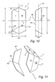
- the opening device 1 comprises a first body 4, as described above with reference to Fig 1-3 , and a second body 40.
- the first body 4 and second body 40 of the opening device 1 are illustrated in Fig 10 .
- the second body 40 extends along a longitudinal axis 41 and has a second application surface for allowing the second body 40 on a package.
- the second body 40 is further manoeuvrable between an unfolded position and a folded position by folding about a third folding axis 42.
- the opening device 1 is illustrated with its first body 4 in its third position and its second body 40 in its folded position.
- the third folding axis 42 of the second body 40 can extend, as in the embodiment shown, at right angles to the longitudinal axis 41, but it will be appreciated that it is also possible to arrange the third folding axis 42 such that this extends at a non-right angle in relation to the said longitudinal axis 41.
- the second folding axis 3 of the first body 4 can be angled in relation to the third folding axis 42 of the second body 40 such that the said folding axes are parallel in a state applied to a package.
- a third hinge joint 43 having an extent which coincides with the said third folding axis 42 can be configured in the second body 40.
- the third hinge joint 43 can have a v-shaped or w-shaped cross section.
- the second body 40 further has a width B2 which is less than half the width B1 of the first body 4.
- the second body 40 further has a length L2 which is equal to or less than the length L1 of the first body 4.
- first body 4 and the second body 40 can be configured other than is shown in the figures for adaptation to the geometry in the opening portion of the package on which the opening device 1 is intended to be disposed.
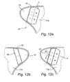
- FIG 12a-12c an opening portion 16 of a flexible package is illustrated, which opening portion 16 is formed by two opposing side walls 17a, 17b of the flexible package in a corner section of the same.
- An opening device 1 according to the said further embodiment is disposed in the said opening portion 16.
- the opening portion 16 of the flexible package comprises in the unopened state of the package an end tab 18, which for initial opening of the package is separable from the package by detachment along a separation line 19.
- the first body 4 of the opening device 1 is disposed on a first 17a of the said opposing side walls 17a, 17b, adjacent to the end tab 18 of the opening portion 16, and, more precisely, is disposed on that side of the separation line 19 situated opposite the end tab 18, adjacent to and parallel with this same separation line, as can be clearly seen from Fig 12a .
- the second body 40 of the opening device 1 is disposed on a second 17b of the said opposing side walls 17a, 17b, adjacent to the end tab 18 of the opening portion 16, and, more precisely, is disposed on that side of the separation line 19 situated opposite the end tab 18, adjacent to and parallel with this same separation line, as can be clearly seen from Fig 12b .
- the separation line 19 can be configured as a initiation for facilitating detachment of the end tab 18 from the package.
- the initiation can comprise treated and untreated portions.
- the treated portions can be configured as weakenings, perforations or the like.
- the opening device 1 can be applied in the opening portion 15 by the use of adhesive, such as a hot melt adhesive as described above, or by a heat-sealing process, or by some other suitable process.
- adhesive such as a hot melt adhesive as described above, or by a heat-sealing process, or by some other suitable process.
- the second body 40 has a length L2 which is equal to or less than the length L1 of the first body 4 and has a width B2 which is less than half the width B1 of the first body 4. It hereby becomes possible to dispose the second body 40 within a region on the second side wall 17b, which region, in the state of the opening device 1 applied to the package, is defined by the contour of one sub portion 10a of the contact surface 8 of the first body 4, as can be clearly seen from Fig 12c .
- the bodies 4, 40 are mutually arranged such that the third folding axis 42 of the second body 40 is parallelly displaced in relation to the second folding axis 3 of the first body 4.
- the folding axes 3, 42 can be parallelly displaced with respect to each other with a distance apart A within the range 1-3 mm, but it will be appreciated that the parallel displacement can be greater or less than this. In certain applications, the parallel displacement can be wholly dispensed with.
- the first body 4 is manoeuvred into its opening position and the second body 40 into its folded position, as is illustrated in Fig 13a and 13b .
- the first body 4 is manoeuvred into its opening position and the second body 40 into its folded position simultaneously, by a user, with a thumb and index finger grip, pressing opposing short sides of the opening device 1 one against the other such that folding takes place about the second folding axis 3 and about the third folding axis 42 respectively.
- the bending axes 3, 42 in the embodiment shown are parallelly displaced, it is ensured that the folding takes place in opposite directions. From the figures, it can be seen how the opening 20 in the opening portion 16 is opened up and acquires a well-defined pouring area having a contour which assumes the form of a parallelogram.
- the first body 4 and the second body 40 are configured so that these do not extend beyond the connecting portion in which the side walls 17a, 17b of the package are mutually connected, but keep within the width of the opening portion.
- One of the said bodies 4, 40 could be permitted to have an extent beyond the said connecting portions, but the fact that at least one body lacks such an extent ensures that the two bodies 4, 40 do not counteract each other in connection with opening of the package into its opened-up state.
- the said further embodiment of the inventive opening device 1 minimizes the incidence of drips after a completed pouring process.
- Surface tension effects namely imply that remaining product residues can be better detained between the side walls 17a, 17b in the bottom corners 44 of the opening 20.
- the opening device produces, however, a lower opening angle ⁇ of the opening 20, which lower opening angle ⁇ is large enough to overcome these surface tension effects. It is thus the second body 40 which, when the package is opened into its opened-up state, strives to angle the second side wall 17b away from the first side wall 17a to a sufficient degree to allow the attainment of a lower opening angle ⁇ which is sufficiently large.
- the lower opening angle ⁇ which is required to overcome the surface tension effects is dependent on the product which is housed in the package.
- the lower opening angle ⁇ needs to be greater for milk than for water.
- the lower opening angle ⁇ can be within the range 15-65° or, more preferably, within the range 35-55°.
- the opening device 1 does not need to be configured such that the opening position of the first body 4 and the folded position of the second body 40 are identical in each manoeuvring operation for opening up a package. This means that the lower opening angle ⁇ can be permitted to vary somewhat with repeated openings of the package into its opened-up state.
- Fig 14 the pouring portion of the package is illustrated in the resealed state of the package.
- the second body 40 is disposed within or inside a region defined by one sub portion 10a of the contact surface 8 of the first body 4, it is possible to manoeuvre the first body 4 into its second position by folding about the first folding axis 2 without the second body 40 preventing the said manoeuvring.
- the fact that the second body 40 is smaller than the said sub portion 10a also implies that the second body 40 can be placed at a distance from the first folding axis 2, as can be seen from the figure. It is hereby ensured that the second body 40 does not act upon the side walls 17 when these are folded in connection with resealing of the package, which enables repeated, substantially liquid-tight resealing.
- the above-described process for producing an opening device can be adapted such that the process also allows production of the second body of the opening device according to the above-described further embodiment.
- the package such that its geometry helps the opening device to be acted upon, when its locking members have not been activated, such that the package assumes its opened-up state.
- This can be realized, for example, in such a way that the opening portion is given a somewhat protruding geometry such that the package, under the influence of gravity, forms a fold which serves to separate the side walls in the opening portion. The fold will thus serve for manoeuvring of the first body into its opening position and, where appropriate, of the second body into its folded position, which corresponds to the opened-up state of the package.
Landscapes
- Engineering & Computer Science (AREA)
- Mechanical Engineering (AREA)
- Packages (AREA)
- Bag Frames (AREA)
- Cartons (AREA)
- Supplying Of Containers To The Packaging Station (AREA)
- Closures For Containers (AREA)
Description
- The present invention relates to a resealable opening device for a flexible package and to a package comprising such an opening device.
- There are a large number of different goods which are packed in flexible packages produced from a film material.
- The packages may house particulate goods, such as crisps, peanuts or coffee beans, and in this case often have a so-called pillow shape.
- Alternatively, the packages may house liquid goods, such as milk, water or wine, and are here normally of the so-called stand-up pouch type, also referred to as collapsible-type packages. Packages of the stand-up pouch type may, of course, also be used for particulate goods.
- Packages or containers of this flexible type are normally opened by the removal of an end tab or corner portion. Alternatively, they can be opened by a user pulling apart the side walls of the package in order thereby to break an upper transverse seal of the package.
- Common to these flexible packages is that there is often a need to be able to reseal the package once it has been opened. By resealing the package, the risk of accidental spillage of the content of the package is reduced, whilst the resealing often has a positive effect on the shelf life of the content.
- This resealing can be realized with the aid of clips, screw caps, rubber bands, tapes, etc. It has nevertheless proved difficult to provide an opening device which is cheap, reliable, user-friendly and, moreover, relatively easy to apply to the package in connection with the filling thereof. Opening devices for flexible packages are known, for example, from
US 3 815 810 ,US 6 296 388 andWO2004/092022 . -
US 3 815 810 discloses an opening device in the form of a thin-walled body which is applied to a side wall of the package. For resealing of the package, an end section comprising an opening is folded, and the end section is locked in the folded state by means of tabs of the body which are folded up over the said end section. -
US 6 296 388 discloses a foldable thin-walled body which is intended for application inside an opening of the package. -
WO2004/092022 discloses various types of opening devices of the zip-lock type, which are stamped in place in the package adjacent to its opening. - It can thus be seen that there is a need for an improved resealable opening device for flexible packages.
- In view of the above, it is an object of the present invention to provide an improved resealable opening device for a flexible package.
- It is also an object of the invention to provide a flexible package comprising a resealable opening device of this kind.
- According to the present invention, a resealable opening device having the distinguishing features defined in
Claim 1 and a package having the distinguishing features defined inClaim 21 are thus provided. Embodiments emerge from the sub-claims dependent on the respective main claims. - More precisely, according to the present invention, an opening device for a flexible package having an opening portion which is defined by two side walls and has a width is provided, which opening device is intended to be disposed in the opening portion of the package adjacent to an opening, formed upon initial opening of the package, for opening and closing thereof, which opening device comprises a thin-walled first body with a contact surface and a first application surface opposite thereto for allowing application of the said first body in the opening portion to a first of the said two side walls, and a locking member. The first body is manoeuvrable, by folding about a first folding axis, between a basic position and a sealing position, in which sealing position the said contact surface has sub portions directly facing each other. Said sub portions adjoin each other along a boundary portion which is designed to extend along substantially the full width of the opening portion, and the said locking member is designed for releasable locking of the body in the said sealing position. The locking member is disposed in at least one of the sub portions of the contact surface and is designed to act between the said sub portions in order to achieve said releasable locking.
- An improved, resealable opening device for a flexible package is hereby provided. The opening device comprises a foldable first body and a locking member which allows locking of the first body in the folded position, i.e. the sealing position, and is thus relatively easy and cheap to produce. Since the body of the opening device is thin-walled and is also foldable about the first folding axis, the body can be made substantially flat and is hence relatively easy to apply in the opening portion of a package. The inventive opening device also allows reliable resealing of a flexible package. The opening device is here arranged in the opening portion of the flexible package by placing the application surface of the body against one of the two side walls of the package which define the opening portion. The opening device can be applied to the package with the aid of an adhesive or by a heat treatment process or the like. By manoeuvring the first body of the opening device from its basic position into its sealing position, i.e. by folding the first body about the first folding axis, it becomes possible to fold an end section of the opening portion over the said first folding axis, whereby the package is resealed. By suitably adapting the length of the first body in relation to the width of the opening portion, it is possible to achieve resealing with a high level of reliability. More precisely, it is assured that the sub portions adjoin each other along said boundary portion, which is designed to extend along substantially the full width of the opening portion. Preferably, it is assured that the length of the first body somewhat exceeds the width of the opening portion, whereby a substantiaiiy liquid-tight resealing can be achieved.
- According to one embodiment, a first hinge joint having an extent which coincides with said first folding axis may be configured in the said first body. It is hereby ensured that the folding about the first folding axis during manoeuvring of the first body from the basic position into its sealing position is well-defined. The first hinge joint can here have a v-shaped or w-shaped cross section. In particular, the use of a w-shaped cross section on the first hinge joint can make it possible to achieve such tight resealing that a package housing a liquid content can be turned up and down without leakage after it is resealed.
- According to another embodiment of the present invention, the said locking member may form a spacer element which mutually separates the sub portions of the contact surface in the sealing position of the first body. The manoeuvring of the first body of the opening device from the sealing position into the basic position, which corresponds to opening of the package from the resealed state, is hereby facilitated. The spacer element namely enables the finger of a user to be introduced between the two mutually facing sub portions in order to prise these apart and thereby release the locking member.
- According to another embodiment of the present invention, the said first body may be manoeuvrable between the said basic position and an opening position by folding about a second folding axis extended transversely to the said first folding axis. By manoeuvring the first body into the opening position, it becomes possible to arrange the package in an opened-up state which facilitates dispensing of the content of the package. A second hinge joint having an extent which coincides with the said second folding axis can here be configured in the said first body. It is hereby ensured that the folding about the second folding axis during manoeuvring of the first body from its basic position into its opening position is well-defined. The application surface may have, in the opening position of the first body, two sub portions angled relative to each other.
- According to a further embodiment of the present invention, the opening device further comprises a second body extended along a longitudinal axis and having a second application surface for allowing application of the second body in the opening portion to a second of the said two side walls, wherein the second body is manoeuvrable between an unfolded position and a folded position by folding about a third folding axis, the second body being intended for manoeuvring into the said folded position in connection with manoeuvring of the first body into its opening position. The first and second body of the opening device are thus both folded in connection with opening of the package into its opened-up state and it hereby becomes possible to achieve a well-defined opening with a bottom corner having a lower opening angle which is sufficiently large to ensure that product residues, should these be fluid, are not detained in the opening portion under the influence of surface tension effects following completed dispensing of the content by a pouring process. The surface tension effects can vary in dependence on the product, so that the lower opening angle may be adapted to the particular type of product.
- By suitable placement of the second body on the package and suitable configuration of the same, it can be assured that the second body has no bearing when the first body is manoeuvred from its basic position into the sealing position for resealing of the package. In particular, the said first body may have a first width and the said second body can have a second width, wherein the second width is less than half the first width. It hereby becomes possible to apply the second body to the package such that the package can be freely resealed by means of the first body.
- According to another embodiment, the said first body may have a first length and the said second body may have a second length, wherein the second length is equal to or less than the first length. It hereby becomes possible to assure that the first and the second body can be freely manoeuvred into the opening position and second position respectively of the package for arrangement of the package in its opened-up state.
- According to one embodiment, a third hinge joint having an extent which coincides with the said third folding axis may be configured in the said second body. It is hereby ensured that the folding about the third folding axis, when the second body is manoeuvred from its unfolded into its folded position, is well-defined.
- One, some or all of the above-specified hinge joints may have a v-shaped or w-shaped cross section.
- According to a further embodiment of the present invention, the said locking member may be designed for point locking. Alternatively, the locking member may be designed for linear locking.
- According to a further embodiment of the opening device, the said locking member may be designed for mechanical locking. The locking member may be designed for mechanical locking by snap action. As an alternative to mechanical locking, the said locking member may be designed for locking with the aid of an adhesive.
- According to another embodiment of the present invention, the body of the opening device may be made of a plastics material, such as PET, having a thickness within the range of 0.1-1 mm.
- According to yet another embodiment, the application surface may be provided with an adhesive layer comprising a hot melt adhesive. Hereby, an opening device is provided which is non-sticky in room temperature and thus easy to handle. The adhesive layer of the opening device may be activated by exposure to heat in order to allow application on a package. The adhesive layer preferably covers the application surface. By the adhesive layer covering the entire application surface, it may be ensured that an end section of the package is properly folded upon manoeuvring the first body to the sealing position.
- The adhesive layer may have an undulated surface. Hereby the capacity of the adhesive layer to store heat in connection with exposure to heat is enhanced, which may be beneficial in connection with application of the opening device on a package.
- According to the present invention, a flexible package having an opening portion defined by two side walls, comprising an opening device which is disposed in the opening portion adjacent to an opening, formed upon initial opening of the package, for opening and closing thereof, which opening device comprises a thin-walled first body with a contact surface and a first application surface opposite thereto by which the first body is fastened to an external surface of a first of the said side walls of the package, and a locking member, is also indicated. The first body is manoeuvrable, by folding about a first folding axis, between a basic position and a sealing position, in which sealing position said contact surface has sub portions directly facing each other, and the locking member is disposed in at least one of the sub portions of the contact surface and is designed to act between the said sub portions in order to achieve releasable locking of the body in the said sealing position. The first folding axis of the first body is oriented parallel with said opening, and the package is manoeuvrable into a resealed state in which an end section of the opening portion comprising the said opening is folded about the said first folding axis by manoeuvring of the first body into the said sealing position.
- According to one embodiment of the inventive package, the first body of the opening device may be manoeuvrable, by folding about a second folding axis extended transversely to the said first folding axis, between the said basic position and an opening position, wherein the package may be arranged in an opened-up state in which the side walls in the opening portion are separated by manoeuvring of the first body into the said opening position.
- According to a further embodiment, the opening device further may comprise a second body extended along a longitudinal axis and having a second application surface by which the second body is fastened to an external surface of a second of the said two side walls, which second body is manoeuvrable, by folding about a third folding axis, between an unfolded position and a folded position, wherein the package may be arranged in the opened-up state by manoeuvring of the second body into the folded position in connection with manoeuvring of the first body into the opening position.
- According to yet another embodiment, the first body and the second body may be disposed in the opening portion on the first side wall and second side wall respectively of the package such that the second body is situated within a region defined by the contour of one of the said sub portions of the first body. It is hereby ensured that the first body can be manoeuvred into its sealing position so as to reseal the package without influence from the second body.
- According to another embodiment, the second folding axis of the first body may be parallelly displaced in relation to the third folding axis of the second body. By virtue of the fact that the first and the second body are applied with respectively the second and third folding axis parallelly displaced with respect to each other, opening of the package into its opened-up state is facilitated, since the folding is hereby controlled such that the bodies are folded in different directions.
- The advantages which have been specified above with reference to the inventive opening device are in relevant parts also applicable to the inventive flexible package.
- Terms in the claims should generally be interpreted according to their normal meaning within the technical field, unless otherwise expressly stated. All references to "a/the [element, device, component, member, step]" should be interpreted as a reference to at least a presence of the said element, device, component, member, step, etc., unless otherwise expressly stated. The steps of any method which is described herein do not have to be performed in exactly the described order, unless otherwise expressly stated.
- The above, as well as further objects, distinguishing features and advantages of the present invention, will be better understood as a result of the following illustrative and non-limiting detailed description of embodiments of the present invention with reference to the appended drawings, in which the same reference symbols will be used for elements of the same type.
-
Fig 1 a shows a plan view of one embodiment of an opening device according to the present invention. -
Fig 1b shows a side view of the opening device shown inFig 1 a. -
Fig 2a and 2b are plan views which schematically show the sub portions of the contact surface and application surface, respectively, of the first body of the opening device shown inFig 1 . -
Fig 3a shows a perspective view of the opening device shown inFig 1a , in a basic position. -
Fig 3b shows a perspective view of the opening device shown inFig 1a , in a sealing position. -
Fig 3c shows a perspective view of the opening device shown inFig 1a , in an opening position. -
Fig 4a shows a perspective view of a first embodiment of an inventive flexible package, in an unopened state. -
Fig 4b shows a perspective view of the package shown inFig 4a , in an initially opened state. -
Fig 4c shows a perspective view of the package shown inFig 4a , in a opened-up state. -
Fig 4d shows a perspective view of the package shown inFig 4a , in a state when it is about to be resealed. -
Fig 4e shows a perspective view of the package shown inFig 4a , in a resealed state. -
Fig 5a shows a cross-sectional view taken along the line a-a inFig 4b . -
Fig 5b shows a cross-sectional view taken along the line b-b inFig 4d . -
Fig 5c shows a cross-sectional view taken along the line c-c inFig 4e . -
Fig 6a and 6b show a second embodiment of an inventive flexible package, in an unopened and resealed state, respectively. -
Fig 7a and 7b show a third embodiment of an inventive flexible package, in an unopened and resealed state, respectively. -
Fig 8a, 8b and 8c show a fourth embodiment of an inventive flexible package, in an unopened, an opened-up and a resealed state, respectively. -
Fig 9 shows a schematic production line for the production of an inventive opening device. -
Fig 10 shows a plan view of a further embodiment of an inventive opening device. -
Fig 11 shows a perspective view of the opening device shown inFig 10 , in which a first body is shown in an opening position and a second body is shown in a folded position. -
Fig 12a-12c show detached plan views of a flexible package, with the opening device shown inFig 10 applied in an opening portion thereof. -
Fig 13a, 13b show detached perspective views of the package shown inFig 12a-12c , in an opened-up state. -
Fig 14 shows a detached perspective view of the package shown inFig 12a-12c , in a resealed state. - The present invention relates to an opening device for a flexible package and to a flexible package comprising such an opening device.
- By a flexible package is meant a package or container which is made of a flexible material in the sense that the material is pliable. A flexible package of this kind may thus be made of a single-layered or multi-layered film material. The film material may comprise layers of plastic, such as PE, PP, PET, EVOH, and/or aluminium foil. Layers of plastic such as PE or PP may also comprise a filler, such as a mineral material.
- In
Fig 1 a and 1 b, to which reference is made, an embodiment of theinventive opening device 1 is illustrated. - The
opening device 1 comprises afirst body 4 extended along afirst folding axis 2, and a lockingmember 5 disposed on thebody 4. - The
first body 4 can be made of a rigid, yet pliable plastics material, such as PET plastic, and can have a thickness within the range of 0.1-1 mm. - As in the embodiment shown, the
first body 4 can have an elongated shape having parallel long sides, and short sides which are symmetrically bevelled. - According to the embodiment shown, the corners of the
first body 4 are rounded to avoid scratch injuries to a user during handling of theinventive opening device 1. - It will be appreciated that the first body can be given a number of other configurations and that the first body can thus be given a rectangular shape or be provided with asymmetrically bevelled short sides, such as chamfered or straight cut short sides.
- The
first body 4 is manoeuvrable between a basic position for allowing opening of the package and a sealing position corresponding to a resealed state of the package, in which sealing position the saidfirst body 4 is folded about the saidfirst folding axis 2. - In the embodiment shown, a
first hinge joint 6 having an extent which coincides with the saidfirst folding axis 2 is configured in the saidfirst body 4. Thefirst hinge joint 6 has a w-shaped cross section, as can be seen from the detached partial enlargement inFig 1b , but it will be appreciated that thefirst hinge joint 6 can be configured differently, such as with a v-shaped cross section. - In the embodiment shown, it is thus the
first hinge joint 6 which allows a well-defined folding about thefirst folding axis 2 for manoeuvring of thefirst body 4 into the said sealing position. - The
first body 4 has acontact surface 8, on which the said lockingmember 5 is disposed, and anapplication surface 9, facing away from thecontact surface 8, by which the saidopening device 1 can be applied to the package. - The
application surface 9 may be partly or preferably entirely covered by an adhesive (not shown) for enabling application of theopening device 1 to the package. The adhesive may be in the form of an adhesive layer in the form of a hot melt adhesive, also known as hot glue. In connection with application of theopening device 9 to the package, the adhesive layer may be activated by exposure to heat. - The
contact surface 8 has twosub portions first hinge joint 6 and which, when thefirst body 4 is in the said sealing position, are directly facing each other. The lockingmember 5, which according to the present invention is disposed in at least one of the saidsub portions sub portions first body 4 in the said second position. By virtue of the fact that thesub portions contact surface 8 are directly facing each other in the sealing position of thefirst body 4, it is ensured that nothing hinders the lockingmember 5 from acting between the saidsub portions - The
sub portions contact surface 8 are illustrated schematically inFig 3a , to which reference is now made. - In the embodiment shown, the locking
member 5 is configured in one piece with thefirst body 4 and is designed for mechanical and point locking of thebody 4 in the said sealing position. More precisely, the lockingmember 5 comprises twomale members 11, which by snap action can be brought into releasable locking engagement with their respectivefemale member 12. Each pair of male andfemale members member 5 is thus activated by the pairs of male andfemale members first body 4 into its sealing position. - The
male members 11 are disposed on a first 10a of the said sub portions of thecontact surface 8 and thefemale members 12 are disposed on a second 10b of the sub portions of thecontact surface 8. It will be appreciated that the number of pairs of male andfemale members - It will further be appreciated that the locking
member 5 may be configured differently. For example, the locking member may be designed for mechanical and linear locking of the body in its sealing position. Such a locking member may comprise an elongated male member, which by snap action can be made to engage with an elongated female member. - The locking member may alternatively be configured separately in relation to the first body. For example, the locking member may be configured in the form of an adhesive which is disposed on one of the two sub portions of the contact surface, which adhesive releasably adheres to the second of the two sub portions of the contact surface by manoeuvring of the first body into its sealing position.
- The embodiment shown of the
inventive opening device 1 is further manoeuvrable between the said basic position and an opening position, corresponding to an opened-up state of the package, by folding about asecond folding axis 3 extending transversely to the saidfirst folding axis 2. Asecond hinge joint 7 having an extent which coincides with thesecond folding axis 3 is configured in the saidfirst body 4. Thesecond hinge joint 7 can have a v-shaped cross section. - As in the embodiment shown, the
second folding axis 3 can have an extent at right angles to the extent of thefirst folding axis 2, but it will be appreciated that thesecond folding axis 3 can also extend transversely to thefirst folding axis 2 with other angular relationships. - The
second hinge joint 7 is configured such that theapplication surface 9 has, in the opening position of thefirst body 4, twosub portions - The
sub portions application surface 9 are illustrated schematically inFig 2b , to which reference now also is made. - The
first hinge joint 6 and the second hinge joint 7 thus allow well-defined folding of thefirst body 4 in opposite directions. Thefirst hinge joint 6 allows thefirst body 4 to be folded in such a direction that thesub portions contact surface 8 are angled and are also turned towards each other, whilst thesecond hinge joint 7 allows thefirst body 4 to be folded in such a direction that thesub portions application surface 9 are angled relative to each other. - The configuration of a first and a
second hinge joint first body 4 results in thefirst body 4 acquiring a bistable character. When thefirst body 4 is in its basic position, the first hinge joint 6 thus allows folding about thefirst folding axis 2, at the same time as thesecond hinge joint 7 allows folding about thesecond folding axis 3. The bistable character of thefirst body 4 means, however, that once folding has been initiated about one of the first and thesecond folding axes second folding axes - Should the second hinge joint extend transversely to the first hinge joint at an angle different from 90°, it becomes possible to assure that the bistable character of the first body is maintained also in the folded state. In particular, folding about the
second folding axis 7 is precluded when the first body is folded about thefirst folding axis 6 and is in the sealing position. - In
Fig 3a-c , to which reference is now made, thefirst body 4 of theinventive opening device 1 is illustrated in its three different positions. - In
Fig 3a , thefirst body 4 of theopening device 1 is shown in its basic position, which corresponds to an unaffected position of thefirst body 4. The basic position represents a position which allows resealing or opening-up of the package, i.e. manoeuvring of thefirst body 4 into either its sealing position or its opening position. - In
Fig 3b , thefirst body 4 of theopening device 1 has been manoeuvred from the basic position into the said sealing position by folding about thefirst folding axis 2. Thefirst hinge joint 6 ensures that the folding is well-defined about the saidfirst folding axis 2. - It will be appreciated that the
opening device 1 could also be configured without thefirst hinge joint 6. Thefirst body 4 of theopening device 1 is here dimensioned such that it has the necessary rigidity, whilst it can still be bent about thefirst folding axis 2. The absence of a first hinge joint 6 means, however, that the folding is not as well-defined. - The locking
member 5 is configured such that its pair of male andfemale members first body 4 in the sealing position. The sealing position represents a resealed state of the package. - As can be seen from
Fig 3a , eachmale member 11 is configured in the form of a projection and eachfemale member 12 is formed by an opening in a protrusion. Both the projections and the protrusions jut out from thecontact surface 8 and the lockingmember 5 hereby forms aspacer element 4 which mutually separates thesub portions contact surface 8 when themale members 11 engage with thefemale members 12 in the sealing position of thefirst body 4. This separation is illustrated inFig 3b by means of the distance D. By virtue of the fact that thesub portions first body 4, a user can easily introduce a finger between the saidsub portions member 5 and open theopening device 1. - In
Fig 3c , thefirst body 4 of theopening device 1 has been manoeuvred from the basic position into the said opening position by folding about thesecond folding axis 3. Thesecond hinge joint 7 ensures that the folding is well-defined about the saidsecond folding axis 3. The third position represents an opened-up state of the package. - It will be appreciated that the
opening device 1 could also be configured without thesecond hinge joint 7. Thefirst body 4 of theopening device 1 is here dimensioned such that it has the necessary rigidity, whilst it can still be bent about thesecond folding axis 3. The absence of a second hinge joint 7 means, however, that the folding is not well-defined. Should aninventive opening device 1 without a second hinge joint 7 be applied adjacent to an opening in a flexible package containing a liquid product, the manoeuvring of the first body of the opening member from its basic position into its opening position could be realized by the user performing a pouring motion, whereby the product pressure opens up the opening in the flexible package and thus acts upon the first body of the opening device such that this is bent about the second folding axis. - The
inventive opening device 1 allows resealing of flexible packages, and the opening device will be described below with reference to a first embodiment of aninventive package 15 according toFig 4a-4e , to which reference is now made. - The first embodiment is a
flexible package 15 of the collapsing type, also referred to as a stand-up pouch. This type of package is suitable for liquid products and, as shown in the figures, can comprise a gas-filled handle. - An
inventive opening device 1 of the type which has been described above with reference toFig 1 a and b andFig 3a-c is applied to thepackage 15 in anopening portion 16 of the package, which openingportion 16 is formed by two opposingside walls 17 of theflexible package 15 in a corner section of the same. - The opening
portion 16 of the flexible package comprises in the unopened state of the package anend tab 18, which for initial opening of the package is separable from thepackage 15 by detachment along aseparation line 19. Thepackage 15 is shown in its unopened state inFig 4a . - The
first body 4 of theopening device 1 is disposed on one of the said opposingside walls 17 adjacent to theend tab 18 of the openingportion 16, and, more precisely, is disposed on that side of theseparation line 19 situated opposite theend tab 18, adjacent to and parallel with this same separation line. - The
separation line 19 may be configured as an initiation for facilitating detachment of theend tab 18 from thepackage 15. The initiation may comprise treated and untreated portions. The treated portions may be configured as weakenings, perforations or the like. - The
opening device 1 can be applied to thepackage 15 by the use of adhesive or by a heat-sealing process, or by some other suitable process. As mentioned above, the application surface of theopening 1 device may comprise an hot melt adhesive layer in order to facilitate application. - By virtue of the fact that the opening device is produced separately from the package, production of preformed packages which can be distributed in roll form to a filling plant, such as a dairy, is allowed. Such a roll of preformed packages may then be used in a filling machine to produce filled packages. The inventive opening device may in this case be applied to the package in the filling machine. The opening device may be applied to the package before, during or after the filling thereof.
- In
Fig 4b , theend tab 18 has been separated from thepackage 15 for initial opening of the same, whereby anopening 20 is formed in the openingportion 16, whichopening 20 allows a content housed in thepackage 15 to be poured out or dispensed. As can be seen from the figure, theopening device 1 is disposed adjacent to and parallel with the saidopening 20. - In the figure, the
opening device 1 is illustrated with itsfirst body 4 in the basic position, which, as previously described, allows opening of thepackage 15. - In
Fig 4c , thepackage 15 is illustrated in an opened-up state. Thefirst body 4 of the openingmember 1 has here been manoeuvred from the basic position into the opening position by folding about thesecond folding axis 3, which folding is controlled by thesecond hinge joint 7. The manoeuvring is expediently realized by the user, with a thumb and index finger grip, pressing the two opposing short sides of theopening device 1 one against the other such that folding takes place about thesecond folding axis 3. By virtue of the fact that theopening device 1 is disposed on oneside wall 17 of thepackage 15, part of this will accompany theopening device 1 during folding about thesecond folding axis 3, and will be separated from thesecond side wall 17, which can be made to bulge in the opposite direction. FromFig 4c , it can be seen how theopening 20 in the openingportion 16 is opened up and acquires a well-defined pouring area when thefirst body 4 of theopening device 1 assumes the said opening position. - It will be appreciated that the opening position does not represent an exactly defined position, but is constituted by a position which can vary from one time to another. The purpose of the opening position is to achieve a pouring area for the
opening 20 in the openingportion 16. It will also be appreciated that the first body may able to assume and maintain the opening position in response to a force load. This force load can be exerted by the product housed in the package, in connection with the performance of a pouring motion when the product reaches the openingportion 16 of the package. - Due to the bistable nature of the
opening device 1, folding of thefirst body 4 of theopening device 1 about the saidfirst folding axis 2 is not allowed as long as thefirst body 4 of theopening device 1 is in the opening position. It should here be noted that thefirst body 4 is not fully folded about thesecond folding axis 3 in the third position, which is also why the bistable character is maintained in the opening position despite the fact that thesecond hinge joint 7, in the embodiment shown, extends transversely to the first hinge joint 6 at a right angle. - In
Fig 4d and4e , the process for resealing the openedpackage 15 is shown. To begin with, thefirst body 4 of theopening device 1 is returned from the opening position into the basic position by folding about the second folding axis 3 (not shown). After this, thefirst body 4 is folded about thefirst folding axis 2, and in Fig 3d it is shown how the folding has been started and in Fig 3e thefirst body 4 is shown in the sealing position following completed folding. The lockingmember 5 has here been activated and thus ensures that thefirst body 4 is detained in the said sealing position. - Due to the bistable nature of the
opening device 1, folding of thefirst body 4 of theopening device 1 about the saidsecond folding axis 3 in connection with the folding of thefirst body 4 about thefirst folding axis 2 is not allowed. It should here be noted that thefirst body 4 is fully folded about thefirst folding axis 2 in the sealing position. Since thesecond hinge joint 7, in the embodiment shown, extends transversely to the first hinge joint 6 at a right angle, the bistable character of the first body may cease when the first body assumes the sealing position. - Since the
opening device 1 and itsfirst body 4 are disposed on oneside wall 17 of thepackage 15, part of thisside wall 17 will be folded, together with theopening device 1, in the course of the folding about thefirst folding axis 2 and will thus also drag with it part of thesecond side wall 17. Consequently, manoeuvring of thefirst body 4 of theopening device 1 from the basic position into the sealing position causes an end section comprising the saidopening 20 in the openingportion 16 to be bent over thefirst folding axis 2, with the result that thepackage 15 is resealed, as can thus be seen fromFig 4e . - As in the embodiment shown, the
opening device 1 can be configured such that it has a length L which substantially conforms to a width W of the openingportion 16 in the same position, that is to say measured along a line coinciding with thesecond folding axis 2. More precisely, thesub portions contact surface 8 of thefirst body 4 adjoin each other along a boundary portion extending along substantially the full width W of the opening portion. Preferably, the length of theopening device 1 somewhat exceeds the width W of the openingportion 16. It is hereby ensured that a relatively tight resealing is achieved, which has a positive effect on the taste and shelf-life of the product enclosed in thepackage 15. A tight resealing further minimizes the risk of spillage if the package were to overturn. - The first hinge joint 6 configured in the
first body 4 of theopening device 1 may have, as previously described, a w-shaped cross section. The advantage with afirst hinge joint 6 which is configured in this way will be described below in greater detail with reference toFig 5a-5c , which schematically show theinventive opening device 1 applied to oneside wall 17 of thepackage 15 adjacent to theopening 20 in the openingportion 16. - The
first hinge joint 6 of the first body has a w-shaped cross section, which can be said to comprise twolegs 21 and an interveningridge 22, as can be clearly seen from the detached partial enlargement inFig 5a , in which the w-shaped cross section is marked. The "free" ends of thelegs 21 of the cross section connect to one half each of thefirst body 4 of theopening device 1. The w-shaped cross section is oriented such that theridge 22 is facing towards theside wall 17 of thepackage 15. - In
Fig 5a , theopening device 1 is illustrated with itsfirst body 4 in the basic position. - In
Fig 5b , it is illustrated how a user has started acting upon theopening device 1 to manoeuvre thefirst body 4 from its basic position into the sealing position, wherein the first hinge joint 6 controls the folding about thefirst folding axis 2. It can here be seen how that part of thefirst body 4 which is folded drags with it theside wall 17 directly connected thereto, which in turn drags with it the second of theside walls 17. By folding of thefirst body 4 about thefirst folding axis 2, the said end section of the openingportion 16 will consequently be folded over the saidfirst folding axis 2. - In
Fig 5c , it is illustrated how thefirst body 4 of theopening device 1 has been manoeuvred into the sealing position, in which the lockingmember 5 has been activated in order to maintain the said sealing position. Theside walls 17, and the thereby defined openingportion 16, are folded about thefirst folding axis 2. From the detached partial enlargement inFig 5c , it can be seen how theside walls 17 are stretched and are pressed against theridge 22 of the w-shaped cross section of thefirst hinge joint 6 when thefirst body 4 assumes the said sealing position. This stretching and pressing helps to increase the reliability of the resealing capability of theopening device 1. - The hinge joints may be formed by a thermo forming operation. The w-shape of the
first hinge joint 6 may be accomplished such that material is moved from the recesses towards the ridge, which consequently can be made to protrude from thecontact surface 8 of thefirst body 4. - In the figures, the legs of the w-shaped cross section are angled. However, the legs may be perpendicular towards the
contact surface 8. As a consequence, no material will in this case be displaced in a direction from the ridge in connection with forming of the first hinge joint by a thermo forming operation. - Practical trials have shown that the resealing can be made sufficiently tight that a package housing a liquid product, when the package has been opened and resealed with the aid of the
inventive opening device 1, can be turned up and down without leakage. - It will be appreciated that the
inventive opening device 1 does not just need to be used in combination with packages of the above-described type. - It is thus conceivable to use the opening device together with a flexible pillow-shaped package. According to a second embodiment of an inventive resealable flexible package 15', which second embodiment is illustrated in
Fig 6a-6b , aninventive opening device 1 is disposed in anopening portion 16, which is formed by two opposingside walls 17 of the flexible package 15' in a corner section of the same. - The
opening device 1, which, as previously, comprises afirst body 4, is more precisely disposed on one of the said opposingside walls 17 adjacent to anend tab 18 of the openingportion 16, whichend tab 18 is separable from the package 15' by detachment along aseparation line 19. Theopening device 1 is disposed on that side of theseparation line 19 situated opposite theend tab 18, adjacent to and parallel with this same separation line. - A flexible resealable package 15' according to the said second embodiment is well suited to a particulate content, such as peanuts or sweets. It will be appreciated, however, that this type of package can also hold other types of content, such as a liquid content.
- In
Fig 6a , the package 15' is shown in an unopened state, and inFig 6b theend tab 18 has been separated along the indicatedseparation line 19, which enables the package 15' to be opened up by manoeuvring of theopening device 1 into the opening position of thefirst body 4 in a manner corresponding to that which has been described above in connection with the first embodiment of a flexibleresealable package 15, or by manoeuvring of theopening device 1 into the sealing position of thefirst body 4 in order to reseal the package 15', as is also shown inFig 6b . - It will further be appreciated that the
inventive opening device 1 does not necessarily have to be applied in an opening portion forming part of a corner section of the package. InFig 7a-b , to which reference is now made, a flexibleresealable package 15" according to a third embodiment is illustrated. - The
package 15" has an openingportion 16 defined by two opposingside walls 17 of thepackage 15". The openingportion 16 comprises anend tab 18 forming a top portion of thepackage 15", whichend tab 18 is separable from thepackage 15" along aseparation line 19. Theopening device 1 comprising afirst body 4 is disposed in the openingportion 16 adjacent to itsend tab 18 and is parallelly arranged with respect to the saidseparation line 19. - The
opening device 1 has a length L which substantially conforms to the width W of the openingportion 16 measured along a line coinciding with thesecond folding axis 2. It will be appreciated that, for a rectangular package such as that which is shown in the figures, this width W corresponds to the width of the package itself. Thepackage 15" according to the said third embodiment is shown inFig 7a in an unopened state and inFig 7b in a resealed state. - The
first body 4 of theopening device 1 has in the embodiment shown a rectangular shape, i.e. thefirst body 4 has straight cut short sides. - The
first body 4 of theopening device 1 also has two further hinge joints 35, 36, which are each disposed in a respective end portion of thefirst body 4. The further hinge joints 35, 36 extend transversely to thefirst hinge joint 2. The purpose of the further hinge joints 35, 36 is to facilitate the manoeuvring of the inventive opening device. The hinge joints 35, 36 delimit, more precisely, a gripping tab at the respective end of thefirst body 4, which gripping tabs can be gripped by a user in connection with manoeuvring of the first body into its opening position. - As can be seen from the figure, the first body does not in the embodiment shown have a second hinge joint which controls the folding about the second folding axis in connection with manoeuvring of the body into its opening position.
- It will also be appreciated that the opening
portion 16 does not need to comprise a separable end tab. InFig 8a-8c , to which reference is now made, a fourth embodiment of an inventive resealableflexible package 15"', which comprises an openingportion 16 defined by two opposingside walls 17 of thepackage 15"', is illustrated. The openingportion 16 forms part of a top portion of the package 15'" and is openable by separation of theside walls 17 of the package 15'" in order to break atransverse edge seal 23 along which the twoside walls 17 of the package 15'" are mutually connected. Theopening device 1 is disposed in the openingportion 16, parallel with the saidedge seal 23. - The package 15'" according to the said fourth embodiment is shown in
Fig 8a in an unopened state, in 8b in an opened-up state and inFig 8c in a resealed state. In this embodiment, too, of the present invention, the opening device is illustrated with two further hinge joints 35, 36 of thefirst body 4, which further hingejoints opening device 1. - A process for producing inventive opening devices will be described below with reference to
Fig 9 , which shows aproduction line 24 comprising a punchingstation 25, a formingstation 26 and a separatingstation 27. In the embodiment shown, the formingstation 26 comprises aheating unit 28 and apressing unit 29. - The material from which the opening devices shall be produced is supplied in the form of a
roll 30 from which amaterial web 31 is unrolled and is led to the various stations. - The
material web 31 initially reaches the punchingstation 25, which in the embodiment shown comprises a rollingpress 32 which engages with the side edges of thematerial web 31 in order to punch out a profile which meets the desired shape of the short sides of the opening devices. - The
material web 31 thereafter reaches theheating unit 28 of the formingstation 26, in which thematerial web 31 is heated to a temperature necessary for thermoforming. In practice, it has shown to be suitable to heat a material web made of PET to a relatively low thermoforming temperature, such as 100°C. - When the
material web 31 is subsequently led up to thepressing unit 29 of the formingstation 26, atool 33 comprising two tool halves engages with theheated material web 31 for thermoforming thereof. Thetool 33 is thus configured such that, upon engagement with thematerial web 31, it thermoforms hinge joints and locking members of the respective opening device. Thetool 33 can also comprise cooling members for cooling the material web following completed thermoforming. Alternatively, cooling members, should such be required, can be arranged separately from the formingstation 26. - Finally, the
material web 31 reaches the separatingstation 27 and in the embodiment shown aknife member 34 engages with thematerial web 31 for detachment ofindividual opening devices 1. - It will be appreciated that the
heating unit 28 and thepressing unit 29 can be integrally configured. It will also be appreciated that the separatingstation 27 can be integrated in the formingstation 26. - It will also be appreciated that the punching station can be dispensed with. The short sides of the opening device may be realized by preformed side edges of the material web. Alternatively, the separating station can be designed to cut all sides of the respective opening device.
- Also, the separating station may be dispensed with. In this case, the web of interconnected opening devices may be rolled up in order to be supplied in roll-form to a filling machine.
- The production line may be arranged to produce a web of interconnected opening devices comprising a plurality of opening devices in the transverse direction of the web. A roll comprising such a web of interconnected opening devices may be used in a filling machine arranged for filling packages in parallel fillings stations.
- Further, the production line may also comprise an adhesive application station. The adhesive application station may be arranged to apply an adhesive layer partly or preferably entirely covering the application surface of each opening device. The adhesive layer may be in the form of a hot melt adhesive, also known as hot glue. The adhesive layer may be formed with an undulated or wave-formed surface.
- The opening device can be applied to the package in connection with or following the production of the package.
- It is also possible to apply the inventive opening device to the package before, during or after the filling thereof.
- In particular, it is possible to apply an inventive opening device to a preformed package in the filling machine before the package has been filled.
- The filling machine may comprise an applicator for application of said opening devices which as mentioned above may be supplied in said roll-form.
- The applicator may comprise a knife or the like arranged to separate a single opening device from the web of interconnected opening devices. The knife may optionally be arranged to cut the contour of the opening devices to suitable shape.
- The separating station can further comprise an indexable holder, which, following separation of an opening device, moves the separated opening device into a position in which the opening device can be applied in the opening portion of a filled package.
- In case the opening devices comprise an adhesive layer in the form of a hot melt adhesive, the applicator may comprise a heater arranged to activate the adhesive layer. The heater may be a radiation-heater or a hot-air heater. If the surface of the adhesive layer is undulated or wave-shaped, the ridges of the surface will accumulate heat and ensure that the adhesive layer is still active in connection with application of the opening device on a package.
- Alternatively, the heater may be in the form of a contact heater which is pressed against the adhesive layer. The contact ensures controlled heat transfer to the adhesive layer and may be provided with a surface treatment in order to prevent the adhesive layer from adhering to the contact heater. The contact heater may be provided with a surface profile in order to accomplish the undulated of wave-shaped surface of the adhesive layer.
- The heater may affect the hinge joints of the opening device. For a w-shaped hinge joint, the bottom of the recesses and the top of the ridge may be rounded as a consequence of the heat exposure. The rounded bottom of the recesses may negatively affect the folding capability of the opening device. By forming the legs of the w-shaped cross section such, as previously described, that these are perpendicular to the contact surface, rounding of the recesses in connection with heat exposure may be avoided.
- According to another aspect, the filling machine may comprise equipment which allows the production of opening devices, such as equipment which allows execution of the process described with reference to
Fig 8 . The separating station can here be designed to cut all sides of the respective opening device in connection with the separation thereof. The separating station can further comprise an indexable holder, which, following separation of an opening device, moves the separated opening device by a rotary motion into a position in which the opening device can be applied in the opening portion of a filled package. - According to a further embodiment of the inventive opening device, which will be described below with reference to
Fig 10-15 , theopening device 1 comprises afirst body 4, as described above with reference toFig 1-3 , and asecond body 40. - The
first body 4 andsecond body 40 of theopening device 1 are illustrated inFig 10 . Thesecond body 40 extends along alongitudinal axis 41 and has a second application surface for allowing thesecond body 40 on a package. - The
second body 40 is further manoeuvrable between an unfolded position and a folded position by folding about athird folding axis 42. InFig 11 , theopening device 1 is illustrated with itsfirst body 4 in its third position and itssecond body 40 in its folded position. - The
third folding axis 42 of thesecond body 40 can extend, as in the embodiment shown, at right angles to thelongitudinal axis 41, but it will be appreciated that it is also possible to arrange thethird folding axis 42 such that this extends at a non-right angle in relation to the saidlongitudinal axis 41. In particular, thesecond folding axis 3 of thefirst body 4 can be angled in relation to thethird folding axis 42 of thesecond body 40 such that the said folding axes are parallel in a state applied to a package. - A third hinge joint 43 having an extent which coincides with the said
third folding axis 42 can be configured in thesecond body 40. The third hinge joint 43 can have a v-shaped or w-shaped cross section. - The
second body 40 further has a width B2 which is less than half the width B1 of thefirst body 4. Thesecond body 40 further has a length L2 which is equal to or less than the length L1 of thefirst body 4. - It will be appreciated that the end portions of the
first body 4 and thesecond body 40 can be configured other than is shown in the figures for adaptation to the geometry in the opening portion of the package on which theopening device 1 is intended to be disposed. - In
Fig 12a-12c , an openingportion 16 of a flexible package is illustrated, which openingportion 16 is formed by two opposingside walls opening device 1 according to the said further embodiment is disposed in the saidopening portion 16. - The opening
portion 16 of the flexible package comprises in the unopened state of the package anend tab 18, which for initial opening of the package is separable from the package by detachment along aseparation line 19. - The
first body 4 of theopening device 1 is disposed on a first 17a of the said opposingside walls end tab 18 of the openingportion 16, and, more precisely, is disposed on that side of theseparation line 19 situated opposite theend tab 18, adjacent to and parallel with this same separation line, as can be clearly seen fromFig 12a . - The
second body 40 of theopening device 1 is disposed on a second 17b of the said opposingside walls end tab 18 of the openingportion 16, and, more precisely, is disposed on that side of theseparation line 19 situated opposite theend tab 18, adjacent to and parallel with this same separation line, as can be clearly seen fromFig 12b . - The
separation line 19 can be configured as a initiation for facilitating detachment of theend tab 18 from the package. The initiation can comprise treated and untreated portions. The treated portions can be configured as weakenings, perforations or the like. - The
opening device 1 can be applied in the openingportion 15 by the use of adhesive, such as a hot melt adhesive as described above, or by a heat-sealing process, or by some other suitable process. - As has been described above, the
second body 40 has a length L2 which is equal to or less than the length L1 of thefirst body 4 and has a width B2 which is less than half the width B1 of thefirst body 4. It hereby becomes possible to dispose thesecond body 40 within a region on thesecond side wall 17b, which region, in the state of theopening device 1 applied to the package, is defined by the contour of onesub portion 10a of thecontact surface 8 of thefirst body 4, as can be clearly seen fromFig 12c . - From
Fig 12c , it can also be seen that thebodies third folding axis 42 of thesecond body 40 is parallelly displaced in relation to thesecond folding axis 3 of thefirst body 4. The folding axes 3, 42 can be parallelly displaced with respect to each other with a distance apart A within the range 1-3 mm, but it will be appreciated that the parallel displacement can be greater or less than this. In certain applications, the parallel displacement can be wholly dispensed with. - For initial opening of the package, its
end tab 18 is removed, and for further opening of the package into its opened-up state, thefirst body 4 is manoeuvred into its opening position and thesecond body 40 into its folded position, as is illustrated inFig 13a and 13b . In practice, thefirst body 4 is manoeuvred into its opening position and thesecond body 40 into its folded position simultaneously, by a user, with a thumb and index finger grip, pressing opposing short sides of theopening device 1 one against the other such that folding takes place about thesecond folding axis 3 and about thethird folding axis 42 respectively. By virtue of the fact that the bending axes 3, 42 in the embodiment shown are parallelly displaced, it is ensured that the folding takes place in opposite directions. From the figures, it can be seen how theopening 20 in the openingportion 16 is opened up and acquires a well-defined pouring area having a contour which assumes the form of a parallelogram. - As can be seen from the figures, the
first body 4 and thesecond body 40 are configured so that these do not extend beyond the connecting portion in which theside walls bodies bodies - The said further embodiment of the
inventive opening device 1 minimizes the incidence of drips after a completed pouring process. Surface tension effects namely imply that remaining product residues can be better detained between theside walls bottom corners 44 of theopening 20. The opening device produces, however, a lower opening angle α of theopening 20, which lower opening angle α is large enough to overcome these surface tension effects. It is thus thesecond body 40 which, when the package is opened into its opened-up state, strives to angle thesecond side wall 17b away from thefirst side wall 17a to a sufficient degree to allow the attainment of a lower opening angle α which is sufficiently large. - Where an opening device without a second body is used on a package, it can happen that the second side wall along a short distance extends parallel with the first side wall so as subsequently to be angled off. When the first body is used together with a second body, as in the embodiment shown, it is ensured that the
second side wall 17b is angled off from thefirst side wall 17a at a well-defined lower opening angle, which is advantageous for overcoming the surface tension effects which strive to detain product residues in the opening portion. - The lower opening angle α which is required to overcome the surface tension effects is dependent on the product which is housed in the package. For example, the lower opening angle α needs to be greater for milk than for water. The lower opening angle α can be within the range 15-65° or, more preferably, within the range 35-55°.
- As has been described above, the
opening device 1 does not need to be configured such that the opening position of thefirst body 4 and the folded position of thesecond body 40 are identical in each manoeuvring operation for opening up a package. This means that the lower opening angle α can be permitted to vary somewhat with repeated openings of the package into its opened-up state. - In
Fig 14 , to which reference is now made, the pouring portion of the package is illustrated in the resealed state of the package. By virtue of the fact that thesecond body 40 is disposed within or inside a region defined by onesub portion 10a of thecontact surface 8 of thefirst body 4, it is possible to manoeuvre thefirst body 4 into its second position by folding about thefirst folding axis 2 without thesecond body 40 preventing the said manoeuvring. The fact that thesecond body 40 is smaller than the saidsub portion 10a also implies that thesecond body 40 can be placed at a distance from thefirst folding axis 2, as can be seen from the figure. It is hereby ensured that thesecond body 40 does not act upon theside walls 17 when these are folded in connection with resealing of the package, which enables repeated, substantially liquid-tight resealing. - It will thus be appreciated that the present invention is not limited to the described embodiments.
- For example, the above-described process for producing an opening device can be adapted such that the process also allows production of the second body of the opening device according to the above-described further embodiment.
- In addition, it is conceivable to configure the inventive opening device integrally with the side walls in the opening portion of the package.
- It is also conceivable to configure the package such that its geometry helps the opening device to be acted upon, when its locking members have not been activated, such that the package assumes its opened-up state. This can be realized, for example, in such a way that the opening portion is given a somewhat protruding geometry such that the package, under the influence of gravity, forms a fold which serves to separate the side walls in the opening portion. The fold will thus serve for manoeuvring of the first body into its opening position and, where appropriate, of the second body into its folded position, which corresponds to the opened-up state of the package.
- Many variations and modifications of the present invention are thus possible. The scope of the invention is therefore defined solely by the appended patent claims.
Claims (15)
- Opening device for a flexible package (15; 15'; 15", 15"'), having an opening portion (16) which is defined by two side walls (17) and has a width (W),
which opening device is intended to be disposed in the opening portion (16) of the package (15; 15'; 15", 15"') adjacent to an opening (20), formed upon initial opening of the package (15; 15'; 15", 15"'), for opening and closing thereof, which opening device comprises
a thin-walled first body (4) with a contact surface (8) and a first application surface (9) for allowing application of the said first body (4) in the opening portion (16) to a first (17a) of the said two side walls (17), and
a locking member (5),
which first body (4) is manoeuvrable, by folding about a first folding axis (2), between a basic position and a sealing position, in which sealing position the said contact surface (8) has sub portions (10a, 10b) directly facing each other,
and
wherein the said locking member (5) is designed for releasable locking of the body (4) in the said sealing position,
wherein the locking member (5) is disposed in at least one of the sub portions (10a, 10b) of the contact surface (8) and is designed to act between the said sub portions (10a, 10b) in order to achieve the said releasable locking, characterized in that said first application surface (9) is opposite to said contact surface (8) and said sub portions (10a, 10b) adjoin each other along a boundary portion which is designed to extend along the full width (W) of the opening portion. - Opening device according to Claim 1, in which a first hinge joint (6) having an extent which coincides with the said first folding axis (2) is configured in the said boundary portion of the first body (4).
- Opening device according to Claim 2, in which the said first hinge joint (6) has a v-shaped or w-shaped cross section.
- Opening device according to any one of Claims 1-3, in which the said locking member (5) forms a spacer element which mutually separates the sub portions (10a, 10b) of the contact surface (8) in the sealing position of the first body (4).
- Opening device according to any one of the preceding claims, wherein the said first body (4) is manoeuvrable between the said basic position and an opening position by folding about a second folding axis (3) extended transversely to the said first folding axis (2).
- Opening device according to Claim 5, in which a second hinge joint (7) having an extent which coincides with the said second folding axis (3) is configured in the said first body (4).
- Opening device according to Claim 5 or 6, in which the first application surface (9) has, in the opening position of the first body (4), two sub portions (13a, 13b) angled relative to each other.
- Opening device according to any one of the preceding claims, in which the said locking member (5) is designed for point locking.
- Opening device according to any one of claims 1-7, in which the said locking member (5) is designed for linear locking.
- Opening device according to any one of the preceding claims, in which the said locking member (5) is designed for mechanical locking.
- Opening device according to any one of Claims 1-9, in which the said locking member (5) is designed for locking with the aid of an adhesive.
- Opening device according to any one of claims 1-9 and 11, wherein the application surface (9) is provided with an adhesive layer comprising a hot melt adhesive.
- Opening device according to Claim 12, wherein the adhesive layer has an undulated surface.
- Flexible package having an opening portion (16) defined by two side walls (17), comprising
an opening device (1) which is disposed in the opening portion (16) adjacent to an opening (20), formed upon initial opening of the package (15; 15'; 15", 15"'), for opening and closing thereof, wherein the opening device (1) comprises
a thin-walled first body (4) with a contact surface (8) and a first application surface (9) by which the first body (4) is fastened to an external surface of a first (17a) of the said side walls (17) of the package, and a locking member (5),
which first body (4) is manoeuvrable, by folding about a first folding axis (2), between a basic position and a sealing position, in which sealing position the said contact surface (8) has sub portions (10a, 10b) directly facing each other, and
which locking member (5) is disposed in at least one of the sub portions (10a, 10b) of the contact surface (8) and is designed to act between the said sub portions (10a, 10b) in order to achieve releasable locking of the body (4) in the said sealing position,
wherein the first folding axis (2) of the first body (4) is oriented parallel with the said opening (20), and
wherein the package is manoeuvrable into a resealed state in which an end section of the opening portion (16) comprising the said opening (20) is folded about the said first folding axis (2) by manoeuvring of the first body (4) into the said sealing position characterized in that said first application surface (9) is opposite to said contact surface (8) and said sub portions (10a, 10b) adjoin each other along a boundary portion which is designed to extend along the full width (W) of the opening portion. - Flexible package according to Claim 14, in which the first body (4) of the opening device (1) is manoeuvrable, by folding about a second folding axis (3) extended transversely to the said first folding axis (2), between the said basic position and an opening position,
wherein the package is manoeuvrable into an opened-up state in which the side walls (17) in the opening portion (16) are separated by manoeuvring of the first body (4) into the said opening position.
Priority Applications (1)
| Application Number | Priority Date | Filing Date | Title |
|---|---|---|---|
| PL11779458T PL2637943T3 (en) | 2010-11-11 | 2011-11-09 | Resealable opening device and package comprising such an opening device |
Applications Claiming Priority (3)
| Application Number | Priority Date | Filing Date | Title |
|---|---|---|---|
| SE1051188 | 2010-11-11 | ||
| SE1150053 | 2011-01-26 | ||
| PCT/EP2011/069749 WO2012062806A1 (en) | 2010-11-11 | 2011-11-09 | Resealable opening device and package comprising such an opening device |
Publications (2)
| Publication Number | Publication Date |
|---|---|
| EP2637943A1 EP2637943A1 (en) | 2013-09-18 |
| EP2637943B1 true EP2637943B1 (en) | 2015-01-28 |
Family
ID=44910248
Family Applications (1)
| Application Number | Title | Priority Date | Filing Date |
|---|---|---|---|
| EP11779458.6A Active EP2637943B1 (en) | 2010-11-11 | 2011-11-09 | Resealable opening device and package comprising such an opening device |
Country Status (19)
| Country | Link |
|---|---|
| US (1) | US9315297B2 (en) |
| EP (1) | EP2637943B1 (en) |
| JP (1) | JP6103598B2 (en) |
| KR (1) | KR101726826B1 (en) |
| CN (1) | CN103415445B (en) |
| AR (1) | AR083853A1 (en) |
| AU (1) | AU2011328162B2 (en) |
| BR (1) | BR112013011374B1 (en) |
| CA (1) | CA2817412C (en) |
| DK (1) | DK2637943T3 (en) |
| EA (1) | EA022405B1 (en) |
| ES (1) | ES2535269T3 (en) |
| MX (1) | MX2013005319A (en) |
| MY (1) | MY166689A (en) |
| NZ (1) | NZ609701A (en) |
| PL (1) | PL2637943T3 (en) |
| TW (1) | TWI520878B (en) |
| WO (1) | WO2012062806A1 (en) |
| ZA (1) | ZA201304197B (en) |
Families Citing this family (22)
| Publication number | Priority date | Publication date | Assignee | Title |
|---|---|---|---|---|
| KR101741887B1 (en) | 2012-05-07 | 2017-05-30 | 더 프록터 앤드 갬블 캄파니 | Flexible containers |
| CN104603021B (en) | 2012-08-06 | 2019-08-06 | 宝洁公司 | The method for manufacturing flexible container |
| EP3027530B1 (en) | 2013-08-01 | 2017-05-24 | The Procter and Gamble Company | Enhancements to tactile interaction with film walled packaging having air filled structural support volumes |
| EP3027531B1 (en) | 2013-08-01 | 2017-11-29 | The Procter and Gamble Company | Disposable flexible containers having surface elements |
| BR112016001873A2 (en) | 2013-08-01 | 2017-08-01 | Procter & Gamble | flexible containers having improved joints and methods for producing them |
| FR3011825B1 (en) * | 2013-10-11 | 2016-01-01 | Oreal | MULTIPLE CLOSURE ELEMENT FOR A CONTAINER RECEIVING A COSMETIC PRODUCT |
| MX2016005514A (en) * | 2013-11-06 | 2016-07-22 | Procter & Gamble | Containers having a product volume and a stand-off structure coupled thereto. |
| USD760079S1 (en) * | 2013-11-07 | 2016-06-28 | Ecolean Ab | Closure |
| PL2871051T3 (en) * | 2013-11-07 | 2018-06-29 | Ecolean Ab | Device and method for attachment of an opening device on a flexible package |
| JP1520296S (en) * | 2013-11-07 | 2015-03-30 | ||
| JP5572773B1 (en) * | 2014-01-30 | 2014-08-13 | 日野 智晴 | Opening and closing tool and bag provided with the same |
| JP6267556B2 (en) * | 2014-03-24 | 2018-01-24 | 日本クロージャー株式会社 | Pouch with dispensing aid and method for producing the same |
| MX2016015699A (en) * | 2014-06-19 | 2017-02-27 | Tetra Laval Holdings & Finance | Closure device, method of manufacturing a closure device and a packaging container having such closure device. |
| BR112017021707A2 (en) | 2015-04-10 | 2018-07-10 | Procter & Gamble | flexible containers with reinforcement seals |
| JP6566721B2 (en) * | 2015-05-27 | 2019-08-28 | 日本クロージャー株式会社 | Pouch with dispensing aid and dispensing aid |
| EP3219641B1 (en) | 2016-03-16 | 2018-10-17 | Ecolean AB | Resealable opening device and package comprising such an opening device |
| CN105620885A (en) * | 2016-03-16 | 2016-06-01 | 李克勤 | Packaging bag |
| AU2017296886B2 (en) * | 2016-07-14 | 2019-11-21 | Totani Corporation | Apparatus and method for making plastic bag |
| PL3486189T3 (en) * | 2017-11-15 | 2020-12-14 | Barilla G. E R. Fratelli S.P.A. | Reclosable bag |
| CN110979956B (en) * | 2019-12-11 | 2022-02-11 | 黄山永新股份有限公司 | Aseptic packaging bag for milk machine and production process thereof |
| US11873137B1 (en) * | 2020-01-23 | 2024-01-16 | Sal Yosufy | Bag with multiple seal system |
| US20250242974A1 (en) * | 2024-01-26 | 2025-07-31 | Shian-Shian Kristina Iodice | Multi-Functional Ergonomic Clip for Sealing and Storing a Bag |
Family Cites Families (35)
| Publication number | Priority date | Publication date | Assignee | Title |
|---|---|---|---|---|
| US432308A (en) * | 1890-07-15 | Paper bag | ||
| US2369716A (en) * | 1942-01-15 | 1945-02-20 | Du Pont | Bag closure |
| US2620944A (en) * | 1949-01-21 | 1952-12-09 | William F Stahl | Plastic container |
| US2843309A (en) * | 1956-02-02 | 1958-07-15 | H J Dowd Co Inc | Tamper-proof shipping bag |
| GB1015383A (en) * | 1963-10-03 | 1965-12-31 | Arenco Ab | Improvements in or relating to easily openable bags |
| US3208640A (en) * | 1964-04-17 | 1965-09-28 | Weed Master Western Ltd | Package applicator |
| US3727829A (en) * | 1971-02-19 | 1973-04-17 | Mazereu M | Closure device for plastic bags |
| US3815810A (en) * | 1972-07-07 | 1974-06-11 | L Wellman | Opening and re-sealing device for bag containers |
| JPS50141493A (en) * | 1974-04-27 | 1975-11-13 | ||
| US4027819A (en) * | 1976-03-29 | 1977-06-07 | Herrera Gutierrez Jesus | Closure device for bags or similar containers |
| DE4213397A1 (en) | 1992-04-23 | 1993-10-28 | Buchholtz Ulrich Gmbh & Co | Closing strip for bag-like transport and storage containers - has straight sections connected together by bending joints and fitting over different bag ends. |
| US5692837A (en) | 1996-08-08 | 1997-12-02 | Fres-Co System Usa, Inc. | Gussetted flexible package with reclosable mouth using a snap type reclosure strip |
| US6047883A (en) | 1998-09-08 | 2000-04-11 | Westvaco Corporation | Bagless barrier paperboard container with a tamper evident reclosable fitment |
| US6007246A (en) * | 1998-09-29 | 1999-12-28 | Kraft Foods Inc. | Reclosable container arrangement |
| DE69931405T2 (en) * | 1998-11-06 | 2007-04-19 | Velcro Industries B.V. | Adhesive closures and their manufacture |
| US6082897A (en) | 1999-01-13 | 2000-07-04 | Fres-Co System Usa, Inc. | Segmented snap closure for flexible packages and flexible packages including the same |
| DE29902988U1 (en) | 1999-02-19 | 1999-05-12 | Baar, Gisela, 73114 Schlat | Long-legged locking clip |
| CA2305999A1 (en) | 1999-04-19 | 2000-10-19 | Fres-Co System Usa, Inc. | Pour-spout closure for flexible packages and flexible packages including a pour-spout closure |
| US6168312B1 (en) | 1999-06-09 | 2001-01-02 | Arthur D. Little Enterprises, Inc. | Closure system for pliable container |
| JP2001139039A (en) * | 1999-11-17 | 2001-05-22 | Kao Corp | Packaging bag |
| JP4351403B2 (en) * | 2001-07-23 | 2009-10-28 | 株式会社細川洋行 | Zipper bag and manufacturing method thereof |
| US20050141787A1 (en) * | 2002-01-22 | 2005-06-30 | Breil Gary L.Jr. | Snap on envelope |
| KR100596300B1 (en) * | 2002-03-15 | 2006-06-30 | 쿠리타 고교 가부시키가이샤 | Flexible container, forming method thereof, opening guide of flexible container, liquid encapsulation method into flexible container and liquid |
| US6994470B2 (en) * | 2002-08-15 | 2006-02-07 | Fres-Co System Usa, Inc. | Aesthetically pleasing snap closure for flexible packages with means for facilitating automated application to flexible packages, flexible packages including the same, and apparatus for applying snap closures to flexible packages |
| JP3756145B2 (en) * | 2002-12-10 | 2006-03-15 | 中本パックス株式会社 | Food containers |
| US7300207B2 (en) * | 2003-04-16 | 2007-11-27 | Ron Linneweil | Closure for containers and reclosable containers including the same |
| US6988828B2 (en) | 2003-04-16 | 2006-01-24 | Ron Linneweil | Closure for containers and reclosable containers including the same |
| US20050031228A1 (en) | 2003-08-06 | 2005-02-10 | Fres-Co System Usa, Inc. | Reclosable flexible package and method for making the same |
| JP4603824B2 (en) * | 2004-06-10 | 2010-12-22 | 株式会社細川洋行 | Packaging bag with fastener |
| DE102006005740A1 (en) * | 2006-02-07 | 2007-08-09 | Georg Menshen Gmbh & Co. Kg | Closure device for re-closing bag, especially for holding foodstuff, has closure parts arranged, in particular fixed, along edge of extraction opening of bag |
| US8641279B2 (en) * | 2006-03-20 | 2014-02-04 | Hosokawa Yoko Co., Ltd. | Packaging bag with fastener |
| DE202006020936U1 (en) | 2006-06-22 | 2011-01-13 | Nordenia Deutschland Halle Gmbh | foil pouch |
| US7857514B2 (en) * | 2006-12-12 | 2010-12-28 | Reynolds Foil Inc. | Resealable closures, polymeric packages and systems and methods relating thereto |
| SE534097C2 (en) * | 2008-10-22 | 2011-04-26 | Ecolean Res & Dev As | Resealable packaging |
| CH701361A1 (en) * | 2009-06-26 | 2010-12-31 | Michael Schimmel | One-piece bag connection for close locking of plastic bag, is made of plastic and has shanks tiled to each other |
-
2011
- 2011-11-09 US US13/884,892 patent/US9315297B2/en active Active
- 2011-11-09 BR BR112013011374-0A patent/BR112013011374B1/en active IP Right Grant
- 2011-11-09 EP EP11779458.6A patent/EP2637943B1/en active Active
- 2011-11-09 MX MX2013005319A patent/MX2013005319A/en active IP Right Grant
- 2011-11-09 ES ES11779458.6T patent/ES2535269T3/en active Active
- 2011-11-09 JP JP2013538182A patent/JP6103598B2/en active Active
- 2011-11-09 DK DK11779458.6T patent/DK2637943T3/en active
- 2011-11-09 AU AU2011328162A patent/AU2011328162B2/en active Active
- 2011-11-09 WO PCT/EP2011/069749 patent/WO2012062806A1/en not_active Ceased
- 2011-11-09 KR KR1020137014913A patent/KR101726826B1/en active Active
- 2011-11-09 PL PL11779458T patent/PL2637943T3/en unknown
- 2011-11-09 CN CN201180053005.5A patent/CN103415445B/en active Active
- 2011-11-09 MY MYPI2013001697A patent/MY166689A/en unknown
- 2011-11-09 EA EA201390628A patent/EA022405B1/en not_active IP Right Cessation
- 2011-11-09 NZ NZ609701A patent/NZ609701A/en unknown
- 2011-11-09 CA CA2817412A patent/CA2817412C/en active Active
- 2011-11-11 TW TW100141353A patent/TWI520878B/en active
- 2011-11-11 AR ARP110104227A patent/AR083853A1/en active IP Right Grant
-
2013
- 2013-06-07 ZA ZA2013/04197A patent/ZA201304197B/en unknown
Also Published As
| Publication number | Publication date |
|---|---|
| KR101726826B1 (en) | 2017-04-14 |
| MX2013005319A (en) | 2013-12-06 |
| EA022405B1 (en) | 2015-12-30 |
| EP2637943A1 (en) | 2013-09-18 |
| AU2011328162B2 (en) | 2016-06-23 |
| TWI520878B (en) | 2016-02-11 |
| CA2817412A1 (en) | 2012-05-18 |
| KR20130141582A (en) | 2013-12-26 |
| BR112013011374A2 (en) | 2020-06-09 |
| JP6103598B2 (en) | 2017-03-29 |
| AR083853A1 (en) | 2013-03-27 |
| EA201390628A1 (en) | 2013-11-29 |
| US20140003744A1 (en) | 2014-01-02 |
| BR112013011374B1 (en) | 2022-01-04 |
| ES2535269T3 (en) | 2015-05-07 |
| AU2011328162A1 (en) | 2013-05-23 |
| ZA201304197B (en) | 2014-08-27 |
| PL2637943T3 (en) | 2015-06-30 |
| CN103415445B (en) | 2015-06-24 |
| MY166689A (en) | 2018-07-18 |
| CA2817412C (en) | 2016-12-06 |
| TW201226268A (en) | 2012-07-01 |
| WO2012062806A1 (en) | 2012-05-18 |
| CN103415445A (en) | 2013-11-27 |
| DK2637943T3 (en) | 2015-03-30 |
| US9315297B2 (en) | 2016-04-19 |
| NZ609701A (en) | 2015-01-30 |
| JP2013542147A (en) | 2013-11-21 |
Similar Documents
| Publication | Publication Date | Title |
|---|---|---|
| CA2817412C (en) | Resealable opening device and package comprising such an opening device | |
| EP2125564B1 (en) | Container and method for manufacturing thereof | |
| US4657142A (en) | Easy-to-open carton for confectionery or other food products including a skive underlying a tearstrip end | |
| EP3472057B1 (en) | Easy peel pouch | |
| EP2592017B1 (en) | Resealable tetrahedral packaging | |
| EP3157841B1 (en) | Packaging container with opening device and method of manufacturing a packaging container having such opening device | |
| US10507963B2 (en) | Resealable opening device and package comprising such an opening device | |
| JP2008273632A (en) | Packaging bag having pouring nozzle which prevents entrance of outside air | |
| SG190187A1 (en) | Resealable opening device and package comprising such an opening device | |
| JP6168859B2 (en) | Spout | |
| JP3034765U (en) | Packaging bag | |
| JP2012111502A (en) | Resealable unsealing device for paper container | |
| JP7285672B2 (en) | packaging container | |
| HK1192741A (en) | Resealable opening device and package comprising such an opening device | |
| HK1260646A1 (en) | Resealable opening device and package comprising such an opening device | |
| HK1260646B (en) | Resealable opening device and package comprising such an opening device | |
| JP2006321517A (en) | Packaging bag |
Legal Events
| Date | Code | Title | Description |
|---|---|---|---|
| PUAI | Public reference made under article 153(3) epc to a published international application that has entered the european phase |
Free format text: ORIGINAL CODE: 0009012 |
|
| 17P | Request for examination filed |
Effective date: 20130520 |
|
| AK | Designated contracting states |
Kind code of ref document: A1 Designated state(s): AL AT BE BG CH CY CZ DE DK EE ES FI FR GB GR HR HU IE IS IT LI LT LU LV MC MK MT NL NO PL PT RO RS SE SI SK SM TR |
|
| DAX | Request for extension of the european patent (deleted) | ||
| GRAP | Despatch of communication of intention to grant a patent |
Free format text: ORIGINAL CODE: EPIDOSNIGR1 |
|
| INTG | Intention to grant announced |
Effective date: 20140918 |
|
| GRAS | Grant fee paid |
Free format text: ORIGINAL CODE: EPIDOSNIGR3 |
|
| GRAA | (expected) grant |
Free format text: ORIGINAL CODE: 0009210 |
|
| AK | Designated contracting states |
Kind code of ref document: B1 Designated state(s): AL AT BE BG CH CY CZ DE DK EE ES FI FR GB GR HR HU IE IS IT LI LT LU LV MC MK MT NL NO PL PT RO RS SE SI SK SM TR |
|
| REG | Reference to a national code |
Ref country code: GB Ref legal event code: FG4D |
|
| REG | Reference to a national code |
Ref country code: CH Ref legal event code: EP |
|
| REG | Reference to a national code |
Ref country code: IE Ref legal event code: FG4D |
|
| REG | Reference to a national code |
Ref country code: DE Ref legal event code: R096 Ref document number: 602011013559 Country of ref document: DE Effective date: 20150312 |
|
| REG | Reference to a national code |
Ref country code: AT Ref legal event code: REF Ref document number: 708123 Country of ref document: AT Kind code of ref document: T Effective date: 20150315 |
|
| REG | Reference to a national code |
Ref country code: DK Ref legal event code: T3 Effective date: 20150323 |
|
| REG | Reference to a national code |
Ref country code: SE Ref legal event code: TRGR |
|
| REG | Reference to a national code |
Ref country code: RO Ref legal event code: EPE |
|
| REG | Reference to a national code |
Ref country code: ES Ref legal event code: FG2A Ref document number: 2535269 Country of ref document: ES Kind code of ref document: T3 Effective date: 20150507 |
|
| REG | Reference to a national code |
Ref country code: EE Ref legal event code: FG4A Ref document number: E010477 Country of ref document: EE Effective date: 20150424 |
|
| REG | Reference to a national code |
Ref country code: PL Ref legal event code: T3 |
|
| REG | Reference to a national code |
Ref country code: HU Ref legal event code: AG4A Ref document number: E023713 Country of ref document: HU |
|
| PG25 | Lapsed in a contracting state [announced via postgrant information from national office to epo] |
Ref country code: HR Free format text: LAPSE BECAUSE OF FAILURE TO SUBMIT A TRANSLATION OF THE DESCRIPTION OR TO PAY THE FEE WITHIN THE PRESCRIBED TIME-LIMIT Effective date: 20150128 Ref country code: NO Free format text: LAPSE BECAUSE OF FAILURE TO SUBMIT A TRANSLATION OF THE DESCRIPTION OR TO PAY THE FEE WITHIN THE PRESCRIBED TIME-LIMIT Effective date: 20150428 |
|
| REG | Reference to a national code |
Ref country code: SK Ref legal event code: T3 Ref document number: E 18517 Country of ref document: SK |
|
| PG25 | Lapsed in a contracting state [announced via postgrant information from national office to epo] |
Ref country code: RS Free format text: LAPSE BECAUSE OF FAILURE TO SUBMIT A TRANSLATION OF THE DESCRIPTION OR TO PAY THE FEE WITHIN THE PRESCRIBED TIME-LIMIT Effective date: 20150128 Ref country code: GR Free format text: LAPSE BECAUSE OF FAILURE TO SUBMIT A TRANSLATION OF THE DESCRIPTION OR TO PAY THE FEE WITHIN THE PRESCRIBED TIME-LIMIT Effective date: 20150429 Ref country code: IS Free format text: LAPSE BECAUSE OF FAILURE TO SUBMIT A TRANSLATION OF THE DESCRIPTION OR TO PAY THE FEE WITHIN THE PRESCRIBED TIME-LIMIT Effective date: 20150528 |
|
| REG | Reference to a national code |
Ref country code: DE Ref legal event code: R097 Ref document number: 602011013559 Country of ref document: DE |
|
| REG | Reference to a national code |
Ref country code: FR Ref legal event code: PLFP Year of fee payment: 5 |
|
| PLBE | No opposition filed within time limit |
Free format text: ORIGINAL CODE: 0009261 |
|
| STAA | Information on the status of an ep patent application or granted ep patent |
Free format text: STATUS: NO OPPOSITION FILED WITHIN TIME LIMIT |
|
| 26N | No opposition filed |
Effective date: 20151029 |
|
| PG25 | Lapsed in a contracting state [announced via postgrant information from national office to epo] |
Ref country code: SI Free format text: LAPSE BECAUSE OF FAILURE TO SUBMIT A TRANSLATION OF THE DESCRIPTION OR TO PAY THE FEE WITHIN THE PRESCRIBED TIME-LIMIT Effective date: 20150128 |
|
| REG | Reference to a national code |
Ref country code: AT Ref legal event code: UEP Ref document number: 708123 Country of ref document: AT Kind code of ref document: T Effective date: 20150128 |
|
| PG25 | Lapsed in a contracting state [announced via postgrant information from national office to epo] |
Ref country code: LU Free format text: LAPSE BECAUSE OF FAILURE TO SUBMIT A TRANSLATION OF THE DESCRIPTION OR TO PAY THE FEE WITHIN THE PRESCRIBED TIME-LIMIT Effective date: 20151109 Ref country code: MC Free format text: LAPSE BECAUSE OF FAILURE TO SUBMIT A TRANSLATION OF THE DESCRIPTION OR TO PAY THE FEE WITHIN THE PRESCRIBED TIME-LIMIT Effective date: 20150128 |
|
| REG | Reference to a national code |
Ref country code: CH Ref legal event code: PL |
|
| PG25 | Lapsed in a contracting state [announced via postgrant information from national office to epo] |
Ref country code: LI Free format text: LAPSE BECAUSE OF NON-PAYMENT OF DUE FEES Effective date: 20151130 Ref country code: CH Free format text: LAPSE BECAUSE OF NON-PAYMENT OF DUE FEES Effective date: 20151130 |
|
| REG | Reference to a national code |
Ref country code: FR Ref legal event code: PLFP Year of fee payment: 6 |
|
| PG25 | Lapsed in a contracting state [announced via postgrant information from national office to epo] |
Ref country code: SM Free format text: LAPSE BECAUSE OF FAILURE TO SUBMIT A TRANSLATION OF THE DESCRIPTION OR TO PAY THE FEE WITHIN THE PRESCRIBED TIME-LIMIT Effective date: 20150128 |
|
| PG25 | Lapsed in a contracting state [announced via postgrant information from national office to epo] |
Ref country code: CY Free format text: LAPSE BECAUSE OF FAILURE TO SUBMIT A TRANSLATION OF THE DESCRIPTION OR TO PAY THE FEE WITHIN THE PRESCRIBED TIME-LIMIT Effective date: 20150128 |
|
| PG25 | Lapsed in a contracting state [announced via postgrant information from national office to epo] |
Ref country code: MT Free format text: LAPSE BECAUSE OF FAILURE TO SUBMIT A TRANSLATION OF THE DESCRIPTION OR TO PAY THE FEE WITHIN THE PRESCRIBED TIME-LIMIT Effective date: 20150128 |
|
| REG | Reference to a national code |
Ref country code: FR Ref legal event code: PLFP Year of fee payment: 7 |
|
| PG25 | Lapsed in a contracting state [announced via postgrant information from national office to epo] |
Ref country code: MK Free format text: LAPSE BECAUSE OF FAILURE TO SUBMIT A TRANSLATION OF THE DESCRIPTION OR TO PAY THE FEE WITHIN THE PRESCRIBED TIME-LIMIT Effective date: 20150128 Ref country code: PT Free format text: LAPSE BECAUSE OF FAILURE TO SUBMIT A TRANSLATION OF THE DESCRIPTION OR TO PAY THE FEE WITHIN THE PRESCRIBED TIME-LIMIT Effective date: 20150128 |
|
| REG | Reference to a national code |
Ref country code: FR Ref legal event code: PLFP Year of fee payment: 8 |
|
| PG25 | Lapsed in a contracting state [announced via postgrant information from national office to epo] |
Ref country code: AL Free format text: LAPSE BECAUSE OF FAILURE TO SUBMIT A TRANSLATION OF THE DESCRIPTION OR TO PAY THE FEE WITHIN THE PRESCRIBED TIME-LIMIT Effective date: 20150128 |
|
| REG | Reference to a national code |
Ref country code: EE Ref legal event code: HC1A Ref document number: E010477 Country of ref document: EE |
|
| PGFP | Annual fee paid to national office [announced via postgrant information from national office to epo] |
Ref country code: NL Payment date: 20241021 Year of fee payment: 14 |
|
| PGFP | Annual fee paid to national office [announced via postgrant information from national office to epo] |
Ref country code: HU Payment date: 20241122 Year of fee payment: 14 |
|
| PGFP | Annual fee paid to national office [announced via postgrant information from national office to epo] |
Ref country code: LT Payment date: 20241025 Year of fee payment: 14 |
|
| PGFP | Annual fee paid to national office [announced via postgrant information from national office to epo] |
Ref country code: DE Payment date: 20241017 Year of fee payment: 14 |
|
| PGFP | Annual fee paid to national office [announced via postgrant information from national office to epo] |
Ref country code: DK Payment date: 20241015 Year of fee payment: 14 |
|
| PGFP | Annual fee paid to national office [announced via postgrant information from national office to epo] |
Ref country code: PL Payment date: 20241029 Year of fee payment: 14 Ref country code: FI Payment date: 20241015 Year of fee payment: 14 Ref country code: BE Payment date: 20241022 Year of fee payment: 14 |
|
| PGFP | Annual fee paid to national office [announced via postgrant information from national office to epo] |
Ref country code: GB Payment date: 20241017 Year of fee payment: 14 |
|
| PGFP | Annual fee paid to national office [announced via postgrant information from national office to epo] |
Ref country code: BG Payment date: 20241121 Year of fee payment: 14 |
|
| PGFP | Annual fee paid to national office [announced via postgrant information from national office to epo] |
Ref country code: LV Payment date: 20241118 Year of fee payment: 14 Ref country code: EE Payment date: 20241119 Year of fee payment: 14 |
|
| PGFP | Annual fee paid to national office [announced via postgrant information from national office to epo] |
Ref country code: FR Payment date: 20241015 Year of fee payment: 14 Ref country code: AT Payment date: 20241017 Year of fee payment: 14 |
|
| PGFP | Annual fee paid to national office [announced via postgrant information from national office to epo] |
Ref country code: CZ Payment date: 20241101 Year of fee payment: 14 Ref country code: IE Payment date: 20241015 Year of fee payment: 14 |
|
| PGFP | Annual fee paid to national office [announced via postgrant information from national office to epo] |
Ref country code: RO Payment date: 20241101 Year of fee payment: 14 Ref country code: SK Payment date: 20241106 Year of fee payment: 14 |
|
| PGFP | Annual fee paid to national office [announced via postgrant information from national office to epo] |
Ref country code: IT Payment date: 20241017 Year of fee payment: 14 Ref country code: ES Payment date: 20241202 Year of fee payment: 14 |
|
| PGFP | Annual fee paid to national office [announced via postgrant information from national office to epo] |
Ref country code: SE Payment date: 20241015 Year of fee payment: 14 |
|
| PGFP | Annual fee paid to national office [announced via postgrant information from national office to epo] |
Ref country code: TR Payment date: 20241101 Year of fee payment: 14 |