EP2637720B1 - Container holder assembly - Google Patents
Container holder assembly Download PDFInfo
- Publication number
- EP2637720B1 EP2637720B1 EP11839466.7A EP11839466A EP2637720B1 EP 2637720 B1 EP2637720 B1 EP 2637720B1 EP 11839466 A EP11839466 A EP 11839466A EP 2637720 B1 EP2637720 B1 EP 2637720B1
- Authority
- EP
- European Patent Office
- Prior art keywords
- container
- tubular body
- retaining member
- delivery device
- resilient
- Prior art date
- Legal status (The legal status is an assumption and is not a legal conclusion. Google has not performed a legal analysis and makes no representation as to the accuracy of the status listed.)
- Active
Links
- 239000003814 drug Substances 0.000 claims description 15
- 238000006073 displacement reaction Methods 0.000 claims description 5
- 125000006850 spacer group Chemical group 0.000 claims description 5
- 238000004519 manufacturing process Methods 0.000 description 4
- 230000000284 resting effect Effects 0.000 description 3
- 210000002105 tongue Anatomy 0.000 description 3
- 230000006835 compression Effects 0.000 description 2
- 238000007906 compression Methods 0.000 description 2
- 238000002347 injection Methods 0.000 description 2
- 239000007924 injection Substances 0.000 description 2
- 238000003780 insertion Methods 0.000 description 2
- 230000037431 insertion Effects 0.000 description 2
- 230000035515 penetration Effects 0.000 description 2
- 239000000243 solution Substances 0.000 description 2
- 230000004308 accommodation Effects 0.000 description 1
- 230000000903 blocking effect Effects 0.000 description 1
- 239000000470 constituent Substances 0.000 description 1
- 238000010276 construction Methods 0.000 description 1
- 230000002596 correlated effect Effects 0.000 description 1
- 238000007599 discharging Methods 0.000 description 1
- 229940079593 drug Drugs 0.000 description 1
- 239000011521 glass Substances 0.000 description 1
- 230000003993 interaction Effects 0.000 description 1
- 239000000463 material Substances 0.000 description 1
- 230000000149 penetrating effect Effects 0.000 description 1
Images


Classifications
-
- A—HUMAN NECESSITIES
- A61—MEDICAL OR VETERINARY SCIENCE; HYGIENE
- A61M—DEVICES FOR INTRODUCING MEDIA INTO, OR ONTO, THE BODY; DEVICES FOR TRANSDUCING BODY MEDIA OR FOR TAKING MEDIA FROM THE BODY; DEVICES FOR PRODUCING OR ENDING SLEEP OR STUPOR
- A61M5/00—Devices for bringing media into the body in a subcutaneous, intra-vascular or intramuscular way; Accessories therefor, e.g. filling or cleaning devices, arm-rests
- A61M5/178—Syringes
- A61M5/31—Details
- A61M5/3129—Syringe barrels
- A61M5/3135—Syringe barrels characterised by constructional features of the proximal end
-
- A—HUMAN NECESSITIES
- A61—MEDICAL OR VETERINARY SCIENCE; HYGIENE
- A61M—DEVICES FOR INTRODUCING MEDIA INTO, OR ONTO, THE BODY; DEVICES FOR TRANSDUCING BODY MEDIA OR FOR TAKING MEDIA FROM THE BODY; DEVICES FOR PRODUCING OR ENDING SLEEP OR STUPOR
- A61M5/00—Devices for bringing media into the body in a subcutaneous, intra-vascular or intramuscular way; Accessories therefor, e.g. filling or cleaning devices, arm-rests
- A61M5/178—Syringes
- A61M5/24—Ampoule syringes, i.e. syringes with needle for use in combination with replaceable ampoules or carpules, e.g. automatic
-
- A—HUMAN NECESSITIES
- A61—MEDICAL OR VETERINARY SCIENCE; HYGIENE
- A61J—CONTAINERS SPECIALLY ADAPTED FOR MEDICAL OR PHARMACEUTICAL PURPOSES; DEVICES OR METHODS SPECIALLY ADAPTED FOR BRINGING PHARMACEUTICAL PRODUCTS INTO PARTICULAR PHYSICAL OR ADMINISTERING FORMS; DEVICES FOR ADMINISTERING FOOD OR MEDICINES ORALLY; BABY COMFORTERS; DEVICES FOR RECEIVING SPITTLE
- A61J1/00—Containers specially adapted for medical or pharmaceutical purposes
- A61J1/14—Details; Accessories therefor
- A61J1/16—Holders for containers
-
- A—HUMAN NECESSITIES
- A61—MEDICAL OR VETERINARY SCIENCE; HYGIENE
- A61M—DEVICES FOR INTRODUCING MEDIA INTO, OR ONTO, THE BODY; DEVICES FOR TRANSDUCING BODY MEDIA OR FOR TAKING MEDIA FROM THE BODY; DEVICES FOR PRODUCING OR ENDING SLEEP OR STUPOR
- A61M5/00—Devices for bringing media into the body in a subcutaneous, intra-vascular or intramuscular way; Accessories therefor, e.g. filling or cleaning devices, arm-rests
- A61M5/178—Syringes
- A61M5/28—Syringe ampoules or carpules, i.e. ampoules or carpules provided with a needle
-
- A—HUMAN NECESSITIES
- A61—MEDICAL OR VETERINARY SCIENCE; HYGIENE
- A61M—DEVICES FOR INTRODUCING MEDIA INTO, OR ONTO, THE BODY; DEVICES FOR TRANSDUCING BODY MEDIA OR FOR TAKING MEDIA FROM THE BODY; DEVICES FOR PRODUCING OR ENDING SLEEP OR STUPOR
- A61M5/00—Devices for bringing media into the body in a subcutaneous, intra-vascular or intramuscular way; Accessories therefor, e.g. filling or cleaning devices, arm-rests
- A61M5/178—Syringes
- A61M5/24—Ampoule syringes, i.e. syringes with needle for use in combination with replaceable ampoules or carpules, e.g. automatic
- A61M2005/2403—Ampoule inserted into the ampoule holder
- A61M2005/2407—Ampoule inserted into the ampoule holder from the rear
-
- A—HUMAN NECESSITIES
- A61—MEDICAL OR VETERINARY SCIENCE; HYGIENE
- A61M—DEVICES FOR INTRODUCING MEDIA INTO, OR ONTO, THE BODY; DEVICES FOR TRANSDUCING BODY MEDIA OR FOR TAKING MEDIA FROM THE BODY; DEVICES FOR PRODUCING OR ENDING SLEEP OR STUPOR
- A61M5/00—Devices for bringing media into the body in a subcutaneous, intra-vascular or intramuscular way; Accessories therefor, e.g. filling or cleaning devices, arm-rests
- A61M5/178—Syringes
- A61M5/24—Ampoule syringes, i.e. syringes with needle for use in combination with replaceable ampoules or carpules, e.g. automatic
- A61M2005/2418—Ampoule syringes, i.e. syringes with needle for use in combination with replaceable ampoules or carpules, e.g. automatic comprising means for damping shocks on ampoule
-
- A—HUMAN NECESSITIES
- A61—MEDICAL OR VETERINARY SCIENCE; HYGIENE
- A61M—DEVICES FOR INTRODUCING MEDIA INTO, OR ONTO, THE BODY; DEVICES FOR TRANSDUCING BODY MEDIA OR FOR TAKING MEDIA FROM THE BODY; DEVICES FOR PRODUCING OR ENDING SLEEP OR STUPOR
- A61M5/00—Devices for bringing media into the body in a subcutaneous, intra-vascular or intramuscular way; Accessories therefor, e.g. filling or cleaning devices, arm-rests
- A61M5/178—Syringes
- A61M5/24—Ampoule syringes, i.e. syringes with needle for use in combination with replaceable ampoules or carpules, e.g. automatic
- A61M2005/2433—Ampoule fixed to ampoule holder
- A61M2005/2437—Ampoule fixed to ampoule holder by clamping means
- A61M2005/244—Ampoule fixed to ampoule holder by clamping means by flexible clip
-
- A—HUMAN NECESSITIES
- A61—MEDICAL OR VETERINARY SCIENCE; HYGIENE
- A61M—DEVICES FOR INTRODUCING MEDIA INTO, OR ONTO, THE BODY; DEVICES FOR TRANSDUCING BODY MEDIA OR FOR TAKING MEDIA FROM THE BODY; DEVICES FOR PRODUCING OR ENDING SLEEP OR STUPOR
- A61M5/00—Devices for bringing media into the body in a subcutaneous, intra-vascular or intramuscular way; Accessories therefor, e.g. filling or cleaning devices, arm-rests
- A61M5/178—Syringes
- A61M5/24—Ampoule syringes, i.e. syringes with needle for use in combination with replaceable ampoules or carpules, e.g. automatic
- A61M2005/2485—Ampoule holder connected to rest of syringe
- A61M2005/2488—Ampoule holder connected to rest of syringe via rotation, e.g. threads or bayonet
-
- A—HUMAN NECESSITIES
- A61—MEDICAL OR VETERINARY SCIENCE; HYGIENE
- A61M—DEVICES FOR INTRODUCING MEDIA INTO, OR ONTO, THE BODY; DEVICES FOR TRANSDUCING BODY MEDIA OR FOR TAKING MEDIA FROM THE BODY; DEVICES FOR PRODUCING OR ENDING SLEEP OR STUPOR
- A61M5/00—Devices for bringing media into the body in a subcutaneous, intra-vascular or intramuscular way; Accessories therefor, e.g. filling or cleaning devices, arm-rests
- A61M5/178—Syringes
- A61M5/31—Details
- A61M5/3129—Syringe barrels
- A61M2005/3142—Modular constructions, e.g. supplied in separate pieces to be assembled by end-user
Definitions
- the present invention relates to a cartridge assembly for medicament delivery devices and in particular to a cartridge assembly where safety and handling aspects have been improved by the interaction of a cartridge, a cartridge holder and a cartridge retainer.
- a medicament delivery device such as an injector
- a container holder to allow operations to be carried out on the container, for instance displacement within the injector housing during skin penetration, expulsion of medicament by a plunger acting on the stopper in the container, penetration of the septum using a needle and replacement of container.
- manufactured containers vary in size, which may result in the position of the container within the holder being somewhat affected during handling of the device. For instance, displacement of the container may occur as a result of penetrating the septum of the container with a needle or by sudden impact forces to the housing of the device.
- the stroke length of the plunger rod - and consequently the dosage set by the user or the manufacturer of the device - will not be exactly correlated to the actual position of the container, resulting in the wrong dose being delivered. Also, movement of the container within the holder may lead to a higher risk of breaking the container due to impact forces between the holder and the container.
- US 2007/0021718 A1 describes a spring for use as a supporting device between a container and a housing in order to firmly position the container within the housing.
- the spring is not attached to the container holder but wedged between an insert and the container, or attached to the housing of a power pack. Therefore it is not suited to secure the container to the container holder on its own.
- EP 0 941 133 B1 discloses a cartridge assembly intended to key a cartridge to a certain type of injection pen in order to prevent cross-use of different cartridges and pens, which could result in the wrong drug being used or the patient receiving the wrong dose.
- Various embodiments describe a cartridge assembly where the cartridge is secured in a cartridge holder that is adapted for a specific cartridge and for a specific pen. Also, the rigid construction using cooperating threaded holder parts to secure the cartridge could lead to damage to the cartridge if too much force is used to join the parts.
- WO 2010/097116 A1 describes a container holder for securely holding a container wherein the holder includes a support for the shoulder of the container in the front end, flexible arms exert a compressive radial force on the sides of the container and hooks at the rear end keep the container inside the container once it has been inserted in the container holder and pushed past the hooks. There is no resilient member that holds the container in the same position in relation to the holder, i.e. due to tolerances the container may be slightly axially displaced during handling of the device.
- US 2006/0030819 A1 discloses a cartridge container arranged with inwardly directed resilient tabs that apply a radial compressive force on the cartridge to align and to hold it in proper orientation and to hinder axial and radial movement of the cartridge inside the cartridge container during loading.
- the use of resilient tabs allows accommodation of cartridges of different sizes, but no compressive force is used to bias the cartridge axially.
- EP 2 021 054 B1 describes an injection device wherein a syringe may be moved from a retracted position to an extended position for discharging its contents and wherein the syringe is held by a syringe carrier.
- the syringe is held in the carrier by arms arranged with lugs and dampers that grip the rear surface of a flange of the syringe in order to minimize the risk of the syringe breaking by impact force such as caused by sudden movement, i.e. during extension or retraction of the syringe. No precaution is taken to fix the syringe in a predetermined position inside the carrier.
- US2068927 discloses a resilient element that axially biases the container against a syringe element which is located outside of the container holder.
- the invention is defined according to claim 1.
- the container holder assembly is to be used in a medicament delivery device.
- a resilient structure in a retaining member allows a container to be fixed within a holder, regardless of size differences of different containers, such as arising from tolerances, since the resilient structure adapts its size to the size of the container.
- the container may otherwise be accidentally displaced during handling and during attachment of a delivery member.
- the stroke length of a plunger of a delivery device may be accurately determined so that precise doses can be delivered.
- Another advantage of the structure of the retaining member is the resiliency that permits a softer tensioning of the grip on the container as compared to the grip exerted by a rigid retainer. This helps to prevent damage to the container caused by careless tensioning of the container holder/retainer. It also protects the container from otherwise damaging impacts that may occur during handling of the device.
- Yet another advantage of a retainer is that it prevents the container from accidentally falling out of the container holder during handling before it is attached to a delivery device. It is also relatively protected within the container holder as compared to outside the holder.
- the assembly is delivered to the user in a semi-assembled state it is easy for the user to insert a container and arrange the container holder assembly to a delivery device to administer medicament.
- distal part/end refers to the part/end of the delivery device, or the parts/ends of the members thereof, which is/are located the furthest away from the medicament delivery site of the patient.
- proximal part/end refers to the part/end of the delivery device, or the parts/ends of the members thereof, which, is/are located closest to the medicament delivery site of the patient.
- a container holder assembly for use in a medicament delivery device, which container holder assembly comprises a tubular body elongated in an axial direction, said tubular body having a proximal end and an opposite distal end A retaining member is releasably arranged to said tubular body for securing an elongated container placed inside the tubular body.
- the retaining member comprises a resilient structure that is capable of exerting an axial force on said container in said tubular body for holding the container in a fixed position inside the tubular body and thereby avoiding breakage or displacement of the container.
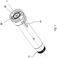
- FIG. 1 is a perspective view of exemplary components of such a container holder assembly.
- a tubular body 10 such as a container holder, is elongated along an axis X with a closed proximal end and an open distal end for receiving a container 20.
- a retaining member 30 is arranged to the container holder for gripping the container and resiliently urging it into abutment with a stop surface inside the tubular body 20.
- Fig.1 shows the retaining member 30 arranged at the open, distal end of the tubular body 10, gripping the distal end of the container 20.
- the invention is not restricted to this arrangement however.
- the container holder assembly may be may be constructed in many different ways without departing from the concept of the present invention.
- the resilient structure of the retaining member 30 will be explained below.
- the tubular body 10 may also be arranged with radially protruding elements 16 arranged to key the container holder assembly to a certain type of delivery device in order to prevent the use of the assembly in a device that it is not intended for.
- a proximal part of the tubular body 10 may be arranged with an interface 12, such as threads, for connecting a delivery member (not shown).
- the delivery member may be a needle, a nozzle, a mouth piece, or the like.
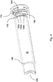
- Fig. 2 shows the assembly in a semi-assembled state, wherein the container 20 has not yet been loaded in the tubular body 10 and wherein the retaining member 30 is loosely arranged to the tubular body 10, prepared for receiving the container 20.
- the physical dimensions of the assembly are adapted to a certain type of container but the present invention allows for large dimensional tolerances of the containers thanks to the resilient structure of the retaining member 30, which holds the container in a predetermined position inside the container holder despite variations in physical dimensions of the container.
- An exemplary container 20, as show in Fig. 2 may contain medicament and is tubular and made of glass.
- a proximal end typically has a shoulder portion 26 connecting the tubular part with a neck portion and a cap 24.
- the cap comprises a septum that seals the proximal end of the container.
- the distal end of the container is sealed by an axially movable stopper 22.
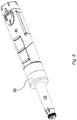
- Fig. 3 depicts an embodiment of the invention.
- the retaining member 30, which is here shown outside the tubular body 10, comprises a resilient structure that allows the body of the retaining member to be flexible in the axial direction, i.e. to stretch or to compress, so that the proximal end and the distal end of the retaining member may be axially displaced with regard to each other.
- the resilient structure 36 is achieved by forming circumferentially elongated cut-outs, or slits, in the tubular wall of the retaining member 30.
- the slits are arranged in at least two parallel circumferentially aligned rows, wherein a space between any two slits of one row is aligned with the centre of a slit of an adjacent row.
- At least two gripping means 34 are arranged on the distal annular end surface of the retaining member 30.
- the gripping means 34 may be formed as distally protruding, inwardly curved hooks that are able to flex radially outwards as the container 20 is pushed inside the tubular body 10.
- Each gripping means is aligned with the centre of one of the most distal slits.
- the proximal portion of the retaining member 30 is arranged with a first locking means 32 capable of mutual mechanical connection with a second locking means 120 of the tubular body 10.
- the first locking means 32 may be formed as at least two protrusions, or guide knobs, that extend radially outwardly from the outer circumferential surface of the retaining member 30, whereas the second locking means 120 may be formed as a cut-out, or guide track, that is able to guide a protrusion of the first locking means 32 along the track as the first and second locking means are axially rotated in relation to each other, i.e. in the fashion of a bayonet connection.
- Each protrusion is aligned with the centre of one of the most proximal slits.
- the gripping means 34 are arranged to abut the distal annual end surface of the container 20 when the container has been placed in the tubular body 10 and the first and second locking means are brought into locking position with each other (explained in detail below).
- the resiliency of the retaining member 30 of the exemplary embodiment of Fig. 3 results from the careful alignment of the slits, the gripping means 34 and the first locking means 32.
- the number of gripping means equals the number of slits in the most distal row of slits and the number of first locking means equals the number of slits in the most proximal row of slits.
- the number of slits in one row equals the number of slits in each of the other rows.
- the number of slits in one row equals two.
- the circumferential length occupied by a slit is significantly larger than the circumferential length occupied by the space between two slits of any adjacent rows.
- an end - preferably the distal end - of the tubular body 10 may be arranged with a second resilient structure 110.
- the container holder assembly with a container inside, is inserted by a user in a delivery device by attaching the tubular body to holding means (not shown) arranged at a proximal receiving end of the device (not shown).
- the distal annular end surface of the tubular body thereby comes into abutment with a surface of the delivery device, forcing the second resilient structure 110 to compress axially.
- the user may then attach a delivery member to the interface 12 in order to use the device
- Fig. 4 shows a cross-section of the exemplary embodiment of the tubular body 10.
- the second locking means 120 ( Fig. 2 ) may be formed as a cut-out, or guide track, that is able to guide a protrusion of the first locking means 32 along the track as the first and second locking means are axially rotated in relation to each other.
- the track has a distally directed opening 170 through which the first locking means 32 of the retaining member 30 may be inserted into the track. After insertion the first locking means is in the initial position 140 of the second locking means.
- the first locking means is forced past a first stopper 130a arranged to prevent unintentional rotation of the locking means.
- the first locking means is then in a loading position 150, as depicted in Fig. 2 .
- the container holder assembly is ready for insertion of a container 20 into the tubular body 10.
- the gripping means 34 flex radially outwards, snapping back as the distal end of the container passes the gripping means.
- the container is now loosely secured in the tubular body, resting with its shoulder portion 26 against the inner annular ledge 190 of the tubular body 10.
- the container will not fall out since the gripping means 34 is blocking movement in the distal direction and the first locking means 32 is confined between the first stopper 130a and a second stopper 130b. However, in the loading position, the retaining member still does not exert an axial force on the container.
- an axial force needs to be exerted between the tubular body and the container, such that they are pressed towards each other.
- this is attained by further rotation of the retaining member with regard to the tubular body.
- the gripping means 34 is arranged to abut the distal annular surface of the container 20 and the container is hindered from proximal displacement because it is resting with its shoulder portion 26 in abutment with the inner annular ledge 190 of the tubular body 10, the resilient structure 36 begins to stretch axially in the proximal direction.
- the tensioned resilient structure exerts an axial force such that the gripping means 34 urges the shoulder portion 26 of the container 20 and the inner annular ledge 190 of the tubular body 10 against each other.
- the track of the second locking means 120 eventually returns to a circumferentially aligned path.
- the first locking means is forced past the third stopper 130c and comes to rest in a holding position 160, abutting the distal surface of the track due to the axial force exerted by the resilient structure 36.
- the overall pitch of the track of the second locking means is carefully determined during manufacture of the assembly to achieve a force that is strong enough to fix the container inside the tubular body, regardless of the tolerances of the container used, but at the same time to achieve a force that is not so strong as to risk damaging the container.
- Another parameter that may be used to calibrate the force during manufacturing is the resiliency of the resilient structure 36. This may be varied, for instance by selecting an appropriate number of rows of slits of the resilient structure, or by the material chosen for the container holder assembly, or by the thickness of the wall of the retaining member or the distance between the rows of slits, etc.
- FIG. 5 is a perspective view of a medicament delivery device 40 to which a container holder 10', comprising a container (not shown), has been attached using retaining member 50.
- Fig. 6 shows a cross-section of the connection between the device 40 and the container holder 10' of Fig. 5 .
- the retaining member 50 is, in the exemplary embodiment shown, comprised of a first part 50a, a second part 50b and a third part 50c that together form an axially aligned annular housing with a through-going axially aligned hole for accommodating the container holder 10' with the container 20.
- the retaining member 50 also houses a resilient structure 500 comprising at least one resilient washer 56, and a spacer 52. If multiple resilient washers are used, at least one supporting washer 54 is positioned between them in order to separate the resilient washers from each other.
- the third part 50c of the retaining member comprises attachment means (not shown) on a distal circumferential surface for mutually connecting with engagement means 44 on a proximal circumferential surface of the delivery device 40.
- attachment means not shown
- engagement means 44 on a proximal circumferential surface of the delivery device 40.
- Various solutions are conceivable for the mutual connection of the retaining member and the delivery device, e.g. such as a threaded connection or bayonet connection.
- the retaining member 50 and its constituent components are assembled during manufacturing and are designed for a predetermined kind of container holder 10', which in turn is designed to hold a predetermined kind of container 20.
- the object of the invention is to allow large tolerances in the physical dimensions of the container 20 without affecting the accuracy of the dose delivery, i.e. by holding the container in a fixed position in relation to the container holder, and without damaging the container. This is achieved by resilient fixation of the container in the holder.
- Fig. 7 is an exploded view of the delivery device 40 and the container holder assembly, i.e. the retaining member 50 and the container holder 10'. Also shown is an inserted exploded image of the resilient structure 500 housed in the resilient means 50.
- the resiliency of the retaining member 50 is a function of the stack of resilient washers 56.
- the washers may, for instance, have a wavy shape that results in an axial restoring force if the washers are compressed. Since the shape of the individual resilient washers is identical a supporting washer 54 may be used to separate them from each other. Otherwise, adjacently packed resilient washers would result in much reduced flexibility.
- a container When the delivery device is to be used a container is inserted in the tubular body 10' by the distal end. At least two radially inwardly protruding cut-outs in the form of flexible tongues 195 are arranged in the circumferential wall of the tubular body 10' to flex radially outwards as the cap 24 is pushed against the tongues in order to let the container pass. Thereafter, the tongues flex back inwards, preventing return-movement of the container and securing it by its neck portion 28 ( Fig. 6 ) inside the tubular body 10' such that it cannot accidentally fall out before the container holder assembly has been attached to the delivery device 40. When the container is secured in the tubular body, the distal end of the container still protrudes distally of the tubular body, the function of which will be explained below.
- the tubular body 10' holding the container is then inserted in the retaining member 50 from the distal side such that the proximal surface of the circumferential flange 14' arranged at the distal end of the tubular body comes to rest against the distal surface of the annular spacer 52.
- the container holder assembly, including the container, is subsequently attached to the proximal end of the delivery device by the mutual connection described above.
- the protruding distal annular surface of the container abuts the stopping element 42.
- the abutting function of the stopping element could also be achieved by an integrated surface of the delivery member 40 itself, such as a surface of the housing.
Landscapes
- Health & Medical Sciences (AREA)
- Veterinary Medicine (AREA)
- Life Sciences & Earth Sciences (AREA)
- Animal Behavior & Ethology (AREA)
- General Health & Medical Sciences (AREA)
- Public Health (AREA)
- Engineering & Computer Science (AREA)
- Vascular Medicine (AREA)
- Anesthesiology (AREA)
- Biomedical Technology (AREA)
- Heart & Thoracic Surgery (AREA)
- Hematology (AREA)
- Pharmacology & Pharmacy (AREA)
- Infusion, Injection, And Reservoir Apparatuses (AREA)
- Details Of Rigid Or Semi-Rigid Containers (AREA)
- Medical Preparation Storing Or Oral Administration Devices (AREA)
Description
- The present invention relates to a cartridge assembly for medicament delivery devices and in particular to a cartridge assembly where safety and handling aspects have been improved by the interaction of a cartridge, a cartridge holder and a cartridge retainer.
- A medicament delivery device, such as an injector, is often arranged with a container holder to allow operations to be carried out on the container, for instance displacement within the injector housing during skin penetration, expulsion of medicament by a plunger acting on the stopper in the container, penetration of the septum using a needle and replacement of container. Because of tolerances, manufactured containers vary in size, which may result in the position of the container within the holder being somewhat affected during handling of the device. For instance, displacement of the container may occur as a result of penetrating the septum of the container with a needle or by sudden impact forces to the housing of the device. If the container is not exactly positioned in relation to the holder, the stroke length of the plunger rod - and consequently the dosage set by the user or the manufacturer of the device - will not be exactly correlated to the actual position of the container, resulting in the wrong dose being delivered. Also, movement of the container within the holder may lead to a higher risk of breaking the container due to impact forces between the holder and the container.
- A number of prior art solutions to container holders are known:
US 2007/0021718 A1 describes a spring for use as a supporting device between a container and a housing in order to firmly position the container within the housing. The spring is not attached to the container holder but wedged between an insert and the container, or attached to the housing of a power pack. Therefore it is not suited to secure the container to the container holder on its own. -
EP 0 941 133 B1 discloses a cartridge assembly intended to key a cartridge to a certain type of injection pen in order to prevent cross-use of different cartridges and pens, which could result in the wrong drug being used or the patient receiving the wrong dose. Various embodiments describe a cartridge assembly where the cartridge is secured in a cartridge holder that is adapted for a specific cartridge and for a specific pen. Also, the rigid construction using cooperating threaded holder parts to secure the cartridge could lead to damage to the cartridge if too much force is used to join the parts. -
WO 2010/097116 A1 describes a container holder for securely holding a container wherein the holder includes a support for the shoulder of the container in the front end, flexible arms exert a compressive radial force on the sides of the container and hooks at the rear end keep the container inside the container once it has been inserted in the container holder and pushed past the hooks. There is no resilient member that holds the container in the same position in relation to the holder, i.e. due to tolerances the container may be slightly axially displaced during handling of the device. -
US 2006/0030819 A1 discloses a cartridge container arranged with inwardly directed resilient tabs that apply a radial compressive force on the cartridge to align and to hold it in proper orientation and to hinder axial and radial movement of the cartridge inside the cartridge container during loading. The use of resilient tabs allows accommodation of cartridges of different sizes, but no compressive force is used to bias the cartridge axially. -
EP 2 021 054 B1 describes an injection device wherein a syringe may be moved from a retracted position to an extended position for discharging its contents and wherein the syringe is held by a syringe carrier. The syringe is held in the carrier by arms arranged with lugs and dampers that grip the rear surface of a flange of the syringe in order to minimize the risk of the syringe breaking by impact force such as caused by sudden movement, i.e. during extension or retraction of the syringe. No precaution is taken to fix the syringe in a predetermined position inside the carrier. -
US2068927 discloses a resilient element that axially biases the container against a syringe element which is located outside of the container holder. - Therefore, there is a need for a device that can securely keep the container in one predetermined position in relation to the container holder in order to be able to deliver a set dose in a safe and reliable way without damaging the holder. With regard to cost and complexity the device needs to be easy to manufacture and to implement in existing devices. The resulting device must also be simple and intuitive for the end user to operate.
- The invention is defined according to claim 1.
- According to a final aspect of the invention the container holder assembly is to be used in a medicament delivery device.
- There are a number of advantages with the present invention. The use of a resilient structure in a retaining member allows a container to be fixed within a holder, regardless of size differences of different containers, such as arising from tolerances, since the resilient structure adapts its size to the size of the container. The container may otherwise be accidentally displaced during handling and during attachment of a delivery member. When the container is fixed within the holder the stroke length of a plunger of a delivery device may be accurately determined so that precise doses can be delivered.
- Another advantage of the structure of the retaining member is the resiliency that permits a softer tensioning of the grip on the container as compared to the grip exerted by a rigid retainer. This helps to prevent damage to the container caused by careless tensioning of the container holder/retainer. It also protects the container from otherwise damaging impacts that may occur during handling of the device.
- Yet another advantage of a retainer is that it prevents the container from accidentally falling out of the container holder during handling before it is attached to a delivery device. It is also relatively protected within the container holder as compared to outside the holder.
- Also, since the assembly is delivered to the user in a semi-assembled state it is easy for the user to insert a container and arrange the container holder assembly to a delivery device to administer medicament.
- These and other aspects and advantages of the present invention will become apparent from the following detailed description and from the accompanying drawings.
- In the following description of embodiments of the invention, reference will be made to the accompanying drawings of which:
- Fig. 1
- is a perspective view of a first embodiment of the present invention in an assembled position.
- Fig. 2
- is a perspective view of a first embodiment of the present invention showing a container outside the container holder assembly.
- Fig. 3
- is a perspective view of a first embodiment of the present invention showing the container holder assembly in a disassembled position.
- Fig. 4
- is a cross-sectional view of a first embodiment of the present invention showing the inside of the container holder.
- Fig. 5
- is a perspective view of a second embodiment of the invention.
- Fig. 6
- is a cross-sectional view of a second embodiment of the invention.
- Fig. 7
- is an exploded perspective view of a second embodiment of the invention.
- Embodiments of the present invention will now be described in detail. As should be noted in the present application, when the term "distal part/end" is used, this refers to the part/end of the delivery device, or the parts/ends of the members thereof, which is/are located the furthest away from the medicament delivery site of the patient. Correspondingly, when the term "proximal part/end" is used, this refers to the part/end of the delivery device, or the parts/ends of the members thereof, which, is/are located closest to the medicament delivery site of the patient.
- According to a main aspect of the invention it relates to a container holder assembly for use in a medicament delivery device, which container holder assembly comprises a tubular body elongated in an axial direction, said tubular body having a proximal end and an opposite distal end A retaining member is releasably arranged to said tubular body for securing an elongated container placed inside the tubular body. The retaining member comprises a resilient structure that is capable of exerting an axial force on said container in said tubular body for holding the container in a fixed position inside the tubular body and thereby avoiding breakage or displacement of the container.
- An exemplary embodiment of the present invention is shown in the
figures 1-4 . The embodiment shown in the figures is a container holder assembly for medicament delivery devices but is not restricted to it.Fig. 1 is a perspective view of exemplary components of such a container holder assembly. Atubular body 10, such as a container holder, is elongated along an axis X with a closed proximal end and an open distal end for receiving acontainer 20. In order to secure thecontainer 20 inside thetubular body 10, a retainingmember 30 is arranged to the container holder for gripping the container and resiliently urging it into abutment with a stop surface inside thetubular body 20. - The exemplary embodiment disclosed in
Fig.1 shows the retainingmember 30 arranged at the open, distal end of thetubular body 10, gripping the distal end of thecontainer 20. The invention is not restricted to this arrangement however. The container holder assembly may be may be constructed in many different ways without departing from the concept of the present invention. The resilient structure of the retainingmember 30 will be explained below. - The
tubular body 10 may also be arranged with radially protrudingelements 16 arranged to key the container holder assembly to a certain type of delivery device in order to prevent the use of the assembly in a device that it is not intended for. - A proximal part of the
tubular body 10 may be arranged with aninterface 12, such as threads, for connecting a delivery member (not shown). The delivery member may be a needle, a nozzle, a mouth piece, or the like. -
Fig. 2 shows the assembly in a semi-assembled state, wherein thecontainer 20 has not yet been loaded in thetubular body 10 and wherein the retainingmember 30 is loosely arranged to thetubular body 10, prepared for receiving thecontainer 20. The physical dimensions of the assembly are adapted to a certain type of container but the present invention allows for large dimensional tolerances of the containers thanks to the resilient structure of the retainingmember 30, which holds the container in a predetermined position inside the container holder despite variations in physical dimensions of the container. - An
exemplary container 20, as show inFig. 2 , may contain medicament and is tubular and made of glass. A proximal end typically has ashoulder portion 26 connecting the tubular part with a neck portion and acap 24. The cap comprises a septum that seals the proximal end of the container. The distal end of the container is sealed by an axiallymovable stopper 22. -
Fig. 3 depicts an embodiment of the invention. The retainingmember 30, which is here shown outside thetubular body 10, comprises a resilient structure that allows the body of the retaining member to be flexible in the axial direction, i.e. to stretch or to compress, so that the proximal end and the distal end of the retaining member may be axially displaced with regard to each other. Theresilient structure 36 is achieved by forming circumferentially elongated cut-outs, or slits, in the tubular wall of the retainingmember 30. The slits are arranged in at least two parallel circumferentially aligned rows, wherein a space between any two slits of one row is aligned with the centre of a slit of an adjacent row. - At least two
gripping means 34 are arranged on the distal annular end surface of the retainingmember 30. The gripping means 34 may be formed as distally protruding, inwardly curved hooks that are able to flex radially outwards as thecontainer 20 is pushed inside thetubular body 10. Each gripping means is aligned with the centre of one of the most distal slits. - The proximal portion of the retaining
member 30 is arranged with a first locking means 32 capable of mutual mechanical connection with a second locking means 120 of thetubular body 10. The first locking means 32 may be formed as at least two protrusions, or guide knobs, that extend radially outwardly from the outer circumferential surface of the retainingmember 30, whereas the second locking means 120 may be formed as a cut-out, or guide track, that is able to guide a protrusion of the first locking means 32 along the track as the first and second locking means are axially rotated in relation to each other, i.e. in the fashion of a bayonet connection. Each protrusion is aligned with the centre of one of the most proximal slits. - The gripping means 34 are arranged to abut the distal annual end surface of the
container 20 when the container has been placed in thetubular body 10 and the first and second locking means are brought into locking position with each other (explained in detail below). - The resiliency of the retaining
member 30 of the exemplary embodiment ofFig. 3 results from the careful alignment of the slits, the grippingmeans 34 and the first locking means 32. For best performance, the number of gripping means equals the number of slits in the most distal row of slits and the number of first locking means equals the number of slits in the most proximal row of slits. Preferably, the number of slits in one row equals the number of slits in each of the other rows. Most preferably, the number of slits in one row equals two. To achieve good resiliency it is also preferable that the circumferential length occupied by a slit is significantly larger than the circumferential length occupied by the space between two slits of any adjacent rows. - In a similar fashion, an end - preferably the distal end - of the
tubular body 10 may be arranged with a secondresilient structure 110. As the container holder assembly, with a container inside, is inserted by a user in a delivery device by attaching the tubular body to holding means (not shown) arranged at a proximal receiving end of the device (not shown). The distal annular end surface of the tubular body thereby comes into abutment with a surface of the delivery device, forcing the secondresilient structure 110 to compress axially. The user may then attach a delivery member to theinterface 12 in order to use the device -
Fig. 4 shows a cross-section of the exemplary embodiment of thetubular body 10. The second locking means 120 (Fig. 2 ) may be formed as a cut-out, or guide track, that is able to guide a protrusion of the first locking means 32 along the track as the first and second locking means are axially rotated in relation to each other. The track has a distally directedopening 170 through which the first locking means 32 of the retainingmember 30 may be inserted into the track. After insertion the first locking means is in theinitial position 140 of the second locking means. By slightly rotating thetubular body 10 and the retainingmember 30 with respect to each other, for instance by using a specialized tool, the first locking means is forced past afirst stopper 130a arranged to prevent unintentional rotation of the locking means. The first locking means is then in aloading position 150, as depicted inFig. 2 . In theloading position 150 the container holder assembly is ready for insertion of acontainer 20 into thetubular body 10. As the container is pushed into the tubular body the gripping means 34 flex radially outwards, snapping back as the distal end of the container passes the gripping means. The container is now loosely secured in the tubular body, resting with itsshoulder portion 26 against the innerannular ledge 190 of thetubular body 10. The container will not fall out since the grippingmeans 34 is blocking movement in the distal direction and the first locking means 32 is confined between thefirst stopper 130a and asecond stopper 130b. However, in the loading position, the retaining member still does not exert an axial force on the container. - To achieve the object of the invention, i.e. to fix the container in an exact predetermined position in the
tubular body 10, an axial force needs to be exerted between the tubular body and the container, such that they are pressed towards each other. In the exemplary embodiment ofFig. 4 this is attained by further rotation of the retaining member with regard to the tubular body. When the first locking means 32 is forced past thesecond stopper 130b the track of the second locking means deviates from a circumferential path to a circumferential/axial path, forcing the proximal part, i.e. the first locking means and consequently the whole the retaining member in a proximal, axial direction. Since the grippingmeans 34 is arranged to abut the distal annular surface of thecontainer 20 and the container is hindered from proximal displacement because it is resting with itsshoulder portion 26 in abutment with the innerannular ledge 190 of thetubular body 10, theresilient structure 36 begins to stretch axially in the proximal direction. The tensioned resilient structure exerts an axial force such that the grippingmeans 34 urges theshoulder portion 26 of thecontainer 20 and the innerannular ledge 190 of thetubular body 10 against each other. - As the retaining member and the tubular body are further rotated with regard to each other, the track of the second locking means 120 eventually returns to a circumferentially aligned path. The first locking means is forced past the
third stopper 130c and comes to rest in aholding position 160, abutting the distal surface of the track due to the axial force exerted by theresilient structure 36. - The overall pitch of the track of the second locking means is carefully determined during manufacture of the assembly to achieve a force that is strong enough to fix the container inside the tubular body, regardless of the tolerances of the container used, but at the same time to achieve a force that is not so strong as to risk damaging the container.
- Another parameter that may be used to calibrate the force during manufacturing is the resiliency of the
resilient structure 36. This may be varied, for instance by selecting an appropriate number of rows of slits of the resilient structure, or by the material chosen for the container holder assembly, or by the thickness of the wall of the retaining member or the distance between the rows of slits, etc. - Other designs of the locking means 32, 120 are also conceivable, such as mutually engaging threads.
- A second exemplary embodiment of the present invention is shown in
Figs. 5-7 .Fig. 5 is a perspective view of amedicament delivery device 40 to which a container holder 10', comprising a container (not shown), has been attached using retainingmember 50. -
Fig. 6 shows a cross-section of the connection between thedevice 40 and the container holder 10' ofFig. 5 . The retainingmember 50 is, in the exemplary embodiment shown, comprised of afirst part 50a, asecond part 50b and athird part 50c that together form an axially aligned annular housing with a through-going axially aligned hole for accommodating the container holder 10' with thecontainer 20. The retainingmember 50 also houses aresilient structure 500 comprising at least oneresilient washer 56, and aspacer 52. If multiple resilient washers are used, at least one supportingwasher 54 is positioned between them in order to separate the resilient washers from each other. - The
third part 50c of the retaining member comprises attachment means (not shown) on a distal circumferential surface for mutually connecting with engagement means 44 on a proximal circumferential surface of thedelivery device 40. Various solutions are conceivable for the mutual connection of the retaining member and the delivery device, e.g. such as a threaded connection or bayonet connection. - The retaining
member 50 and its constituent components are assembled during manufacturing and are designed for a predetermined kind of container holder 10', which in turn is designed to hold a predetermined kind ofcontainer 20. The object of the invention, however, is to allow large tolerances in the physical dimensions of thecontainer 20 without affecting the accuracy of the dose delivery, i.e. by holding the container in a fixed position in relation to the container holder, and without damaging the container. This is achieved by resilient fixation of the container in the holder. - The function of the retaining
member 50 will now be described in conjunction withFig. 7 , which is an exploded view of thedelivery device 40 and the container holder assembly, i.e. the retainingmember 50 and the container holder 10'. Also shown is an inserted exploded image of theresilient structure 500 housed in theresilient means 50. - The resiliency of the retaining
member 50 is a function of the stack ofresilient washers 56. The washers may, for instance, have a wavy shape that results in an axial restoring force if the washers are compressed. Since the shape of the individual resilient washers is identical a supportingwasher 54 may be used to separate them from each other. Otherwise, adjacently packed resilient washers would result in much reduced flexibility. - When the delivery device is to be used a container is inserted in the tubular body 10' by the distal end. At least two radially inwardly protruding cut-outs in the form of
flexible tongues 195 are arranged in the circumferential wall of the tubular body 10' to flex radially outwards as thecap 24 is pushed against the tongues in order to let the container pass. Thereafter, the tongues flex back inwards, preventing return-movement of the container and securing it by its neck portion 28 (Fig. 6 ) inside the tubular body 10' such that it cannot accidentally fall out before the container holder assembly has been attached to thedelivery device 40. When the container is secured in the tubular body, the distal end of the container still protrudes distally of the tubular body, the function of which will be explained below. - The tubular body 10' holding the container is then inserted in the retaining
member 50 from the distal side such that the proximal surface of the circumferential flange 14' arranged at the distal end of the tubular body comes to rest against the distal surface of theannular spacer 52. The container holder assembly, including the container, is subsequently attached to the proximal end of the delivery device by the mutual connection described above. - As the mutual connection of the container holder assembly and the delivery device is tightened, such as by turning the retaining
member 50 in relation to thedelivery device 40 for mutually engaging threads or for operating a bayonet connection, the protruding distal annular surface of the container abuts the stoppingelement 42. The abutting function of the stopping element could also be achieved by an integrated surface of thedelivery member 40 itself, such as a surface of the housing. - Further tightening of the connection results in compression of the
resilient washers 56 between thefirst part 50a and thespacer 52 resting against the flange 14'. This leads to a restoring axial force, arising from the compressedresilient washers 56, that acts on the flange 14' to urge the tubular body 10' in the distal direction. Since thecontainer 20 abuts the stoppingelement 42, the inner annular ledge 190' is brought into abutment with theshoulder portion 26 of the container, forcing the container against the stoppingelement 42. The force arising from the compression of theresilient washers 56 thereby fixes the container with regard to the tubular body 10' and thedelivery device 40.
Claims (2)
- Container holder assembly for use in a medicament delivery device, comprising- a tubular body (10') elongated in an axial direction, said tubular body having a proximal end and an opposite distal end, and- a retaining member (50) releasably arranged to said tubular body for securing an elongated container (20) placed inside the tubular body,- said retaining member (50) comprising a resilient structure (500) capable of exerting an axial force on said container (20) in said tubular body (10') for holding the container in a fixed position inside the tubular body and thereby avoiding breakage or displacement of the container,- a distal end of said container protruding from a distal end of said tubular body andcharacterised in that the retaining member (50) further comprises an annular housing arranged to accommodate said resilient structure (500) and wherein said annular housing comprises attachment means for releasibly attaching to a proximal end of a medicament delivery device such that the distal end of said container (20) is resiliently pressed against a stopping element (42) of said delivery device, wherein the container (20) comprises a shoulder portion (26) abutting a proximal inner annular ledge (190') of the tubular body (10'), and wherein the resilient structure (500) comprises at least one resilient washer (56) and an annular spacer (52), and wherein said retaining member (50) is capable of accommodating said tubular body (10') such that a distal surface of the annular spacer (52) abuts a circumferential flange (14') of the tubular body, and wherein the container (20) abuts the stopping element (42), the inner annular ledge (190') is brought into abutment with the shoulder portion (26) of the container, forcing the container against the stopping element (42).
- Medicament delivery device comprising a container holder assembly according to claim 1.
Applications Claiming Priority (3)
| Application Number | Priority Date | Filing Date | Title |
|---|---|---|---|
| US41102010P | 2010-11-08 | 2010-11-08 | |
| SE1051160 | 2010-11-08 | ||
| PCT/SE2011/051321 WO2012064259A1 (en) | 2010-11-08 | 2011-11-07 | Container holder assembly |
Publications (3)
| Publication Number | Publication Date |
|---|---|
| EP2637720A1 EP2637720A1 (en) | 2013-09-18 |
| EP2637720A4 EP2637720A4 (en) | 2018-01-17 |
| EP2637720B1 true EP2637720B1 (en) | 2020-06-17 |
Family
ID=46051195
Family Applications (2)
| Application Number | Title | Priority Date | Filing Date |
|---|---|---|---|
| EP11840292.4A Active EP2637721B1 (en) | 2010-11-08 | 2011-11-07 | Container holder assembly |
| EP11839466.7A Active EP2637720B1 (en) | 2010-11-08 | 2011-11-07 | Container holder assembly |
Family Applications Before (1)
| Application Number | Title | Priority Date | Filing Date |
|---|---|---|---|
| EP11840292.4A Active EP2637721B1 (en) | 2010-11-08 | 2011-11-07 | Container holder assembly |
Country Status (7)
| Country | Link |
|---|---|
| US (4) | US9861753B2 (en) |
| EP (2) | EP2637721B1 (en) |
| JP (2) | JP5688471B2 (en) |
| CN (2) | CN103167888B (en) |
| AU (2) | AU2011326864B2 (en) |
| TW (2) | TWI464002B (en) |
| WO (2) | WO2012064258A1 (en) |
Families Citing this family (61)
| Publication number | Priority date | Publication date | Assignee | Title |
|---|---|---|---|---|
| PL2240222T3 (en) | 2008-01-11 | 2018-08-31 | Ucb Biopharma Sprl | Systems for administering medication for rheumatoid arthritis patients |
| US8052645B2 (en) | 2008-07-23 | 2011-11-08 | Avant Medical Corp. | System and method for an injection using a syringe needle |
| EP2276527B1 (en) | 2008-05-20 | 2018-02-28 | Avant Medical Corp. | Autoinjector system |
| TWI464002B (en) | 2010-11-08 | 2014-12-11 | Shl Group Ab | Container holder assembly and medicament delivery device assembly |
| LT2699293T (en) | 2011-04-20 | 2019-04-25 | Amgen Inc. | Autoinjector apparatus |
| WO2012164404A2 (en) | 2011-06-02 | 2012-12-06 | Ucb Pharma S.A. | Auto-injector |
| EP2601992A1 (en) | 2011-12-08 | 2013-06-12 | Sanofi-Aventis Deutschland GmbH | Syringe carrier |
| EP2806922B1 (en) * | 2012-01-25 | 2018-09-19 | Novo Nordisk A/S | Drug delivery device with cartridge fixation feature |
| AU2013224350A1 (en) | 2012-02-24 | 2014-08-21 | Novo Nordisk A/S | Drug delivery device with cartridge snap holding feature |
| AU2013248417B2 (en) * | 2012-04-18 | 2015-12-10 | Carebay Europe Ltd | Medicament delivery device |
| USD898908S1 (en) | 2012-04-20 | 2020-10-13 | Amgen Inc. | Pharmaceutical product cassette for an injection device |
| EP2854906A1 (en) * | 2012-05-29 | 2015-04-08 | Carebay Europe Limited | Medicament container retaining mechanism |
| EP2879736B1 (en) * | 2012-07-30 | 2018-11-14 | UCB Biopharma SPRL | Auto-injector |
| USD726902S1 (en) | 2012-07-30 | 2015-04-14 | Ucb Pharma S.A. | Cassette device for administering medication |
| WO2014019997A1 (en) | 2012-07-30 | 2014-02-06 | Ucb Pharma S.A. | Auto-injector |
| EP2879738B1 (en) | 2012-07-30 | 2019-09-11 | UCB Biopharma SPRL | Auto-injector |
| EP2879737B1 (en) | 2012-07-30 | 2018-09-12 | UCB Biopharma SPRL | Auto-injector |
| JP2015226555A (en) * | 2012-09-25 | 2015-12-17 | パナソニック株式会社 | Syringe unit and drug injection device to which it is attached |
| EP2777684A1 (en) * | 2013-03-14 | 2014-09-17 | Sanofi-Aventis Deutschland GmbH | Medicament container carrier and adapter |
| JP6768501B2 (en) | 2013-03-15 | 2020-10-14 | アムゲン・インコーポレーテッド | Drug cassettes, automatic injection machines, and automatic injection machine systems |
| DE102013007389A1 (en) * | 2013-04-30 | 2014-10-30 | Britannia Pharmaceuticals Ltd. | Drug delivery device |
| GB201313888D0 (en) * | 2013-08-02 | 2013-09-18 | Consort Medical Plc | Assembly for an autoinjector device |
| MX370024B (en) * | 2013-08-29 | 2019-11-28 | Sanofi Sa | Safety device for a medicament container. |
| WO2015110529A1 (en) | 2014-01-27 | 2015-07-30 | Ucb Biopharma Sprl | Auto-injector |
| WO2015110532A1 (en) | 2014-01-27 | 2015-07-30 | Ucb Biopharma Sprl | Auto-injector |
| EP3099351B1 (en) | 2014-01-27 | 2019-11-06 | UCB Biopharma SPRL | Auto-injector |
| GB201416985D0 (en) | 2014-09-26 | 2014-11-12 | Ucb Biopharma Sprl And Bespak Europ Ltd | Housing part for an auto-injector |
| JP6254714B2 (en) * | 2014-09-30 | 2017-12-27 | パナソニックヘルスケア株式会社 | Drug cartridge holding unit and drug injection device including the same |
| US10675415B2 (en) | 2014-09-30 | 2020-06-09 | Phc Holdings Corporation | Pharmaceutical syringe unit, pharmaceutical injection device equipped with said unit, injection needle attachment and removal fixture, and storage case |
| CN107106776B (en) * | 2014-10-09 | 2020-05-22 | 赛诺菲 | Housing and drug delivery device with a housing |
| FR3036968A1 (en) * | 2015-06-02 | 2016-12-09 | Biocorp Prod | BOX FOR MOUNTING A CONTAINER ON AN INJECTOR PEN, AN INJECTABLE PRODUCT TANK ASSEMBLY FOR AN INJECTOR PEN AND AN INJECTOR PEN EQUIPPED WITH SUCH AN ASSEMBLY |
| TW201703802A (en) | 2015-06-03 | 2017-02-01 | 賽諾菲阿凡提斯德意志有限公司 | Syringe support and autoinjector |
| TW201705994A (en) | 2015-06-03 | 2017-02-16 | 賽諾菲阿凡提斯德意志有限公司 | Autoinjector and method of assembling |
| TW201700117A (en) | 2015-06-03 | 2017-01-01 | 賽諾菲阿凡提斯德意志有限公司 | Syringe bracket and assembly method for autoinjector |
| US11207465B2 (en) | 2015-06-04 | 2021-12-28 | West Pharma. Services Il. Ltd. | Cartridge insertion for drug delivery device |
| WO2017102175A1 (en) | 2015-12-14 | 2017-06-22 | Carebay Europe Ltd | Medicament delivery device |
| WO2017188427A1 (en) * | 2016-04-28 | 2017-11-02 | 株式会社大協精工 | Container |
| US10898646B2 (en) * | 2016-04-29 | 2021-01-26 | Shl Medical Ag | Container holder assembly |
| US11278672B2 (en) * | 2016-07-06 | 2022-03-22 | Shl Medical Ag | Device for a medicament container |
| USD799204S1 (en) * | 2016-07-12 | 2017-10-10 | Acme United Corporation | Tool holder assembly |
| US20180014996A1 (en) * | 2016-07-12 | 2018-01-18 | Hba Medical Group, Inc. | Self sheathing anesthetic needle with a dedicated syringe |
| CA3030336C (en) | 2016-07-22 | 2020-11-17 | Shl Medical Ag | Medicament container holder for a medicament delivery device and method of assemblying a medicament delivery device |
| KR101911319B1 (en) * | 2017-01-06 | 2018-10-24 | 김성욱 | Medicine injection device |
| CN113855913A (en) | 2017-05-30 | 2021-12-31 | 西部制药服务有限公司(以色列) | Modular drive mechanism for a wearable injector |
| CN111683703B (en) * | 2017-12-22 | 2022-11-18 | 西氏医药包装(以色列)有限公司 | Syringe adapted for cartridges of different sizes |
| EP3773811A1 (en) * | 2018-03-26 | 2021-02-17 | SHL Medical AG | Medicament container holder |
| EP3597240A1 (en) * | 2018-07-18 | 2020-01-22 | Sanofi | Cartridge unit for a drug delivery device |
| EP3597238A1 (en) | 2018-07-18 | 2020-01-22 | Sanofi | Cartridge assembly and method for assembling the same |
| EP3597236A1 (en) * | 2018-07-18 | 2020-01-22 | Sanofi | Cartridge assembly for a drug delivery device and method for assembling the same |
| EP3597237A1 (en) * | 2018-07-18 | 2020-01-22 | Sanofi | Cartridge assembly for a drug delivery device and drug delivery device |
| EP3597233A1 (en) | 2018-07-18 | 2020-01-22 | Sanofi | Drug delivery devices |
| FR3086177B1 (en) * | 2018-09-20 | 2022-11-04 | Aptar France Sas | AUTOINJECTOR. |
| US11882824B2 (en) | 2019-03-08 | 2024-01-30 | Fisher Bioservices Inc. | Cryogenic vial sleeve and related systems and methods |
| US11358227B2 (en) * | 2019-06-07 | 2022-06-14 | Kennametal Inc. | Toolholder assembly with flexible canister |
| US20210197354A1 (en) * | 2019-12-26 | 2021-07-01 | Wolf Tooth Components, LLC | Multi-tool |
| USD922844S1 (en) * | 2019-12-26 | 2021-06-22 | Wolf Tooth Components, LLC | Tool sleeve |
| KR102724882B1 (en) * | 2020-01-24 | 2024-11-04 | 에스에이치엘 메디컬 아게 | Container holder assembly for drug delivery device and drug delivery device |
| SI3869108T1 (en) | 2020-02-19 | 2022-08-31 | Tueredioglu, Yuecel | Floor heating system |
| EP3960220A1 (en) * | 2020-09-01 | 2022-03-02 | TecMed AG | Fixation of reservoir of drug delivery device |
| KR20230023153A (en) * | 2021-08-10 | 2023-02-17 | 주식회사 덴티스 | Painless syringe to reduce the noise and friction generated when perforating the alveolar bone |
| US11807333B2 (en) * | 2021-10-19 | 2023-11-07 | LeBeau Inc. | Insert storage device |
Family Cites Families (39)
| Publication number | Priority date | Publication date | Assignee | Title |
|---|---|---|---|---|
| US2068927A (en) * | 1926-07-03 | 1937-01-26 | Novocol Chemical Mfg Co Inc | Hypodermic syringe |
| DE1802528A1 (en) * | 1968-10-11 | 1970-05-21 | Pfizer Gmbh | Disposable hypodermic syringe |
| DE3715258C2 (en) * | 1987-05-08 | 1996-10-31 | Haselmeier Wilhelm Fa | Injection device |
| IT1217595B (en) * | 1988-05-13 | 1990-03-30 | Molteni & C | ANTI-CONTACT DEVICE FOR INJECTION OF DENTAL ANESTHETIC SOLUTIONS CONTAINED IN CARTRIDGE |
| US5244465A (en) * | 1988-10-19 | 1993-09-14 | Byk Gulden Lomberg Chemische Fabrik Gmbh | Reusable injection device for distributing a preselected dose |
| DK0710130T3 (en) * | 1993-07-31 | 2001-01-15 | Weston Medical Ltd | Needless injector |
| US5472022A (en) * | 1993-11-02 | 1995-12-05 | Genentech, Inc. | Injection pen solution transfer apparatus and method |
| AU9202398A (en) | 1997-09-29 | 1999-04-23 | Becton Dickinson & Company | Injection device and drug cartridge for preventing cross-use of the device and drug cartridge |
| DK1263387T3 (en) * | 2000-02-16 | 2005-01-24 | Haselmeier S A R L | Method of Reconstituting an Injection Fluid and Injection Equipment for Exercising Such Procedure |
| BR0112825A (en) * | 2000-07-28 | 2003-07-01 | Mdc Invest Holdings Inc | Process for injecting medicine from a medical device that has a needle with a sharp tip and medical device |
| DE10124874A1 (en) * | 2001-05-22 | 2002-11-28 | Voss Fluidtechnik Gmbh & Co Kg | Tube Fitting |
| US20040236284A1 (en) * | 2001-06-08 | 2004-11-25 | Hoste Shannon Marie-Lynn | Needle hiding assembly for a medication injector |
| US20030199814A1 (en) * | 2002-04-19 | 2003-10-23 | Parsons J. Stuart | Multi-component ampule |
| CN100358593C (en) * | 2002-08-29 | 2008-01-02 | 诺沃挪第克公司 | front loading injection device |
| CN1415886A (en) * | 2002-11-28 | 2003-05-07 | 傅勇翔 | Preventing splitting air conditioner from leakage of refrigerant by using spring shim |
| US7449012B2 (en) | 2004-08-06 | 2008-11-11 | Meridian Medical Technologies, Inc. | Automatic injector |
| DE102005032705B4 (en) * | 2005-05-24 | 2009-01-08 | Tecpharma Licensing Ag | Plastic spring |
| GB0601309D0 (en) * | 2006-01-23 | 2006-03-01 | Medical House The Plc | Injection device |
| GB2438591B (en) | 2006-06-01 | 2011-07-13 | Cilag Gmbh Int | Injection device |
| GB2438590B (en) * | 2006-06-01 | 2011-02-09 | Cilag Gmbh Int | Injection device |
| US8672897B2 (en) * | 2006-11-21 | 2014-03-18 | Novo Nordisk A/S | Medical delivery system comprising locking ring with L-shaped grooves |
| EP2091600B1 (en) * | 2006-12-21 | 2019-02-20 | Novo Nordisk A/S | A syringe device |
| FR2910904B1 (en) | 2006-12-27 | 2009-03-06 | Michelin Soc Tech | ROLLER BAND COMPRISING A XANTHAN GUM POWDER |
| DE102008006300A1 (en) * | 2008-01-28 | 2009-08-06 | Tecpharma Licensing Ag | Plastic spring |
| DE102008011885A1 (en) * | 2008-02-29 | 2009-09-10 | Tecpharma Licensing Ag | Dual function spring |
| RU2496528C2 (en) * | 2008-05-02 | 2013-10-27 | Санофи-Авентис Дойчланд Гмбх | Drug feeder |
| JP5777518B2 (en) * | 2008-10-13 | 2015-09-09 | サノフィ−アベンティス・ドイチュラント・ゲゼルシャフト・ミット・ベシュレンクテル・ハフツング | Drug delivery device and method of manufacturing drug delivery device |
| EP2401009B1 (en) | 2009-02-26 | 2012-11-28 | Tecpharma Licensing AG | Product container holder for an injection device and for receiving a product container |
| US10383995B2 (en) * | 2009-03-27 | 2019-08-20 | Nemoto Kyorindo Co., Ltd. | Syringe holding structure |
| US9950116B2 (en) * | 2009-06-01 | 2018-04-24 | Sanofi-Aventis Deutschland Gmbh | Dose setting mechanism for priming a drug delivery device |
| US9457150B2 (en) | 2009-06-01 | 2016-10-04 | Sanofi-Aventis Deutschland Gmbh | Biasing mechanism for a drug delivery device |
| DK2451508T3 (en) * | 2009-07-08 | 2014-02-10 | Novo Nordisk As | FROZEN PROTECTED INJECTION DEVICE |
| US8939438B2 (en) * | 2010-01-08 | 2015-01-27 | Lee Spring Company Llc | Plastic spring and method and apparatus for making the same |
| JP6002041B2 (en) * | 2010-01-22 | 2016-10-05 | サノフィ−アベンティス・ドイチュラント・ゲゼルシャフト・ミット・ベシュレンクテル・ハフツング | Cartridge holder for use with a drug delivery device |
| NZ603118A (en) * | 2010-04-23 | 2014-09-26 | Sanofi Aventis Deutschland | Coded cartridge assembly |
| US8961473B2 (en) * | 2010-06-11 | 2015-02-24 | Sanofi-Aventis Deutschland Gmbh | Drive mechanism for a drug delivery device and drug delivery device |
| CN103140249A (en) * | 2010-08-06 | 2013-06-05 | 赛诺菲-安万特德国有限公司 | Method and system for retaining a cartridge in a holder |
| CA2807991A1 (en) * | 2010-08-13 | 2012-03-16 | Sanofi-Aventis Deutschland Gmbh | Connector for a drug delivery device reservoir |
| TWI464002B (en) | 2010-11-08 | 2014-12-11 | Shl Group Ab | Container holder assembly and medicament delivery device assembly |
-
2011
- 2011-11-04 TW TW100140222A patent/TWI464002B/en active
- 2011-11-04 TW TW100140223A patent/TWI459986B/en active
- 2011-11-07 JP JP2013537639A patent/JP5688471B2/en active Active
- 2011-11-07 WO PCT/SE2011/051319 patent/WO2012064258A1/en active Application Filing
- 2011-11-07 US US13/883,970 patent/US9861753B2/en active Active
- 2011-11-07 EP EP11840292.4A patent/EP2637721B1/en active Active
- 2011-11-07 CN CN201180050225.2A patent/CN103167888B/en active Active
- 2011-11-07 JP JP2013537638A patent/JP5688470B2/en active Active
- 2011-11-07 AU AU2011326864A patent/AU2011326864B2/en active Active
- 2011-11-07 WO PCT/SE2011/051321 patent/WO2012064259A1/en active Application Filing
- 2011-11-07 CN CN201180050227.1A patent/CN103167889B/en active Active
- 2011-11-07 US US13/883,973 patent/US9649443B2/en active Active
- 2011-11-07 AU AU2011326863A patent/AU2011326863B2/en active Active
- 2011-11-07 EP EP11839466.7A patent/EP2637720B1/en active Active
-
2016
- 2016-02-22 US US15/050,040 patent/US10525202B2/en active Active
-
2017
- 2017-03-28 US US15/471,890 patent/US10653843B2/en active Active
Non-Patent Citations (1)
| Title |
|---|
| None * |
Also Published As
| Publication number | Publication date |
|---|---|
| US20130226082A1 (en) | 2013-08-29 |
| CN103167888A (en) | 2013-06-19 |
| TWI464002B (en) | 2014-12-11 |
| TWI459986B (en) | 2014-11-11 |
| AU2011326864A1 (en) | 2013-05-02 |
| US9861753B2 (en) | 2018-01-09 |
| US20170196770A1 (en) | 2017-07-13 |
| US9649443B2 (en) | 2017-05-16 |
| JP2013542808A (en) | 2013-11-28 |
| AU2011326863A1 (en) | 2013-05-02 |
| CN103167888B (en) | 2015-05-20 |
| JP2013542807A (en) | 2013-11-28 |
| US20160166769A1 (en) | 2016-06-16 |
| AU2011326864B2 (en) | 2014-11-27 |
| JP5688471B2 (en) | 2015-03-25 |
| CN103167889A (en) | 2013-06-19 |
| WO2012064258A1 (en) | 2012-05-18 |
| US20130220869A1 (en) | 2013-08-29 |
| CN103167889B (en) | 2015-10-21 |
| JP5688470B2 (en) | 2015-03-25 |
| AU2011326863B2 (en) | 2014-11-20 |
| WO2012064259A1 (en) | 2012-05-18 |
| EP2637721A4 (en) | 2018-01-17 |
| TW201219080A (en) | 2012-05-16 |
| EP2637720A1 (en) | 2013-09-18 |
| US10525202B2 (en) | 2020-01-07 |
| TW201221172A (en) | 2012-06-01 |
| US10653843B2 (en) | 2020-05-19 |
| EP2637721A1 (en) | 2013-09-18 |
| EP2637721B1 (en) | 2020-01-15 |
| EP2637720A4 (en) | 2018-01-17 |
Similar Documents
| Publication | Publication Date | Title |
|---|---|---|
| US10653843B2 (en) | Container holder assembly | |
| EP3448460B1 (en) | Container holder assembly | |
| EP2600922B1 (en) | Cartridge holder and method for assembling a cartridge unit for a drug delivery device | |
| KR20190103369A (en) | Auto syringe device | |
| EP3104914B1 (en) | Rigid needle shield gripping cap assembly | |
| DK3177350T3 (en) | Needle end events | |
| CN112972833A (en) | Syringe needle cap separator | |
| US10729854B2 (en) | Housing for mounting a container on an injection pen, assembly forming an injectable product reservoir for an injection pen and injection pen equipped with such an assembly |
Legal Events
| Date | Code | Title | Description |
|---|---|---|---|
| PUAI | Public reference made under article 153(3) epc to a published international application that has entered the european phase |
Free format text: ORIGINAL CODE: 0009012 |
|
| 17P | Request for examination filed |
Effective date: 20130415 |
|
| AK | Designated contracting states |
Kind code of ref document: A1 Designated state(s): AL AT BE BG CH CY CZ DE DK EE ES FI FR GB GR HR HU IE IS IT LI LT LU LV MC MK MT NL NO PL PT RO RS SE SI SK SM TR |
|
| DAX | Request for extension of the european patent (deleted) | ||
| RAP1 | Party data changed (applicant data changed or rights of an application transferred) |
Owner name: SHL GROUP AB |
|
| RA4 | Supplementary search report drawn up and despatched (corrected) |
Effective date: 20171219 |
|
| RIC1 | Information provided on ipc code assigned before grant |
Ipc: A61M 5/24 20060101AFI20171213BHEP Ipc: A61M 5/31 20060101ALI20171213BHEP |
|
| STAA | Information on the status of an ep patent application or granted ep patent |
Free format text: STATUS: EXAMINATION IS IN PROGRESS |
|
| 17Q | First examination report despatched |
Effective date: 20190128 |
|
| RAP1 | Party data changed (applicant data changed or rights of an application transferred) |
Owner name: SHL MEDICAL AG |
|
| GRAP | Despatch of communication of intention to grant a patent |
Free format text: ORIGINAL CODE: EPIDOSNIGR1 |
|
| STAA | Information on the status of an ep patent application or granted ep patent |
Free format text: STATUS: GRANT OF PATENT IS INTENDED |
|
| INTG | Intention to grant announced |
Effective date: 20200128 |
|
| GRAJ | Information related to disapproval of communication of intention to grant by the applicant or resumption of examination proceedings by the epo deleted |
Free format text: ORIGINAL CODE: EPIDOSDIGR1 |
|
| STAA | Information on the status of an ep patent application or granted ep patent |
Free format text: STATUS: EXAMINATION IS IN PROGRESS |
|
| INTC | Intention to grant announced (deleted) | ||
| GRAR | Information related to intention to grant a patent recorded |
Free format text: ORIGINAL CODE: EPIDOSNIGR71 |
|
| GRAS | Grant fee paid |
Free format text: ORIGINAL CODE: EPIDOSNIGR3 |
|
| STAA | Information on the status of an ep patent application or granted ep patent |
Free format text: STATUS: GRANT OF PATENT IS INTENDED |
|
| GRAA | (expected) grant |
Free format text: ORIGINAL CODE: 0009210 |
|
| STAA | Information on the status of an ep patent application or granted ep patent |
Free format text: STATUS: THE PATENT HAS BEEN GRANTED |
|
| INTG | Intention to grant announced |
Effective date: 20200507 |
|
| AK | Designated contracting states |
Kind code of ref document: B1 Designated state(s): AL AT BE BG CH CY CZ DE DK EE ES FI FR GB GR HR HU IE IS IT LI LT LU LV MC MK MT NL NO PL PT RO RS SE SI SK SM TR |
|
| REG | Reference to a national code |
Ref country code: GB Ref legal event code: FG4D |
|
| REG | Reference to a national code |
Ref country code: CH Ref legal event code: EP |
|
| REG | Reference to a national code |
Ref country code: IE Ref legal event code: FG4D |
|
| REG | Reference to a national code |
Ref country code: DE Ref legal event code: R096 Ref document number: 602011067399 Country of ref document: DE |
|
| REG | Reference to a national code |
Ref country code: AT Ref legal event code: REF Ref document number: 1280551 Country of ref document: AT Kind code of ref document: T Effective date: 20200715 |
|
| PG25 | Lapsed in a contracting state [announced via postgrant information from national office to epo] |
Ref country code: SE Free format text: LAPSE BECAUSE OF FAILURE TO SUBMIT A TRANSLATION OF THE DESCRIPTION OR TO PAY THE FEE WITHIN THE PRESCRIBED TIME-LIMIT Effective date: 20200617 Ref country code: GR Free format text: LAPSE BECAUSE OF FAILURE TO SUBMIT A TRANSLATION OF THE DESCRIPTION OR TO PAY THE FEE WITHIN THE PRESCRIBED TIME-LIMIT Effective date: 20200918 Ref country code: FI Free format text: LAPSE BECAUSE OF FAILURE TO SUBMIT A TRANSLATION OF THE DESCRIPTION OR TO PAY THE FEE WITHIN THE PRESCRIBED TIME-LIMIT Effective date: 20200617 Ref country code: NO Free format text: LAPSE BECAUSE OF FAILURE TO SUBMIT A TRANSLATION OF THE DESCRIPTION OR TO PAY THE FEE WITHIN THE PRESCRIBED TIME-LIMIT Effective date: 20200917 Ref country code: LT Free format text: LAPSE BECAUSE OF FAILURE TO SUBMIT A TRANSLATION OF THE DESCRIPTION OR TO PAY THE FEE WITHIN THE PRESCRIBED TIME-LIMIT Effective date: 20200617 |
|
| REG | Reference to a national code |
Ref country code: LT Ref legal event code: MG4D |
|
| REG | Reference to a national code |
Ref country code: NL Ref legal event code: MP Effective date: 20200617 |
|
| PG25 | Lapsed in a contracting state [announced via postgrant information from national office to epo] |
Ref country code: BG Free format text: LAPSE BECAUSE OF FAILURE TO SUBMIT A TRANSLATION OF THE DESCRIPTION OR TO PAY THE FEE WITHIN THE PRESCRIBED TIME-LIMIT Effective date: 20200917 Ref country code: RS Free format text: LAPSE BECAUSE OF FAILURE TO SUBMIT A TRANSLATION OF THE DESCRIPTION OR TO PAY THE FEE WITHIN THE PRESCRIBED TIME-LIMIT Effective date: 20200617 Ref country code: HR Free format text: LAPSE BECAUSE OF FAILURE TO SUBMIT A TRANSLATION OF THE DESCRIPTION OR TO PAY THE FEE WITHIN THE PRESCRIBED TIME-LIMIT Effective date: 20200617 Ref country code: LV Free format text: LAPSE BECAUSE OF FAILURE TO SUBMIT A TRANSLATION OF THE DESCRIPTION OR TO PAY THE FEE WITHIN THE PRESCRIBED TIME-LIMIT Effective date: 20200617 |
|
| REG | Reference to a national code |
Ref country code: AT Ref legal event code: MK05 Ref document number: 1280551 Country of ref document: AT Kind code of ref document: T Effective date: 20200617 |
|
| PG25 | Lapsed in a contracting state [announced via postgrant information from national office to epo] |
Ref country code: AL Free format text: LAPSE BECAUSE OF FAILURE TO SUBMIT A TRANSLATION OF THE DESCRIPTION OR TO PAY THE FEE WITHIN THE PRESCRIBED TIME-LIMIT Effective date: 20200617 Ref country code: NL Free format text: LAPSE BECAUSE OF FAILURE TO SUBMIT A TRANSLATION OF THE DESCRIPTION OR TO PAY THE FEE WITHIN THE PRESCRIBED TIME-LIMIT Effective date: 20200617 |
|
| PG25 | Lapsed in a contracting state [announced via postgrant information from national office to epo] |
Ref country code: AT Free format text: LAPSE BECAUSE OF FAILURE TO SUBMIT A TRANSLATION OF THE DESCRIPTION OR TO PAY THE FEE WITHIN THE PRESCRIBED TIME-LIMIT Effective date: 20200617 Ref country code: RO Free format text: LAPSE BECAUSE OF FAILURE TO SUBMIT A TRANSLATION OF THE DESCRIPTION OR TO PAY THE FEE WITHIN THE PRESCRIBED TIME-LIMIT Effective date: 20200617 Ref country code: EE Free format text: LAPSE BECAUSE OF FAILURE TO SUBMIT A TRANSLATION OF THE DESCRIPTION OR TO PAY THE FEE WITHIN THE PRESCRIBED TIME-LIMIT Effective date: 20200617 Ref country code: SM Free format text: LAPSE BECAUSE OF FAILURE TO SUBMIT A TRANSLATION OF THE DESCRIPTION OR TO PAY THE FEE WITHIN THE PRESCRIBED TIME-LIMIT Effective date: 20200617 Ref country code: IT Free format text: LAPSE BECAUSE OF FAILURE TO SUBMIT A TRANSLATION OF THE DESCRIPTION OR TO PAY THE FEE WITHIN THE PRESCRIBED TIME-LIMIT Effective date: 20200617 Ref country code: ES Free format text: LAPSE BECAUSE OF FAILURE TO SUBMIT A TRANSLATION OF THE DESCRIPTION OR TO PAY THE FEE WITHIN THE PRESCRIBED TIME-LIMIT Effective date: 20200617 Ref country code: CZ Free format text: LAPSE BECAUSE OF FAILURE TO SUBMIT A TRANSLATION OF THE DESCRIPTION OR TO PAY THE FEE WITHIN THE PRESCRIBED TIME-LIMIT Effective date: 20200617 Ref country code: PT Free format text: LAPSE BECAUSE OF FAILURE TO SUBMIT A TRANSLATION OF THE DESCRIPTION OR TO PAY THE FEE WITHIN THE PRESCRIBED TIME-LIMIT Effective date: 20201019 |
|
| PG25 | Lapsed in a contracting state [announced via postgrant information from national office to epo] |
Ref country code: PL Free format text: LAPSE BECAUSE OF FAILURE TO SUBMIT A TRANSLATION OF THE DESCRIPTION OR TO PAY THE FEE WITHIN THE PRESCRIBED TIME-LIMIT Effective date: 20200617 Ref country code: SK Free format text: LAPSE BECAUSE OF FAILURE TO SUBMIT A TRANSLATION OF THE DESCRIPTION OR TO PAY THE FEE WITHIN THE PRESCRIBED TIME-LIMIT Effective date: 20200617 Ref country code: IS Free format text: LAPSE BECAUSE OF FAILURE TO SUBMIT A TRANSLATION OF THE DESCRIPTION OR TO PAY THE FEE WITHIN THE PRESCRIBED TIME-LIMIT Effective date: 20201017 |
|
| REG | Reference to a national code |
Ref country code: DE Ref legal event code: R097 Ref document number: 602011067399 Country of ref document: DE |
|
| PLBE | No opposition filed within time limit |
Free format text: ORIGINAL CODE: 0009261 |
|
| STAA | Information on the status of an ep patent application or granted ep patent |
Free format text: STATUS: NO OPPOSITION FILED WITHIN TIME LIMIT |
|
| PG25 | Lapsed in a contracting state [announced via postgrant information from national office to epo] |
Ref country code: DK Free format text: LAPSE BECAUSE OF FAILURE TO SUBMIT A TRANSLATION OF THE DESCRIPTION OR TO PAY THE FEE WITHIN THE PRESCRIBED TIME-LIMIT Effective date: 20200617 |
|
| 26N | No opposition filed |
Effective date: 20210318 |
|
| PG25 | Lapsed in a contracting state [announced via postgrant information from national office to epo] |
Ref country code: SI Free format text: LAPSE BECAUSE OF FAILURE TO SUBMIT A TRANSLATION OF THE DESCRIPTION OR TO PAY THE FEE WITHIN THE PRESCRIBED TIME-LIMIT Effective date: 20200617 |
|
| PG25 | Lapsed in a contracting state [announced via postgrant information from national office to epo] |
Ref country code: MC Free format text: LAPSE BECAUSE OF FAILURE TO SUBMIT A TRANSLATION OF THE DESCRIPTION OR TO PAY THE FEE WITHIN THE PRESCRIBED TIME-LIMIT Effective date: 20200617 |
|
| PG25 | Lapsed in a contracting state [announced via postgrant information from national office to epo] |
Ref country code: LU Free format text: LAPSE BECAUSE OF NON-PAYMENT OF DUE FEES Effective date: 20201107 |
|
| REG | Reference to a national code |
Ref country code: BE Ref legal event code: MM Effective date: 20201130 |
|
| PG25 | Lapsed in a contracting state [announced via postgrant information from national office to epo] |
Ref country code: IE Free format text: LAPSE BECAUSE OF NON-PAYMENT OF DUE FEES Effective date: 20201107 |
|
| PG25 | Lapsed in a contracting state [announced via postgrant information from national office to epo] |
Ref country code: TR Free format text: LAPSE BECAUSE OF FAILURE TO SUBMIT A TRANSLATION OF THE DESCRIPTION OR TO PAY THE FEE WITHIN THE PRESCRIBED TIME-LIMIT Effective date: 20200617 Ref country code: MT Free format text: LAPSE BECAUSE OF FAILURE TO SUBMIT A TRANSLATION OF THE DESCRIPTION OR TO PAY THE FEE WITHIN THE PRESCRIBED TIME-LIMIT Effective date: 20200617 Ref country code: CY Free format text: LAPSE BECAUSE OF FAILURE TO SUBMIT A TRANSLATION OF THE DESCRIPTION OR TO PAY THE FEE WITHIN THE PRESCRIBED TIME-LIMIT Effective date: 20200617 |
|
| PG25 | Lapsed in a contracting state [announced via postgrant information from national office to epo] |
Ref country code: MK Free format text: LAPSE BECAUSE OF FAILURE TO SUBMIT A TRANSLATION OF THE DESCRIPTION OR TO PAY THE FEE WITHIN THE PRESCRIBED TIME-LIMIT Effective date: 20200617 |
|
| PG25 | Lapsed in a contracting state [announced via postgrant information from national office to epo] |
Ref country code: BE Free format text: LAPSE BECAUSE OF NON-PAYMENT OF DUE FEES Effective date: 20201130 |
|
| P01 | Opt-out of the competence of the unified patent court (upc) registered |
Effective date: 20230425 |
|
| PGFP | Annual fee paid to national office [announced via postgrant information from national office to epo] |
Ref country code: CH Payment date: 20231201 Year of fee payment: 13 |
|
| PGFP | Annual fee paid to national office [announced via postgrant information from national office to epo] |
Ref country code: DE Payment date: 20241001 Year of fee payment: 14 |
|
| PGFP | Annual fee paid to national office [announced via postgrant information from national office to epo] |
Ref country code: GB Payment date: 20241001 Year of fee payment: 14 |
|
| PGFP | Annual fee paid to national office [announced via postgrant information from national office to epo] |
Ref country code: FR Payment date: 20241021 Year of fee payment: 14 |