EP2637560B1 - Temperature sensing analyte sensors, systems, and methods of manufacturing and using same - Google Patents
Temperature sensing analyte sensors, systems, and methods of manufacturing and using same Download PDFInfo
- Publication number
- EP2637560B1 EP2637560B1 EP11781983.9A EP11781983A EP2637560B1 EP 2637560 B1 EP2637560 B1 EP 2637560B1 EP 11781983 A EP11781983 A EP 11781983A EP 2637560 B1 EP2637560 B1 EP 2637560B1
- Authority
- EP
- European Patent Office
- Prior art keywords
- electrode
- analyte
- analyte sensor
- contact engagement
- contact
- Prior art date
- Legal status (The legal status is an assumption and is not a legal conclusion. Google has not performed a legal analysis and makes no representation as to the accuracy of the status listed.)
- Active
Links
- 239000012491 analyte Substances 0.000 title claims description 242
- 238000004519 manufacturing process Methods 0.000 title claims description 11
- 238000000034 method Methods 0.000 title description 33
- 238000012360 testing method Methods 0.000 claims description 72
- 238000005259 measurement Methods 0.000 claims description 32
- 239000000463 material Substances 0.000 claims description 29
- 238000009529 body temperature measurement Methods 0.000 claims description 26
- OKTJSMMVPCPJKN-UHFFFAOYSA-N Carbon Chemical compound [C] OKTJSMMVPCPJKN-UHFFFAOYSA-N 0.000 claims description 20
- 229910052799 carbon Inorganic materials 0.000 claims description 18
- 239000004020 conductor Substances 0.000 claims description 10
- 229910000510 noble metal Inorganic materials 0.000 claims description 10
- 239000003575 carbonaceous material Substances 0.000 claims description 7
- 230000008878 coupling Effects 0.000 claims description 7
- 238000010168 coupling process Methods 0.000 claims description 7
- 238000005859 coupling reaction Methods 0.000 claims description 7
- 238000010998 test method Methods 0.000 claims description 2
- 239000003153 chemical reaction reagent Substances 0.000 description 11
- 239000013060 biological fluid Substances 0.000 description 9
- 239000012530 fluid Substances 0.000 description 9
- WQZGKKKJIJFFOK-GASJEMHNSA-N Glucose Natural products OC[C@H]1OC(O)[C@H](O)[C@@H](O)[C@@H]1O WQZGKKKJIJFFOK-GASJEMHNSA-N 0.000 description 8
- 238000004364 calculation method Methods 0.000 description 8
- 230000003197 catalytic effect Effects 0.000 description 8
- 239000008103 glucose Substances 0.000 description 8
- PCHJSUWPFVWCPO-UHFFFAOYSA-N gold Chemical compound [Au] PCHJSUWPFVWCPO-UHFFFAOYSA-N 0.000 description 8
- 229910052737 gold Inorganic materials 0.000 description 8
- 239000010931 gold Substances 0.000 description 8
- BASFCYQUMIYNBI-UHFFFAOYSA-N platinum Chemical compound [Pt] BASFCYQUMIYNBI-UHFFFAOYSA-N 0.000 description 8
- 230000008569 process Effects 0.000 description 8
- 239000003795 chemical substances by application Substances 0.000 description 7
- 238000005137 deposition process Methods 0.000 description 7
- 239000010408 film Substances 0.000 description 7
- 108090000790 Enzymes Proteins 0.000 description 5
- 102000004190 Enzymes Human genes 0.000 description 5
- 210000004369 blood Anatomy 0.000 description 5
- 239000008280 blood Substances 0.000 description 5
- 229940088598 enzyme Drugs 0.000 description 5
- KDLHZDBZIXYQEI-UHFFFAOYSA-N Palladium Chemical compound [Pd] KDLHZDBZIXYQEI-UHFFFAOYSA-N 0.000 description 4
- 238000012937 correction Methods 0.000 description 4
- 238000001514 detection method Methods 0.000 description 4
- 229910052697 platinum Inorganic materials 0.000 description 4
- 239000010409 thin film Substances 0.000 description 4
- 108090000854 Oxidoreductases Proteins 0.000 description 3
- 102000004316 Oxidoreductases Human genes 0.000 description 3
- 238000006243 chemical reaction Methods 0.000 description 3
- 238000012544 monitoring process Methods 0.000 description 3
- -1 polyethylene terephthalate Polymers 0.000 description 3
- 229920000642 polymer Polymers 0.000 description 3
- 239000011800 void material Substances 0.000 description 3
- BPYKTIZUTYGOLE-IFADSCNNSA-N Bilirubin Chemical compound N1C(=O)C(C)=C(C=C)\C1=C\C1=C(C)C(CCC(O)=O)=C(CC2=C(C(C)=C(\C=C/3C(=C(C=C)C(=O)N\3)C)N2)CCC(O)=O)N1 BPYKTIZUTYGOLE-IFADSCNNSA-N 0.000 description 2
- 241000157855 Cinchona Species 0.000 description 2
- 235000001258 Cinchona calisaya Nutrition 0.000 description 2
- LYCAIKOWRPUZTN-UHFFFAOYSA-N Ethylene glycol Chemical compound OCCO LYCAIKOWRPUZTN-UHFFFAOYSA-N 0.000 description 2
- 108010050375 Glucose 1-Dehydrogenase Proteins 0.000 description 2
- 102000015779 HDL Lipoproteins Human genes 0.000 description 2
- 108010010234 HDL Lipoproteins Proteins 0.000 description 2
- 102000007330 LDL Lipoproteins Human genes 0.000 description 2
- 108010007622 LDL Lipoproteins Proteins 0.000 description 2
- JVTAAEKCZFNVCJ-UHFFFAOYSA-M Lactate Chemical compound CC(O)C([O-])=O JVTAAEKCZFNVCJ-UHFFFAOYSA-M 0.000 description 2
- LOUPRKONTZGTKE-WZBLMQSHSA-N Quinine Chemical compound C([C@H]([C@H](C1)C=C)C2)C[N@@]1[C@@H]2[C@H](O)C1=CC=NC2=CC=C(OC)C=C21 LOUPRKONTZGTKE-WZBLMQSHSA-N 0.000 description 2
- 230000009471 action Effects 0.000 description 2
- HVYWMOMLDIMFJA-DPAQBDIFSA-N cholesterol Chemical compound C1C=C2C[C@@H](O)CC[C@]2(C)[C@@H]2[C@@H]1[C@@H]1CC[C@H]([C@H](C)CCCC(C)C)[C@@]1(C)CC2 HVYWMOMLDIMFJA-DPAQBDIFSA-N 0.000 description 2
- 238000000151 deposition Methods 0.000 description 2
- 230000000694 effects Effects 0.000 description 2
- 238000003487 electrochemical reaction Methods 0.000 description 2
- 210000003722 extracellular fluid Anatomy 0.000 description 2
- VWWQXMAJTJZDQX-UYBVJOGSSA-N flavin adenine dinucleotide Chemical compound C1=NC2=C(N)N=CN=C2N1[C@@H]([C@H](O)[C@@H]1O)O[C@@H]1CO[P@](O)(=O)O[P@@](O)(=O)OC[C@@H](O)[C@@H](O)[C@@H](O)CN1C2=NC(=O)NC(=O)C2=NC2=C1C=C(C)C(C)=C2 VWWQXMAJTJZDQX-UYBVJOGSSA-N 0.000 description 2
- 235000019162 flavin adenine dinucleotide Nutrition 0.000 description 2
- 239000011714 flavin adenine dinucleotide Substances 0.000 description 2
- 229940093632 flavin-adenine dinucleotide Drugs 0.000 description 2
- 230000006870 function Effects 0.000 description 2
- 239000007789 gas Substances 0.000 description 2
- 239000000499 gel Substances 0.000 description 2
- 229910002804 graphite Inorganic materials 0.000 description 2
- 239000010439 graphite Substances 0.000 description 2
- 238000007641 inkjet printing Methods 0.000 description 2
- 238000003780 insertion Methods 0.000 description 2
- 230000037431 insertion Effects 0.000 description 2
- 239000011810 insulating material Substances 0.000 description 2
- 239000011159 matrix material Substances 0.000 description 2
- 239000000203 mixture Substances 0.000 description 2
- 229910052763 palladium Inorganic materials 0.000 description 2
- 229920000515 polycarbonate Polymers 0.000 description 2
- 239000004417 polycarbonate Substances 0.000 description 2
- 229920000139 polyethylene terephthalate Polymers 0.000 description 2
- 239000005020 polyethylene terephthalate Substances 0.000 description 2
- 239000002861 polymer material Substances 0.000 description 2
- 229920002635 polyurethane Polymers 0.000 description 2
- 239000004814 polyurethane Substances 0.000 description 2
- 238000007650 screen-printing Methods 0.000 description 2
- 239000000565 sealant Substances 0.000 description 2
- 229910052709 silver Inorganic materials 0.000 description 2
- 239000004332 silver Substances 0.000 description 2
- 239000000126 substance Substances 0.000 description 2
- 229920002134 Carboxymethyl cellulose Polymers 0.000 description 1
- 108010070357 D-Aspartate Oxidase Proteins 0.000 description 1
- 102000005680 D-aspartate oxidase Human genes 0.000 description 1
- CKLJMWTZIZZHCS-UWTATZPHSA-N D-aspartic acid Chemical compound OC(=O)[C@H](N)CC(O)=O CKLJMWTZIZZHCS-UWTATZPHSA-N 0.000 description 1
- 229930195713 D-glutamate Natural products 0.000 description 1
- WHUUTDBJXJRKMK-GSVOUGTGSA-N D-glutamic acid Chemical compound OC(=O)[C@H](N)CCC(O)=O WHUUTDBJXJRKMK-GSVOUGTGSA-N 0.000 description 1
- 229930091371 Fructose Natural products 0.000 description 1
- RFSUNEUAIZKAJO-ARQDHWQXSA-N Fructose Chemical compound OC[C@H]1O[C@](O)(CO)[C@@H](O)[C@@H]1O RFSUNEUAIZKAJO-ARQDHWQXSA-N 0.000 description 1
- 239000005715 Fructose Substances 0.000 description 1
- 239000004366 Glucose oxidase Substances 0.000 description 1
- 108010015776 Glucose oxidase Proteins 0.000 description 1
- SXRSQZLOMIGNAQ-UHFFFAOYSA-N Glutaraldehyde Chemical compound O=CCCCC=O SXRSQZLOMIGNAQ-UHFFFAOYSA-N 0.000 description 1
- 102000001554 Hemoglobins Human genes 0.000 description 1
- 108010054147 Hemoglobins Proteins 0.000 description 1
- 239000004354 Hydroxyethyl cellulose Substances 0.000 description 1
- 229920000663 Hydroxyethyl cellulose Polymers 0.000 description 1
- 108010073450 Lactate 2-monooxygenase Proteins 0.000 description 1
- 229920003171 Poly (ethylene oxide) Polymers 0.000 description 1
- 239000004698 Polyethylene Substances 0.000 description 1
- 239000004642 Polyimide Substances 0.000 description 1
- 239000004743 Polypropylene Substances 0.000 description 1
- 239000004793 Polystyrene Substances 0.000 description 1
- 239000004372 Polyvinyl alcohol Substances 0.000 description 1
- BQCADISMDOOEFD-UHFFFAOYSA-N Silver Chemical compound [Ag] BQCADISMDOOEFD-UHFFFAOYSA-N 0.000 description 1
- 229910021607 Silver chloride Inorganic materials 0.000 description 1
- LEHOTFFKMJEONL-UHFFFAOYSA-N Uric Acid Chemical compound N1C(=O)NC(=O)C2=C1NC(=O)N2 LEHOTFFKMJEONL-UHFFFAOYSA-N 0.000 description 1
- TVWHNULVHGKJHS-UHFFFAOYSA-N Uric acid Natural products N1C(=O)NC(=O)C2NC(=O)NC21 TVWHNULVHGKJHS-UHFFFAOYSA-N 0.000 description 1
- RRKGBEPNZRCDAP-UHFFFAOYSA-N [C].[Ag] Chemical compound [C].[Ag] RRKGBEPNZRCDAP-UHFFFAOYSA-N 0.000 description 1
- 239000000853 adhesive Substances 0.000 description 1
- 230000001070 adhesive effect Effects 0.000 description 1
- 238000004458 analytical method Methods 0.000 description 1
- 238000003556 assay Methods 0.000 description 1
- 230000009286 beneficial effect Effects 0.000 description 1
- WQZGKKKJIJFFOK-VFUOTHLCSA-N beta-D-glucose Chemical compound OC[C@H]1O[C@@H](O)[C@H](O)[C@@H](O)[C@@H]1O WQZGKKKJIJFFOK-VFUOTHLCSA-N 0.000 description 1
- 230000015572 biosynthetic process Effects 0.000 description 1
- 229920001400 block copolymer Polymers 0.000 description 1
- 238000007664 blowing Methods 0.000 description 1
- 238000004422 calculation algorithm Methods 0.000 description 1
- 239000003990 capacitor Substances 0.000 description 1
- 239000001768 carboxy methyl cellulose Substances 0.000 description 1
- 235000010948 carboxy methyl cellulose Nutrition 0.000 description 1
- 239000008112 carboxymethyl-cellulose Substances 0.000 description 1
- 230000015556 catabolic process Effects 0.000 description 1
- 230000008859 change Effects 0.000 description 1
- 239000007795 chemical reaction product Substances 0.000 description 1
- 235000012000 cholesterol Nutrition 0.000 description 1
- LOUPRKONTZGTKE-UHFFFAOYSA-N cinchonine Natural products C1C(C(C2)C=C)CCN2C1C(O)C1=CC=NC2=CC=C(OC)C=C21 LOUPRKONTZGTKE-UHFFFAOYSA-N 0.000 description 1
- 238000010276 construction Methods 0.000 description 1
- 238000004132 cross linking Methods 0.000 description 1
- 230000002950 deficient Effects 0.000 description 1
- 230000001419 dependent effect Effects 0.000 description 1
- 206010012601 diabetes mellitus Diseases 0.000 description 1
- 238000010586 diagram Methods 0.000 description 1
- 239000003989 dielectric material Substances 0.000 description 1
- 239000000975 dye Substances 0.000 description 1
- KTWOOEGAPBSYNW-UHFFFAOYSA-N ferrocene Chemical compound [Fe+2].C=1C=C[CH-]C=1.C=1C=C[CH-]C=1 KTWOOEGAPBSYNW-UHFFFAOYSA-N 0.000 description 1
- 229940116332 glucose oxidase Drugs 0.000 description 1
- 235000019420 glucose oxidase Nutrition 0.000 description 1
- 230000036541 health Effects 0.000 description 1
- 229920001903 high density polyethylene Polymers 0.000 description 1
- 239000004700 high-density polyethylene Substances 0.000 description 1
- WGCNASOHLSPBMP-UHFFFAOYSA-N hydroxyacetaldehyde Natural products OCC=O WGCNASOHLSPBMP-UHFFFAOYSA-N 0.000 description 1
- 235000019447 hydroxyethyl cellulose Nutrition 0.000 description 1
- 208000015181 infectious disease Diseases 0.000 description 1
- 230000002458 infectious effect Effects 0.000 description 1
- 238000001540 jet deposition Methods 0.000 description 1
- 238000000608 laser ablation Methods 0.000 description 1
- 238000007648 laser printing Methods 0.000 description 1
- 150000002632 lipids Chemical class 0.000 description 1
- 239000004973 liquid crystal related substance Substances 0.000 description 1
- 238000007620 mathematical function Methods 0.000 description 1
- 238000000691 measurement method Methods 0.000 description 1
- 230000007246 mechanism Effects 0.000 description 1
- 229910052751 metal Inorganic materials 0.000 description 1
- 239000002184 metal Substances 0.000 description 1
- 239000007769 metal material Substances 0.000 description 1
- 238000004377 microelectronic Methods 0.000 description 1
- 238000012986 modification Methods 0.000 description 1
- 230000004048 modification Effects 0.000 description 1
- 125000005487 naphthalate group Chemical group 0.000 description 1
- 229920000620 organic polymer Polymers 0.000 description 1
- 150000002907 osmium Chemical class 0.000 description 1
- 238000004806 packaging method and process Methods 0.000 description 1
- 125000001484 phenothiazinyl group Chemical class C1(=CC=CC=2SC3=CC=CC=C3NC12)* 0.000 description 1
- 210000002381 plasma Anatomy 0.000 description 1
- 229920000573 polyethylene Polymers 0.000 description 1
- 229920001721 polyimide Polymers 0.000 description 1
- 229920001155 polypropylene Polymers 0.000 description 1
- 229920001296 polysiloxane Polymers 0.000 description 1
- 229920002223 polystyrene Polymers 0.000 description 1
- 229920002451 polyvinyl alcohol Polymers 0.000 description 1
- 235000019422 polyvinyl alcohol Nutrition 0.000 description 1
- 229920000036 polyvinylpyrrolidone Polymers 0.000 description 1
- 239000001267 polyvinylpyrrolidone Substances 0.000 description 1
- 235000013855 polyvinylpyrrolidone Nutrition 0.000 description 1
- 229960000948 quinine Drugs 0.000 description 1
- 125000003410 quininyl group Chemical group 0.000 description 1
- 230000027756 respiratory electron transport chain Effects 0.000 description 1
- 238000007789 sealing Methods 0.000 description 1
- 210000002966 serum Anatomy 0.000 description 1
- HKZLPVFGJNLROG-UHFFFAOYSA-M silver monochloride Chemical compound [Cl-].[Ag+] HKZLPVFGJNLROG-UHFFFAOYSA-M 0.000 description 1
- 239000008279 sol Substances 0.000 description 1
- 238000004544 sputter deposition Methods 0.000 description 1
- 229940066767 systemic antihistamines phenothiazine derivative Drugs 0.000 description 1
- UFTFJSFQGQCHQW-UHFFFAOYSA-N triformin Chemical compound O=COCC(OC=O)COC=O UFTFJSFQGQCHQW-UHFFFAOYSA-N 0.000 description 1
- 229940116269 uric acid Drugs 0.000 description 1
- 210000002700 urine Anatomy 0.000 description 1
Images


Classifications
-
- G—PHYSICS
- G01—MEASURING; TESTING
- G01N—INVESTIGATING OR ANALYSING MATERIALS BY DETERMINING THEIR CHEMICAL OR PHYSICAL PROPERTIES
- G01N27/00—Investigating or analysing materials by the use of electric, electrochemical, or magnetic means
- G01N27/26—Investigating or analysing materials by the use of electric, electrochemical, or magnetic means by investigating electrochemical variables; by using electrolysis or electrophoresis
- G01N27/28—Electrolytic cell components
- G01N27/30—Electrodes, e.g. test electrodes; Half-cells
- G01N27/327—Biochemical electrodes, e.g. electrical or mechanical details for in vitro measurements
- G01N27/3271—Amperometric enzyme electrodes for analytes in body fluids, e.g. glucose in blood
- G01N27/3274—Corrective measures, e.g. error detection, compensation for temperature or hematocrit, calibration
-
- A—HUMAN NECESSITIES
- A61—MEDICAL OR VETERINARY SCIENCE; HYGIENE
- A61B—DIAGNOSIS; SURGERY; IDENTIFICATION
- A61B5/00—Measuring for diagnostic purposes; Identification of persons
- A61B5/145—Measuring characteristics of blood in vivo, e.g. gas concentration, pH value; Measuring characteristics of body fluids or tissues, e.g. interstitial fluid, cerebral tissue
- A61B5/14532—Measuring characteristics of blood in vivo, e.g. gas concentration, pH value; Measuring characteristics of body fluids or tissues, e.g. interstitial fluid, cerebral tissue for measuring glucose, e.g. by tissue impedance measurement
-
- A—HUMAN NECESSITIES
- A61—MEDICAL OR VETERINARY SCIENCE; HYGIENE
- A61B—DIAGNOSIS; SURGERY; IDENTIFICATION
- A61B5/00—Measuring for diagnostic purposes; Identification of persons
- A61B5/145—Measuring characteristics of blood in vivo, e.g. gas concentration, pH value; Measuring characteristics of body fluids or tissues, e.g. interstitial fluid, cerebral tissue
- A61B5/1486—Measuring characteristics of blood in vivo, e.g. gas concentration, pH value; Measuring characteristics of body fluids or tissues, e.g. interstitial fluid, cerebral tissue using enzyme electrodes, e.g. with immobilised oxidase
-
- C—CHEMISTRY; METALLURGY
- C12—BIOCHEMISTRY; BEER; SPIRITS; WINE; VINEGAR; MICROBIOLOGY; ENZYMOLOGY; MUTATION OR GENETIC ENGINEERING
- C12Q—MEASURING OR TESTING PROCESSES INVOLVING ENZYMES, NUCLEIC ACIDS OR MICROORGANISMS; COMPOSITIONS OR TEST PAPERS THEREFOR; PROCESSES OF PREPARING SUCH COMPOSITIONS; CONDITION-RESPONSIVE CONTROL IN MICROBIOLOGICAL OR ENZYMOLOGICAL PROCESSES
- C12Q1/00—Measuring or testing processes involving enzymes, nucleic acids or microorganisms; Compositions therefor; Processes of preparing such compositions
- C12Q1/001—Enzyme electrodes
-
- G—PHYSICS
- G01—MEASURING; TESTING
- G01K—MEASURING TEMPERATURE; MEASURING QUANTITY OF HEAT; THERMALLY-SENSITIVE ELEMENTS NOT OTHERWISE PROVIDED FOR
- G01K13/00—Thermometers specially adapted for specific purposes
-
- G—PHYSICS
- G01—MEASURING; TESTING
- G01K—MEASURING TEMPERATURE; MEASURING QUANTITY OF HEAT; THERMALLY-SENSITIVE ELEMENTS NOT OTHERWISE PROVIDED FOR
- G01K7/00—Measuring temperature based on the use of electric or magnetic elements directly sensitive to heat ; Power supply therefor, e.g. using thermoelectric elements
- G01K7/02—Measuring temperature based on the use of electric or magnetic elements directly sensitive to heat ; Power supply therefor, e.g. using thermoelectric elements using thermoelectric elements, e.g. thermocouples
-
- G—PHYSICS
- G01—MEASURING; TESTING
- G01N—INVESTIGATING OR ANALYSING MATERIALS BY DETERMINING THEIR CHEMICAL OR PHYSICAL PROPERTIES
- G01N25/00—Investigating or analyzing materials by the use of thermal means
-
- G—PHYSICS
- G01—MEASURING; TESTING
- G01N—INVESTIGATING OR ANALYSING MATERIALS BY DETERMINING THEIR CHEMICAL OR PHYSICAL PROPERTIES
- G01N27/00—Investigating or analysing materials by the use of electric, electrochemical, or magnetic means
- G01N27/26—Investigating or analysing materials by the use of electric, electrochemical, or magnetic means by investigating electrochemical variables; by using electrolysis or electrophoresis
- G01N27/28—Electrolytic cell components
- G01N27/30—Electrodes, e.g. test electrodes; Half-cells
- G01N27/327—Biochemical electrodes, e.g. electrical or mechanical details for in vitro measurements
- G01N27/3271—Amperometric enzyme electrodes for analytes in body fluids, e.g. glucose in blood
- G01N27/3272—Test elements therefor, i.e. disposable laminated substrates with electrodes, reagent and channels
-
- A—HUMAN NECESSITIES
- A61—MEDICAL OR VETERINARY SCIENCE; HYGIENE
- A61B—DIAGNOSIS; SURGERY; IDENTIFICATION
- A61B2560/00—Constructional details of operational features of apparatus; Accessories for medical measuring apparatus
- A61B2560/02—Operational features
- A61B2560/0242—Operational features adapted to measure environmental factors, e.g. temperature, pollution
- A61B2560/0247—Operational features adapted to measure environmental factors, e.g. temperature, pollution for compensation or correction of the measured physiological value
- A61B2560/0252—Operational features adapted to measure environmental factors, e.g. temperature, pollution for compensation or correction of the measured physiological value using ambient temperature
-
- A—HUMAN NECESSITIES
- A61—MEDICAL OR VETERINARY SCIENCE; HYGIENE
- A61B—DIAGNOSIS; SURGERY; IDENTIFICATION
- A61B2560/00—Constructional details of operational features of apparatus; Accessories for medical measuring apparatus
- A61B2560/02—Operational features
- A61B2560/0266—Operational features for monitoring or limiting apparatus function
- A61B2560/028—Arrangements to prevent overuse, e.g. by counting the number of uses
- A61B2560/0285—Apparatus for single use
-
- A—HUMAN NECESSITIES
- A61—MEDICAL OR VETERINARY SCIENCE; HYGIENE
- A61B—DIAGNOSIS; SURGERY; IDENTIFICATION
- A61B2562/00—Details of sensors; Constructional details of sensor housings or probes; Accessories for sensors
- A61B2562/12—Manufacturing methods specially adapted for producing sensors for in-vivo measurements
-
- Y—GENERAL TAGGING OF NEW TECHNOLOGICAL DEVELOPMENTS; GENERAL TAGGING OF CROSS-SECTIONAL TECHNOLOGIES SPANNING OVER SEVERAL SECTIONS OF THE IPC; TECHNICAL SUBJECTS COVERED BY FORMER USPC CROSS-REFERENCE ART COLLECTIONS [XRACs] AND DIGESTS
- Y10—TECHNICAL SUBJECTS COVERED BY FORMER USPC
- Y10T—TECHNICAL SUBJECTS COVERED BY FORMER US CLASSIFICATION
- Y10T29/00—Metal working
- Y10T29/49—Method of mechanical manufacture
- Y10T29/49002—Electrical device making
- Y10T29/49117—Conductor or circuit manufacturing
Definitions
- the present invention relates to analyte sensors that may be used to detect an analyte concentration level in a bio-fluid sample, systems including the analyte sensors, and methods of using and manufacturing the analyte sensors.
- an electrochemical analyte sensor may be employed for monitoring of a patient's blood glucose level as part of diabetes treatment and care.
- An electrochemical analyte sensor may be employed, for instance, for detecting an analyte concentration level in a bio-fluid sample such as from a single sample of blood or other interstitial fluid.
- the bio-fluid may be obtained from the patient using a lancet (e.g., by a pinprick or needle).
- the sample may then be transferred to a medium (e.g., to an analyte sensor) for measurement of the bio-fluid sample's analyte concentration level (e.g., a glucose analyte level).
- a medium e.g., to an analyte sensor
- analyte concentration level e.g., a glucose analyte level
- the present invention provides an analyte sensor according to claim 1.
- the analyte sensor includes a first electrode having a contact engagement portion and a sensing portion; a second electrode having a contact engagement portion and a sensing portion; an active region provided in contact with, and extending between, the sensing portions of the first electrode and the second electrode; and a thermocouple portion comprising at least part of a conducting path from the Active region to the contact engagement portion of the second electrode.
- an analyte sensor includes a base; a first conductor made of a first conductive material extending along the base, the first conductor having a first contact engagement portion and a first sensing portion; a second conductor extending along the base having a second contact engagement portion and a second sensing portion; an active region provided in contact with and extending between the first sensing portion and the second sensing portion; and a thermocouple portion connected between the second contact engagement portion and a second sensing portion of the second electrode, wherein the first contact engagement portion and second contact engagement are the only two contact engagement portions of the analyte sensor.
- the present invention provides an analyte testing system according to claim 11.
- the analyte testing system includes an analyte sensor including a working electrode having a contact engagement portion and a sensing portion, a counter or reference electrode having a contact engagement portion and a sensing portion, an active region provided in contact with and extending between the sensing portions of working electrode and the counter or reference electrode, and a thermocouple portion connected between the contact engagement portion and a sensing portion of the counter or reference electrode and comprising at least part of a conducting path of the counter or reference electrode; and a temperature measurement circuit provided in electrical contact with the contact engagement portions.
- the present invention provides a method of testing an analyte sensor according to claim 14.
- the method includes providing an analyte sensor; coupling the analyte sensor to an analyte testing meter; measuring a temperature on the analyte sensor; burning a fuse member on the analyte sensor; and measuring an analyte value on the analyte testing meter.
- the present invention provides a method of manufacturing an analyte sensor according to claim 15.
- the method includes the steps of providing a base; forming a first electrode including a first material on the base; forming a second electrode on the base, the second electrode including a thermocouple portion of a second material different than the first material; applying an active region in contact with the first electrode and the second electrode, wherein the thermocouple portion is at least part of a conducting path from the active region.
- an improved temperature-sensing analyte sensor is provided.
- monitoring temperature inside the BGM may offer enhanced accuracy, it is desirable to sense the temperature at a location that is relatively closer to the actual site of the reaction, i.e., on the body of the analyte sensor (e.g., on the test strip).
- Including a temperature sensor on the body of the analyte sensor is referred to herein as having an "on-body temperature sensor.”
- the part of the analyte sensor that actually contains the reagent may be located at a position outside of the physical confines of the analyte testing meter, and, therefore, may be exposed directly to the ambient environment.
- the thermal mass of the analyte sensor is substantially lower than of the analyte testing meter, the analyte sensor is prone to rapid changes in temperature and may equilibrate with ambient temperature very quickly.
- the thermal mass of the analyte testing meter is relatively higher than the analyte sensor, the meter may more slowly equilibrate with ambient temperature. Accordingly, the temperature of the actual site where the reaction is taking place may be somewhat different than the temperature inside of the analyte testing meter.
- the present invention accounts for this difference.
- a user may take the analyte testing meter (e.g., BGM) out of their pocket, and then may insert an analyte sensor into a port of the meter.
- the actual site where the reagent is located on the analyte sensor may be exposed to relatively cold weather (e.g., 30 degrees F or less) and because of its relatively low thermal mass may quickly equilibrate so as to be at or very near to the ambient temperature whereas the temperature inside of the analyte testing meter may be relatively warmer.
- an analyte sensor having an on-body temperature sensor (e.g., that is resident on the body of the analyte sensor) such that the actual temperature of the reagent may be approximately accounted for.
- the analyte sensor may include first and second electrodes each having a contact engagement portion and a sensing portion, an active region provided in contact with, and extending between, the sensing portions of the first electrode and second electrode, and a thermocouple portion connected between the contact engagement portion and a sensing portion of the second electrode.
- the thermocouple portion may comprise at least a part of a conducting path from the active region to the contact engagement portion of the second electrode.
- thermocouple is embodied by the first and second electrodes thereby forming an on-body sensor.
- the analyte sensor may include two, and only two, electrical contacts thereby significantly simplifying the act of making of an electrical connection with the analyte testing meter.
- the analyte sensor of the present invention may be used to measure any number of analytes, such as glucose, fructose, lactate, keytone, microalbumin, bilirubin, total cholesterol, uric acid, lipids, triglyceride, high density lipoprotein (HDL), low density lipoprotein (LDL), hemoglobin A1c etc.
- the analytes may be detected in, for example, whole blood, blood serum, blood plasma, interstitial fluid, urine, etc. Other types of analytes may be measured provided a suitable reagent exists.
- an analyte testing system includes an analyte sensor including a working electrode having a contact engagement portion and a sensing portion, a counter (or reference) electrode having a contact engagement portion and a sensing portion, an active region provided in contact with and extending between the sensing portions of working electrode and the counter (or reference) electrode, and a thermocouple portion connected between the contact engagement portion and a sensing portion of the counter (or' reference) electrode and comprising at least a part of a conducting path of the counter electrode, and a temperature measurement circuit provided in electrical contact with the contact engagement portions (that may number two, and only two).
- analyte sensors analyte testing systems and apparatus including the analyte sensors, and methods of using and manufacturing the analyte sensor are described below with reference to FIGs. 1A-10 .
- FIGs. 1A-1B illustrate a top and a cross-sectioned side view, respectively, of a first example embodiment of an analyte sensor 100 provided according to a first aspect of the present invention.
- the analyte sensor 100 may include a sensor body including a base 102 preferably formed of an insulating material.
- the base 102 may have a first end 104 and a second end 106 opposite the first end 104 and spaced therefrom, and may be relatively planar in shape.
- the base 102 may be any suitable shape, such a rectangular, or other polygonal shapes. Other shapes may be used.
- the base 102 may be manufactured from of a suitable polymer material, such as a polycarbonate, polyethylene terephthalate (PET), polyethelyle naphthalate (PEN), polyimide, high density polyethylene, or polystyrene material, or combinations, for example. Other materials may be used.
- the base 102 may be manufactured by being stamped out of a sheet of material, thermally formed, extruded, or molded, for example.
- the analyte sensor 100 includes a first electrode 108 (e.g., a working electrode) that in the depicted embodiment may extend along the base 102 from the first end 104 to the second end 106.
- the first electrode 108 includes a contact engagement portion 110 and a sensing portion 112.
- the contact engagement portion 110 may be enlarged relative to the extending portion of the electrode 108, located on the first end 104, and adapted to be contacted by an electrical contact of an analyte testing meter.
- a sensing portion 112 may be located on the second end 106.
- a second electrode 114 may extend along the base 102 from the first end 104 to the,second end 106.
- the second electrode 114 includes a contact engagement portion 116 and a sensing portion 118.
- the contact engagement portion 116 may be enlarged relative to an extending portion of the electrode, may be located on the first end 104, and may be adapted to be contacted by an electrical contact of an analyte testing meter.
- the contact engagement portions 110 and 116 may be made of the same material and have the same approximate shape and size.
- the sensing portion 118 may be located on the second end 106.
- the sensing portion 118 may be positioned opposite of the sensing portion 112.
- An active region 120 that may be located at on the second end 106, is provided in engaging contact with the first and second electrodes 108, 114.
- the active region 120 extends between the opposed sensing portions 112, 118.
- the active region 120 may be an electrochemically-active region including one or more catalytic agents or reagents adapted to react with a biological fluid that is provided in contact with the active region 120 during analyte measurement.
- the first electrode 108 may be positioned partially underneath of the active region 120 such that there is an electrical coupling with the first electrode 108.
- the first contact engagement portion 110 is adapted to be in electrical contact with a first electrical contact of an analyte testing meter 202 (See FIGs. 2A-2B ).
- the first electrode 108 and second electrodes 114 may be made from any suitable electrically-conductive material. Suitable conductive materials include carbon, graphite, noble metals such as gold, palladium, or platinum, silver, combinations of the aforementioned, or the like.
- the electrodes may be made from a carbon/graphite PTF, silver/silver chloride, or an electrically-conductive ink such as a carbon- and silver-containing ink.
- the electrodes 108, 114 shall include sufficiently dissimilar materials to produce an on-body thermocouple sensor including a suitable electrical output according to an aspect of the invention.
- Sensing portions 112, 118 of the electrodes 108, 114 may be formed on a surface of the base 102 and may include any suitable construction. For example, a single gap may be provided, or interleaved electrode fingers may form multiple gaps.
- the active region 120 may be applied over the sensing portions 112, 118.
- a suitable mask may be used for precise control and application of an applied area of the active region 120.
- the active region 120 may be adapted to promote an electrochemical reaction between an analyte in the biological fluid sample and the catalytic agents or reagents included in the active region 120, or otherwise generate a detectible electrical current upon being exposed to the biological fluid sample.
- the mobile electrons produced may be conducted to an analyte testing meter 202 ( FIGs. 2A-2B ), for example.
- a voltage bias is generally applied to the electrodes 108, 114 of the analyte sensor 100 during the analyte measurement step of the testing sequence, i.e. when actually taking/recording a raw analyte concentration measurement.
- One group of catalytic agents useful for providing the active region 120 may be the class of oxidase enzymes which includes, for example, glucose oxidase (which converts glucose), lactate oxidase (which converts lactate), and D-aspartate oxidase (which converts D-aspartate and D-glutamate).
- glucose oxidase which converts glucose
- lactate oxidase which converts lactate
- D-aspartate oxidase which converts D-aspartate and D-glutamate
- glucose dehydrogenase GDH
- Pyrolloquinoline quinine (PQQ) or flavin adenine dinucleotide (FAD) dependent may also be used.
- PQQ Pyrolloquinoline quinine
- FAD flavin adenine dinucleotide
- a more detailed list of oxidase enzymes that may be employed in the present invention is provided in U.S. Patent No. 4,721,
- the active region 120 may include one or more layers (not explicitly shown) in which the catalytic agents (e.g., enzymes) and/or other reagents may be immobilized or deposited.
- the one or more layers may comprise various polymers, for example, including silicone-based or organic polymers such as polyvinylpyrrolidone, polyvinylalcohol, polyethylene oxide, cellulosic polymers such as hydroxyethylcellulose or carboxymethyl cellulose, polyethylenes, polyurethanes, polypropylenes, polyterafluoroethylenes, block co-polymers, sol-gels, etc.
- a number of different techniques may be used to immobilize the enzymes in the one or more layers in the active region 120 including, but not limited to, coupling the enzymes to the lattice of a polymer matrix such as a sol gel, cross-linking the agents to a suitable matrix such as glutaraldehyde, electropolymerization, and formation of an array between the enzymes via covalent binding, or the like.
- a mediator may be included within the active region 120 to promote the conversion of the analyte to detectable reaction products.
- Mediators comprise substances that act as intermediaries between the catalytic agent and the electrode.
- a mediator may promote electron transfer between the reaction center where catalytic breakdown of an analyte takes place and the electrode.
- Suitable mediators may include one or more of the following: metal complexes including ferrocene and its derivatives, ferrocyanide, phenothiazine derivatives, osmium complexes, quinines, phthalocyanines, organic dyes as well as other substances.
- the mediators may be cross-linked along with catalytic agents directly to the first and second electrodes 108, 114.
- a lid 111 may be provided overtop of the base 102.
- the lid 111 may be fused or otherwise adhered to the base 102 by application of heat and pressure, for example. Other means of fastening the lid 111 may be employed, such as by the use of an adhesive or a sealant.
- the lid 111 may be formed, such as by stamping, cold forming, or heat forming.
- the lid 111 and base 102 when fastened together cooperate to form a cavity 122 that may extend from the second end 106 towards the location of the active region 120.
- the cavity 122 may provide a capillary channel into which a biological fluid sample applied at the end of the cavity 122 by a user may pass.
- the lid 111 may be manufactured from a deformable polymer material, such as polycarbonate, an embossable grade of polyethylenetherephthalate, or a glycol modified polyethylenetherephthalate, for example. Other types of materials may be used.
- a polyurethane dielectric material may be applied over an area encompassed by the lid 111 and may aid in sealing the lid 111 to the base 102. Further details of the structure of the lid 111 and base 102, as well as attachment details may be found in U.S. Pat. No. 5,759,364 .
- a vent 124 in the form of a hole or perforation may be provided at an end of the cavity 122 to improve capillary action and flow of the biological fluid sample into the cavity 122 from the second end 106 when applied thereat by the user.
- the cavity 122 may be at least partially formed and defined, for example, by the inner surfaces of the lid 111, base 102, and the upper surface of the active region 120.
- the cavity 122 may have any shape, but preferably a shape that promotes capillary action to cause a droplet of biological fluid to be drawn into the cavity 122 when applied to the entrance of the cavity 122 by the user.
- the bio-fluid sample may be drawn into the cavity 122 and come into intimate contact with the active region 120.
- the cavity 122 may have a length of about 2 mm to 5 mm, a width of about 0.5 mm to 1.5 mm, and a height of about 0.05 mm to 0.25 mm, for example. Other dimensions may be used.
- the sensing portion 118 of the second electrode 114 includes a configuration making electrical contact with the active region 120.
- the active region 120 may be provided/applied overtop of an end portion of the sensing portion 118 located opposite the sensing portion 112.
- the second electrode 114 may include a contact engaging portion 116 on the first end 104 that is adapted to make electrical contact with an electrical contact of an analyte testing meter (e.g. analyte testing meter 202 shown in FIGs. 2A-2B ).
- an analyte testing meter e.g. analyte testing meter 202 shown in FIGs. 2A-2B
- a thermocouple portion 126 In between the first end 104 and the second end 106 and extending between the sensing end 118 and the contact engaging portion 116 of the second electrode 114 is a thermocouple portion 126.
- thermocouple portion 126 is connected between a cold sensing junction 126A on the sensing portion 118 and a hot sensing junction 126B on the contact engagement portion 116.
- the other portion of the thermocouple comprises a portion of the first electrode 108.
- the thermocouple portion 126 may be manufactured from a material that is different than (dissimilar) to the material used to manufacture the first electrode 108.
- the thermocouple portion 126 comprises a part of the conducting path 128 (shown in phantom lines).
- the conducting path 128 during administration of a temperature test is the same as for an analyte measurement test.
- a voltage bias is applied across the contact engagement portions 110, 116 and a current is caused to flow through the first electrode 108, active region 120, and second electrode 114.
- the thermocouple portion 126 is part of the conducting path between the active region 120 and the contact engagement portion 116 of the second electrode 114.
- thermocouple portion 126 lies in a direct current conducting path 128 during both the temperature measurement phase and the analyte measurement phase of the testing sequence. Generally, the temperature measurement phase takes place first, followed by the analyte measurement phase.
- the thermocouple portion 126 is a trace of a carbon-based material, such as a carbon-containing ink.
- the contact engagement portion 116 and the sensing portion 118 may be manufactured from the same material as the first electrode 108 (e.g., a gold film). The thermocouple portion 126 may then be applied overtop of the contact engagement portion 116 and the sensing portion 114 at the junctions 126A, 126B as a carbon-based trace.
- thermocouple portion 126 must comprise a different conductive material than a portion of the first electrode 108.
- the first electrode 108 may be a noble metal (e.g., a gold, platinum, or palladium film) and the thermocouple portion 126 may be a trace of a carbon-based material.
- any two sufficiently dissimilar materials may be used that provided a sufficient thermocouple effect.
- thermocouple including the first electrode 108 and the thermocouple portion 126
- a representative temperature measurement may be obtained by a temperature measurement circuit 204 ( FIGs. 2A-2B ) of the analyte testing meter 202 being electrically coupled thereto.
- the temperature measurement may be based upon thermoelectric principles (e.g., the Peltier-Seebeck effect).
- C T temperature correction constant
- the actual ambient temperature on the analyte sensor 100 at a location near the site of the active region 120 may be approximately accounted for.
- This temperature correction may be in addition to a calculation adjustment that is made to accommodate for lot-to-lot or batch-to-batch variations wherein a calibration constant (C C ) is determined and used in the calculation of the analyte concentration.
- the analyte sensor 100 may include two, and only two, contact engagement portions 110, 116.
- the contact engagement portions 110, 116 may be the only contact engagement portions on the analyte sensor 100.
- this dramatically simplifies the making of an electrical contact with the analyte sensor 100, by requiring only two electrical contacts 206A, 206B in the analyte testing meter 202 that are adapted to engage the contact engagement portions 110, 116.
- the thermocouple portion 126 may be printed onto the base 102 and overtop of parts of the contact engagement portion 116 and the sensing portion 118 with a conductive ink by a screen printing process, ink jet process, or other deposition process, for example.
- the thermocouple portion 126 may have a width (Wt) of about 0.5 mm to about 1.5 mm, a length (Lt) of about 5 mm to about 25 mm, and a thickness of about 0.01 mm to about 0.1 mm, for example. Other sizes may be used.
- a conductive ink may be used, such as a carbon-based ink. However, any suitable conductive electrode ink may be used.
- the analyte sensor 100 may include a length (L) of between about 15 mm and 35 mm, for example.
- the analyte sensor 100 may include a maximum width (W) of between about 3 mm and 10 mm, for example. Other length (L) and width (W) dimensions may be used.
- an electrical current may be generated that may be proportional to a concentration of the analyte present in the biological fluid sample.
- This sensed electrical current may then be conducted by the electrical circuit including the first and second electrodes 108, 114, the thermocouple portion 126, the electrical contacts 206a, 206b, and an analyte measurement circuit 208 (See FIG. 2 ).
- the calculation of the analyte measurement may be by any currently known method.
- reagent variations are generally accounted for by using a calibration constant (C C ).
- C C calibration constant
- C T temperature compensation constant
- the measured analyte concentration (appropriately compensated for analyte variations and temperature) may then be displayed in any suitable readout form, such as in a digital display of the analyte testing system 200 (e.g., a blood glucose meter) as shown in FIGs. 2A-2B .
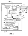
- FIGs. 2A-2B illustrate a analyte testing system 200 including an analyte testing meter 202 and an analyte sensor 100 of the type described in FIGs. 1A-1B electrically coupled thereto.
- the analyte testing meter 202 includes conventional components such as processor 205, memory 210, display 215 (e.g., a liquid-crystal display or the like), user interface 220 (e.g., push buttons, keys, a scroll wheel or ball, touch screens, or any combination thereof), power source 222 (e.g., a 3.0 V power source), power management 223, device interface 224, and electrical contacts 206A, 206B.
- processor 205 e.g., memory 210
- display 215 e.g., a liquid-crystal display or the like
- user interface 220 e.g., push buttons, keys, a scroll wheel or ball, touch screens, or any combination thereof
- power source 222 e.g., a 3.
- the processor 205 may be any suitable processor.
- the processor 205 may be any microprocessor device or collection of microprocessor devices that are capable of receiving the signals and executing any number of program routines, and may be a microcontroller, microprocessor, digital signal processor, or the like.
- a suitable processor is a SoC microprocessor (e.g., a Cortex M3 equipped microprocessor) available from ST Microelectronics or Energy Micro.
- Data received and/or processed by the processor 205 may be stored in memory 210, which may store software routines that may be adapted to process raw analyte data and determine analyte measurement values, and carryout a temperature measurement sequence.
- the microprocessor 205 e.g., a System On Chip (SOC)
- SOC System On Chip
- a routine in software then causes a switch 209 to engage the temperature measurement circuit 204 to enable execution of a temperature measurement sequence.
- the switch 209 may be any suitable switch, such as a multiplexor.
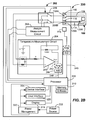
- the temperature measurement circuit 204 functions to record a changing voltage (Vout) that is proportional to a ⁇ T across the analyte sensor 100.
- the changing voltage (Vout) may be caused by a change in the temperature between the cold junction 126A and hot junction 126B of the analyte sensor 100 due to exposure to ambient temperature.
- the switch 209 may be activated by a suitable signal from processor 205 to cause an electrical connection between the temperature measurement circuit 204 and the analyte sensor 100. Once connected, the temperature measurement circuit 204 may execute a temperature sensing routine of the analyte testing sequence.
- a voltage differential may be provided to a differential amplifier 240 and an output may be provided that is proportional to the aforementioned ⁇ T.
- a Vout signal from the amplifier 240 may be amplified, if needed, by optional amplifier 242 and converted by A/D converter 244 to provide a digital output signal in line 246 to the processor 205 that is indicative of a ⁇ T between the cold and hot junctions 126A, 126B of the analyte sensor 100.
- the temperature sensing routine may cause an absolute temperature sensor 225 located in the port of the analyte testing meter 202 and proximate to the cold junction 126B to measure an absolute temperature as another voltage output.
- the absolute temperature digital signal received by the processor 205 in line 245 that is indicative of the temperature at the cold junction 126A and the voltage output digital signal representative of ⁇ T in line 246 may be summed by the temperature sensing routine operating in the processor 205 and may be stored in memory 210.
- the temperature correction constant (C T ) may be obtained either directly or through the use of a look up table or via calculation using a mathematical function.
- This temperature correction constant C T may be used along with a calibration constant C C that is either manually input by the user, read from the packaging (e.g., in the case of multi-sensor packages), or otherwise obtained by interfacing with various electrical contact traces on the analyte sensor 100 (not shown).
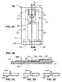
- FIGs. 3A-3B illustrate an example alternative embodiment of an analyte sensor 300 according to another aspect of the invention.
- the structure of the analyte sensor 300 is similar to the aforementioned FIGs. 1A-1B embodiment.
- the analyte sensor 300 includes a first electrode 308 having a contact engagement portion 310 and a sensing portion 312, a second electrode 314 having a contact engagement portion 316 and sensing portion 318, an active region 320 coupled to the electrodes 308, 314 at the sensing portions 312, 318, and a thermocouple portion 326 as above-described.
- the analyte sensor 300 further includes a fuse member 328.
- the fuse member 328 may extend between, and electrically connect, the first electrode 308 and the second electrode 314.
- the fuse member 328 may be at least partially surrounded by a void 331.
- the void 331 may function to allow any gases from the burning of fuse member 328 a place to expand into.
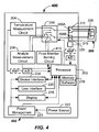
- the fuse member 328 may be formed of any suitable material that may be burnt (e.g., blown) by the application of a predefined voltage and/or current from a fuse member burning circuit 410 in an analyte testing meter 402 as shown in FIGs. 4-5 .
- the fuse member 328 may be manufactured from the same materials as the first conductor 308 (e.g., a gold film).
- the fuse member 328 may be manufactured from any suitable fusing material, and may be a different material than either the first or second electrodes 308, 314.
- the fuse member 328 may include a fuse region of reduced area to control a burn location of the fuse member 328.
- the fuse region of reduced area may be formed by a notch or simply by reducing the thickness or other dimension of the fuse material in the fuse region as compared to other areas of the fuse member 328. Since the fuse member 328 is burned by utilizing the contact engagement portions 310, 316, the fuse member 328 should be configured to exhibit a burn value that is less than a voltage bias that will be applied to the analyte sensor 300, i.e., across the active region 320 during the analyte measurement phase of the analyte testing sequence.
- the burn value (Vb) is defined herein as a value of voltage or current that causes the fuse member 328 to burn fully (fail) thereby eliminating an electrical path across the fuse member 328, i.e., effectively burning (or blowing) the fuse member 328.
- the applied bias voltage across the analyte sensor 300 during an analyte measurement sequence is of the order of about 275 mV to about 625 mV. Therefore, in some embodiments, the burn value (Vb) for the fuse member 328 should be about 250 mV or less. In this way, the fuse member 328 may be included in a way that does not require additional electrical contacts on the analyte sensor 300.
- the fuse member 328 may be sandwiched between the base 302 and the lid 311.
- a sealant 332 may be used to secure the lid 311 to the base 302 should cause the fuse member 328 be sealed relative to the cavity 322.
- the lid 311 may be compressed and thermally formed through application of heat and pressure to seal the lid 311 to the base 304 and seal around the void 331 and fuse member 328.
- the fuse member 328 may be burnt/blown so that the analyte sensor 300 includes an easy mechanism to determine whether the analyte sensor 300 has been previously used.
- functionality within a fuse member burning circuit 410 may burn the fuse member 328 as part of the testing sequence for each analyte sensor 300.
- functionality within the temperature measurement circuit 204 or analyte measurement circuit 208 may carry out the burning of the fuse member 328.
- functionality within the temperature measurement circuit 204, analyte measurement circuit 208, or fuse member burning circuit 410 as shown in FIGs. 4-5 may, before carrying out an analyte testing sequence, first carry out a check for a presence of a burnt fuse member 328. If detected, the functionality may reject the analyte sensor 300, issue a warning, or otherwise disallow any further testing on the analyte sensor 300. Detection of a burnt fuse member 328 may usually be indicative that the analyte sensor 300 may have been previously used.
- the fuse region of reduced area of the fuse member 328 should be made to be relatively very small.
- the cross-sectional area may be about 1.0 x 10 -5 cm 2 or less if a gold material is used to manufacture the fuse member 328.
- the cross-sectional area may be about 3.7 x 10 -5 cm 2 or less.
- the thickness should be less than about 15 ⁇ m.
- the precise dimensions of the fuse member 328 may be controlled by producing the fuse region to an oversized dimension in a first step, and then laser ablating some of the material away via the application of a suitable laser (e.g., an excimer, YAG, or CO 2 laser).
- a suitable laser e.g., an excimer, YAG, or CO 2 laser.
- the dimensions of the fuse regions 328A, 328B, 328C of the fuse member 328 may be precisely formed and controlled, wherein the dotted lines represent the location of the oversized fuse region and the solid lines are the resultant configuration after the laser ablation has taken place.
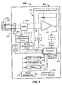
- the fuse member burning circuit 410 of the analyte testing meter 402 will be described in detail.
- the fuse member 328 of the analyte sensor 300 will be burned after the temperature measurements are obtained by the temperature measurement circuit 204 and sensor 225 and before the analyte measurement on the analyte sensor 300 is obtained by analyte measurement circuit 208.
- a signal to the switch 209 from the processor 205 connects the fuse member burning circuit 410 to the analyte sensor 300.
- a signal in line 412 then ramps up the voltage (V DAC ) to the amplifier 414 to an appropriate level where the fuse member 326 is burned thereby creating an electrical open across the fuse member 328.
- This voltage is designed to be less than the voltage bias applied across the analyte sensor 300 during the next analyte measurement step of the sequence carried out by the analyte measurement circuit 208.
- the applied voltage bias will be about 300 mV during the analyte measurement phase of the sequence. Therefore, the voltage for the burn of fuse member 328 should be less than that; preferably less than about 250 mV, for example. Other lower voltages may be used, depending upon the burn value of the fuse member 328.
- Vout may be monitored to determine the occurrence of the burn of the fuse member 328.
- a slope checking algorithm may be used to test Vout for variations in slope of the Vout signal that are above a threshold value. Such slope excursions are indicative of fuse burning.
- the switch 209 is again activated and the analyte measurement is undertaken by analyte measurement circuit 208.
- the previously obtained temperature compensation constant (C T ) is used to adjust the raw measured analyte value (RMAV) to compensate for temperature at or near the location of the reagent on the analyte sensor 300.
- FIG. 6 illustrates a variant of the embodiment of FIG. 3A-3B wherein the fuse member 628 of the analyte sensor 600 is provided as a carbon-based trace extending between the electrodes 608 and 614. All other features are the same as in the FIG. 3A-3B embodiment. In this way, the dimensions and the burn value of the fuse member 628 may be carefully controlled by ink-jet printing of the carbon-based trace by application of a suitable fusible carbon-based ink.
- the first electrode 608 and contact engagement portions 610, 616 may be manufactured from a second material, e.g., a noble metal thin film.
- the thin film may be a gold or platinum film, for example having a thickness of about 100 nm or less. All other features are the same as in the FIG. 3A-3B embodiment.
- the analyte sensor 600 may be readily prepared through the use of a deposition process to deposit the noble metal portions of the first electrode 608, sensing portion 618, and the contact engagement portions 610, 616 followed by providing the carbon-based trace forming the thermocouple portion 626 and the fuse member 628 by an ink-jet process. Additionally, the burn value (Vb) of the fuse member 628 may be carefully controlled via the ink jet deposition process.
- FIG. 7 illustrates yet another variant of the embodiment of an analyte sensor 700 wherein the sensing portion 718 and the thermocouple portion 726 are each formed of a trace of carbon-based material.
- a fuse member 828 may be provided as a carbon-based trace extending between the electrodes 808 and 814 of the analyte sensor 800.
- the first electrode 708 and contact engagement portions 710, 716 may be manufactured from a first material, e.g., a noble metal thin film.
- the thin film may be a gold or platinum film, having a thickness of about 100 nm or less, for example. All other features are the same as in the FIG. 1A-1B embodiment.
- the sensor 700 may be readily prepared through the use of a first deposition process to deposit the noble metal portions of the first electrode 708 and the contact engagement portions 710, 716 followed by providing the carbon-based trace forming the thermocouple portion 726 and the sensing portion 718 of the second electrode 714.
- the second electrode 714 and thermocouple portion may be formed via a suitable deposition process, such as by an ink-jet process depositing carbon-based ink.
- Active region 720 may be deposited thereafter.
- FIG. 8 illustrates another embodiment of the analyte sensor 800.
- the sensor 800 includes a fuse member 828, thermocouple portion 826, and sensing portion 818, all being integrally formed from a carbon-based material.
- the sensor 800 may be readily prepared through the use of a first deposition process to deposit the noble metal portions of the first electrode 808 and the contact engagement portions 810, 816 followed by providing the carbon-based trace forming the thermocouple portion 826 and the sensing portion 818 of the second electrode 814.
- the second electrode 814 and thermocouple portion 826 may be integrally formed via a suitable deposition process, such as by an ink-jet process depositing carbon-based ink. Active region 820 may be deposited thereafter.
- thermocouple portion 326, 626, 826 and a fuse member 328, 628, 828 will now be described with reference to FIG. 9 .
- the method 900 includes the steps of providing an analyte sensor in 902, and coupling the analyte sensor to an analyte testing meter in 904 (e.g., via insertion in the meter 402 such that the contact engagement portions (e.g., 310, 316) of the analyte sensor (e.g., 300) make electrical contact with electrical contacts (e.g., 206A, 206B) in the analyte test meter (e.g., 402).
- Ambient temperature is measured by the use of a temperature sensor 225 (e.g., a thermister) positioned at a location in analyte testing meter 202 adjacent to the electrical contacts 206A, 206B.
- the temperature sensor 225 is used to measure the temperature at a point inside of the analyte testing meter 202 adjacent to the hot junction 126A.
- the actual temperature is the temperature as measured at the temperature sensor 225 plus (or minus) the temperature measured on the body of the analyte sensor 300 in 908 via the temperature measurement circuit 204.
- a ⁇ T is measured between the cold junction 326A and the hot junction 326B of the thermocouple portion 326.
- the difference between the cold and hot junction is added (or subtracted as the case may be) from the absolute temperature measurement obtained by the sensor 225 at or adjacent to the electrical contacts 206A, 206B. Accordingly, the actual temperature of the analyte sensor 300 at the cold junction 326B may be determined.
- This temperature because it is very close to the active region 320, may be used to provide a suitable temperature compensation constant (C T ) for the analyte sensor 300.
- Circuit resistors and capacitors of the temperature measurement circuit are chosen to provide an appropriate temperature compensation constant C T based upon experimental testing.
- a burning the fuse member 328 on the analyte sensor 300 may be accomplished in 910.
- the fuse member burning may be by the operation of a fuse member burning circuit (e.g., fuse member burning circuit 410 shown in FIGs. 4 and 5 ), for example.
- a measured analyte value is measured on the analyte testing meter in 914 via a conventional analyte measurement circuit 208. The calculation of the measured analyte value is achieved by entirely conventional calculation method and shall not be described further herein.
- Measured Analyte Value RMAV ⁇ C c ⁇ C T
- the temperature compensation constant C T may be a linear factor, non-linear factor, or extracted from a lookup table based upon the output of the temperature measurement circuit 204, for example.
- the method 900 may optionally include a step of checking to see if the fuse member (e.g., fuse member 328) of the analyte sensor (e.g., analyte sensor 300) is initially burned in 906 by testing, for example, a resistance across contact engagement portions 310, 316 of the analyte sensor 300 directly after coupling the analyte sensor 300 to an analyte testing meter 402 in 904.
- the method 900 may optionally include a step of checking the fuse member burn in 912 wherein it is checked to see if the fuse member 328 of the analyte sensor 300 was properly burned.
- the test for burn may be by testing a resistance across contact engagement portions 310, 316 of the analyte sensor 300. If resistance is not present, then it is determined that the fuse member 328 may be defective or a counterfeit, etc. and the analyte sensor 300 is determined to be not useable. In this condition, an error message may be provided to the user. Of course, if the fuse member 328 does not burn, then the analyte measurement in 1014 cannot be undertaken.
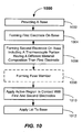
- the method 1000 includes the steps of providing a base (e.g., a base of insulating material) in 1002, and forming a first electrode on a surface of the base in 1004.
- the method 1000 also includes forming a second electrode on the base in 1006.
- the second electrode includes a thermocouple portion having a different material composition as compared to the material composition of the first electrode.
- the thermocouple portion may constitute only a portion of the second electrode.
- a first portion of the second electrode may include a sensing portion and a contact engagement portion, and the thermocouple portion may extend there between.
- the thermocouple portion may be deposited as a carbon-containing trace.
- An active region 120 may be applied to be in contact with at least a portion of the first electrode and at least a portion of the second electrode in 1010. In some embodiments, the active region 120 is provided in contact with only a small portion of the first and second electrodes.
- the electrodes may be formed to include a contact engagement portions adapted to be in electrical contact with first and second electrical contacts of an analyte testing meter (see FIGs. 2A-2B and FIGs. 4-5 ). According to the method 1000, a lid is applied overtop of the base in 1012 to form a cavity in the vicinity of the active region.
- the first electrode and the thermocouple portion must be manufactured from different materials.
- the electrodes may be made of any suitable electrically-conductive material, and may be formed by any suitable method.
- one of the electrodes may be formed with a conductive ink (e.g., a carbon-based ink) using a screen printing, laser printing, or inkjet printing process, for example. Portions of the electrodes may be integrally formed, or formed as two separate components.
- one electrode may be a metal material such as a noble metal (e.g., a gold film). The noble metal may be provided on the base by a sputtering deposition process.
- the electrodes may be formed by adhering or forming a thin conductive film on the base.
- the analyte sensors described herein may further include some form of underfill detection to determine whether a sufficient amount of the biological fluid sample is present in the cavity of the analyte sensor in order to carry out an acceptable analyte concentration measurement.
- underfill detection may be provided by a method described in United States Application Publication 2009/0095071 to Wu et al. entitled "Underfill Detection System for a Biosensor.” Described is a purely electrical solution wherein the method does not require the use of an additional electrode.
Description
- The present invention relates to analyte sensors that may be used to detect an analyte concentration level in a bio-fluid sample, systems including the analyte sensors, and methods of using and manufacturing the analyte sensors.
- The monitoring of analyte concentration levels in a bio-fluid may be an important part of health diagnostics. For example, an electrochemical analyte sensor may be employed for monitoring of a patient's blood glucose level as part of diabetes treatment and care. An electrochemical analyte sensor may be employed, for instance, for detecting an analyte concentration level in a bio-fluid sample such as from a single sample of blood or other interstitial fluid. For example, the bio-fluid may be obtained from the patient using a lancet (e.g., by a pinprick or needle). Typically, after a bio-fluid sample has been obtained, the sample may then be transferred to a medium (e.g., to an analyte sensor) for measurement of the bio-fluid sample's analyte concentration level (e.g., a glucose analyte level).
- It is established that such measurements may be somewhat affected by temperature, as the reagent and the electrochemical reaction may be temperature sensitive. Prior systems have included temperature sensing inside of an analyte testing meter (e.g., a temperature sensor inside of a blood glucose meter (BGM)). However, for various reasons, sensing of temperature inside of the meter, albeit achieving enhanced accuracy as compared to non-temperature compensated analyte meter systems, may induce some error when actual temperature on the sensor (at or near the reagent) is not properly compensated for. Accordingly, it may be beneficial to provide an analyte sensor adapted for bio-fluid analyte testing that may more closely or more elegantly account for temperature changes due to the actual temperature on the analyte sensor. Document
US 2009/0325205 A1 relates to an analyzer for measuring a highly contaminating infectious analysis object, and more particularly relates to an analyzer with a disposable sensor, and to a constitution and measurement method for providing high assay accuracy. - In a first aspect, the present invention provides an analyte sensor according to claim 1. The analyte sensor includes a first electrode having a contact engagement portion and a sensing portion; a second electrode having a contact engagement portion and a sensing portion; an active region provided in contact with, and extending between, the sensing portions of the first electrode and the second electrode; and a thermocouple portion comprising at least part of a conducting path from the Active region to the contact engagement portion of the second electrode.
- Further, an analyte sensor is provided. The analyte includes a base; a first conductor made of a first conductive material extending along the base, the first conductor having a first contact engagement portion and a first sensing portion; a second conductor extending along the base having a second contact engagement portion and a second sensing portion; an active region provided in contact with and extending between the first sensing portion and the second sensing portion; and a thermocouple portion connected between the second contact engagement portion and a second sensing portion of the second electrode, wherein the first contact engagement portion and second contact engagement are the only two contact engagement portions of the analyte sensor.
- In another aspect, the present invention provides an analyte testing system according to claim 11. The analyte testing system includes an analyte sensor including a working electrode having a contact engagement portion and a sensing portion, a counter or reference electrode having a contact engagement portion and a sensing portion, an active region provided in contact with and extending between the sensing portions of working electrode and the counter or reference electrode, and a thermocouple portion connected between the contact engagement portion and a sensing portion of the counter or reference electrode and comprising at least part of a conducting path of the counter or reference electrode; and a temperature measurement circuit provided in electrical contact with the contact engagement portions.
- In a method aspect, the present invention provides a method of testing an analyte sensor according to claim 14. The method includes providing an analyte sensor; coupling the analyte sensor to an analyte testing meter; measuring a temperature on the analyte sensor; burning a fuse member on the analyte sensor; and measuring an analyte value on the analyte testing meter.
- In another method aspect, the present invention provides a method of manufacturing an analyte sensor according to claim 15. The method includes the steps of providing a base; forming a first electrode including a first material on the base; forming a second electrode on the base, the second electrode including a thermocouple portion of a second material different than the first material; applying an active region in contact with the first electrode and the second electrode, wherein the thermocouple portion is at least part of a conducting path from the active region.
- Other features and aspects of the present invention will become more fully apparent from the following detailed description, the appended claims, and the accompanying drawings.
-
-
FIG. 1A is a top plan view of an example embodiment of analyte sensor including a temperature sensing element provided according to a first aspect of the present invention. -
FIG. 1B is a cross-sectioned side view of the example embodiment of analyte sensor ofFIG. 1A taken along section line "1B-1B." -
FIG. 2A is an example embodiment of an analyte testing system including on-body temperature measurement provided according to another aspect of the present invention. -
FIG. 2B is an example embodiment of an analyte testing system including a detailed view of the temperature measurement circuit provided according to another aspect of the present invention. -
FIG. 3A is a top plan view of another example embodiment of an analyte sensor including a fuse member and on-body temperature sensor according to another aspect of the present invention. -
FIG. 3B is a cross-sectioned side view of the example embodiment of analyte sensor ofFIG. 3A taken along section line "3B-3B." -
FIGs. 3C-3E are example embodiments of fuse members including reduced area fuse regions according to aspects of the present invention. -
FIG. 4 is an example embodiment of an analyte testing system including on-body temperature sensing and fuse burning capability according to another aspect of the present invention. -
FIG. 5 is a detailed circuit diagram of an electrical circuit including a fuse member burning circuit adapted to burn a fuse member of an embodiment of analyte sensor according to another aspect of the present invention. -
FIG. 6 is a top plan view of another example embodiment of an analyte sensor including an on-body temperature sensor and fuse member according to an aspect of the present invention. -
FIG. 7 is a top plan view another example embodiment of an analyte sensor including on-body temperature sensor according to an aspect of the present invention. -
FIG. 8 is yet another example embodiment of an analyte sensor including an on-body temperature sensor and fuse member according to an aspect of the present invention. -
FIG. 9 is a flowchart illustrating methods of using the analyte sensor according to embodiments of the present invention. -
FIG. 10 is a flowchart illustrating methods of manufacturing the analyte sensor according to embodiments of the present invention. - According to some aspects of the present invention, an improved temperature-sensing analyte sensor is provided. As discussed above, although monitoring temperature inside the BGM may offer enhanced accuracy, it is desirable to sense the temperature at a location that is relatively closer to the actual site of the reaction, i.e., on the body of the analyte sensor (e.g., on the test strip). Including a temperature sensor on the body of the analyte sensor is referred to herein as having an "on-body temperature sensor."
- For example, in analyte testing systems that are adapted to receive an analyte sensor in a port of an analyte testing meter, the part of the analyte sensor that actually contains the reagent may be located at a position outside of the physical confines of the analyte testing meter, and, therefore, may be exposed directly to the ambient environment. Because the thermal mass of the analyte sensor is substantially lower than of the analyte testing meter, the analyte sensor is prone to rapid changes in temperature and may equilibrate with ambient temperature very quickly. However, because the thermal mass of the analyte testing meter is relatively higher than the analyte sensor, the meter may more slowly equilibrate with ambient temperature. Accordingly, the temperature of the actual site where the reaction is taking place may be somewhat different than the temperature inside of the analyte testing meter. The present invention accounts for this difference.
- In the way of a real-world example, a user may take the analyte testing meter (e.g., BGM) out of their pocket, and then may insert an analyte sensor into a port of the meter. The actual site where the reagent is located on the analyte sensor may be exposed to relatively cold weather (e.g., 30 degrees F or less) and because of its relatively low thermal mass may quickly equilibrate so as to be at or very near to the ambient temperature whereas the temperature inside of the analyte testing meter may be relatively warmer.
- In view of this concern, the present invention provides an analyte sensor having an on-body temperature sensor (e.g., that is resident on the body of the analyte sensor) such that the actual temperature of the reagent may be approximately accounted for. The analyte sensor may include first and second electrodes each having a contact engagement portion and a sensing portion, an active region provided in contact with, and extending between, the sensing portions of the first electrode and second electrode, and a thermocouple portion connected between the contact engagement portion and a sensing portion of the second electrode. The thermocouple portion may comprise at least a part of a conducting path from the active region to the contact engagement portion of the second electrode.
- More simply, a thermocouple is embodied by the first and second electrodes thereby forming an on-body sensor. Accordingly, in some embodiments, the analyte sensor may include two, and only two, electrical contacts thereby significantly simplifying the act of making of an electrical connection with the analyte testing meter. The analyte sensor of the present invention may be used to measure any number of analytes, such as glucose, fructose, lactate, keytone, microalbumin, bilirubin, total cholesterol, uric acid, lipids, triglyceride, high density lipoprotein (HDL), low density lipoprotein (LDL), hemoglobin A1c etc. The analytes may be detected in, for example, whole blood, blood serum, blood plasma, interstitial fluid, urine, etc. Other types of analytes may be measured provided a suitable reagent exists.
- In other embodiments, an analyte testing system is provided. The analyte testing system includes an analyte sensor including a working electrode having a contact engagement portion and a sensing portion, a counter (or reference) electrode having a contact engagement portion and a sensing portion, an active region provided in contact with and extending between the sensing portions of working electrode and the counter (or reference) electrode, and a thermocouple portion connected between the contact engagement portion and a sensing portion of the counter (or' reference) electrode and comprising at least a part of a conducting path of the counter electrode, and a temperature measurement circuit provided in electrical contact with the contact engagement portions (that may number two, and only two).
- These and other embodiments of analyte sensors, analyte testing systems and apparatus including the analyte sensors, and methods of using and manufacturing the analyte sensor are described below with reference to
FIGs. 1A-10 . -
FIGs. 1A-1B illustrate a top and a cross-sectioned side view, respectively, of a first example embodiment of ananalyte sensor 100 provided according to a first aspect of the present invention. Theanalyte sensor 100 may include a sensor body including a base 102 preferably formed of an insulating material. The base 102 may have afirst end 104 and asecond end 106 opposite thefirst end 104 and spaced therefrom, and may be relatively planar in shape. The base 102 may be any suitable shape, such a rectangular, or other polygonal shapes. Other shapes may be used. The base 102 may be manufactured from of a suitable polymer material, such as a polycarbonate, polyethylene terephthalate (PET), polyethelyle naphthalate (PEN), polyimide, high density polyethylene, or polystyrene material, or combinations, for example. Other materials may be used. The base 102 may be manufactured by being stamped out of a sheet of material, thermally formed, extruded, or molded, for example. - The
analyte sensor 100 includes a first electrode 108 (e.g., a working electrode) that in the depicted embodiment may extend along the base 102 from thefirst end 104 to thesecond end 106. Thefirst electrode 108 includes acontact engagement portion 110 and asensing portion 112. Thecontact engagement portion 110 may be enlarged relative to the extending portion of theelectrode 108, located on thefirst end 104, and adapted to be contacted by an electrical contact of an analyte testing meter. Asensing portion 112 may be located on thesecond end 106. - Likewise, a second electrode 114 (e.g., a reference or counter electrode) may extend along the base 102 from the
first end 104 to the,second end 106. Thesecond electrode 114 includes acontact engagement portion 116 and asensing portion 118. Thecontact engagement portion 116 may be enlarged relative to an extending portion of the electrode, may be located on thefirst end 104, and may be adapted to be contacted by an electrical contact of an analyte testing meter. Thecontact engagement portions sensing portion 112, thesensing portion 118 may be located on thesecond end 106. Thesensing portion 118 may be positioned opposite of thesensing portion 112. - An
active region 120, that may be located at on thesecond end 106, is provided in engaging contact with the first andsecond electrodes active region 120 extends between the opposed sensingportions active region 120 may be an electrochemically-active region including one or more catalytic agents or reagents adapted to react with a biological fluid that is provided in contact with theactive region 120 during analyte measurement. - The
first electrode 108 may be positioned partially underneath of theactive region 120 such that there is an electrical coupling with thefirst electrode 108. The firstcontact engagement portion 110 is adapted to be in electrical contact with a first electrical contact of an analyte testing meter 202 (SeeFIGs. 2A-2B ). Thefirst electrode 108 andsecond electrodes 114 may be made from any suitable electrically-conductive material. Suitable conductive materials include carbon, graphite, noble metals such as gold, palladium, or platinum, silver, combinations of the aforementioned, or the like. In some embodiments, the electrodes may be made from a carbon/graphite PTF, silver/silver chloride, or an electrically-conductive ink such as a carbon- and silver-containing ink. As will be described more thoroughly below, theelectrodes - Sensing
portions electrodes base 102 and may include any suitable construction. For example, a single gap may be provided, or interleaved electrode fingers may form multiple gaps. Theactive region 120, as before described, may be applied over the sensingportions active region 120. - The
active region 120 may be adapted to promote an electrochemical reaction between an analyte in the biological fluid sample and the catalytic agents or reagents included in theactive region 120, or otherwise generate a detectible electrical current upon being exposed to the biological fluid sample. The mobile electrons produced may be conducted to an analyte testing meter 202 (FIGs. 2A-2B ), for example. A voltage bias is generally applied to theelectrodes analyte sensor 100 during the analyte measurement step of the testing sequence, i.e. when actually taking/recording a raw analyte concentration measurement. - One group of catalytic agents useful for providing the
active region 120 may be the class of oxidase enzymes which includes, for example, glucose oxidase (which converts glucose), lactate oxidase (which converts lactate), and D-aspartate oxidase (which converts D-aspartate and D-glutamate). In embodiments in which glucose is the analyte of interest, glucose dehydrogenase (GDH) may optionally be used. Pyrolloquinoline quinine (PQQ) or flavin adenine dinucleotide (FAD) dependent may also be used. A more detailed list of oxidase enzymes that may be employed in the present invention is provided inU.S. Patent No. 4,721,677 , entitled "Implantable Gas-containing Biosensor and Method for Measuring an Analyte such as Glucose" to Clark Jr. Catalytic enzymes other than oxidase enzymes may also be used. - The
active region 120 may include one or more layers (not explicitly shown) in which the catalytic agents (e.g., enzymes) and/or other reagents may be immobilized or deposited. The one or more layers may comprise various polymers, for example, including silicone-based or organic polymers such as polyvinylpyrrolidone, polyvinylalcohol, polyethylene oxide, cellulosic polymers such as hydroxyethylcellulose or carboxymethyl cellulose, polyethylenes, polyurethanes, polypropylenes, polyterafluoroethylenes, block co-polymers, sol-gels, etc. A number of different techniques may be used to immobilize the enzymes in the one or more layers in theactive region 120 including, but not limited to, coupling the enzymes to the lattice of a polymer matrix such as a sol gel, cross-linking the agents to a suitable matrix such as glutaraldehyde, electropolymerization, and formation of an array between the enzymes via covalent binding, or the like. - In some embodiments, a mediator may be included within the
active region 120 to promote the conversion of the analyte to detectable reaction products. Mediators comprise substances that act as intermediaries between the catalytic agent and the electrode. For example, a mediator may promote electron transfer between the reaction center where catalytic breakdown of an analyte takes place and the electrode. Suitable mediators may include one or more of the following: metal complexes including ferrocene and its derivatives, ferrocyanide, phenothiazine derivatives, osmium complexes, quinines, phthalocyanines, organic dyes as well as other substances. In some embodiments, the mediators may be cross-linked along with catalytic agents directly to the first andsecond electrodes - In some embodiments, a
lid 111 may be provided overtop of thebase 102. Thelid 111 may be fused or otherwise adhered to thebase 102 by application of heat and pressure, for example. Other means of fastening thelid 111 may be employed, such as by the use of an adhesive or a sealant. Thelid 111 may be formed, such as by stamping, cold forming, or heat forming. Thelid 111 andbase 102 when fastened together cooperate to form acavity 122 that may extend from thesecond end 106 towards the location of theactive region 120. Thecavity 122 may provide a capillary channel into which a biological fluid sample applied at the end of thecavity 122 by a user may pass. Thelid 111 may be manufactured from a deformable polymer material, such as polycarbonate, an embossable grade of polyethylenetherephthalate, or a glycol modified polyethylenetherephthalate, for example. Other types of materials may be used. A polyurethane dielectric material may be applied over an area encompassed by thelid 111 and may aid in sealing thelid 111 to thebase 102. Further details of the structure of thelid 111 andbase 102, as well as attachment details may be found inU.S. Pat. No. 5,759,364 . - A
vent 124 in the form of a hole or perforation may be provided at an end of thecavity 122 to improve capillary action and flow of the biological fluid sample into thecavity 122 from thesecond end 106 when applied thereat by the user. Thecavity 122 may be at least partially formed and defined, for example, by the inner surfaces of thelid 111,base 102, and the upper surface of theactive region 120. Thecavity 122 may have any shape, but preferably a shape that promotes capillary action to cause a droplet of biological fluid to be drawn into thecavity 122 when applied to the entrance of thecavity 122 by the user. The bio-fluid sample may be drawn into thecavity 122 and come into intimate contact with theactive region 120. Thecavity 122 may have a length of about 2 mm to 5 mm, a width of about 0.5 mm to 1.5 mm, and a height of about 0.05 mm to 0.25 mm, for example. Other dimensions may be used. - In the depicted embodiment, the
sensing portion 118 of thesecond electrode 114 includes a configuration making electrical contact with theactive region 120. For example, theactive region 120 may be provided/applied overtop of an end portion of thesensing portion 118 located opposite thesensing portion 112. Thesecond electrode 114 may include acontact engaging portion 116 on thefirst end 104 that is adapted to make electrical contact with an electrical contact of an analyte testing meter (e.g.analyte testing meter 202 shown inFIGs. 2A-2B ). In between thefirst end 104 and thesecond end 106 and extending between the sensingend 118 and thecontact engaging portion 116 of thesecond electrode 114 is athermocouple portion 126. In the depicted embodiment, thethermocouple portion 126 is connected between acold sensing junction 126A on thesensing portion 118 and ahot sensing junction 126B on thecontact engagement portion 116. The other portion of the thermocouple comprises a portion of thefirst electrode 108. - To establish a thermocouple, the
thermocouple portion 126 may be manufactured from a material that is different than (dissimilar) to the material used to manufacture thefirst electrode 108. In the depicted embodiment, thethermocouple portion 126 comprises a part of the conducting path 128 (shown in phantom lines). The conductingpath 128 during administration of a temperature test is the same as for an analyte measurement test. A voltage bias is applied across thecontact engagement portions first electrode 108,active region 120, andsecond electrode 114. In particular, thethermocouple portion 126 is part of the conducting path between theactive region 120 and thecontact engagement portion 116 of thesecond electrode 114. In other words, during the testing/measurement step of the testing sequence wherein a voltage bias is applied across thecontact engagement portions thermocouple portion 126. Thus, it should be recognized that thethermocouple portion 126 lies in a directcurrent conducting path 128 during both the temperature measurement phase and the analyte measurement phase of the testing sequence. Generally, the temperature measurement phase takes place first, followed by the analyte measurement phase. - In the illustrated embodiment of
FIGs. 1A-1B , thethermocouple portion 126 is a trace of a carbon-based material, such as a carbon-containing ink. In particular, in the depicted embodiment, thecontact engagement portion 116 and thesensing portion 118 may be manufactured from the same material as the first electrode 108 (e.g., a gold film). Thethermocouple portion 126 may then be applied overtop of thecontact engagement portion 116 and thesensing portion 114 at thejunctions - In particular, the
thermocouple portion 126 must comprise a different conductive material than a portion of thefirst electrode 108. In the depicted embodiment, thefirst electrode 108 may be a noble metal (e.g., a gold, platinum, or palladium film) and thethermocouple portion 126 may be a trace of a carbon-based material. However, any two sufficiently dissimilar materials may be used that provided a sufficient thermocouple effect. - By forming a thermocouple including the
first electrode 108 and thethermocouple portion 126, a representative temperature measurement may be obtained by a temperature measurement circuit 204 (FIGs. 2A-2B ) of theanalyte testing meter 202 being electrically coupled thereto. The temperature measurement may be based upon thermoelectric principles (e.g., the Peltier-Seebeck effect). Once a temperature value has been obtained in the temperature measurement phase, that temperature value may be used to provide a temperature correction constant (CT) to appropriately adjust the analyte measurement taken on theanalyte sensor 100 for temperature on theanalyte sensor 100 at or near the location of theactive region 120. Accordingly, the actual ambient temperature on theanalyte sensor 100 at a location near the site of theactive region 120 may be approximately accounted for. This temperature correction may be in addition to a calculation adjustment that is made to accommodate for lot-to-lot or batch-to-batch variations wherein a calibration constant (CC) is determined and used in the calculation of the analyte concentration. - In the depicted embodiment, the
analyte sensor 100 may include two, and only two,contact engagement portions contact engagement portions analyte sensor 100. As mentioned above, this dramatically simplifies the making of an electrical contact with theanalyte sensor 100, by requiring only twoelectrical contacts analyte testing meter 202 that are adapted to engage thecontact engagement portions - In some embodiments, the
thermocouple portion 126 may be printed onto thebase 102 and overtop of parts of thecontact engagement portion 116 and thesensing portion 118 with a conductive ink by a screen printing process, ink jet process, or other deposition process, for example. Thethermocouple portion 126 may have a width (Wt) of about 0.5 mm to about 1.5 mm, a length (Lt) of about 5 mm to about 25 mm, and a thickness of about 0.01 mm to about 0.1 mm, for example. Other sizes may be used. In a preferred embodiment, a conductive ink may be used, such as a carbon-based ink. However, any suitable conductive electrode ink may be used. - As shown in
FIG. 1A , theanalyte sensor 100 may include a length (L) of between about 15 mm and 35 mm, for example. Theanalyte sensor 100 may include a maximum width (W) of between about 3 mm and 10 mm, for example. Other length (L) and width (W) dimensions may be used. - In operation, upon insertion of a droplet of biological fluid sample into the
cavity 122 such that the fluid comes into contact with theactive region 120, and upon application of a suitable voltage bias across theelectrodes 108, 114 (e.g., about 300 mV), an electrical current may be generated that may be proportional to a concentration of the analyte present in the biological fluid sample. This sensed electrical current may then be conducted by the electrical circuit including the first andsecond electrodes thermocouple portion 126, the electrical contacts 206a, 206b, and an analyte measurement circuit 208 (SeeFIG. 2 ). The calculation of the analyte measurement may be by any currently known method. As discussed above, reagent variations are generally accounted for by using a calibration constant (CC). However, either the calibration constant (CC) or the analyte concentration calculation, according to an aspect of the invention, may be adjusted with a temperature compensation constant (CT) that is obtained by thetemperature measurement circuit 204 as will be described more fully below. The measured analyte concentration (appropriately compensated for analyte variations and temperature) may then be displayed in any suitable readout form, such as in a digital display of the analyte testing system 200 (e.g., a blood glucose meter) as shown inFIGs. 2A-2B . - In more detail,
FIGs. 2A-2B illustrate aanalyte testing system 200 including ananalyte testing meter 202 and ananalyte sensor 100 of the type described inFIGs. 1A-1B electrically coupled thereto. In accordance with an aspect of the invention, theanalyte testing meter 202 includes conventional components such asprocessor 205,memory 210, display 215 (e.g., a liquid-crystal display or the like), user interface 220 (e.g., push buttons, keys, a scroll wheel or ball, touch screens, or any combination thereof), power source 222 (e.g., a 3.0 V power source),power management 223,device interface 224, andelectrical contacts processor 205 may be any suitable processor. For example, theprocessor 205 may be any microprocessor device or collection of microprocessor devices that are capable of receiving the signals and executing any number of program routines, and may be a microcontroller, microprocessor, digital signal processor, or the like. For example, a suitable processor is a SoC microprocessor (e.g., a Cortex M3 equipped microprocessor) available from ST Microelectronics or Energy Micro. Data received and/or processed by theprocessor 205 may be stored inmemory 210, which may store software routines that may be adapted to process raw analyte data and determine analyte measurement values, and carryout a temperature measurement sequence. - In operation, as an
analyte sensor 100 including an on-board temperature sensor is inserted into a port of theanalyte testing meter 202 and contact is made between theelectrical contacts contact engagement portions 110, 116 (thereby making contact with eachelectrodes 108, 114), the microprocessor 205 (e.g., a System On Chip (SOC)) may be awakened. This may be provided by a conventional resistance measuring circuit in theanalyte measurement circuit 208, or by simply powering up theanalyte testing meter 202, for example. A routine in software then causes aswitch 209 to engage thetemperature measurement circuit 204 to enable execution of a temperature measurement sequence. Theswitch 209 may be any suitable switch, such as a multiplexor. - The
temperature measurement circuit 204, as best shown inFIGs. 2A and2B , functions to record a changing voltage (Vout) that is proportional to a ΔT across theanalyte sensor 100. In particular, the changing voltage (Vout) may be caused by a change in the temperature between thecold junction 126A andhot junction 126B of theanalyte sensor 100 due to exposure to ambient temperature. Theswitch 209 may be activated by a suitable signal fromprocessor 205 to cause an electrical connection between thetemperature measurement circuit 204 and theanalyte sensor 100. Once connected, thetemperature measurement circuit 204 may execute a temperature sensing routine of the analyte testing sequence. Once started, a voltage differential may be provided to adifferential amplifier 240 and an output may be provided that is proportional to the aforementioned ΔT. A Vout signal from theamplifier 240 may be amplified, if needed, byoptional amplifier 242 and converted by A/D converter 244 to provide a digital output signal inline 246 to theprocessor 205 that is indicative of a ΔT between the cold andhot junctions analyte sensor 100. - Likewise, the temperature sensing routine may cause an
absolute temperature sensor 225 located in the port of theanalyte testing meter 202 and proximate to thecold junction 126B to measure an absolute temperature as another voltage output. The absolute temperature digital signal received by theprocessor 205 inline 245 that is indicative of the temperature at thecold junction 126A and the voltage output digital signal representative of ΔT inline 246 may be summed by the temperature sensing routine operating in theprocessor 205 and may be stored inmemory 210. - From these digital output values the temperature correction constant (CT) may be obtained either directly or through the use of a look up table or via calculation using a mathematical function. This temperature correction constant CT may be used along with a calibration constant CC that is either manually input by the user, read from the packaging (e.g., in the case of multi-sensor packages), or otherwise obtained by interfacing with various electrical contact traces on the analyte sensor 100 (not shown).
-
FIGs. 3A-3B illustrate an example alternative embodiment of ananalyte sensor 300 according to another aspect of the invention. The structure of theanalyte sensor 300 is similar to the aforementionedFIGs. 1A-1B embodiment. In particular, theanalyte sensor 300 includes afirst electrode 308 having acontact engagement portion 310 and asensing portion 312, asecond electrode 314 having acontact engagement portion 316 andsensing portion 318, anactive region 320 coupled to theelectrodes sensing portions thermocouple portion 326 as above-described. However, in this embodiment, theanalyte sensor 300 further includes afuse member 328. Thefuse member 328 may extend between, and electrically connect, thefirst electrode 308 and thesecond electrode 314. Thefuse member 328 may be at least partially surrounded by avoid 331. The void 331 may function to allow any gases from the burning of fuse member 328 a place to expand into. - In more detail, the
fuse member 328 may be formed of any suitable material that may be burnt (e.g., blown) by the application of a predefined voltage and/or current from a fusemember burning circuit 410 in ananalyte testing meter 402 as shown inFIGs. 4-5 . In the depicted embodiment, thefuse member 328 may be manufactured from the same materials as the first conductor 308 (e.g., a gold film). However, alternatively, thefuse member 328 may be manufactured from any suitable fusing material, and may be a different material than either the first orsecond electrodes fuse member 328 may include a fuse region of reduced area to control a burn location of thefuse member 328. The fuse region of reduced area may be formed by a notch or simply by reducing the thickness or other dimension of the fuse material in the fuse region as compared to other areas of thefuse member 328. Since thefuse member 328 is burned by utilizing thecontact engagement portions fuse member 328 should be configured to exhibit a burn value that is less than a voltage bias that will be applied to theanalyte sensor 300, i.e., across theactive region 320 during the analyte measurement phase of the analyte testing sequence. The burn value (Vb) is defined herein as a value of voltage or current that causes thefuse member 328 to burn fully (fail) thereby eliminating an electrical path across thefuse member 328, i.e., effectively burning (or blowing) thefuse member 328. Generally, the applied bias voltage across theanalyte sensor 300 during an analyte measurement sequence is of the order of about 275 mV to about 625 mV. Therefore, in some embodiments, the burn value (Vb) for thefuse member 328 should be about 250 mV or less. In this way, thefuse member 328 may be included in a way that does not require additional electrical contacts on theanalyte sensor 300. As shown, thefuse member 328 may be sandwiched between the base 302 and thelid 311. Asealant 332 may be used to secure thelid 311 to the base 302 should cause thefuse member 328 be sealed relative to thecavity 322. Optionally, thelid 311 may be compressed and thermally formed through application of heat and pressure to seal thelid 311 to the base 304 and seal around thevoid 331 andfuse member 328. - In the depicted embodiment, the
fuse member 328 may be burnt/blown so that theanalyte sensor 300 includes an easy mechanism to determine whether theanalyte sensor 300 has been previously used. For example, functionality within a fusemember burning circuit 410 may burn thefuse member 328 as part of the testing sequence for eachanalyte sensor 300. Optionally, functionality within thetemperature measurement circuit 204 oranalyte measurement circuit 208 may carry out the burning of thefuse member 328. - Additionally, as part of the analyte testing sequence, functionality within the
temperature measurement circuit 204,analyte measurement circuit 208, or fusemember burning circuit 410 as shown inFIGs. 4-5 may, before carrying out an analyte testing sequence, first carry out a check for a presence of aburnt fuse member 328. If detected, the functionality may reject theanalyte sensor 300, issue a warning, or otherwise disallow any further testing on theanalyte sensor 300. Detection of aburnt fuse member 328 may usually be indicative that theanalyte sensor 300 may have been previously used. - To achieve a burn value (Vb) for the
fuse member 328 of about 250 mV or less, the fuse region of reduced area of thefuse member 328 should be made to be relatively very small. For example, the cross-sectional area may be about 1.0 x 10⁻⁵ cm2 or less if a gold material is used to manufacture thefuse member 328. For a carbon-based material, the cross-sectional area may be about 3.7 x 10⁻⁵ cm2 or less. Thus, for a 10 mil wide carbon-based burn member, the thickness should be less than about 15 µm. - The precise dimensions of the
fuse member 328 may be controlled by producing the fuse region to an oversized dimension in a first step, and then laser ablating some of the material away via the application of a suitable laser (e.g., an excimer, YAG, or CO2 laser). In this way, as best shown inFIGs. 3C-3E , the dimensions of thefuse regions fuse member 328 may be precisely formed and controlled, wherein the dotted lines represent the location of the oversized fuse region and the solid lines are the resultant configuration after the laser ablation has taken place. - Now referring to the
analyte testing system 400 ofFIGs. 4-5 , the fusemember burning circuit 410 of theanalyte testing meter 402 will be described in detail. Thefuse member 328 of theanalyte sensor 300 will be burned after the temperature measurements are obtained by thetemperature measurement circuit 204 andsensor 225 and before the analyte measurement on theanalyte sensor 300 is obtained byanalyte measurement circuit 208. To undertake the burn sequence, a signal to theswitch 209 from theprocessor 205 connects the fusemember burning circuit 410 to theanalyte sensor 300. A signal inline 412 then ramps up the voltage (VDAC) to theamplifier 414 to an appropriate level where thefuse member 326 is burned thereby creating an electrical open across thefuse member 328. This voltage is designed to be less than the voltage bias applied across theanalyte sensor 300 during the next analyte measurement step of the sequence carried out by theanalyte measurement circuit 208. Typically, the applied voltage bias will be about 300 mV during the analyte measurement phase of the sequence. Therefore, the voltage for the burn offuse member 328 should be less than that; preferably less than about 250 mV, for example. Other lower voltages may be used, depending upon the burn value of thefuse member 328. - Vout may be monitored to determine the occurrence of the burn of the
fuse member 328. For example, a slope checking algorithm may be used to test Vout for variations in slope of the Vout signal that are above a threshold value. Such slope excursions are indicative of fuse burning. - Once the burning of the
fuse member 328 is accomplished, theswitch 209 is again activated and the analyte measurement is undertaken byanalyte measurement circuit 208. As is discussed below, the previously obtained temperature compensation constant (CT) is used to adjust the raw measured analyte value (RMAV) to compensate for temperature at or near the location of the reagent on theanalyte sensor 300. -
FIG. 6 illustrates a variant of the embodiment ofFIG. 3A-3B wherein thefuse member 628 of theanalyte sensor 600 is provided as a carbon-based trace extending between theelectrodes FIG. 3A-3B embodiment. In this way, the dimensions and the burn value of thefuse member 628 may be carefully controlled by ink-jet printing of the carbon-based trace by application of a suitable fusible carbon-based ink. - The
first electrode 608 andcontact engagement portions FIG. 3A-3B embodiment. In this way, theanalyte sensor 600 may be readily prepared through the use of a deposition process to deposit the noble metal portions of thefirst electrode 608, sensingportion 618, and thecontact engagement portions thermocouple portion 626 and thefuse member 628 by an ink-jet process. Additionally, the burn value (Vb) of thefuse member 628 may be carefully controlled via the ink jet deposition process. -
FIG. 7 illustrates yet another variant of the embodiment of ananalyte sensor 700 wherein thesensing portion 718 and thethermocouple portion 726 are each formed of a trace of carbon-based material. Optionally, as shown inFIG. 8 , afuse member 828 may be provided as a carbon-based trace extending between theelectrodes analyte sensor 800. In the depicted embodiment ofFIG. 7 , thefirst electrode 708 andcontact engagement portions 710, 716 may be manufactured from a first material, e.g., a noble metal thin film. The thin film may be a gold or platinum film, having a thickness of about 100 nm or less, for example. All other features are the same as in theFIG. 1A-1B embodiment. In this way, thesensor 700 may be readily prepared through the use of a first deposition process to deposit the noble metal portions of thefirst electrode 708 and thecontact engagement portions 710, 716 followed by providing the carbon-based trace forming thethermocouple portion 726 and thesensing portion 718 of thesecond electrode 714. Thesecond electrode 714 and thermocouple portion may be formed via a suitable deposition process, such as by an ink-jet process depositing carbon-based ink.Active region 720 may be deposited thereafter. - As discussed above,
FIG. 8 illustrates another embodiment of theanalyte sensor 800. Thesensor 800 includes afuse member 828,thermocouple portion 826, andsensing portion 818, all being integrally formed from a carbon-based material. In this way, thesensor 800 may be readily prepared through the use of a first deposition process to deposit the noble metal portions of thefirst electrode 808 and thecontact engagement portions thermocouple portion 826 and thesensing portion 818 of thesecond electrode 814. Thesecond electrode 814 andthermocouple portion 826 may be integrally formed via a suitable deposition process, such as by an ink-jet process depositing carbon-based ink.Active region 820 may be deposited thereafter. - Methods of testing embodiments of the
analyte sensor thermocouple portion fuse member FIG. 9 . In one aspect, themethod 900 includes the steps of providing an analyte sensor in 902, and coupling the analyte sensor to an analyte testing meter in 904 (e.g., via insertion in themeter 402 such that the contact engagement portions (e.g., 310, 316) of the analyte sensor (e.g., 300) make electrical contact with electrical contacts (e.g., 206A, 206B) in the analyte test meter (e.g., 402). Ambient temperature is measured by the use of a temperature sensor 225 (e.g., a thermister) positioned at a location inanalyte testing meter 202 adjacent to theelectrical contacts temperature sensor 225 is used to measure the temperature at a point inside of theanalyte testing meter 202 adjacent to thehot junction 126A. The actual temperature is the temperature as measured at thetemperature sensor 225 plus (or minus) the temperature measured on the body of theanalyte sensor 300 in 908 via thetemperature measurement circuit 204. In particular, a ΔT is measured between the cold junction 326A and the hot junction 326B of thethermocouple portion 326. The difference between the cold and hot junction is added (or subtracted as the case may be) from the absolute temperature measurement obtained by thesensor 225 at or adjacent to theelectrical contacts analyte sensor 300 at the cold junction 326B may be determined. This temperature, because it is very close to theactive region 320, may be used to provide a suitable temperature compensation constant (CT) for theanalyte sensor 300. Circuit resistors and capacitors of the temperature measurement circuit are chosen to provide an appropriate temperature compensation constant CT based upon experimental testing. - Once the temperature of the
analyte sensor 300 has been determined, a burning thefuse member 328 on theanalyte sensor 300 may be accomplished in 910. The fuse member burning may be by the operation of a fuse member burning circuit (e.g., fusemember burning circuit 410 shown inFIGs. 4 and5 ), for example. Finally, a measured analyte value is measured on the analyte testing meter in 914 via a conventionalanalyte measurement circuit 208. The calculation of the measured analyte value is achieved by entirely conventional calculation method and shall not be described further herein. The only variation is that an adjustment is made in the calculation for both temperature at the cold junction (using CT) and for lot-to-lot or batch-to-batch calibration (Using CC) as follows:
- RMAV = Raw Measured Analyte Value,
- CC = Calibration Constant, and
- CT = Temperature compensation Constant.
- The temperature compensation constant CT may be a linear factor, non-linear factor, or extracted from a lookup table based upon the output of the
temperature measurement circuit 204, for example. - The
method 900 may optionally include a step of checking to see if the fuse member (e.g., fuse member 328) of the analyte sensor (e.g., analyte sensor 300) is initially burned in 906 by testing, for example, a resistance acrosscontact engagement portions analyte sensor 300 directly after coupling theanalyte sensor 300 to ananalyte testing meter 402 in 904. Once thefuse member 328 is actually burned in 910, themethod 900 may optionally include a step of checking the fuse member burn in 912 wherein it is checked to see if thefuse member 328 of theanalyte sensor 300 was properly burned. Again, the test for burn may be by testing a resistance acrosscontact engagement portions analyte sensor 300. If resistance is not present, then it is determined that thefuse member 328 may be defective or a counterfeit, etc. and theanalyte sensor 300 is determined to be not useable. In this condition, an error message may be provided to the user. Of course, if thefuse member 328 does not burn, then the analyte measurement in 1014 cannot be undertaken. - Methods for manufacturing embodiments of the
analyte sensors FIG. 10 . Themethod 1000 includes the steps of providing a base (e.g., a base of insulating material) in 1002, and forming a first electrode on a surface of the base in 1004. Themethod 1000 also includes forming a second electrode on the base in 1006. The second electrode includes a thermocouple portion having a different material composition as compared to the material composition of the first electrode. In some embodiments, the thermocouple portion may constitute only a portion of the second electrode. For example, a first portion of the second electrode may include a sensing portion and a contact engagement portion, and the thermocouple portion may extend there between. The thermocouple portion may be deposited as a carbon-containing trace. Anactive region 120 may be applied to be in contact with at least a portion of the first electrode and at least a portion of the second electrode in 1010. In some embodiments, theactive region 120 is provided in contact with only a small portion of the first and second electrodes. The electrodes may be formed to include a contact engagement portions adapted to be in electrical contact with first and second electrical contacts of an analyte testing meter (seeFIGs. 2A-2B andFIGs. 4-5 ). According to themethod 1000, a lid is applied overtop of the base in 1012 to form a cavity in the vicinity of the active region. As discussed above, in order to form a thermocouple, the first electrode and the thermocouple portion must be manufactured from different materials. - As discussed above, the electrodes may be made of any suitable electrically-conductive material, and may be formed by any suitable method. For example, one of the electrodes may be formed with a conductive ink (e.g., a carbon-based ink) using a screen printing, laser printing, or inkjet printing process, for example. Portions of the electrodes may be integrally formed, or formed as two separate components. In some embodiments, one electrode may be a metal material such as a noble metal (e.g., a gold film). The noble metal may be provided on the base by a sputtering deposition process. Optionally, the electrodes may be formed by adhering or forming a thin conductive film on the base.
- The analyte sensors described herein may further include some form of underfill detection to determine whether a sufficient amount of the biological fluid sample is present in the cavity of the analyte sensor in order to carry out an acceptable analyte concentration measurement. For example, underfill detection may be provided by a method described in United States Application Publication
2009/0095071 to Wu et al. entitled "Underfill Detection System for a Biosensor." Described is a purely electrical solution wherein the method does not require the use of an additional electrode. - The foregoing description discloses only example embodiments of analyte sensors, systems and apparatus including the such analytes sensors, and methods of manufacturing and using the analyte sensors of the invention. Modifications of the above-disclosed analyte sensors, systems and apparatus incorporating them, and methods for manufacturing and using them, which fall within the scope of the invention, will be readily apparent to those of ordinary skill in the art.
- Accordingly, while the present invention has been disclosed in connection with example embodiments thereof, it should be understood that other embodiments may fall within the scope of the following claims.
Claims (15)
- An analyte sensor (100), comprising:a first electrode (108) having a contact engagement portion (110) and a sensing portion (112);a second electrode (114) having a contact engagement(116) portion and a sensing portion (118);an active region (120) provided in contact with, and extending between, the sensing portions (12, 118) of the first electrode (108) and the second electrode (114);characterized in
a thermocouple portion (126) comprising at least part of a conducting path from the active region (120) to the contact engagement portion (116) of the second electrode (114). - The analyte sensor (100)of claim 1, wherein the first electrode (108) comprises a working electrode, and the second electrode (114) comprises a counter or reference electrode.
- The analyte sensor (100) of claim 1, wherein the contact engagement portions (110, 116) are the only two contact engagement portions of the analyte sensor (100).
- The analyte sensor (100) of claim 1, comprising a base (102), the first electrode (108) and the second electrode (114) extending along the base (102),
wherein preferably the first electrode (108) comprises a noble metal and the thermocouple portion (126) comprises a carbon-based material. - The analyte sensor (100) of claim 1, wherein the first electrode (108) comprises a different conductive material than the thermocouple portion (126) of the second electrode 8114).
- The analyte sensor (100) of claim 1, wherein the thermocouple portion (126) comprises a carbon-based material.
- The analyte sensor (300) of claim 1, comprising a fuse member (328) extending between the first electrode (308)and the second electrode (314),
wherein preferably the fuse member (328)is manufactured from the same material as the first electrode (308). - The analyte sensor (300) of claim 7, wherein the fuse member (328) has a burn value that is less than about 250 mV, or
wherein the fuse member has a burn value that is less than a constant voltage bias adapted to be received across the active region (320) during an analyte measurement test. - The analyte sensor (300) of claim 7, wherein the thermocouple portion (326) comprises a carbon trace extending from a reference junction at the contact engagement portion (316) of the second electrode (314) and a sensing junction adjacent to the fuse member (328).
- An analyte sensor (100) of claim 1 or 3, wherein the thermocouple portion (126) is connected between the second contact engagement portion (314) and a second sensing portion (118) of the second electrode (114).
- An analyte testing system (200, comprising:the analyte sensor (100) according to claim 1; anda temperature measurement circuit (204) provided in electrical contact with the contact engagement portions (110, 116).
- The analyte testing system (200) of claim 11, comprising an analyte measurement circuit (208) provided in electrical contact with the contact engagement portions (110, 116).
- The analyte testing system (400) of claim 11, comprising a fuse member burning circuit (410) provided in electrical contact with the contact engagement portions (310, 316).
- A method of testing an analyte sensor (300), comprising the steps of:providing an analyte sensor (300) including a first electrode (308) having a contact engagement portion (310) and a sensing portion (312); a second electrode (314) having a contact engagement portion (316) and a sensing portion (318); an active region (320) provided in contact with, and extending between, the sensing portions (312, 318) of the first electrode (308) and the second electrode (314); and a thermocouple portion (326) comprising at least part of a conducting path from the active region (320) to the contact engagement portion (316) of the second electrode (314);coupling the analyte sensor (300) to an analyte testing meter (402);measuring a temperature on the analyte sensor (300);burning a fuse member (328) on the analyte sensor (300); andmeasuring an analyte value on the analyte testing meter (402); and preferablyafter coupling the analyte sensor (300) to an analyte meter (402), the step of testing a resistance across contact engagement portions (310, 316) of the analyte sensor (300); or
the step of checking to see if the fuse member (328) is burned. - A method of manufacturing an analyte sensor (100), comprising the steps of:providing a base (102);forming a first electrode (108) including a first material on the base (102) the first electrode (108) having a contact engagement portion (110) and a sensing portion (112);forming a second electrode (114) on the base (102), the second electrode (114) having a contact engagement portion (116) and a sensing portion (118), the second electrode (114) including a thermocouple portion (126) of a second material different than the first material; andapplying an active region (120) in contact with the first electrode (108) and the second electrode (114)wherein the thermocouple portion (126) comprises at least part of a conducting path from the active region (120) to the contact engagement portion (116) of the second electrode (114).
Priority Applications (1)
| Application Number | Priority Date | Filing Date | Title |
|---|---|---|---|
| EP16192133.3A EP3143932A1 (en) | 2010-11-12 | 2011-11-07 | Temperature sensing analyte sensor and method, and method of manufacturing the same |
Applications Claiming Priority (2)
| Application Number | Priority Date | Filing Date | Title |
|---|---|---|---|
| US41336510P | 2010-11-12 | 2010-11-12 | |
| PCT/US2011/059569 WO2012064645A2 (en) | 2010-11-12 | 2011-11-07 | Temperature sensing analyte sensors, systems, and methods of manufacturing and using same |
Related Child Applications (1)
| Application Number | Title | Priority Date | Filing Date |
|---|---|---|---|
| EP16192133.3A Division EP3143932A1 (en) | 2010-11-12 | 2011-11-07 | Temperature sensing analyte sensor and method, and method of manufacturing the same |
Publications (2)
| Publication Number | Publication Date |
|---|---|
| EP2637560A2 EP2637560A2 (en) | 2013-09-18 |
| EP2637560B1 true EP2637560B1 (en) | 2016-10-05 |
Family
ID=44936605
Family Applications (2)
| Application Number | Title | Priority Date | Filing Date |
|---|---|---|---|
| EP11781983.9A Active EP2637560B1 (en) | 2010-11-12 | 2011-11-07 | Temperature sensing analyte sensors, systems, and methods of manufacturing and using same |
| EP16192133.3A Withdrawn EP3143932A1 (en) | 2010-11-12 | 2011-11-07 | Temperature sensing analyte sensor and method, and method of manufacturing the same |
Family Applications After (1)
| Application Number | Title | Priority Date | Filing Date |
|---|---|---|---|
| EP16192133.3A Withdrawn EP3143932A1 (en) | 2010-11-12 | 2011-11-07 | Temperature sensing analyte sensor and method, and method of manufacturing the same |
Country Status (6)
| Country | Link |
|---|---|
| US (3) | US9188556B2 (en) |
| EP (2) | EP2637560B1 (en) |
| JP (2) | JP5935080B2 (en) |
| ES (1) | ES2605485T3 (en) |
| PL (1) | PL2637560T3 (en) |
| WO (1) | WO2012064645A2 (en) |
Families Citing this family (18)
| Publication number | Priority date | Publication date | Assignee | Title |
|---|---|---|---|---|
| US20100191075A1 (en) * | 2009-01-26 | 2010-07-29 | Kimon Angelides | Progressively Personalized Decision-Support Menu for Controlling Diabetes |
| US9378443B2 (en) | 2009-05-14 | 2016-06-28 | Ascensia Diabetes Care Holding Ag | Calibration coded sensors and apparatus, systems and methods for reading same |
| US8574510B2 (en) | 2009-09-30 | 2013-11-05 | Bayer Healthcare Llc | Stackable electrochemical analyte sensors, systems and methods including same |
| WO2012040050A1 (en) | 2010-09-23 | 2012-03-29 | Bayer Healthcare Llc | System and method for determining ambient temperatures for a fluid analyte system |
| EP2637560B1 (en) | 2010-11-12 | 2016-10-05 | Ascensia Diabetes Care Holdings AG | Temperature sensing analyte sensors, systems, and methods of manufacturing and using same |
| US9632055B2 (en) * | 2010-11-12 | 2017-04-25 | Ascensia Diabetes Care Holdings Ag | Auto-coded analyte sensors and apparatus, systems, and methods for detecting same |
| DE102012202370A1 (en) * | 2012-02-16 | 2013-08-22 | Webasto Ag | Method of producing a vehicle heater and vehicle heater |
| EP2968060B1 (en) | 2013-03-11 | 2019-08-21 | Ascensia Diabetes Care Holdings AG | Test strip grabber |
| US9376708B2 (en) | 2013-03-13 | 2016-06-28 | Ascensia Diabetes Care Holdings Ag | Bottled glucose sensor with no handling |
| CN105164523B (en) | 2013-03-15 | 2017-09-12 | 豪夫迈·罗氏有限公司 | Scale the method for the data for constructing biology sensor algorithm and merge the unit and system of methods described |
| KR101923797B1 (en) | 2014-06-05 | 2018-11-29 | 에프. 호프만-라 로슈 아게 | Electrode arrangements for test element integrity |
| US10321858B2 (en) * | 2014-08-18 | 2019-06-18 | Proteadx, Inc. | Apparatus and methods for transdermal sensing of analytes in interstitial fluid and associated data transmission systems |
| CA3010823C (en) * | 2016-01-08 | 2021-01-26 | Siemens Healthcare Diagnostics Inc. | Heating element for sensor array |
| US10690551B2 (en) * | 2016-02-12 | 2020-06-23 | Rhode Island Council On Postsecondary Education | Temperature and thermal gradient sensor for ceramic matrix composites and methods of preparation thereof |
| CA3014817A1 (en) * | 2016-02-23 | 2017-08-31 | Fred Bergman Healthcare Pty Ltd | Faecal detection sensor |
| US10371588B2 (en) | 2016-07-01 | 2019-08-06 | Rhode Island Council On Postsecondary Education | High resolution strain gages for ceramic matrix composites and methods of manufacture thereof |
| CN107817280B (en) * | 2017-09-22 | 2020-01-07 | 西北大学 | Method for detecting reduced glutathione or triglyceride |
| US10782190B1 (en) | 2017-12-14 | 2020-09-22 | University Of Rhode Island Board Of Trustees | Resistance temperature detector (RTD) for ceramic matrix composites |
Family Cites Families (26)
| Publication number | Priority date | Publication date | Assignee | Title |
|---|---|---|---|---|
| US4680268A (en) | 1985-09-18 | 1987-07-14 | Children's Hospital Medical Center | Implantable gas-containing biosensor and method for measuring an analyte such as glucose |
| US4935345A (en) * | 1987-04-07 | 1990-06-19 | Arizona Board Of Regents | Implantable microelectronic biochemical sensor incorporating thin film thermopile |
| JPH08304323A (en) | 1995-04-28 | 1996-11-22 | Toto Ltd | Temperature compensating type polarographic sensor |
| US5989917A (en) * | 1996-02-13 | 1999-11-23 | Selfcare, Inc. | Glucose monitor and test strip containers for use in same |
| US5759364A (en) | 1997-05-02 | 1998-06-02 | Bayer Corporation | Electrochemical biosensor |
| US7494816B2 (en) * | 1997-12-22 | 2009-02-24 | Roche Diagnostic Operations, Inc. | System and method for determining a temperature during analyte measurement |
| EP0969282B1 (en) | 1998-07-02 | 2011-09-21 | NEC Corporation | An enzyme electrode and a biosensor and a measuring apparatus therewith |
| JP3214561B2 (en) * | 1998-07-02 | 2001-10-02 | 日本電気株式会社 | Enzyme electrode, biosensor and measuring device using the same |
| ES2320871T3 (en) * | 2002-07-18 | 2009-05-29 | Panasonic Corporation | MEASURING DEVICE WITH A BIOSENSOR. |
| JP4136979B2 (en) * | 2004-03-18 | 2008-08-20 | 農工大ティー・エル・オー株式会社 | Card type target substance detection device |
| US20050284773A1 (en) * | 2004-06-29 | 2005-12-29 | Allen John J | Method of preventing reuse in an analyte measuring system |
| US7645374B2 (en) * | 2005-04-15 | 2010-01-12 | Agamatrix, Inc. | Method for determination of analyte concentrations and related apparatus |
| WO2006132250A1 (en) * | 2005-06-06 | 2006-12-14 | Nikkiso Co., Ltd. | Biosensor and biosensor cell |
| US20070173712A1 (en) * | 2005-12-30 | 2007-07-26 | Medtronic Minimed, Inc. | Method of and system for stabilization of sensors |
| US7811430B2 (en) * | 2006-02-28 | 2010-10-12 | Abbott Diabetes Care Inc. | Biosensors and methods of making |
| US7966859B2 (en) | 2006-05-03 | 2011-06-28 | Bayer Healthcare Llc | Underfill detection system for a biosensor |
| US8409424B2 (en) * | 2006-12-19 | 2013-04-02 | Apex Biotechnology Corp. | Electrochemical test strip, electrochemical test system, and measurement method using the same |
| US20080249385A1 (en) * | 2007-04-04 | 2008-10-09 | Luong Ngoc Phan | Isolated intravenous analyte monitoring system |
| JP5487467B2 (en) | 2008-06-16 | 2014-05-07 | パナソニックヘルスケア株式会社 | Analytical object measuring method, biosensor and measuring instrument |
| EP3450969A1 (en) * | 2009-01-30 | 2019-03-06 | PHC Holdings Corporation | Sensor chip for measuring temperature of biological sample and concentration of analyte in the biological sample |
| KR101060013B1 (en) * | 2009-04-21 | 2011-08-26 | 스마트전자 주식회사 | Fuse Resistor, Manufacturing Method and Installation Method |
| US9378443B2 (en) * | 2009-05-14 | 2016-06-28 | Ascensia Diabetes Care Holding Ag | Calibration coded sensors and apparatus, systems and methods for reading same |
| CN101900701B (en) * | 2009-05-25 | 2014-07-16 | 利多(香港)有限公司 | Biosensor |
| WO2010151592A1 (en) | 2009-06-23 | 2010-12-29 | Bayer Healthcare Llc | System and apparatus for determining temperatures in a fluid analyte system |
| US8574510B2 (en) | 2009-09-30 | 2013-11-05 | Bayer Healthcare Llc | Stackable electrochemical analyte sensors, systems and methods including same |
| EP2637560B1 (en) * | 2010-11-12 | 2016-10-05 | Ascensia Diabetes Care Holdings AG | Temperature sensing analyte sensors, systems, and methods of manufacturing and using same |
-
2011
- 2011-11-07 EP EP11781983.9A patent/EP2637560B1/en active Active
- 2011-11-07 US US13/884,694 patent/US9188556B2/en active Active
- 2011-11-07 EP EP16192133.3A patent/EP3143932A1/en not_active Withdrawn
- 2011-11-07 ES ES11781983.9T patent/ES2605485T3/en active Active
- 2011-11-07 PL PL11781983T patent/PL2637560T3/en unknown
- 2011-11-07 WO PCT/US2011/059569 patent/WO2012064645A2/en active Application Filing
- 2011-11-07 JP JP2013538807A patent/JP5935080B2/en not_active Expired - Fee Related
-
2015
- 2015-10-13 US US14/882,419 patent/US9689832B2/en active Active
-
2016
- 2016-04-08 JP JP2016078003A patent/JP6255050B2/en not_active Expired - Fee Related
-
2017
- 2017-06-27 US US15/635,134 patent/US11215578B2/en active Active
Also Published As
| Publication number | Publication date |
|---|---|
| EP2637560A2 (en) | 2013-09-18 |
| US11215578B2 (en) | 2022-01-04 |
| JP5935080B2 (en) | 2016-06-15 |
| WO2012064645A3 (en) | 2012-08-02 |
| JP2013543975A (en) | 2013-12-09 |
| EP3143932A1 (en) | 2017-03-22 |
| PL2637560T3 (en) | 2017-06-30 |
| US20130298648A1 (en) | 2013-11-14 |
| US9188556B2 (en) | 2015-11-17 |
| ES2605485T3 (en) | 2017-03-14 |
| US9689832B2 (en) | 2017-06-27 |
| JP6255050B2 (en) | 2017-12-27 |
| WO2012064645A2 (en) | 2012-05-18 |
| US20160033442A1 (en) | 2016-02-04 |
| JP2016153802A (en) | 2016-08-25 |
| US20170292930A1 (en) | 2017-10-12 |
Similar Documents
| Publication | Publication Date | Title |
|---|---|---|
| US11215578B2 (en) | Temperature sensing analyte sensors, systems, and methods of manufacturing and using same | |
| JP3382604B2 (en) | Thermal conductivity sensor | |
| CA2806064C (en) | System and method for measuring an analyte in a sample | |
| JP4879459B2 (en) | Electrochemical biosensor strip for analysis of liquid samples | |
| TWI637167B (en) | Substance measuring method and measuring device using electrochemical biosensor | |
| KR20130014053A (en) | Electrochemical analyte measurement method and system | |
| CN103649737B (en) | The peakdeviation of analyte testing bar is corrected | |
| US20070205114A1 (en) | Method of detecting biosensor filling | |
| KR20150048235A (en) | Electrochemical-based analytical test strip with bare interferent electrodes | |
| TW201415016A (en) | Improved analyte measurement technique and system | |
| US10451577B2 (en) | Substance measuring method and measuring apparatus using electrochemical biosensor | |
| US9632055B2 (en) | Auto-coded analyte sensors and apparatus, systems, and methods for detecting same | |
| JP5357876B2 (en) | Test sensor and instrument contacts attached to the side | |
| EP2117421B1 (en) | Electrochemical test sensor with light guide | |
| KR20170084310A (en) | Test element for electrochemically detecting at least one analyte |
Legal Events
| Date | Code | Title | Description |
|---|---|---|---|
| PUAI | Public reference made under article 153(3) epc to a published international application that has entered the european phase |
Free format text: ORIGINAL CODE: 0009012 |
|
| 17P | Request for examination filed |
Effective date: 20130612 |
|
| AK | Designated contracting states |
Kind code of ref document: A2 Designated state(s): AL AT BE BG CH CY CZ DE DK EE ES FI FR GB GR HR HU IE IS IT LI LT LU LV MC MK MT NL NO PL PT RO RS SE SI SK SM TR |
|
| RAP1 | Party data changed (applicant data changed or rights of an application transferred) |
Owner name: BAYER HEALTHCARE LLC |
|
| DAX | Request for extension of the european patent (deleted) | ||
| 17Q | First examination report despatched |
Effective date: 20151116 |
|
| GRAP | Despatch of communication of intention to grant a patent |
Free format text: ORIGINAL CODE: EPIDOSNIGR1 |
|
| INTG | Intention to grant announced |
Effective date: 20160421 |
|
| GRAS | Grant fee paid |
Free format text: ORIGINAL CODE: EPIDOSNIGR3 |
|
| GRAA | (expected) grant |
Free format text: ORIGINAL CODE: 0009210 |
|
| RAP1 | Party data changed (applicant data changed or rights of an application transferred) |
Owner name: ASCENSIA DIABETES CARE HOLDINGS AG |
|
| AK | Designated contracting states |
Kind code of ref document: B1 Designated state(s): AL AT BE BG CH CY CZ DE DK EE ES FI FR GB GR HR HU IE IS IT LI LT LU LV MC MK MT NL NO PL PT RO RS SE SI SK SM TR |
|
| REG | Reference to a national code |
Ref country code: GB Ref legal event code: FG4D |
|
| REG | Reference to a national code |
Ref country code: CH Ref legal event code: EP |
|
| REG | Reference to a national code |
Ref country code: AT Ref legal event code: REF Ref document number: 833880 Country of ref document: AT Kind code of ref document: T Effective date: 20161015 |
|
| REG | Reference to a national code |
Ref country code: IE Ref legal event code: FG4D |
|
| REG | Reference to a national code |
Ref country code: DE Ref legal event code: R096 Ref document number: 602011031023 Country of ref document: DE |
|
| REG | Reference to a national code |
Ref country code: FR Ref legal event code: PLFP Year of fee payment: 6 |
|
| REG | Reference to a national code |
Ref country code: CH Ref legal event code: NV Representative=s name: SCHMAUDER AND PARTNER AG PATENT- UND MARKENANW, CH |
|
| REG | Reference to a national code |
Ref country code: NL Ref legal event code: MP Effective date: 20161005 |
|
| REG | Reference to a national code |
Ref country code: LT Ref legal event code: MG4D |
|
| PG25 | Lapsed in a contracting state [announced via postgrant information from national office to epo] |
Ref country code: LV Free format text: LAPSE BECAUSE OF FAILURE TO SUBMIT A TRANSLATION OF THE DESCRIPTION OR TO PAY THE FEE WITHIN THE PRESCRIBED TIME-LIMIT Effective date: 20161005 Ref country code: BE Free format text: LAPSE BECAUSE OF NON-PAYMENT OF DUE FEES Effective date: 20161130 |
|
| PGFP | Annual fee paid to national office [announced via postgrant information from national office to epo] |
Ref country code: ES Payment date: 20161128 Year of fee payment: 6 |
|
| REG | Reference to a national code |
Ref country code: ES Ref legal event code: FG2A Ref document number: 2605485 Country of ref document: ES Kind code of ref document: T3 Effective date: 20170314 |
|
| REG | Reference to a national code |
Ref country code: AT Ref legal event code: MK05 Ref document number: 833880 Country of ref document: AT Kind code of ref document: T Effective date: 20161005 |
|
| PG25 | Lapsed in a contracting state [announced via postgrant information from national office to epo] |
Ref country code: SE Free format text: LAPSE BECAUSE OF FAILURE TO SUBMIT A TRANSLATION OF THE DESCRIPTION OR TO PAY THE FEE WITHIN THE PRESCRIBED TIME-LIMIT Effective date: 20161005 Ref country code: GR Free format text: LAPSE BECAUSE OF FAILURE TO SUBMIT A TRANSLATION OF THE DESCRIPTION OR TO PAY THE FEE WITHIN THE PRESCRIBED TIME-LIMIT Effective date: 20170106 Ref country code: LT Free format text: LAPSE BECAUSE OF FAILURE TO SUBMIT A TRANSLATION OF THE DESCRIPTION OR TO PAY THE FEE WITHIN THE PRESCRIBED TIME-LIMIT Effective date: 20161005 Ref country code: NO Free format text: LAPSE BECAUSE OF FAILURE TO SUBMIT A TRANSLATION OF THE DESCRIPTION OR TO PAY THE FEE WITHIN THE PRESCRIBED TIME-LIMIT Effective date: 20170105 |
|
| PG25 | Lapsed in a contracting state [announced via postgrant information from national office to epo] |
Ref country code: AT Free format text: LAPSE BECAUSE OF FAILURE TO SUBMIT A TRANSLATION OF THE DESCRIPTION OR TO PAY THE FEE WITHIN THE PRESCRIBED TIME-LIMIT Effective date: 20161005 Ref country code: NL Free format text: LAPSE BECAUSE OF FAILURE TO SUBMIT A TRANSLATION OF THE DESCRIPTION OR TO PAY THE FEE WITHIN THE PRESCRIBED TIME-LIMIT Effective date: 20161005 Ref country code: FI Free format text: LAPSE BECAUSE OF FAILURE TO SUBMIT A TRANSLATION OF THE DESCRIPTION OR TO PAY THE FEE WITHIN THE PRESCRIBED TIME-LIMIT Effective date: 20161005 Ref country code: BE Free format text: LAPSE BECAUSE OF FAILURE TO SUBMIT A TRANSLATION OF THE DESCRIPTION OR TO PAY THE FEE WITHIN THE PRESCRIBED TIME-LIMIT Effective date: 20161005 Ref country code: IS Free format text: LAPSE BECAUSE OF FAILURE TO SUBMIT A TRANSLATION OF THE DESCRIPTION OR TO PAY THE FEE WITHIN THE PRESCRIBED TIME-LIMIT Effective date: 20170205 Ref country code: RS Free format text: LAPSE BECAUSE OF FAILURE TO SUBMIT A TRANSLATION OF THE DESCRIPTION OR TO PAY THE FEE WITHIN THE PRESCRIBED TIME-LIMIT Effective date: 20161005 Ref country code: PT Free format text: LAPSE BECAUSE OF FAILURE TO SUBMIT A TRANSLATION OF THE DESCRIPTION OR TO PAY THE FEE WITHIN THE PRESCRIBED TIME-LIMIT Effective date: 20170206 Ref country code: HR Free format text: LAPSE BECAUSE OF FAILURE TO SUBMIT A TRANSLATION OF THE DESCRIPTION OR TO PAY THE FEE WITHIN THE PRESCRIBED TIME-LIMIT Effective date: 20161005 |
|
| PGFP | Annual fee paid to national office [announced via postgrant information from national office to epo] |
Ref country code: IT Payment date: 20161222 Year of fee payment: 6 |
|
| REG | Reference to a national code |
Ref country code: DE Ref legal event code: R097 Ref document number: 602011031023 Country of ref document: DE |
|
| PG25 | Lapsed in a contracting state [announced via postgrant information from national office to epo] |
Ref country code: RO Free format text: LAPSE BECAUSE OF FAILURE TO SUBMIT A TRANSLATION OF THE DESCRIPTION OR TO PAY THE FEE WITHIN THE PRESCRIBED TIME-LIMIT Effective date: 20161005 Ref country code: CZ Free format text: LAPSE BECAUSE OF FAILURE TO SUBMIT A TRANSLATION OF THE DESCRIPTION OR TO PAY THE FEE WITHIN THE PRESCRIBED TIME-LIMIT Effective date: 20161005 Ref country code: DK Free format text: LAPSE BECAUSE OF FAILURE TO SUBMIT A TRANSLATION OF THE DESCRIPTION OR TO PAY THE FEE WITHIN THE PRESCRIBED TIME-LIMIT Effective date: 20161005 Ref country code: SK Free format text: LAPSE BECAUSE OF FAILURE TO SUBMIT A TRANSLATION OF THE DESCRIPTION OR TO PAY THE FEE WITHIN THE PRESCRIBED TIME-LIMIT Effective date: 20161005 Ref country code: EE Free format text: LAPSE BECAUSE OF FAILURE TO SUBMIT A TRANSLATION OF THE DESCRIPTION OR TO PAY THE FEE WITHIN THE PRESCRIBED TIME-LIMIT Effective date: 20161005 Ref country code: MC Free format text: LAPSE BECAUSE OF FAILURE TO SUBMIT A TRANSLATION OF THE DESCRIPTION OR TO PAY THE FEE WITHIN THE PRESCRIBED TIME-LIMIT Effective date: 20161005 |
|
| PLBE | No opposition filed within time limit |
Free format text: ORIGINAL CODE: 0009261 |
|
| STAA | Information on the status of an ep patent application or granted ep patent |
Free format text: STATUS: NO OPPOSITION FILED WITHIN TIME LIMIT |
|
| REG | Reference to a national code |
Ref country code: IE Ref legal event code: MM4A |
|
| PG25 | Lapsed in a contracting state [announced via postgrant information from national office to epo] |
Ref country code: SM Free format text: LAPSE BECAUSE OF FAILURE TO SUBMIT A TRANSLATION OF THE DESCRIPTION OR TO PAY THE FEE WITHIN THE PRESCRIBED TIME-LIMIT Effective date: 20161005 Ref country code: BG Free format text: LAPSE BECAUSE OF FAILURE TO SUBMIT A TRANSLATION OF THE DESCRIPTION OR TO PAY THE FEE WITHIN THE PRESCRIBED TIME-LIMIT Effective date: 20170105 |
|
| PGFP | Annual fee paid to national office [announced via postgrant information from national office to epo] |
Ref country code: PL Payment date: 20161118 Year of fee payment: 6 |
|
| 26N | No opposition filed |
Effective date: 20170706 |
|
| PG25 | Lapsed in a contracting state [announced via postgrant information from national office to epo] |
Ref country code: LU Free format text: LAPSE BECAUSE OF NON-PAYMENT OF DUE FEES Effective date: 20161130 |
|
| REG | Reference to a national code |
Ref country code: FR Ref legal event code: PLFP Year of fee payment: 7 |
|
| PG25 | Lapsed in a contracting state [announced via postgrant information from national office to epo] |
Ref country code: SI Free format text: LAPSE BECAUSE OF FAILURE TO SUBMIT A TRANSLATION OF THE DESCRIPTION OR TO PAY THE FEE WITHIN THE PRESCRIBED TIME-LIMIT Effective date: 20161005 Ref country code: IE Free format text: LAPSE BECAUSE OF NON-PAYMENT OF DUE FEES Effective date: 20161107 |
|
| PG25 | Lapsed in a contracting state [announced via postgrant information from national office to epo] |
Ref country code: HU Free format text: LAPSE BECAUSE OF FAILURE TO SUBMIT A TRANSLATION OF THE DESCRIPTION OR TO PAY THE FEE WITHIN THE PRESCRIBED TIME-LIMIT; INVALID AB INITIO Effective date: 20111107 Ref country code: CY Free format text: LAPSE BECAUSE OF FAILURE TO SUBMIT A TRANSLATION OF THE DESCRIPTION OR TO PAY THE FEE WITHIN THE PRESCRIBED TIME-LIMIT Effective date: 20161005 |
|
| PG25 | Lapsed in a contracting state [announced via postgrant information from national office to epo] |
Ref country code: MK Free format text: LAPSE BECAUSE OF FAILURE TO SUBMIT A TRANSLATION OF THE DESCRIPTION OR TO PAY THE FEE WITHIN THE PRESCRIBED TIME-LIMIT Effective date: 20161005 |
|
| PG25 | Lapsed in a contracting state [announced via postgrant information from national office to epo] |
Ref country code: MT Free format text: LAPSE BECAUSE OF NON-PAYMENT OF DUE FEES Effective date: 20161107 |
|
| PG25 | Lapsed in a contracting state [announced via postgrant information from national office to epo] |
Ref country code: TR Free format text: LAPSE BECAUSE OF FAILURE TO SUBMIT A TRANSLATION OF THE DESCRIPTION OR TO PAY THE FEE WITHIN THE PRESCRIBED TIME-LIMIT Effective date: 20161005 Ref country code: IT Free format text: LAPSE BECAUSE OF NON-PAYMENT OF DUE FEES Effective date: 20171107 |
|
| REG | Reference to a national code |
Ref country code: ES Ref legal event code: FD2A Effective date: 20181221 |
|
| PG25 | Lapsed in a contracting state [announced via postgrant information from national office to epo] |
Ref country code: ES Free format text: LAPSE BECAUSE OF NON-PAYMENT OF DUE FEES Effective date: 20171108 |
|
| PG25 | Lapsed in a contracting state [announced via postgrant information from national office to epo] |
Ref country code: PL Free format text: LAPSE BECAUSE OF NON-PAYMENT OF DUE FEES Effective date: 20171107 |
|
| PG25 | Lapsed in a contracting state [announced via postgrant information from national office to epo] |
Ref country code: AL Free format text: LAPSE BECAUSE OF FAILURE TO SUBMIT A TRANSLATION OF THE DESCRIPTION OR TO PAY THE FEE WITHIN THE PRESCRIBED TIME-LIMIT Effective date: 20161005 |
|
| PGFP | Annual fee paid to national office [announced via postgrant information from national office to epo] |
Ref country code: CH Payment date: 20201202 Year of fee payment: 10 |
|
| REG | Reference to a national code |
Ref country code: CH Ref legal event code: PL |
|
| PG25 | Lapsed in a contracting state [announced via postgrant information from national office to epo] |
Ref country code: LI Free format text: LAPSE BECAUSE OF NON-PAYMENT OF DUE FEES Effective date: 20220630 Ref country code: CH Free format text: LAPSE BECAUSE OF NON-PAYMENT OF DUE FEES Effective date: 20220630 |
|
| PGFP | Annual fee paid to national office [announced via postgrant information from national office to epo] |
Ref country code: GB Payment date: 20231127 Year of fee payment: 13 |
|
| PGFP | Annual fee paid to national office [announced via postgrant information from national office to epo] |
Ref country code: FR Payment date: 20231127 Year of fee payment: 13 Ref country code: DE Payment date: 20231129 Year of fee payment: 13 |