EP2637498B1 - Device for weed control - Google Patents
Device for weed control Download PDFInfo
- Publication number
- EP2637498B1 EP2637498B1 EP11785059.4A EP11785059A EP2637498B1 EP 2637498 B1 EP2637498 B1 EP 2637498B1 EP 11785059 A EP11785059 A EP 11785059A EP 2637498 B1 EP2637498 B1 EP 2637498B1
- Authority
- EP
- European Patent Office
- Prior art keywords
- liquid
- nozzle
- reservoir
- foam
- vehicle
- Prior art date
- Legal status (The legal status is an assumption and is not a legal conclusion. Google has not performed a legal analysis and makes no representation as to the accuracy of the status listed.)
- Active
Links
Images


Classifications
-
- A—HUMAN NECESSITIES
- A01—AGRICULTURE; FORESTRY; ANIMAL HUSBANDRY; HUNTING; TRAPPING; FISHING
- A01M—CATCHING, TRAPPING OR SCARING OF ANIMALS; APPARATUS FOR THE DESTRUCTION OF NOXIOUS ANIMALS OR NOXIOUS PLANTS
- A01M7/00—Special adaptations or arrangements of liquid-spraying apparatus for purposes covered by this subclass
- A01M7/0025—Mechanical sprayers
- A01M7/0032—Pressure sprayers
- A01M7/0042—Field sprayers, e.g. self-propelled, drawn or tractor-mounted
-
- A—HUMAN NECESSITIES
- A01—AGRICULTURE; FORESTRY; ANIMAL HUSBANDRY; HUNTING; TRAPPING; FISHING
- A01M—CATCHING, TRAPPING OR SCARING OF ANIMALS; APPARATUS FOR THE DESTRUCTION OF NOXIOUS ANIMALS OR NOXIOUS PLANTS
- A01M21/00—Apparatus for the destruction of unwanted vegetation, e.g. weeds
- A01M21/04—Apparatus for destruction by steam, chemicals, burning, or electricity
Definitions
- the present invention relates to a method of controlling vegetation and to an apparatus for performing the method.
- vegetation such as weeds
- hand weeding can be very hard work. Plants are becoming increasingly resistant to herbicides.
- Thermal methods have been suggested for weed control.
- a variety of methods have been used to provide heat to weeds, for example, hot water, steam, hot air, flames and hot foam. These methods can overcome some of the disadvantages of herbicides such as spray drift and soil or groundwater pollution.
- WO 02/07513 describes a way of controlling weeds using hot foam in the range 75°C to 100°C. Hot water is combined with low pressure air to make the foam, and the foam is ejected from a nozzle.
- EP 1 450 603 discloses a method of controlling vegetation including preparing a foam having a temperature of between 75°C and 100°C and consisting volumetrically of 60 to 75% aqueous solution of biodegradable foaming agent and 40 to 25% air and directing a stream of foam on the vegetation.
- the present invention seeks to provide a mobile apparatus for use in controlling vegetation.
- the present invention provides an apparatus suitable for controlling vegetation which apparatus comprises a reservoir for a hot liquid, release means connected to the reservoir, and a nozzle for applying a stream of foam containing steam, connected to the reservoir through the release means, the apparatus being mounted on a wheeled trolley or trailer which may be propelled by a vehicle, or the apparatus being mounted on a vehicle.
- the vehicle may be, for example, a tractor or quad bike.
- the apparatus is specified more precisely in claim 1.
- the hot-liquid reservoir is a reservoir which comprises a heating means and the heating means is connected to a power source such as the mains electricity or a battery.
- the reservoir may therefore heat liquid only on demand, rather than storing heated liquid.
- the apparatus may comprise an input for mains power and heating elements suitable for connection to mains power. Where the reservoir is used in conjunction with a motor vehicle (such as a tractor), the electrical power may be generated by the vehicle.
- the heating elements are arranged to heat the liquid until the pressure in the reservoir is above atmospheric pressure.
- the release means controls and restricts the outflow of liquid, while the pressure within the hot-liquid reservoir remains above atmospheric pressure.
- the pressure may be between 125 kPa and 300 kPa (absolute), preferably between 175 kPa and 275 kPa, for example about 200 kPa or 225 kPa.
- the pressure in the hot-liquid reservoir may additionally be raised by a pump.
- the pressure may be up to 1.5 MPa (15 atmospheres), more preferably up to 1.2 MPa, for example 1000 kPa or 500 kPa.
- the liquid in the hot-liquid reservoir may be heated by a burner system which may be powered by a fuel such as gas, diesel or biofuel.
- a fuel such as gas, diesel or biofuel.
- the apparatus is a wheeled apparatus or a vehicle or trailer-mounted apparatus.
- the hot-liquid reservoir of the wheeled trolley apparatus or vehicle or trailer-mounted apparatus may be a container which can maintain a liquid at a temperature of from 96°C to 105°C for up to an hour without using mains or vehicle power.
- the reservoir may therefore be insulated.
- Power or heat may be provided by the vehicle or towing vehicle from the alternator in its engine to generate electrical power, or from a heat exchanger directly connected to the vehicle to extract thermal energy from the vehicle, to maintain the temperature of the liquid in the reservoir typically for an hour or more.
- the apparatus includes a storage tank for liquid which may be at ambient temperature, and means to supply liquid from the storage tank to the reservoir, where it is heated.
- the hot-liquid reservoir need only contain the liquid required for immediate use, as it heats liquid only on demand, rather than storing heated liquid.
- the total liquid capacity for an apparatus placed in a trailer or on a vehicle will depend on the size and carrying capacity of the trailer or vehicle, but it may be more than 2000 litres, more typically up to 1000 litres, for example up to 600 litres for a vehicle such as a tractor, and for a smaller vehicle or trailer more preferably up to 350 litres, and is typically up to 150 litres, for example from 75 to 125 litres, such as about 100 litres.
- the liquid supplied to the reservoir is typically water combined with a surfactant.
- the surfactant is typically used at a concentration of up to 2%, preferably 0.05% to 2%, more preferably from 0.1% to 1%, more preferably about 0.1%.
- the surfactant may be organic or inorganic.
- the surfactant is preferably a biodegradable foaming agent such as alkyl polyglycoside and is preferably a natural product.
- the surfactant may be mixed with the liquid in the reservoir, or it may be mixed with the hot liquid as it is dispensed from the reservoir.
- the release means is a valve which allows liquid to exit from the reservoir when open.
- the valve allows a limited pressure to build up in the reservoir so as to cause the liquid to exit from the nozzle when the valve is released.
- the apparatus may include a pressure sensor to prevent the pressure from becoming too high in the reservoir.
- the pressure in the reservoir may be raised partly by heating the liquid and partly by a pump, so as to achieve a higher pressure.
- the release means may be connected to the reservoir at the bottom, side or top of the reservoir. In a preferred embodiment the release means is connected to the bottom of the reservoir.
- the reservoir may also have an opening for the surfactant.
- This may be, for example, a bottle of surfactant with a drip feed or it may be a 'tablet holder', an opening into the reservoir where a grid separates the surfactant from the main section of the reservoir.
- a tablet could be placed on the grid and the cap closed. Water is then added to the reservoir and heated, which causes the tablet to dissolve through the grid and mix into the liquid in the reservoir.
- the nozzle may have a single hole.
- the nozzle is typically a directional nozzle so that the hot foam produced by the apparatus can be directed accurately onto vegetation.
- the apparatus may be provided with interchangeable nozzles to enable cleaning of the apparatus and in order to change nozzle geometry easily.
- a nozzle with variable geometry may be provided such as a nozzle that can provide either a jet or a mist of foam.
- the nozzle may have multiple openings which enables foam to be directed at several points around the base of a weed simultaneously.
- An embodiment suitable for use with a vehicle such as a tractor, or mounted on a vehicle may include several nozzles, so that a wide area of ground can be treated in one pass of the vehicle.
- the hole in the nozzle is typically up to 2 mm or 3 mm in diameter, more preferably up to 1 mm.
- the size of the nozzle hole also depends on the configuration of the apparatus.
- the apparatus may further comprise a shroud for the nozzle.
- a shroud for the nozzle.
- the nozzle may be mounted within or inside a shroud or may be enclosed on one side by a shroud.
- the nozzle and shroud may be a single item or may be made of separate components. Where the nozzle and shroud comprise separate components the shroud may be removable from the apparatus.
- the shroud may be of a size so as to cover a small weed, thus creating a steam/foam chamber, and providing a thermal blanket effect.
- each shroud may be arranged to enclose respective nozzles at the front and sides, leaving an opening at the rear, relative to the direction of movement.
- each nozzle is supported by a support bar that includes a hinge, so that if the nozzle collides with an obstruction as the apparatus is moved over the ground, the nozzle can swing back to clear the obstruction.
- a preferred embodiment comprises several nozzles arranged in groups, the orientation of the group of nozzles being adjustable.
- Each group of nozzles may be associated with a respective shroud.
- a trailer carrying the nozzles may comprise a horizontal support element that carries the groups of the nozzles at positions that are spaced apart along the horizontal support element.
- the orientation of the nozzles within each group the distribution of foam over the ground can be altered.
- the nozzles within each group may be aligned generally parallel to the direction of movement, for example to kill weeds growing in the gaps between rows of crop plants without affecting the crop plants. If each group of nozzles is turned so as to extend transverse to the direction of movement, this increases the width of ground treated by each group of nozzles.
- the spacing between the groups of nozzles may be such that in this orientation there are no gaps between the strips of ground treated by the groups of nozzles, so the entire surface area is treated.
- Each heating element is typically connected to a thermostat or a thermocouple which is used to turn the heater off when the liquid reaches the required temperature.
- the apparatus includes a plurality of heating elements, arranged so that the liquid is heated successively by the heating elements. For example there might be three heating elements in the reservoir, each arranged to raise the temperature of the liquid by the same amount (e.g. 25° or 30°C), the liquid flowing past the three heating elements in series, in a reservoir in which the liquid is heated on demand.
- the apparatus preferably comprises a steam pressure gauge and feedback loop connected to measure the pressure in the reservoir.
- the relevant heating element may be arranged to heat the water until the pressure in the reservoir is above atmospheric pressure and then the feedback loop shuts off the power.
- the steam pressure gauge and feedback loop may control the heating to maintain the liquid at boiling point and the steam pressure above atmospheric as the liquid is used.
- the apparatus of the present invention may be used to control pests such as pests on plants and/or pests on the ground.
- Pests on plants may include black fly and aphids.
- Pests on the ground may include woodlice, other pests with carapaces, slugs and snails.
- the present invention also provides a method of controlling vegetation which method comprises preparing a hot foam mixture comprising water and a surfactant, which acts as a foaming agent, and directing the foam onto vegetation.
- the method is specified more precisely in claim 12.
- the hot foam mixture further comprises steam, for example up to 10% steam, or up to 5% steam (these being proportions by weight).
- the method may comprise heating aliquid comprising water and a surfactant, which acts as a foaming agent, to a temperature of at least 102°C, and optionally up to 110°C, such as 107°C.
- the liquid may be heated using electric power.
- the liquid is heated initially using mains power.
- hot water may be provided to the reservoir before heating commences, for example from a domestic hot water tap.
- the hot foam mixture further comprises a dye, and the foam is coloured or the residue left when the foam collapses is coloured.
- a low pressure may be used that is above atmospheric pressure, for example 120 kPa (18 psi) to 135 kPa (20 psi) (absolute pressures), but it may be up to 200 kPa or higher. The pressure may be significantly higher where a pump is also used to raise the pressure.
- Foliage that is sprayed with the hot foam mixture typically dies within 1 day. This does depend on the type of plant and the amount of foam that contacts the plant. Plants that have a very waxy coating may require a larger amount of foam to impart sufficient heat to the plant. Some plants wilt and undergo a colour change within one hour.
- the weed treating apparatus 10 comprises a foam generating apparatus 12, which is intended to be mounted at the rear of the tractor 5, and a foam dispensing machine 14 which is intended to be mounted at the front of the tractor 5.
- the foam dispensing machine 14 is envisaged as being mounted at the front of such a vehicle, as this enables the driver to align it accurately to kill weeds between rows of crops, but it will be appreciated that the two components of the weed treating apparatus 10 might instead both be mounted on a trailer to be towed behind such an agricultural vehicle.
- the tractor 5 includes an engine 6, a cab 7, a three-point linkage 8 at the front, and a power takeoff 9 at the rear. Such features are conventional.
- the tractor 5 may also provide the facility for raising and lowering the three-point linkage 8.
- the foam generating apparatus 12 includes a steel frame 20 with a bracket 21 on the front side so it can be mounted onto the rear of the tractor 5.
- a generator 24 which is adapted to be linked by a telescopic drive shaft with an overrun clutch to the power take off 9 from the tractor 5, so that the generator 24 is driven by the tractor's engine 6.
- the generator 24 is a three-phase 415 V generator, generating about 80 kVA.
- Supported by the steel frame 20 above the generator 24 is a water storage tank 26, which may for example have a capacity of 400 or 600 litres.
- the steel frame 20 also carries four boxes 28, 29, 30 and 31, which may be of glass fibre reinforced composite material, and which provide enclosures for electrical or electronic components.
- the box 28 (which is shown partly broken away) encloses three electrical heaters 34 each provided with thermal insulation.
- the box 30 on the left side (as shown) of the generator 24 encloses control electronics 32 (shown schematically in broken lines), while the box 31 on the right side (as shown) of the generator 24 encloses a pump 36 (shown schematically in broken lines) and solenoid valves 38 (represented schematically).
- the box 29 above the heater box 28 may also contain electronic components.
- Each electrical heater 34 includes an electrical heating element and a cast aluminium block.
- each heater 34 may have a nominal power of 24 kW, and each may be powered by a different phase of the output from the generator 24.
- Each heater 34 is controlled by the control electronics 32 in accordance with the flow rate of the water, so that the water temperature is raised in stages, typically by between 20°C and 30°C at each stage, to a final temperature between 95°C and 105°C or up to 110°C, which may be above 102°C, for example 107°C.
- the control electronics 32 monitors the water temperature at each stage, and also the temperature of the heater 34, for example using thermocouples.
- the hot water emerging from the heater box 28 is at an elevated pressure for example 120 kPa (18 psi) to 135 kPa (20 psi) (absolute pressures), but more typically a higher pressure such as 400 kPa, 500 kPa, or up to 1000 kPa or 1200 kPa because of the pressure created by the pump 36.
- the hot water does not boil, because of the elevated pressure, until it emerges from a nozzle.
- the water flow rate may be up to 10 litres/minute, in this example, which can supply several foam-dispensing nozzles; but if not all the foam-dispensing nozzles are in use, the flow rate of water to the electrical heaters 34 in the heater box 28 is reduced. This may utilise an electronically-controlled valve to divert some of the water from the pump 36 back to the water tank 26.
- the heater box 28 may be referred to as a reservoir of hot water, it contains only the water required for immediate use, as the water is heated only as it is being dispensed. That is to say, the water is heated on demand.
- a surfactant such as an alkyl polyglycoside may be mixed with the liquid in the water tank 26, or it may be mixed with the water as it is passed into the heater box 28, or may be mixed with the hot water as it flows out of the heater box 28, or after it has emerged from the heater box 28.
- the quantity of surfactant may be about 0.1% by weight of water, typically between 0.05% and 0.5%, although it may be higher, for example 1%, 1.5% or 2%.
- the solenoid valves 38 control the outflow of hot fluid through various outlet nozzles.
- hot fluid may be supplied to a hand-held spray lance with a nozzle at its end, so an operator walking alongside the tractor 5 can treat individual weeds; or hot fluid may be supplied to spray nozzles mounted behind the rear wheels of the tractor 5, so as to treat weeds growing in the wheel ruts.
- the hot fluid As the hot fluid emerges from the nozzle it forms a foam which contains steam, which blankets the surface of the weed, and kills the weed.
- the foam dispensing machine 14, described in more detail below, can carry several such dispensing nozzles and enables a large area to be treated easily.
- the foam dispensing machine 14 consists of a support bar 40 supported at each end by a wheel 42.
- the rear face of the support bar 40 is connected by brackets 43 and hinged parallel plate linkages 44 to a crossbar 46.
- the crossbar 46 carries brackets 48 and an upwardly-extending link bar 41, which enable it to be connected to the three-point linkage 8 at the front of the tractor 5.
- the front face of the crossbar 46 carries two header boxes 50 on thermally insulating mounts 49, each with an inlet 51 which is connected by a hose 52 (only one is represented, schematically) to one of the solenoid valves 38; such hoses 52 may extend along the underside of the tractor 5.
- Each header box 50 in this example, has four outlet ports 54 to which outlet hoses 55 (only one is represented, schematically) can be connected using dry break hydraulic connectors.
- Each header box 50 also has an outlet 53 which is connected by a hose equivalent to the hose 52 to carry any excess liquid back to the water tank 26.
- Each hose 52 that extends along the underside of the tractor 5 is provided with a dry break hydraulic connector.
- a nylon runner 58 along the front face of the support bar 40 is fixed a nylon runner 58, and a support tube 60 is fixed a short distance in front of the nylon runner 58, supported by a bracket 59 at the middle of the support bar 40 and by end plates 62 which are bolted onto the ends of the support bar 40.
- Several nozzle modules 64 can be mounted along this support tube 60, six being shown in figures 2 to 5 .
- the module 64 includes an L-shaped clamping block 65 shaped to rest against the nylon runner 58 and against the underside of the support bar 40. This defines a transverse hole 66 through which the support tube 60 passes, and a clamp 67 to secure the block 65 to the support tube 60. It also defines vertical hole through which a support bar 68 can slide, and a clamp 69 to secure the support bar 68 to the block 65.
- the lower end of the support bar 68 is linked by a hinge 70 to a curved L-shaped bracket 72 to which a nozzle support plate 73 is connected.
- the nozzle support plate 73 supports three nozzles 74 spaced apart along a straight line, and arranged to spray the hot liquid below the nozzle support plate 73; in plan view, as shown in figure 4 , the nozzle support plate 73 is lozenge-shaped, with rounded ends, but of length about five times its width.
- a flexible rubber curtain or skirt 75 which splays out. Considering the dimensions at the base of the curtain or skirt 75, the length may be 350 mm and the breadth 100 mm; it is desirable to have a ratio of length to breadth of at least 2.5 and preferably at least three, considering the region over which foam is being sprayed at any one time.
- the curtain or skirt 75 may consist of a plurality of flexible rubber curtain portions each of which, along its top edge, can slide along one of two grooves adjacent to the periphery of the nozzle support plate 73, each being of length less than that of the periphery.
- a gap in the skirt 75 may be provided at the rear side of the nozzle support plate 73. Consequently when the hot liquid from the foam generating apparatus 12 is dispensed through the nozzles 74, foam is generated below the nozzle support plate 73 in a space that is enclosed on the front and the sides, but is not enclosed at the rear.
- Each nozzle 74 generates a conical spray of foam (indicated as 74a in figure 7 ).
- the L-shaped bracket 72 also carries a liquid supply manifold 76, with an inlet 78 to communicate with a hose 55 from the header box 50 (see figure 4 ), and with three outlets 80 (only two of which are visible in figure 7 ) which are connected by hoses 82 (one of which is shown schematically) to the nozzles 74.
- the orientation of the nozzle support plate 73 relative to the L-shaped bracket 72, and so relative to the direction of movement of the foam dispensing machine 14, can be adjusted, and can be fixed by a clamp 84.
- the wheels 42 are fixed to the ends of the support bar 40 by a clamp 86 which is clamped around the support bar 40 and by an inclined shaft 87 to ensure that the wheel 42 rides up over any ruts in the ground.
- the inclined shaft 87 includes a jack mechanism with a handle 88 so the position of the wheel 42 relative to the support bar 40 can be adjusted.
- the nozzle modules 64 are hence supported by the support tube 60. By temporarily disconnecting one end plate 62 and removing the wheel support clamp 86 some nozzle modules 64 may be removed, or additional nozzle modules 64 installed.
- the header boxes 50 provide a total of eight outlet ports 54, so there can be up to eight nozzle modules 64 mounted on the support tube 60.
- the transverse position of each nozzle module 64 can be adjusted by sliding it along the support tube 60, and then fixed with the clamp 67.
- the vertical height of the nozzle support plate 73 can be adjusted by raising or lowering the support bar 68, and fixed with the clamp 69.
- the hinge 70 ensures that the nozzle support plate 73 can swing back to clear any obstacle in its path, such as a stone.
- the foam dispensing machine 14 can be adjusted either to treat weeds that are growing between rows of plants, or to treat an entire area.
- the width of the ground that is treated may be varied between a minimum of about 100 mm (with the three nozzles 74 aligned with the direction of movement), up to a maximum of about 350 mm (with the three nozzles 74 aligned transverse to the direction of movement).
- the pump 36 supplies a stream of water from the water tank 26 to the electrical heaters 34 in the heater box 28, this water containing surfactant.
- the pump 36 controls both the pressure and the flow rate of the fluid stream.
- the flow rate is set in accordance with the number of nozzles 74 that are in use; the operator may for example actuate switches or touch-screen buttons within the control electronics 32 to indicate the number of operating nozzles 74.
- the resulting high pressure liquid stream is supplied through the solenoid valves 38 and the hoses 52 to the inlets 51 on the header boxes 50, and so through the hoses 55 to the nozzle modules 64. Any excess liquid in the header boxes 50 is recirculated back to the water tank 26.
- the cab 7 may include a computer linked to or including a GPS aerial, and linked to the control electronics 32.
- the computer can store data that indicates which areas have been treated, and when they were treated.
- the foam dispensing machine 14 may include a pneumatic damper and control ram 90 which extends between the upwardly-extending link bar 41 and the support bar 40.
- the pneumatic damper and control ram 90 is shown schematically in figure 6 . This has two effects. When the foam dispensing machine 14 is being moved over bumpy ground, the ram 90 dampens the bouncing movement of the support bar 40 and the components fixed to it.
- the ram 90 limits the extent to which the support bar 40 can drop, restricting the movement of the parallel plate linkages 44, and so enabling the driver to lift the foam dispensing machine 14 clear of the ground, for example at the end of a row of crops.
- the foam dispensing machine 14 may also be provided with adjustable legs or a jockey wheel 92, as indicated in broken lines in figure 6 , so that the crossbar 46 does not rest on the ground when disconnected from the tractor 5.
- a weed killing apparatus may differ from that described in relation to the figures.
- the weed killing apparatus 10 may be installed permanently as part of a dedicated vehicle, rather than being mounted on a general-purpose vehicle such as the tractor 5.
- the width of the foam dispensing machine 14 may differ from that described, and it may carry a smaller number or a larger number of nozzle modules 64. Where there are a larger number of nozzle modules 64 it may be appropriate to use a water tank 26 of greater capacity, to prolong the period for which the apparatus 10 can operate without refilling.
- the control electronics 32 preferably includes indicators, visible by the operator, indicating the values of parameters such as temperatures, flow rates, and pressures.
- a touch-screen controller is provided in a portable box connected via a flexible cable or umbilical cord to the control electronics 32.
- Such a touch-screen controller may include controls such as an on/off switch for the screen itself, an indicator to show if the power takeoff 9 is at the correct speed, and an emergency stop button to disconnect the power to the heaters 34 and the pump 36.
- This touch-screen controller would normally be mounted in the cab 7, for example on a sucker pad, so the operator can use it when in the cab 7. Alternatively the operator can remove the touch-screen controller and attach it elsewhere, or hold it in his hand, for example when the operator is controlling weeds using a hand-held spray lance, so he can continue to control foam production without having to climb back into the cab 7.
Landscapes
- Life Sciences & Earth Sciences (AREA)
- Engineering & Computer Science (AREA)
- Insects & Arthropods (AREA)
- Pest Control & Pesticides (AREA)
- Wood Science & Technology (AREA)
- Zoology (AREA)
- Environmental Sciences (AREA)
- Mechanical Engineering (AREA)
- Catching Or Destruction (AREA)
- Soil Working Implements (AREA)
Description
- The present invention relates to a method of controlling vegetation and to an apparatus for performing the method.
- Conventionally, vegetation, such as weeds, is typically controlled either by physical removal, such as hand weeding, or by the use of herbicides. Hand weeding can be very hard work. Plants are becoming increasingly resistant to herbicides. In addition, there is increasing public resistance to the use of chemicals in the environment, and legislative changes to reduce use of toxic chemicals as herbicides. Therefore, there is an interest in methods of controlling vegetation which do not use synthetic chemicals and avoid hand weeding.
- Thermal methods have been suggested for weed control. A variety of methods have been used to provide heat to weeds, for example, hot water, steam, hot air, flames and hot foam. These methods can overcome some of the disadvantages of herbicides such as spray drift and soil or groundwater pollution.
WO 02/07513 range 75°C to 100°C. Hot water is combined with low pressure air to make the foam, and the foam is ejected from a nozzle.EP 1 450 603 discloses a method of controlling vegetation including preparing a foam having a temperature of between 75°C and 100°C and consisting volumetrically of 60 to 75% aqueous solution of biodegradable foaming agent and 40 to 25% air and directing a stream of foam on the vegetation. - The present invention seeks to provide a mobile apparatus for use in controlling vegetation.
- The present invention provides an apparatus suitable for controlling vegetation which apparatus comprises a reservoir for a hot liquid, release means connected to the reservoir, and a nozzle for applying a stream of foam containing steam, connected to the reservoir through the release means, the apparatus being mounted on a wheeled trolley or trailer which may be propelled by a vehicle, or the apparatus being mounted on a vehicle. The vehicle may be, for example, a tractor or quad bike. The apparatus is specified more precisely in claim 1.
- The hot-liquid reservoir is a reservoir which comprises a heating means and the heating means is connected to a power source such as the mains electricity or a battery. The reservoir may therefore heat liquid only on demand, rather than storing heated liquid. The apparatus may comprise an input for mains power and heating elements suitable for connection to mains power. Where the reservoir is used in conjunction with a motor vehicle (such as a tractor), the electrical power may be generated by the vehicle. When the apparatus is connected to a source of power, the heating elements are arranged to heat the liquid until the pressure in the reservoir is above atmospheric pressure. The release means controls and restricts the outflow of liquid, while the pressure within the hot-liquid reservoir remains above atmospheric pressure. For example the pressure may be between 125 kPa and 300 kPa (absolute), preferably between 175 kPa and 275 kPa, for example about 200 kPa or 225 kPa.
- The pressure in the hot-liquid reservoir may additionally be raised by a pump. For example the pressure may be up to 1.5 MPa (15 atmospheres), more preferably up to 1.2 MPa, for example 1000 kPa or 500 kPa.
- Optionally the liquid in the hot-liquid reservoir may be heated by a burner system which may be powered by a fuel such as gas, diesel or biofuel. This is applicable where the apparatus is a wheeled apparatus or a vehicle or trailer-mounted apparatus.
- The hot-liquid reservoir of the wheeled trolley apparatus or vehicle or trailer-mounted apparatus may be a container which can maintain a liquid at a temperature of from 96°C to 105°C for up to an hour without using mains or vehicle power. The reservoir may therefore be insulated. Power or heat may be provided by the vehicle or towing vehicle from the alternator in its engine to generate electrical power, or from a heat exchanger directly connected to the vehicle to extract thermal energy from the vehicle, to maintain the temperature of the liquid in the reservoir typically for an hour or more.
- The apparatus includes a storage tank for liquid which may be at ambient temperature, and means to supply liquid from the storage tank to the reservoir, where it is heated. The hot-liquid reservoir need only contain the liquid required for immediate use, as it heats liquid only on demand, rather than storing heated liquid. The total liquid capacity for an apparatus placed in a trailer or on a vehicle will depend on the size and carrying capacity of the trailer or vehicle, but it may be more than 2000 litres, more typically up to 1000 litres, for example up to 600 litres for a vehicle such as a tractor, and for a smaller vehicle or trailer more preferably up to 350 litres, and is typically up to 150 litres, for example from 75 to 125 litres, such as about 100 litres.
- The liquid supplied to the reservoir is typically water combined with a surfactant. The surfactant is typically used at a concentration of up to 2%, preferably 0.05% to 2%, more preferably from 0.1% to 1%, more preferably about 0.1%. The surfactant may be organic or inorganic. The surfactant is preferably a biodegradable foaming agent such as alkyl polyglycoside and is preferably a natural product. The surfactant may be mixed with the liquid in the reservoir, or it may be mixed with the hot liquid as it is dispensed from the reservoir.
- The release means, for example, is a valve which allows liquid to exit from the reservoir when open. In one embodiment, the valve allows a limited pressure to build up in the reservoir so as to cause the liquid to exit from the nozzle when the valve is released. The apparatus may include a pressure sensor to prevent the pressure from becoming too high in the reservoir. However, as mentioned above, the pressure in the reservoir may be raised partly by heating the liquid and partly by a pump, so as to achieve a higher pressure.
- The release means may be connected to the reservoir at the bottom, side or top of the reservoir. In a preferred embodiment the release means is connected to the bottom of the reservoir.
- The reservoir may also have an opening for the surfactant. This may be, for example, a bottle of surfactant with a drip feed or it may be a 'tablet holder', an opening into the reservoir where a grid separates the surfactant from the main section of the reservoir. In this embodiment a tablet could be placed on the grid and the cap closed. Water is then added to the reservoir and heated, which causes the tablet to dissolve through the grid and mix into the liquid in the reservoir.
- The nozzle may have a single hole. The nozzle is typically a directional nozzle so that the hot foam produced by the apparatus can be directed accurately onto vegetation. Alternatively the apparatus may be provided with interchangeable nozzles to enable cleaning of the apparatus and in order to change nozzle geometry easily. In another embodiment, a nozzle with variable geometry may be provided such as a nozzle that can provide either a jet or a mist of foam. The nozzle may have multiple openings which enables foam to be directed at several points around the base of a weed simultaneously.
- An embodiment suitable for use with a vehicle such as a tractor, or mounted on a vehicle, may include several nozzles, so that a wide area of ground can be treated in one pass of the vehicle.
- Where the nozzle has a single hole, the hole in the nozzle is typically up to 2 mm or 3 mm in diameter, more preferably up to 1 mm. However, the size of the nozzle hole also depends on the configuration of the apparatus.
- The apparatus may further comprise a shroud for the nozzle. Thus the nozzle may be mounted within or inside a shroud or may be enclosed on one side by a shroud. The nozzle and shroud may be a single item or may be made of separate components. Where the nozzle and shroud comprise separate components the shroud may be removable from the apparatus. The shroud may be of a size so as to cover a small weed, thus creating a steam/foam chamber, and providing a thermal blanket effect. Where the nozzle and shroud or a plurality of nozzles and shrouds are used while moving the associated vehicle, each shroud may be arranged to enclose respective nozzles at the front and sides, leaving an opening at the rear, relative to the direction of movement.
- In one embodiment each nozzle is supported by a support bar that includes a hinge, so that if the nozzle collides with an obstruction as the apparatus is moved over the ground, the nozzle can swing back to clear the obstruction.
- A preferred embodiment comprises several nozzles arranged in groups, the orientation of the group of nozzles being adjustable. Each group of nozzles may be associated with a respective shroud. For example a trailer carrying the nozzles may comprise a horizontal support element that carries the groups of the nozzles at positions that are spaced apart along the horizontal support element. By changing the orientation of the nozzles within each group, the distribution of foam over the ground can be altered. For example the nozzles within each group may be aligned generally parallel to the direction of movement, for example to kill weeds growing in the gaps between rows of crop plants without affecting the crop plants. If each group of nozzles is turned so as to extend transverse to the direction of movement, this increases the width of ground treated by each group of nozzles. The spacing between the groups of nozzles may be such that in this orientation there are no gaps between the strips of ground treated by the groups of nozzles, so the entire surface area is treated.
- Each heating element is typically connected to a thermostat or a thermocouple which is used to turn the heater off when the liquid reaches the required temperature. The apparatus includes a plurality of heating elements, arranged so that the liquid is heated successively by the heating elements. For example there might be three heating elements in the reservoir, each arranged to raise the temperature of the liquid by the same amount (e.g. 25° or 30°C), the liquid flowing past the three heating elements in series, in a reservoir in which the liquid is heated on demand.
- The apparatus preferably comprises a steam pressure gauge and feedback loop connected to measure the pressure in the reservoir. When the apparatus is connected to a source of power, the relevant heating element may be arranged to heat the water until the pressure in the reservoir is above atmospheric pressure and then the feedback loop shuts off the power. The steam pressure gauge and feedback loop may control the heating to maintain the liquid at boiling point and the steam pressure above atmospheric as the liquid is used.
- The apparatus of the present invention may be used to control pests such as pests on plants and/or pests on the ground. Pests on plants may include black fly and aphids. Pests on the ground may include woodlice, other pests with carapaces, slugs and snails.
- The present invention also provides a method of controlling vegetation which method comprises preparing a hot foam mixture comprising water and a surfactant, which acts as a foaming agent, and directing the foam onto vegetation. The method is specified more precisely in
claim 12. The hot foam mixture further comprises steam, for example up to 10% steam, or up to 5% steam (these being proportions by weight). - The method may comprise heating aliquid comprising water and a surfactant, which acts as a foaming agent, to a temperature of at least 102°C, and optionally up to 110°C, such as 107°C. The liquid may be heated using electric power. In one embodiment the liquid is heated initially using mains power. In addition, hot water may be provided to the reservoir before heating commences, for example from a domestic hot water tap.
- In one embodiment the hot foam mixture further comprises a dye, and the foam is coloured or the residue left when the foam collapses is coloured.
- As the liquid is heated to form steam, the steam forces the liquid out of the nozzle of the apparatus whenever the releasing means is opened. The liquid combines with air as it leaves the nozzle forming hot foam which typically contains steam. Air dissolved in the water also comes out of solution as the water is heated and assists in forming foam. A low pressure may be used that is above atmospheric pressure, for example 120 kPa (18 psi) to 135 kPa (20 psi) (absolute pressures), but it may be up to 200 kPa or higher. The pressure may be significantly higher where a pump is also used to raise the pressure.
- Foliage that is sprayed with the hot foam mixture typically dies within 1 day. This does depend on the type of plant and the amount of foam that contacts the plant. Plants that have a very waxy coating may require a larger amount of foam to impart sufficient heat to the plant. Some plants wilt and undergo a colour change within one hour.
- The invention will now be further and more particularly described, by way of example only, and with reference to the accompanying drawings, in which:
-
Figure 1 shows a side view of a weed treating apparatus, also showing a tractor; -
Figure 2 shows a perspective view of the weed treating apparatus offigure 1 ; -
Figure 3 shows a rear view of the weed treating apparatus offigure 1 (but not showing the tractor); -
Figure 4 shows a plan view of the foam dispensing machine of the weed treating apparatus offigure 1 ; -
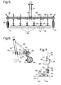
Figure 5 shows a front view in the direction of arrow A offigure 4 ; -
Figure 6 shows a side view in the direction of arrow B offigure 4 ; and -
Figure 7 shows a side view of a component of the foam dispensing machine offigure 4 . - Referring to
figure 1 , there is shown aweed treating apparatus 10 and a tractor 5 (represented schematically). Theweed treating apparatus 10 comprises afoam generating apparatus 12, which is intended to be mounted at the rear of the tractor 5, and afoam dispensing machine 14 which is intended to be mounted at the front of the tractor 5. It will be appreciated that theapparatus 10 might instead be mounted on a different agricultural vehicle, which may be a vehicle dedicated to this use. Thefoam dispensing machine 14 is envisaged as being mounted at the front of such a vehicle, as this enables the driver to align it accurately to kill weeds between rows of crops, but it will be appreciated that the two components of theweed treating apparatus 10 might instead both be mounted on a trailer to be towed behind such an agricultural vehicle. - The tractor 5 includes an engine 6, a cab 7, a three-point linkage 8 at the front, and a power takeoff 9 at the rear. Such features are conventional. The tractor 5 may also provide the facility for raising and lowering the three-point linkage 8.
- Referring now to
figure 2 , thefoam dispensing machine 14 and thefoam generating apparatus 12 are shown separately, without the tractor 5. Thefoam generating apparatus 12 includes asteel frame 20 with abracket 21 on the front side so it can be mounted onto the rear of the tractor 5. Within the lower part of thesteel frame 20 is mounted agenerator 24, which is adapted to be linked by a telescopic drive shaft with an overrun clutch to the power take off 9 from the tractor 5, so that thegenerator 24 is driven by the tractor's engine 6. In this embodiment thegenerator 24 is a three-phase 415 V generator, generating about 80 kVA. Supported by thesteel frame 20 above thegenerator 24 is awater storage tank 26, which may for example have a capacity of 400 or 600 litres. Thesteel frame 20 also carries fourboxes - Referring also to
figure 3 , the box 28 (which is shown partly broken away) encloses threeelectrical heaters 34 each provided with thermal insulation. Thebox 30 on the left side (as shown) of thegenerator 24 encloses control electronics 32 (shown schematically in broken lines), while thebox 31 on the right side (as shown) of thegenerator 24 encloses a pump 36 (shown schematically in broken lines) and solenoid valves 38 (represented schematically). Thebox 29 above theheater box 28 may also contain electronic components. Eachelectrical heater 34 includes an electrical heating element and a cast aluminium block. - In operation of the
foam generating apparatus 12 the water which is to be heated is pumped by thepump 36 from thewater tank 26 through the threeelectrical heaters 34 in series. Eachheater 34 may have a nominal power of 24 kW, and each may be powered by a different phase of the output from thegenerator 24. Eachheater 34 is controlled by thecontrol electronics 32 in accordance with the flow rate of the water, so that the water temperature is raised in stages, typically by between 20°C and 30°C at each stage, to a final temperature between 95°C and 105°C or up to 110°C, which may be above 102°C, for example 107°C. Thecontrol electronics 32 monitors the water temperature at each stage, and also the temperature of theheater 34, for example using thermocouples. - The hot water emerging from the
heater box 28 is at an elevated pressure for example 120 kPa (18 psi) to 135 kPa (20 psi) (absolute pressures), but more typically a higher pressure such as 400 kPa, 500 kPa, or up to 1000 kPa or 1200 kPa because of the pressure created by thepump 36. The hot water does not boil, because of the elevated pressure, until it emerges from a nozzle. By way of example the water flow rate may be up to 10 litres/minute, in this example, which can supply several foam-dispensing nozzles; but if not all the foam-dispensing nozzles are in use, the flow rate of water to theelectrical heaters 34 in theheater box 28 is reduced. This may utilise an electronically-controlled valve to divert some of the water from thepump 36 back to thewater tank 26. - Although the
heater box 28 may be referred to as a reservoir of hot water, it contains only the water required for immediate use, as the water is heated only as it is being dispensed. That is to say, the water is heated on demand. - A surfactant such as an alkyl polyglycoside may be mixed with the liquid in the
water tank 26, or it may be mixed with the water as it is passed into theheater box 28, or may be mixed with the hot water as it flows out of theheater box 28, or after it has emerged from theheater box 28. The quantity of surfactant may be about 0.1% by weight of water, typically between 0.05% and 0.5%, although it may be higher, for example 1%, 1.5% or 2%. - The
solenoid valves 38 control the outflow of hot fluid through various outlet nozzles. For example hot fluid may be supplied to a hand-held spray lance with a nozzle at its end, so an operator walking alongside the tractor 5 can treat individual weeds; or hot fluid may be supplied to spray nozzles mounted behind the rear wheels of the tractor 5, so as to treat weeds growing in the wheel ruts. As the hot fluid emerges from the nozzle it forms a foam which contains steam, which blankets the surface of the weed, and kills the weed. Thefoam dispensing machine 14, described in more detail below, can carry several such dispensing nozzles and enables a large area to be treated easily. - Referring now to
figure 4 , thefoam dispensing machine 14 consists of asupport bar 40 supported at each end by awheel 42. The rear face of thesupport bar 40 is connected bybrackets 43 and hingedparallel plate linkages 44 to acrossbar 46. Thecrossbar 46 carriesbrackets 48 and an upwardly-extendinglink bar 41, which enable it to be connected to the three-point linkage 8 at the front of the tractor 5. - The front face of the
crossbar 46 carries twoheader boxes 50 on thermally insulatingmounts 49, each with aninlet 51 which is connected by a hose 52 (only one is represented, schematically) to one of thesolenoid valves 38;such hoses 52 may extend along the underside of the tractor 5. Eachheader box 50, in this example, has fouroutlet ports 54 to which outlet hoses 55 (only one is represented, schematically) can be connected using dry break hydraulic connectors. Eachheader box 50 also has anoutlet 53 which is connected by a hose equivalent to thehose 52 to carry any excess liquid back to thewater tank 26. Eachhose 52 that extends along the underside of the tractor 5 is provided with a dry break hydraulic connector. - Referring also to
figure 5 , along the front face of thesupport bar 40 is fixed anylon runner 58, and asupport tube 60 is fixed a short distance in front of thenylon runner 58, supported by abracket 59 at the middle of thesupport bar 40 and byend plates 62 which are bolted onto the ends of thesupport bar 40.Several nozzle modules 64 can be mounted along thissupport tube 60, six being shown infigures 2 to 5 . - In
figure 7 onesuch nozzle module 64 is shown in isolation. Themodule 64 includes an L-shapedclamping block 65 shaped to rest against thenylon runner 58 and against the underside of thesupport bar 40. This defines atransverse hole 66 through which thesupport tube 60 passes, and aclamp 67 to secure theblock 65 to thesupport tube 60. It also defines vertical hole through which asupport bar 68 can slide, and aclamp 69 to secure thesupport bar 68 to theblock 65. The lower end of thesupport bar 68 is linked by ahinge 70 to a curved L-shapedbracket 72 to which anozzle support plate 73 is connected. Thenozzle support plate 73 supports threenozzles 74 spaced apart along a straight line, and arranged to spray the hot liquid below thenozzle support plate 73; in plan view, as shown infigure 4 , thenozzle support plate 73 is lozenge-shaped, with rounded ends, but of length about five times its width. Below thenozzle support plate 73 is a flexible rubber curtain orskirt 75 which splays out. Considering the dimensions at the base of the curtain orskirt 75, the length may be 350 mm and the breadth 100 mm; it is desirable to have a ratio of length to breadth of at least 2.5 and preferably at least three, considering the region over which foam is being sprayed at any one time. - The curtain or
skirt 75 may consist of a plurality of flexible rubber curtain portions each of which, along its top edge, can slide along one of two grooves adjacent to the periphery of thenozzle support plate 73, each being of length less than that of the periphery. By adjusting the positions of these curtain portions, and the extent to which they overlap each other, a gap in theskirt 75 may be provided at the rear side of thenozzle support plate 73. Consequently when the hot liquid from thefoam generating apparatus 12 is dispensed through thenozzles 74, foam is generated below thenozzle support plate 73 in a space that is enclosed on the front and the sides, but is not enclosed at the rear. Eachnozzle 74 generates a conical spray of foam (indicated as 74a infigure 7 ). - In addition the L-shaped
bracket 72 also carries aliquid supply manifold 76, with aninlet 78 to communicate with ahose 55 from the header box 50 (seefigure 4 ), and with three outlets 80 (only two of which are visible infigure 7 ) which are connected by hoses 82 (one of which is shown schematically) to thenozzles 74. - The orientation of the
nozzle support plate 73 relative to the L-shapedbracket 72, and so relative to the direction of movement of thefoam dispensing machine 14, can be adjusted, and can be fixed by aclamp 84. - As shown in
figure 6 , thewheels 42 are fixed to the ends of thesupport bar 40 by aclamp 86 which is clamped around thesupport bar 40 and by aninclined shaft 87 to ensure that thewheel 42 rides up over any ruts in the ground. Theinclined shaft 87 includes a jack mechanism with ahandle 88 so the position of thewheel 42 relative to thesupport bar 40 can be adjusted. - The
nozzle modules 64 are hence supported by thesupport tube 60. By temporarily disconnecting oneend plate 62 and removing thewheel support clamp 86 somenozzle modules 64 may be removed, oradditional nozzle modules 64 installed. Theheader boxes 50 provide a total of eightoutlet ports 54, so there can be up to eightnozzle modules 64 mounted on thesupport tube 60. The transverse position of eachnozzle module 64 can be adjusted by sliding it along thesupport tube 60, and then fixed with theclamp 67. The vertical height of thenozzle support plate 73 can be adjusted by raising or lowering thesupport bar 68, and fixed with theclamp 69. Thehinge 70 ensures that thenozzle support plate 73 can swing back to clear any obstacle in its path, such as a stone. - With the
nozzle support plates 73 in the orientation as shown, there are narrow gaps between the regions of the ground that are covered with foam. If thenozzle support plates 73 are adjusted so as to be aligned more closely with the direction of movement, then the gaps between the regions that are covered with foam become larger. On the other hand, if thenozzle support plates 73 are adjusted to extend at a larger angle to the direction of movement, they can be arranged so there are no gaps between the regions treated with foam. Hence thefoam dispensing machine 14 can be adjusted either to treat weeds that are growing between rows of plants, or to treat an entire area. - Considering the effect of a
single nozzle module 64, by adjusting the orientation of thenozzle support plate 73 the width of the ground that is treated may be varied between a minimum of about 100 mm (with the threenozzles 74 aligned with the direction of movement), up to a maximum of about 350 mm (with the threenozzles 74 aligned transverse to the direction of movement). - Typically operation of the
weed treating apparatus 10 is controlled by the operator using a control panel in the cab 7. In operation thepump 36 supplies a stream of water from thewater tank 26 to theelectrical heaters 34 in theheater box 28, this water containing surfactant. Thepump 36 controls both the pressure and the flow rate of the fluid stream. The flow rate is set in accordance with the number ofnozzles 74 that are in use; the operator may for example actuate switches or touch-screen buttons within thecontrol electronics 32 to indicate the number ofoperating nozzles 74. The resulting high pressure liquid stream is supplied through thesolenoid valves 38 and thehoses 52 to theinlets 51 on theheader boxes 50, and so through thehoses 55 to thenozzle modules 64. Any excess liquid in theheader boxes 50 is recirculated back to thewater tank 26. - As a desirable option the cab 7 may include a computer linked to or including a GPS aerial, and linked to the
control electronics 32. Hence the computer can store data that indicates which areas have been treated, and when they were treated. - As a desirable option the
foam dispensing machine 14 may include a pneumatic damper and controlram 90 which extends between the upwardly-extendinglink bar 41 and thesupport bar 40. The pneumatic damper and controlram 90 is shown schematically infigure 6 . This has two effects. When thefoam dispensing machine 14 is being moved over bumpy ground, theram 90 dampens the bouncing movement of thesupport bar 40 and the components fixed to it. If the driver of the tractor 5 raises the three-point linkage 8 with thefoam dispensing machine 14 attached, theram 90 limits the extent to which thesupport bar 40 can drop, restricting the movement of theparallel plate linkages 44, and so enabling the driver to lift thefoam dispensing machine 14 clear of the ground, for example at the end of a row of crops. - The
foam dispensing machine 14 may also be provided with adjustable legs or ajockey wheel 92, as indicated in broken lines infigure 6 , so that thecrossbar 46 does not rest on the ground when disconnected from the tractor 5. - It will be appreciated that a weed killing apparatus may differ from that described in relation to the figures. For example the
weed killing apparatus 10 may be installed permanently as part of a dedicated vehicle, rather than being mounted on a general-purpose vehicle such as the tractor 5. The width of thefoam dispensing machine 14 may differ from that described, and it may carry a smaller number or a larger number ofnozzle modules 64. Where there are a larger number ofnozzle modules 64 it may be appropriate to use awater tank 26 of greater capacity, to prolong the period for which theapparatus 10 can operate without refilling. - The
control electronics 32 preferably includes indicators, visible by the operator, indicating the values of parameters such as temperatures, flow rates, and pressures. In one embodiment a touch-screen controller is provided in a portable box connected via a flexible cable or umbilical cord to thecontrol electronics 32. Such a touch-screen controller may include controls such as an on/off switch for the screen itself, an indicator to show if the power takeoff 9 is at the correct speed, and an emergency stop button to disconnect the power to theheaters 34 and thepump 36. This touch-screen controller would normally be mounted in the cab 7, for example on a sucker pad, so the operator can use it when in the cab 7. Alternatively the operator can remove the touch-screen controller and attach it elsewhere, or hold it in his hand, for example when the operator is controlling weeds using a hand-held spray lance, so he can continue to control foam production without having to climb back into the cab 7.
Claims (12)
- An apparatus (12, 14) suitable for controlling vegetation which apparatus comprises a storage tank (26) for liquid comprising water which may be at ambient temperature; means (36) to supply liquid comprising water from the storage tank (26) to a reservoir (28), where it is to be heated; the reservoir (28) for hot liquid comprising a heating means to heat the liquid in the reservoir (28), the heating means being connectable to a power source (24), and being arranged to heat the liquid to a temperature of above 102°C such that the pressure in the reservoir (28) would be above atmospheric pressure, the heating means comprising a plurality of heaters (34) arranged in series, so the water is heated successively by the heaters (34) and the temperature is raised in a plurality of stages; release means (38) connected to the reservoir (28); and at least one nozzle (74) for applying a stream of foam that contains steam, connected to the reservoir (28) through the release means (38), arranged such that the water is at an elevated pressure, and does not boil until it emerges from a nozzle (74), and such that the liquid combines with air as it leaves the nozzle (74) to form the foam that contains steam; each nozzle (74) being connected to the release means (38) via a header box (50), the header box (50) being provided with an outflow means (53) to carry excess liquid back to the storage tank (26); the apparatus being mounted on a wheeled trolley (40, 42) or a trailer to be propelled by a vehicle (5) or being mounted on a vehicle.
- An apparatus as claimed in claim 1, for use in conjunction with a vehicle (5), the apparatus being such that during use of the apparatus to control vegetation the vehicle (5) provides power (9) to the heating means (34).
- An apparatus as claimed in claim 2, the apparatus comprising a generator (24) which is driven by the vehicle (5), and which provides power to the heating means (34).
- An apparatus as claimed in claim 2 wherein liquid in the hot-liquid reservoir is heated by a burner system which is powered by a fuel carried by the vehicle (5).
- An apparatus as claimed in any one of the preceding claims also comprising means for introducing surfactant into liquid in or from the hot-liquid reservoir, before it reaches the nozzle (74).
- An apparatus as claimed in any one of the preceding claims also comprising a pump (36) to cause liquid to flow through the reservoir (28) as it is heated, the pump (36) controlling the pressure of the liquid in the reservoir (28).
- An apparatus as claimed in any one of the preceding claims also comprising a shroud (75) for the nozzle (74), such that the nozzle (74) is mounted within or inside a shroud (75) or is enclosed on at least one side by a shroud (75).
- An apparatus as claimed in claim 7 wherein each shroud (75) can be arranged to enclose respective nozzle or nozzles (74) at the front and sides, leaving an opening at the rear, relative to the direction of movement.
- An apparatus as claimed in any one of the preceding claims comprising support means for each nozzle (74), wherein each nozzle (74) is supported by a support bar (68) that includes a hinge (70), so that if the nozzle (74) collides with an obstruction as the apparatus is moved over the ground, the nozzle (74) can swing back to clear the obstruction.
- An apparatus as claimed in any one of the preceding claims comprising several nozzles (74) arranged in groups, each group being supported by a respective nozzle support plate (73), the orientation of the nozzle support plate (73) and so of the group of nozzles (74) being adjustable relative to the direction of movement.
- An apparatus as claimed in claim 10 wherein the ratio of width to breadth of the region treated by a group of nozzles (74) is greater than 3.
- A method of controlling vegetation, the method using an apparatus (12, 14) which comprises a storage tank (26) for liquid comprising water which may be at ambient temperature; means (36) to supply liquid comprising water from the storage tank (26) to a reservoir (28), where it is to be heated; the reservoir (28) for hot liquid comprising a heating means to heat liquid comprising water in the reservoir, the heating means being connectable to a power source (24), the heating means comprising a plurality of heaters (34) arranged in series, so the water is heated successively by the heaters (34) and the temperature is raised in a plurality of stages; release means (38) connected to the reservoir (28); at least one nozzle (74) for applying a stream of foam that contains steam, connected to the reservoir (28) through the release means (38); each nozzle (74) being connected to the release means (38) via a header box (50), the header box (50) being provided with an outflow means (53) to carry excess liquid back to the storage tank (26); the apparatus being mounted on a wheeled trolley (40, 42) or a trailer to be propelled by a vehicle (5) or being mounted on a vehicle (5); wherein the method comprises operating the heating means (34) to heat the liquid to a temperature of at least 102°C, and introducing a surfactant into the liquid, with the pressure in the reservoir (28) being above atmospheric pressure, so the liquid does not boil until it emerges from the nozzle (74), and as it emerges from the nozzle (74) the liquid forms a foam which contains steam; wherein the foam comprises up to 10% steam by weight.
Priority Applications (1)
| Application Number | Priority Date | Filing Date | Title |
|---|---|---|---|
| PL11785059T PL2637498T3 (en) | 2010-11-09 | 2011-11-08 | Device for weed control |
Applications Claiming Priority (3)
| Application Number | Priority Date | Filing Date | Title |
|---|---|---|---|
| GBGB1018912.4A GB201018912D0 (en) | 2010-11-09 | 2010-11-09 | Weed control |
| GBGB1112956.6A GB201112956D0 (en) | 2011-07-28 | 2011-07-28 | Weed control |
| PCT/GB2011/052174 WO2012063060A1 (en) | 2010-11-09 | 2011-11-08 | Device for weed control |
Publications (2)
| Publication Number | Publication Date |
|---|---|
| EP2637498A1 EP2637498A1 (en) | 2013-09-18 |
| EP2637498B1 true EP2637498B1 (en) | 2015-04-29 |
Family
ID=44999799
Family Applications (1)
| Application Number | Title | Priority Date | Filing Date |
|---|---|---|---|
| EP11785059.4A Active EP2637498B1 (en) | 2010-11-09 | 2011-11-08 | Device for weed control |
Country Status (19)
| Country | Link |
|---|---|
| US (1) | US9504242B2 (en) |
| EP (1) | EP2637498B1 (en) |
| JP (1) | JP5923103B2 (en) |
| CN (1) | CN103354716B (en) |
| AU (1) | AU2011327878B2 (en) |
| BR (1) | BR112013011464A8 (en) |
| CA (1) | CA2818800A1 (en) |
| CR (1) | CR20130240A (en) |
| DK (1) | DK2637498T3 (en) |
| ES (1) | ES2542633T3 (en) |
| GB (1) | GB2485460B (en) |
| HU (1) | HUE025095T2 (en) |
| IL (1) | IL226251A (en) |
| MX (1) | MX2013005162A (en) |
| NZ (1) | NZ611257A (en) |
| PL (1) | PL2637498T3 (en) |
| PT (1) | PT2637498E (en) |
| WO (1) | WO2012063060A1 (en) |
| ZA (1) | ZA201303763B (en) |
Cited By (1)
| Publication number | Priority date | Publication date | Assignee | Title |
|---|---|---|---|---|
| FR3158414A1 (en) * | 2024-01-19 | 2025-07-25 | Eqo | Weed control system by spraying a heated solution |
Families Citing this family (18)
| Publication number | Priority date | Publication date | Assignee | Title |
|---|---|---|---|---|
| NZ611283A (en) * | 2010-11-09 | 2014-12-24 | Weeding Technologies Ltd | Weed control |
| ITMO20120143A1 (en) * | 2012-05-29 | 2013-11-30 | M M S R L | APPARATUS AND METHOD TO DISERBAL. |
| WO2015027353A1 (en) * | 2013-09-02 | 2015-03-05 | Cisternas Rojas Alex | Vaporising equipment for weed control |
| SE538542C2 (en) * | 2013-09-03 | 2016-09-13 | Ncc Roads Holding Ab | Weed control system |
| GB201413214D0 (en) | 2014-07-25 | 2014-09-10 | Weeding Technologies Ltd | Weed Control |
| USD788550S1 (en) * | 2015-02-17 | 2017-06-06 | 7Rdd Limited | Housing for steam emitting weed killer |
| CN106988199A (en) | 2016-01-20 | 2017-07-28 | 固瑞克明尼苏达有限公司 | Mounting Fixtures for Marker Applicators |
| TR201601103A2 (en) * | 2016-01-27 | 2016-06-21 | Duran Guelec | FLAGING UNIT IN AN AGRICULTURAL MACHINE |
| GB201620238D0 (en) * | 2016-11-29 | 2017-01-11 | Weeding Tech Ltd | Weed Control |
| NL2017899B1 (en) * | 2016-11-30 | 2018-06-11 | Waterkracht Bv | Apparatus and method for controlling weeds |
| US11560680B2 (en) | 2017-07-06 | 2023-01-24 | Bayer Aktiengesellschaft | Apparatus for weed control |
| US10653128B2 (en) * | 2017-08-23 | 2020-05-19 | Cnh Industrial America Llc | Spray system for a self-propelled agricultural machine having adjustable tread width and rear wheel nozzles |
| CA2991231A1 (en) * | 2018-01-08 | 2019-07-08 | X-Steam-Inator Agriculture Products Ltd. | Device and method for delivering steam onto and beneath a field surface |
| EP3823445B1 (en) * | 2018-07-19 | 2024-06-12 | Bayer Aktiengesellschaft | Control of unwanted plants by means of electrical power |
| RU2731577C1 (en) * | 2019-11-19 | 2020-09-04 | Федеральное государственное бюджетное образовательное учреждение высшего образования "Рязанский государственный агротехнологический университет имени П.А. Костычева" | Unit for aerosol treatment of cultivated crops |
| WO2021112785A1 (en) * | 2019-12-05 | 2021-06-10 | Iğdir Üni̇versi̇tesi̇ | Warehouse system in which hot water obtained from solar panels is used for weed control |
| NL2027627B1 (en) * | 2021-02-23 | 2022-09-20 | Fortitude Holdings As | Apparatus and method for controlling weed growing on a ground surface |
| DE102021130936A1 (en) | 2021-11-25 | 2023-05-25 | Michael Sappl | Weed control device, weed control system and vehicle |
Citations (1)
| Publication number | Priority date | Publication date | Assignee | Title |
|---|---|---|---|---|
| US6382523B1 (en) * | 1997-10-23 | 2002-05-07 | Albert Hedegard | Road brine spreader |
Family Cites Families (64)
| Publication number | Priority date | Publication date | Assignee | Title |
|---|---|---|---|---|
| US3001720A (en) * | 1958-08-11 | 1961-09-26 | City Tank Corp | Header construction for spraying equipment |
| GB1163900A (en) * | 1965-12-29 | 1969-09-10 | Urquhart S 1926 Ltd | Improvements relating to Flame Cultivation |
| US3481545A (en) * | 1967-12-26 | 1969-12-02 | Soil Fertility Ltd | Method and apparatus for indicating the extent of land subjected to an agricultural operation |
| US4030244A (en) * | 1976-05-14 | 1977-06-21 | The United States Of America As Represented By The Secretary Of Agriculture | Metering and spray apparatus for horticultural applications |
| JPS5458215A (en) * | 1977-10-18 | 1979-05-10 | Matsushita Electric Ind Co Ltd | Portable sprayer |
| US4340174A (en) * | 1980-06-02 | 1982-07-20 | James Regan | Water heating apparatus, water and heating system and improved boiler |
| US4529104A (en) * | 1983-01-10 | 1985-07-16 | Lor-Al Corporation | Apparatus and method for heating and using air in pneumatic conveyor implement |
| AU561014B2 (en) * | 1983-02-25 | 1987-04-30 | Riyate Pty Limited | Hay pre-conditioner |
| US4763836A (en) * | 1983-09-30 | 1988-08-16 | Lyle William M | Irrigation system for precise water and chemical application |
| FR2555469B1 (en) | 1983-11-25 | 1987-01-16 | Berthoud Sa | IMPROVEMENTS ON AGRICULTURAL SPRAYING FACILITIES |
| DE3401734C2 (en) * | 1984-01-19 | 1987-03-26 | Gebrüder Holder GmbH & Co, 7430 Metzingen | Spraying or spraying device |
| FR2621626B1 (en) * | 1987-10-09 | 1992-02-07 | Gerard Montanier | WASHING DEVICE EQUIPPED WITH A MOTOR VEHICLE, AND COMPRISING A ROTARY WASHING ARM WHICH DELIVERS JETS OF PRESSURIZED HOT WATER TO CLEAN VARIOUS SURFACES |
| US5054688A (en) * | 1989-12-20 | 1991-10-08 | Robwen, Inc. | Foam producing nozzle |
| US5085371A (en) * | 1990-06-15 | 1992-02-04 | Shop-Vac Corporation | Foam creating nozzle system |
| JPH0463535A (en) * | 1990-06-29 | 1992-02-28 | Motoaki Kanbara | Extermination of vermin with steam and apparatus therefor |
| IT220802Z2 (en) | 1990-07-09 | 1993-11-08 | Corona Monica | DEVICE FOR DOSING AND MIXING OF A DETERGENT WITH WATER BY COMPRESSED AIR WITH CONTROLS AVAILABLE ON A SPRAY LANCE THAT ALSO ALLOWS THE TRANSFORMATION OF THE FOAM JET |
| US5297730A (en) * | 1990-09-14 | 1994-03-29 | Aquaheat Technology, Inc. | Apparatus and method for controlling weeds and undergrowth |
| US5366154A (en) * | 1990-09-14 | 1994-11-22 | Aquaheat Technology, Inc. | Apparatus and method for controlling vegetation using high pressure liquid spray |
| JPH04131154A (en) * | 1990-09-25 | 1992-05-01 | Nissho:Kk | Foaming and ejecting device for chemical substance solution |
| NZ237524A (en) | 1991-03-21 | 1995-04-27 | Alistair Renfrew Jerrett | Portable steam producing apparatus for killing weeds and other pests |
| FR2678181B1 (en) | 1991-06-28 | 1995-02-10 | Guy Pommier | SPRAY RAMP. |
| JPH06253715A (en) * | 1991-09-03 | 1994-09-13 | Takatoshi Miyazaki | Herbicidal and insecticidal method and apparatus therefor |
| SE500519C2 (en) * | 1992-02-11 | 1994-07-11 | Sven Linderoth | Pressure regulator for controlling the spray pressure to a number of nozzles in relation to the pump capacity |
| US5385106A (en) * | 1992-08-24 | 1995-01-31 | Langshaw; Eric | Hot water/steam weed killing system |
| US5485962A (en) * | 1992-12-04 | 1996-01-23 | Moss Sales & Service | Pneumatic applicator for agricultural particulates |
| GB2273430A (en) | 1992-12-17 | 1994-06-22 | Weston Terence E | Foam distributor. |
| ES2156870T3 (en) * | 1993-05-07 | 2001-08-01 | Waipuna Internat Ltd | METHOD AND APPLIANCE TO CONTROL VEGETATION. |
| JPH06335344A (en) * | 1993-05-29 | 1994-12-06 | Takatoshi Miyazaki | Herbicidal, germicidal and insecticidal apparatus |
| US5419487A (en) * | 1993-09-29 | 1995-05-30 | Union Carbide Chemicals & Plastics Technology Corporation | Methods for the spray application of water-borne coatings with compressed fluids |
| JPH07163285A (en) * | 1993-12-15 | 1995-06-27 | Wakaba Hara | Method for removing weed and weeder for carrying out the same method |
| US5622123A (en) | 1995-08-10 | 1997-04-22 | Aqua Heat Technology, Inc. | Process and apparatus for killing soil pathogens |
| US5575111A (en) * | 1995-09-28 | 1996-11-19 | Rajamannan; A. H. J. | Method of using hot air foam to kill vegetation and pests |
| US6047900A (en) * | 1995-11-07 | 2000-04-11 | Waipuna International Limited | Vegetation control method and apparatus |
| US5867935A (en) * | 1996-05-03 | 1999-02-09 | Brown; Claude E. | Superheated steam delivering apparatus and agricultural methods therewith |
| US5848492A (en) * | 1996-05-03 | 1998-12-15 | Brown; Claude E. | Agricultural methods with superheated steam |
| US5826522A (en) * | 1996-08-26 | 1998-10-27 | Ag Systems, Inc. | System for applying anhydrous ammonia |
| US6073859A (en) * | 1997-01-28 | 2000-06-13 | Werner Gorgens Consulting And Trading | Process and device for eliminating weeds and cleaning surfaces |
| US5964179A (en) * | 1997-11-15 | 1999-10-12 | Holloway, Jr.; Thomas E. | Method for indicating the extent of land subjected to an agricultural operation |
| DK173327B1 (en) | 1997-12-09 | 2000-07-24 | Fiskars Danmark As | Portable weed control |
| GB9800003D0 (en) | 1998-01-05 | 1998-03-04 | Walters Ian R | Agricultural methods |
| US5927607A (en) * | 1998-02-26 | 1999-07-27 | Hunter Industries Incorporated | Sprinkle with velocity control disc |
| US5947141A (en) * | 1998-03-24 | 1999-09-07 | Nuss; Galen L | Foam inductor system and method of using same |
| US6029589A (en) | 1998-12-07 | 2000-02-29 | Simpson; Stephen | Portable steam weed killing apparatus |
| CA2359860C (en) * | 1999-02-09 | 2007-01-02 | Gregory G. Prull | Method and apparatus for thermally killing weeds |
| US6119963A (en) * | 1999-07-30 | 2000-09-19 | Case Corporation | Full boom pivot breakaway |
| US6345772B1 (en) * | 1999-07-30 | 2002-02-12 | Case Corporation | Field marking system |
| WO2002007513A1 (en) | 2000-07-17 | 2002-01-31 | Waipuna International Limited | Application of heat to control vegetation |
| DE10106895A1 (en) * | 2001-02-10 | 2002-05-08 | Werner Kurfes | Application of hot liquids through porous materials for weed control and crop improvement, combines fluid supply system with exhaust-fed weed after-heater |
| JP2002331261A (en) * | 2001-05-10 | 2002-11-19 | Kioritz Corp | Liquid spraying device |
| PT1450603E (en) * | 2001-09-27 | 2009-10-15 | Waipuna Systems Ltd Malta | Method for weed control with hot foam |
| US20050116071A1 (en) | 2003-11-28 | 2005-06-02 | Rajamannan A. H.J. | Method of using hot air foam to kill vegetation |
| US6969010B1 (en) * | 2004-01-26 | 2005-11-29 | Kriegshauser Duane D | Landscape and agricultural sprayer foam marking attachment |
| US7299950B2 (en) | 2004-09-03 | 2007-11-27 | Rieke Corporation | Dispensing apparatus |
| US7156321B2 (en) * | 2004-09-23 | 2007-01-02 | Lechler Gmbh | Active compound supply system and spraying device for spraying liquids |
| US20070227418A1 (en) * | 2006-03-30 | 2007-10-04 | Polfer Jeffrey J | Apparatus for eliminating undesirable vegetation |
| DE102007036870B4 (en) * | 2007-08-06 | 2010-04-08 | Leeb Mechanik Gmbh | Adjustable nozzle angle |
| JP2009055847A (en) * | 2007-08-31 | 2009-03-19 | Iseki & Co Ltd | Self-propelled control machine |
| CN201150884Y (en) * | 2008-02-03 | 2008-11-19 | 武汉黄鹤拖拉机制造有限公司 | Pesticide spraying device suitable for small-size tillage machinery |
| JP5434071B2 (en) * | 2008-12-25 | 2014-03-05 | 井関農機株式会社 | Self-propelled weeder |
| CN101856641A (en) * | 2009-04-13 | 2010-10-13 | 陈广丰 | Energy accumulation type sprayer and spraying frame |
| CN201414357Y (en) * | 2009-06-08 | 2010-03-03 | 梅州市风华喷雾喷灌机械设备有限公司 | Remote-controlled broad-width air-blast sprayer |
| JP5246668B2 (en) | 2009-07-10 | 2013-07-24 | シンジェンタ ジャパン株式会社 | Herbicide applicator |
| NZ611283A (en) * | 2010-11-09 | 2014-12-24 | Weeding Technologies Ltd | Weed control |
| US8622653B2 (en) * | 2011-05-10 | 2014-01-07 | Arnold Lipes | Apparatus and method for sterilizing seed beds in soil |
-
2011
- 2011-11-08 NZ NZ611257A patent/NZ611257A/en not_active IP Right Cessation
- 2011-11-08 HU HUE11785059A patent/HUE025095T2/en unknown
- 2011-11-08 DK DK11785059.4T patent/DK2637498T3/en active
- 2011-11-08 AU AU2011327878A patent/AU2011327878B2/en not_active Ceased
- 2011-11-08 EP EP11785059.4A patent/EP2637498B1/en active Active
- 2011-11-08 PL PL11785059T patent/PL2637498T3/en unknown
- 2011-11-08 PT PT117850594T patent/PT2637498E/en unknown
- 2011-11-08 CN CN201180064471.3A patent/CN103354716B/en not_active Expired - Fee Related
- 2011-11-08 GB GB1119250.7A patent/GB2485460B/en not_active Expired - Fee Related
- 2011-11-08 JP JP2013538272A patent/JP5923103B2/en not_active Expired - Fee Related
- 2011-11-08 MX MX2013005162A patent/MX2013005162A/en active IP Right Grant
- 2011-11-08 CA CA2818800A patent/CA2818800A1/en not_active Abandoned
- 2011-11-08 US US13/884,159 patent/US9504242B2/en not_active Expired - Fee Related
- 2011-11-08 BR BR112013011464A patent/BR112013011464A8/en active Search and Examination
- 2011-11-08 ES ES11785059.4T patent/ES2542633T3/en active Active
- 2011-11-08 WO PCT/GB2011/052174 patent/WO2012063060A1/en not_active Ceased
-
2013
- 2013-05-09 IL IL226251A patent/IL226251A/en active IP Right Grant
- 2013-05-22 CR CR20130240A patent/CR20130240A/en unknown
- 2013-05-23 ZA ZA2013/03763A patent/ZA201303763B/en unknown
Patent Citations (1)
| Publication number | Priority date | Publication date | Assignee | Title |
|---|---|---|---|---|
| US6382523B1 (en) * | 1997-10-23 | 2002-05-07 | Albert Hedegard | Road brine spreader |
Cited By (1)
| Publication number | Priority date | Publication date | Assignee | Title |
|---|---|---|---|---|
| FR3158414A1 (en) * | 2024-01-19 | 2025-07-25 | Eqo | Weed control system by spraying a heated solution |
Also Published As
| Publication number | Publication date |
|---|---|
| WO2012063060A1 (en) | 2012-05-18 |
| ES2542633T3 (en) | 2015-08-07 |
| JP2014500016A (en) | 2014-01-09 |
| US9504242B2 (en) | 2016-11-29 |
| DK2637498T3 (en) | 2015-07-20 |
| GB201119250D0 (en) | 2011-12-21 |
| CA2818800A1 (en) | 2012-05-18 |
| US20140103138A1 (en) | 2014-04-17 |
| HUE025095T2 (en) | 2016-01-28 |
| ZA201303763B (en) | 2014-08-27 |
| CN103354716B (en) | 2015-09-09 |
| NZ611257A (en) | 2014-12-24 |
| CN103354716A (en) | 2013-10-16 |
| PT2637498E (en) | 2015-08-25 |
| GB2485460B (en) | 2015-01-28 |
| BR112013011464A8 (en) | 2018-07-10 |
| JP5923103B2 (en) | 2016-05-24 |
| MX2013005162A (en) | 2013-10-30 |
| IL226251A0 (en) | 2013-07-31 |
| PL2637498T3 (en) | 2015-10-30 |
| GB2485460A (en) | 2012-05-16 |
| CR20130240A (en) | 2013-09-18 |
| BR112013011464A2 (en) | 2016-08-02 |
| AU2011327878A1 (en) | 2013-06-13 |
| AU2011327878B2 (en) | 2016-01-14 |
| EP2637498A1 (en) | 2013-09-18 |
| IL226251A (en) | 2017-05-29 |
Similar Documents
| Publication | Publication Date | Title |
|---|---|---|
| US9504242B2 (en) | Device for weed control | |
| GB2498088A (en) | Weed control apparatus and nozzle | |
| EP2637497B1 (en) | Device and method for weed control | |
| EP0699028B1 (en) | Vegetation control method and apparatus | |
| CA1289015C (en) | Apparatus and method for subsurface injection of agrochemicals | |
| US20070084422A1 (en) | Portable steam and heat generator for pest control | |
| KR20120075750A (en) | Environment-friendly herbicidal method and system thereof | |
| US20240156078A1 (en) | Device and method for delivering steam onto and beneath a field surface | |
| EP3171694B1 (en) | Weed control | |
| EP3525575B1 (en) | Method and device for soil steam sterilization | |
| JP2014500016A5 (en) | ||
| RU2644196C1 (en) | Selection motoblock-sprayer | |
| KR101140372B1 (en) | Hot Watered-Auto Weed Cutter And Controller | |
| KR102269180B1 (en) | Flame jets | |
| US20210227757A1 (en) | Manually controlled and operable self-propelled seed bed sterilization system and method to prevent weeds | |
| KR101038745B1 (en) | Hot water automatic mower with adjustable spraying position | |
| DK9300377U3 (en) | Hot water spray | |
| CA3162917A1 (en) | Seed bed sterilization system and method to prevent weeds | |
| AU3024100A (en) | Grass field marking apparatus | |
| ITMO20120143A1 (en) | APPARATUS AND METHOD TO DISERBAL. |
Legal Events
| Date | Code | Title | Description |
|---|---|---|---|
| PUAI | Public reference made under article 153(3) epc to a published international application that has entered the european phase |
Free format text: ORIGINAL CODE: 0009012 |
|
| 17P | Request for examination filed |
Effective date: 20130522 |
|
| AK | Designated contracting states |
Kind code of ref document: A1 Designated state(s): AL AT BE BG CH CY CZ DE DK EE ES FI FR GB GR HR HU IE IS IT LI LT LU LV MC MK MT NL NO PL PT RO RS SE SI SK SM TR |
|
| DAX | Request for extension of the european patent (deleted) | ||
| 17Q | First examination report despatched |
Effective date: 20140227 |
|
| GRAP | Despatch of communication of intention to grant a patent |
Free format text: ORIGINAL CODE: EPIDOSNIGR1 |
|
| RAP1 | Party data changed (applicant data changed or rights of an application transferred) |
Owner name: WEEDING TECHNOLOGIES LIMITED |
|
| INTG | Intention to grant announced |
Effective date: 20141113 |
|
| GRAS | Grant fee paid |
Free format text: ORIGINAL CODE: EPIDOSNIGR3 |
|
| GRAA | (expected) grant |
Free format text: ORIGINAL CODE: 0009210 |
|
| AK | Designated contracting states |
Kind code of ref document: B1 Designated state(s): AL AT BE BG CH CY CZ DE DK EE ES FI FR GB GR HR HU IE IS IT LI LT LU LV MC MK MT NL NO PL PT RO RS SE SI SK SM TR |
|
| REG | Reference to a national code |
Ref country code: GB Ref legal event code: FG4D |
|
| REG | Reference to a national code |
Ref country code: CH Ref legal event code: EP |
|
| REG | Reference to a national code |
Ref country code: AT Ref legal event code: REF Ref document number: 723917 Country of ref document: AT Kind code of ref document: T Effective date: 20150515 |
|
| REG | Reference to a national code |
Ref country code: IE Ref legal event code: FG4D |
|
| REG | Reference to a national code |
Ref country code: DE Ref legal event code: R096 Ref document number: 602011016147 Country of ref document: DE Effective date: 20150611 |
|
| REG | Reference to a national code |
Ref country code: CH Ref legal event code: NV Representative=s name: E. BLUM AND CO. AG PATENT- UND MARKENANWAELTE , CH |
|
| REG | Reference to a national code |
Ref country code: DK Ref legal event code: T3 Effective date: 20150716 |
|
| REG | Reference to a national code |
Ref country code: RO Ref legal event code: EPE |
|
| REG | Reference to a national code |
Ref country code: ES Ref legal event code: FG2A Ref document number: 2542633 Country of ref document: ES Kind code of ref document: T3 Effective date: 20150807 |
|
| REG | Reference to a national code |
Ref country code: SE Ref legal event code: TRGR |
|
| REG | Reference to a national code |
Ref country code: NL Ref legal event code: T3 |
|
| REG | Reference to a national code |
Ref country code: PT Ref legal event code: SC4A Free format text: AVAILABILITY OF NATIONAL TRANSLATION Effective date: 20150720 |
|
| REG | Reference to a national code |
Ref country code: LT Ref legal event code: MG4D |
|
| REG | Reference to a national code |
Ref country code: NO Ref legal event code: T2 Effective date: 20150429 |
|
| PG25 | Lapsed in a contracting state [announced via postgrant information from national office to epo] |
Ref country code: LT Free format text: LAPSE BECAUSE OF FAILURE TO SUBMIT A TRANSLATION OF THE DESCRIPTION OR TO PAY THE FEE WITHIN THE PRESCRIBED TIME-LIMIT Effective date: 20150429 Ref country code: HR Free format text: LAPSE BECAUSE OF FAILURE TO SUBMIT A TRANSLATION OF THE DESCRIPTION OR TO PAY THE FEE WITHIN THE PRESCRIBED TIME-LIMIT Effective date: 20150429 Ref country code: FI Free format text: LAPSE BECAUSE OF FAILURE TO SUBMIT A TRANSLATION OF THE DESCRIPTION OR TO PAY THE FEE WITHIN THE PRESCRIBED TIME-LIMIT Effective date: 20150429 |
|
| REG | Reference to a national code |
Ref country code: PL Ref legal event code: T3 |
|
| REG | Reference to a national code |
Ref country code: FR Ref legal event code: PLFP Year of fee payment: 5 |
|
| PG25 | Lapsed in a contracting state [announced via postgrant information from national office to epo] |
Ref country code: GR Free format text: LAPSE BECAUSE OF FAILURE TO SUBMIT A TRANSLATION OF THE DESCRIPTION OR TO PAY THE FEE WITHIN THE PRESCRIBED TIME-LIMIT Effective date: 20150730 Ref country code: RS Free format text: LAPSE BECAUSE OF FAILURE TO SUBMIT A TRANSLATION OF THE DESCRIPTION OR TO PAY THE FEE WITHIN THE PRESCRIBED TIME-LIMIT Effective date: 20150429 Ref country code: LV Free format text: LAPSE BECAUSE OF FAILURE TO SUBMIT A TRANSLATION OF THE DESCRIPTION OR TO PAY THE FEE WITHIN THE PRESCRIBED TIME-LIMIT Effective date: 20150429 Ref country code: IS Free format text: LAPSE BECAUSE OF FAILURE TO SUBMIT A TRANSLATION OF THE DESCRIPTION OR TO PAY THE FEE WITHIN THE PRESCRIBED TIME-LIMIT Effective date: 20150829 |
|
| REG | Reference to a national code |
Ref country code: HU Ref legal event code: AG4A Ref document number: E025095 Country of ref document: HU |
|
| PG25 | Lapsed in a contracting state [announced via postgrant information from national office to epo] |
Ref country code: EE Free format text: LAPSE BECAUSE OF FAILURE TO SUBMIT A TRANSLATION OF THE DESCRIPTION OR TO PAY THE FEE WITHIN THE PRESCRIBED TIME-LIMIT Effective date: 20150429 |
|
| REG | Reference to a national code |
Ref country code: DE Ref legal event code: R097 Ref document number: 602011016147 Country of ref document: DE |
|
| PG25 | Lapsed in a contracting state [announced via postgrant information from national office to epo] |
Ref country code: CZ Free format text: LAPSE BECAUSE OF FAILURE TO SUBMIT A TRANSLATION OF THE DESCRIPTION OR TO PAY THE FEE WITHIN THE PRESCRIBED TIME-LIMIT Effective date: 20150429 Ref country code: SK Free format text: LAPSE BECAUSE OF FAILURE TO SUBMIT A TRANSLATION OF THE DESCRIPTION OR TO PAY THE FEE WITHIN THE PRESCRIBED TIME-LIMIT Effective date: 20150429 |
|
| PLBE | No opposition filed within time limit |
Free format text: ORIGINAL CODE: 0009261 |
|
| STAA | Information on the status of an ep patent application or granted ep patent |
Free format text: STATUS: NO OPPOSITION FILED WITHIN TIME LIMIT |
|
| 26N | No opposition filed |
Effective date: 20160201 |
|
| PG25 | Lapsed in a contracting state [announced via postgrant information from national office to epo] |
Ref country code: SI Free format text: LAPSE BECAUSE OF FAILURE TO SUBMIT A TRANSLATION OF THE DESCRIPTION OR TO PAY THE FEE WITHIN THE PRESCRIBED TIME-LIMIT Effective date: 20150429 |
|
| PG25 | Lapsed in a contracting state [announced via postgrant information from national office to epo] |
Ref country code: MC Free format text: LAPSE BECAUSE OF FAILURE TO SUBMIT A TRANSLATION OF THE DESCRIPTION OR TO PAY THE FEE WITHIN THE PRESCRIBED TIME-LIMIT Effective date: 20150429 |
|
| REG | Reference to a national code |
Ref country code: AT Ref legal event code: UEP Ref document number: 723917 Country of ref document: AT Kind code of ref document: T Effective date: 20150429 |
|
| REG | Reference to a national code |
Ref country code: FR Ref legal event code: PLFP Year of fee payment: 6 |
|
| PG25 | Lapsed in a contracting state [announced via postgrant information from national office to epo] |
Ref country code: BG Free format text: LAPSE BECAUSE OF FAILURE TO SUBMIT A TRANSLATION OF THE DESCRIPTION OR TO PAY THE FEE WITHIN THE PRESCRIBED TIME-LIMIT Effective date: 20150429 Ref country code: SM Free format text: LAPSE BECAUSE OF FAILURE TO SUBMIT A TRANSLATION OF THE DESCRIPTION OR TO PAY THE FEE WITHIN THE PRESCRIBED TIME-LIMIT Effective date: 20150429 |
|
| PG25 | Lapsed in a contracting state [announced via postgrant information from national office to epo] |
Ref country code: CY Free format text: LAPSE BECAUSE OF FAILURE TO SUBMIT A TRANSLATION OF THE DESCRIPTION OR TO PAY THE FEE WITHIN THE PRESCRIBED TIME-LIMIT Effective date: 20150429 |
|
| REG | Reference to a national code |
Ref country code: FR Ref legal event code: PLFP Year of fee payment: 7 |
|
| PGFP | Annual fee paid to national office [announced via postgrant information from national office to epo] |
Ref country code: LU Payment date: 20171120 Year of fee payment: 7 |
|
| PGFP | Annual fee paid to national office [announced via postgrant information from national office to epo] |
Ref country code: NO Payment date: 20171124 Year of fee payment: 7 Ref country code: DK Payment date: 20171122 Year of fee payment: 7 Ref country code: RO Payment date: 20171031 Year of fee payment: 7 Ref country code: HU Payment date: 20171115 Year of fee payment: 7 |
|
| PG25 | Lapsed in a contracting state [announced via postgrant information from national office to epo] |
Ref country code: MK Free format text: LAPSE BECAUSE OF FAILURE TO SUBMIT A TRANSLATION OF THE DESCRIPTION OR TO PAY THE FEE WITHIN THE PRESCRIBED TIME-LIMIT Effective date: 20150429 |
|
| PGFP | Annual fee paid to national office [announced via postgrant information from national office to epo] |
Ref country code: MT Payment date: 20171023 Year of fee payment: 7 |
|
| PG25 | Lapsed in a contracting state [announced via postgrant information from national office to epo] |
Ref country code: AL Free format text: LAPSE BECAUSE OF FAILURE TO SUBMIT A TRANSLATION OF THE DESCRIPTION OR TO PAY THE FEE WITHIN THE PRESCRIBED TIME-LIMIT Effective date: 20150429 |
|
| REG | Reference to a national code |
Ref country code: DK Ref legal event code: EBP Effective date: 20181130 Ref country code: NO Ref legal event code: MMEP |
|
| REG | Reference to a national code |
Ref country code: CH Ref legal event code: PL |
|
| PG25 | Lapsed in a contracting state [announced via postgrant information from national office to epo] |
Ref country code: NO Free format text: LAPSE BECAUSE OF NON-PAYMENT OF DUE FEES Effective date: 20181130 Ref country code: LU Free format text: LAPSE BECAUSE OF NON-PAYMENT OF DUE FEES Effective date: 20181108 |
|
| PG25 | Lapsed in a contracting state [announced via postgrant information from national office to epo] |
Ref country code: RO Free format text: LAPSE BECAUSE OF NON-PAYMENT OF DUE FEES Effective date: 20181108 Ref country code: LI Free format text: LAPSE BECAUSE OF NON-PAYMENT OF DUE FEES Effective date: 20181130 Ref country code: HU Free format text: LAPSE BECAUSE OF NON-PAYMENT OF DUE FEES Effective date: 20181109 Ref country code: CH Free format text: LAPSE BECAUSE OF NON-PAYMENT OF DUE FEES Effective date: 20181130 |
|
| PG25 | Lapsed in a contracting state [announced via postgrant information from national office to epo] |
Ref country code: DK Free format text: LAPSE BECAUSE OF NON-PAYMENT OF DUE FEES Effective date: 20181130 |
|
| REG | Reference to a national code |
Ref country code: DE Ref legal event code: R119 Ref document number: 602011016147 Country of ref document: DE |
|
| PG25 | Lapsed in a contracting state [announced via postgrant information from national office to epo] |
Ref country code: MT Free format text: LAPSE BECAUSE OF NON-PAYMENT OF DUE FEES Effective date: 20181108 |
|
| PG25 | Lapsed in a contracting state [announced via postgrant information from national office to epo] |
Ref country code: DE Free format text: LAPSE BECAUSE OF NON-PAYMENT OF DUE FEES Effective date: 20200603 |
|
| PG25 | Lapsed in a contracting state [announced via postgrant information from national office to epo] |
Ref country code: PL Free format text: LAPSE BECAUSE OF NON-PAYMENT OF DUE FEES Effective date: 20191108 |
|
| PGFP | Annual fee paid to national office [announced via postgrant information from national office to epo] |
Ref country code: SE Payment date: 20221130 Year of fee payment: 12 Ref country code: NL Payment date: 20221129 Year of fee payment: 12 Ref country code: IT Payment date: 20221125 Year of fee payment: 12 Ref country code: IE Payment date: 20221129 Year of fee payment: 12 Ref country code: GB Payment date: 20221124 Year of fee payment: 12 Ref country code: FR Payment date: 20221123 Year of fee payment: 12 Ref country code: AT Payment date: 20221124 Year of fee payment: 12 |
|
| PGFP | Annual fee paid to national office [announced via postgrant information from national office to epo] |
Ref country code: BE Payment date: 20221123 Year of fee payment: 12 |
|
| PGFP | Annual fee paid to national office [announced via postgrant information from national office to epo] |
Ref country code: PT Payment date: 20230505 Year of fee payment: 12 |
|
| REG | Reference to a national code |
Ref country code: SE Ref legal event code: EUG |
|
| REG | Reference to a national code |
Ref country code: NL Ref legal event code: MM Effective date: 20231201 |
|
| REG | Reference to a national code |
Ref country code: AT Ref legal event code: MM01 Ref document number: 723917 Country of ref document: AT Kind code of ref document: T Effective date: 20231108 |
|
| PG25 | Lapsed in a contracting state [announced via postgrant information from national office to epo] |
Ref country code: AT Free format text: LAPSE BECAUSE OF NON-PAYMENT OF DUE FEES Effective date: 20231108 |
|
| GBPC | Gb: european patent ceased through non-payment of renewal fee |
Effective date: 20231108 |
|
| PG25 | Lapsed in a contracting state [announced via postgrant information from national office to epo] |
Ref country code: AT Free format text: LAPSE BECAUSE OF NON-PAYMENT OF DUE FEES Effective date: 20231108 |
|
| PG25 | Lapsed in a contracting state [announced via postgrant information from national office to epo] |
Ref country code: PT Free format text: LAPSE BECAUSE OF NON-PAYMENT OF DUE FEES Effective date: 20240508 |
|
| REG | Reference to a national code |
Ref country code: BE Ref legal event code: MM Effective date: 20231130 |
|
| PG25 | Lapsed in a contracting state [announced via postgrant information from national office to epo] |
Ref country code: SE Free format text: LAPSE BECAUSE OF NON-PAYMENT OF DUE FEES Effective date: 20231109 Ref country code: PT Free format text: LAPSE BECAUSE OF NON-PAYMENT OF DUE FEES Effective date: 20240508 |
|
| PGFP | Annual fee paid to national office [announced via postgrant information from national office to epo] |
Ref country code: TR Payment date: 20240506 Year of fee payment: 13 |
|
| PG25 | Lapsed in a contracting state [announced via postgrant information from national office to epo] |
Ref country code: NL Free format text: LAPSE BECAUSE OF NON-PAYMENT OF DUE FEES Effective date: 20231201 |
|
| REG | Reference to a national code |
Ref country code: IE Ref legal event code: MM4A |
|
| PG25 | Lapsed in a contracting state [announced via postgrant information from national office to epo] |
Ref country code: NL Free format text: LAPSE BECAUSE OF NON-PAYMENT OF DUE FEES Effective date: 20231201 |
|
| PG25 | Lapsed in a contracting state [announced via postgrant information from national office to epo] |
Ref country code: IE Free format text: LAPSE BECAUSE OF NON-PAYMENT OF DUE FEES Effective date: 20231108 |
|
| PG25 | Lapsed in a contracting state [announced via postgrant information from national office to epo] |
Ref country code: GB Free format text: LAPSE BECAUSE OF NON-PAYMENT OF DUE FEES Effective date: 20231108 |
|
| PG25 | Lapsed in a contracting state [announced via postgrant information from national office to epo] |
Ref country code: BE Free format text: LAPSE BECAUSE OF NON-PAYMENT OF DUE FEES Effective date: 20231130 |
|
| PG25 | Lapsed in a contracting state [announced via postgrant information from national office to epo] |
Ref country code: FR Free format text: LAPSE BECAUSE OF NON-PAYMENT OF DUE FEES Effective date: 20231130 |
|
| PGFP | Annual fee paid to national office [announced via postgrant information from national office to epo] |
Ref country code: ES Payment date: 20240828 Year of fee payment: 13 |
|
| PG25 | Lapsed in a contracting state [announced via postgrant information from national office to epo] |
Ref country code: IE Free format text: LAPSE BECAUSE OF NON-PAYMENT OF DUE FEES Effective date: 20231108 Ref country code: GB Free format text: LAPSE BECAUSE OF NON-PAYMENT OF DUE FEES Effective date: 20231108 Ref country code: FR Free format text: LAPSE BECAUSE OF NON-PAYMENT OF DUE FEES Effective date: 20231130 Ref country code: BE Free format text: LAPSE BECAUSE OF NON-PAYMENT OF DUE FEES Effective date: 20231130 |
|
| PG25 | Lapsed in a contracting state [announced via postgrant information from national office to epo] |
Ref country code: IT Free format text: LAPSE BECAUSE OF NON-PAYMENT OF DUE FEES Effective date: 20231108 |
|
| PG25 | Lapsed in a contracting state [announced via postgrant information from national office to epo] |
Ref country code: IT Free format text: LAPSE BECAUSE OF NON-PAYMENT OF DUE FEES Effective date: 20231108 |
|
| REG | Reference to a national code |
Ref country code: ES Ref legal event code: FD2A Effective date: 20251230 |
|
| PG25 | Lapsed in a contracting state [announced via postgrant information from national office to epo] |
Ref country code: ES Free format text: LAPSE BECAUSE OF NON-PAYMENT OF DUE FEES Effective date: 20241109 |